Article

A Novel Adaptive Super-Twisting Sliding Mode Control Scheme with Time-Delay Estimation for a Single Ducted-Fan Unmanned Aerial Vehicle

1
Department of Smart Robot Convergence and Application Engineering, Pukyong National University, Busan 48513, Korea
2
Department of Mechanical System Engineering, Pukyong National University, Busan 48513, Korea
*
Authors to whom correspondence should be addressed.
Actuators 2021, 10(3), 54; https://doi.org/10.3390/act10030054
Submission received: 8 February 2021 / Revised: 2 March 2021 / Accepted: 5 March 2021 / Published: 7 March 2021
(This article belongs to the Section Aerospace Actuators)

Abstract

:
This article proposes a novel adaptive super-twisting sliding mode control scheme with a time-delay estimation technique (ASTSMC-TDE) to control the yaw angle of a single ducted-fan unmanned aerial vehicle system. Such systems are highly nonlinear; hence, the proposed control scheme is a combination of several control schemes; super-twisting sliding mode, TDE technique to estimate the nonlinear factors of the system, and an adaptive sliding mode. The tracking error of the ASTSMC-TDE is guaranteed to be uniformly ultimately bounded using Lyapunov stability theory. Moreover, to enhance the versatility and the practical feasibility of the proposed control scheme, a comparison study between the proposed controller and a proportional-integral-derivative controller (PID) is conducted. The comparison is achieved through two different scenarios: a normal mode and an abnormal mode. Simulation and experimental tests are carried out to provide an in-depth investigation of the performance of the proposed ASTSMC-TDE control system.

1. Introduction

The ducted-fan unmanned aerial vehicle (DUAV) technologies have consistently evolved since their first emergence to fulfill military objectives and humanitarian relief operations [1,2,3,4]. In recent years, DUAV systems have demonstrated successful departures from unprepared sites and small deck spaces [5]. Moreover, these ducted-fan vehicles have been subjected to turbulent environments [6,7] and gusty winds [8,9], and their performance was studied. A DUAV system is mainly required to accurately follow a predefined trajectory [10,11]. Hence, the landing process should as well be considered as one of the most important aspects in developing such systems [12,13].
Generally, the landing operation includes the yaw motion control and the landing process. The yaw motion control herein keeps the DUAV at a proper angle before landing safely. However, air conditions often create uneven aerodynamic forces that affect the DUAV. Which makes it difficult to control the yaw angle because of the high nonlinearities, parametric uncertainties, and unknown disturbances. In particular, the high nonlinearities—undesirable factors, for instance—can lead to the DUAV’s instability. To cope with these issues, several robust control laws have been designed. For instance, sliding mode control (SMC) [14,15], time-delay technique [16,17,18], feedback control [19], process control [20,21], and model predictive control theories [22,23] were applied.
The SMC is a well-established and widely applied control scheme [24,25]. The remarkable thing about the SMC is that it can be extended to a super-twisting SMC (STSMC) to cope with unknown system dynamics [26,27]. The control gains of the STSMC are designed to be greater than the upper bound of the uncertain terms so that robustness can be achieved [28,29]. However, the chattering phenomenon is a serious problem that may result in significant wear of the actuators [30]. Therefore, low-pass filtering methods were suggested as a solution [31].
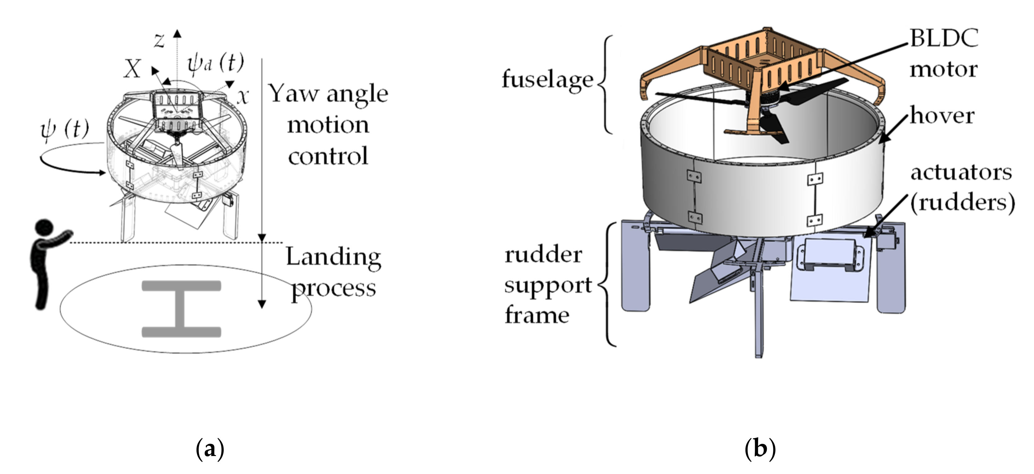
On the other hand, angle motion control plays a significant role in the landing process of the DUAVs. The DUAV systems need to be tracked and kept in the right-angle position before the start of autonomous or manual landing processes, as shown in Figure 1. However, these systems may lose one or two of their steering actuators during their mission, which will reduce the control performances. This is an undesirable situation that requires the control scheme with unchanged control gains to increase the power capacity of the remaining actuators, thus maintaining the desired angle before landing the DUAV, Figure 2a.
Based on these facts, this study proposes a new approach to overcome the high nonlinearity of the DUAV systems. The control method adopted is an adaptive super-twisting sliding mode with time-delay estimation. Besides, a comparison between the ASTSMC-TDE controller and a proportional-integral-derivative (PID) controller was conducted. The performance of the proposed controller is investigated through two different operation modes. A normal mode (NM) when the four actuators operate normally, and an abnormal mode (AM) when one actuator is broken and another has a reduced power capacity.
The contributions of this paper are listed as follows:
  • A novel control scheme (ASTSMC-TDE) is proposed to guarantee better performance and system stability;
  • The introduction of the TDE technique, which is the key to cancel out the disturbances the DUAV system is subjected to—the high nonlinearity [32,33,34], parametric uncertainties [35,36], and unknown disturbances. Nonetheless, the TDE technique results in errors since the estimation is delayed by one sample time [37].
  • An adaptive sliding mode controller (ASMC) is introduced to suppress the TDE errors. However, when the switching gains of the ASMC become somewhat larger, the “parameter drift” phenomenon occurs [38].
  • Hence, a smooth adaptive version of the ASMC with a dead-zone modification technique is introduced to guarantee system robustness.
On another note, the tracking error of ASTSMC-TDE is guaranteed to be uniformly ultimately bounded (UUB) according to Lyapunov stability theory. Moreover, to determine the practical feasibility of the proposed controller, simulations and experimental tests were conducted.
This article is organized as follows. Section 2 presents the description and the modeling of the yaw angle of the DUAV system. In Section 3, the design of the novel adaptive super-twisting sliding mode with time-delay estimation is addressed in detail. Evaluation methods to assess the performance of the proposed controller are described in Section 4. In Section 5, simulations of the DUAV system yaw angle are illustrated. Section 6 presents the experimental results of the proposed control scheme applied to a real DUAV system. Finally, conclusions are drawn in Section 7.

2. Description and Modeling of DUAV System

2.1. Description of the DUAV System

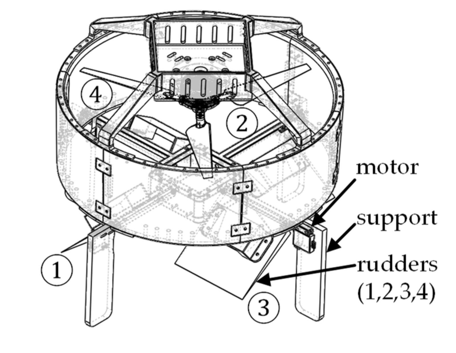
The DUAV system, illustrated in Figure 2b and Figure 3 consists of actuators (rudders), brushless DC motor system (BLDC motor and propellers), hover, and fuselage. The BLDC motor system has two main objectives. First, it generates the necessary thrust force to steer the yaw angle of the DUAV to the right position alongside the rudder system. Second, it counteracts gravitation during the landing. On the other hand, the rudder system is operated by four servomotors that are controlled by PWM signals. A load-cell sensor measures the thrust force of the BLDC motor. The yaw angle of the DUAV is fed back through a gyro sensor. The communication between the computer and the system, as well as with the sensors, is achieved via the RS-232 protocol. The experiment apparatus of the DUAV system is detailed in the experiment section.
In this article, to enhance the force balance and aerodynamics of the DUAV system, the rudders are arranged so that two successive actuators are positioned symmetrically. In the AM mode, for instance, actuator four is inactive and the power capacity of actuator three is reduced. Throughout the whole paper, the following assumptions are made:
Assumption 1
([39]).We assume that the slipstream axis is coincident with the fan axis.
Assumption 2
([39]).We assume that there is no possibility for the slipstream to mix up with other external duct flows.
Assumption 3
([39]).We assume that there is no crosswind during the experimental tests.

2.2. Modeling of the DUAV System

The general mathematical model of the yaw channel of the DUAV system is described as:
I z ψ ¨ t = k A , τ u t , ρ τ t + f τ u t , ρ + f i ψ t + f g ψ ¨ t , τ u t
where ψ t R , ψ ˙ t R and ψ ¨ t R are the yaw angle, the yaw angular velocity, and the yaw angular acceleration, respectively. A is the area of the rudders and ρ is the density of air. τ u t R and τ t R are the control signals of the thrust force and the rudder system, respectively. I z is the moment of inertia in the z-direction. k A , τ u t , ρ R is the identified control gains. f τ u t , ρ R is the spinning torque and f i ψ t R is the initial torque of the rudder system. f g ψ ¨ t , τ u t R represents the gyroscopic torque resulting from the rotation of the DUAV system.
Generally, yaw motion control of the DUAV system is a difficult task due to the high degree of nonlinearity that the system is subjected to. The spinning force, the gyroscopic torque, and undesired factors are examples of these nonlinearities. The parametric uncertainties refer to the uncertainty in the identified moment of inertia in the z-direction and the control gains. Moreover, the mathematical model in Equation (1) is a single-input single-output system, which has low maneuverability during normal mode motion control. To enhance the versatility of motion control in normal and abnormal modes, the mathematical representation of a multiple-input single-output system can be rearranged from Equation (1) as follows:
ψ ¨ * t = K τ t + f τ u t , ρ + f i ψ t + f g ψ ˙ t , τ u t + f u t
where the vector ψ * t = ψ 1 t , ψ 2 t , ψ 3 t , ψ 4 t T R 4 is the yaw angle of the DUAV system, the vector elements represent the rotation angles of the rudders. K R 4 × 4 is a constant gain matrix. τ t = τ 1 t , τ 2 t , τ 3 t , τ 4 t T R 4 is the control signal vector fed to the rudders. f ( ) , f i ( ) , f g ( ) , and f u ( ) are, respectively, the spinning force, the initial force, the force of inertia of the gyro, and the undesired values.
Based on the research in [37], a simple representation of Equation (2) is obtained as:
ψ ¨ * t = K ¯ τ t + Γ t
where Γ t = f τ u t , ρ + f i ψ t + f g ψ ˙ t , τ u t + f u t R 4 includes all the nonlinear terms addressed in Equation (2). K ¯ = d i a g k 1 , k 2 , k 3 , k 4 R 4 × 4 is a constant matrix to be determined using MATLAB identification toolbox. In this paper, we assume that the DUAV dynamics in Equation (3) satisfy K ¯ 2 δ K for δ K > 0 . The yaw angle of the DUAV is devised based on the output angle of the rudders, i.e., ψ * t = c ¯ ψ ψ t ; where c ¯ ψ R 4 is a column vector of weights that results in ψ t = ψ 1 t + ψ 2 t + ψ 3 t + ψ 4 t .

3. Novel Adaptive Super-Twisting Sliding Mode Control with Time-Delay Estimation

3.1. Control System Design

This article aims to control ψ t the yaw angle of the DUAV system to properly track the reference ψ d t . This means that the yaw angle error e t = ψ d t ψ t should approach zero.
Subsequently, the yaw angle error of the actuator is defined as C ψ c ¯ ψ e t , where C ψ = d i a g C ψ 11 , C ψ 22 , C ψ 33 , C ψ 44 R 4 × 4 is a positive weighting matrix. Thus, a sliding manifold variable is chosen as follows:
s t = C ψ c ¯ ψ e ˙ t + K s C ψ c ¯ ψ e t
where s t = s 1 t , s 2 t , s 3 t , s 4 t T R 4 and K s = d i a g 1 K s , 2 K s , 3 K s , 4 K s R 4 × 4 . We note that K s is a positive gain matrix preserving the stability condition. We construct the control law with a super-twisting sliding manifold given by:
τ t = K ¯ 1 Γ ^ t + K ¯ 1 C ψ 1 C ψ c ¯ ψ ψ ¨ d t + k s s t 1 / 2 s i g n s t + h s s i g n s t d t + K s C ψ c ¯ ψ e ˙ t
where k s = k s 1 , k s 2 , k s 3 , k s 4 T R 4 and h s = h 1 , h 2 , h 3 , h 4 T R 4 are positive gain vectors. The operator · is defined as the absolute value of each element of the input vector, where · = · i . The operator is the Hadamard product [40,41]. s i g n · is defined as the corresponding signum function of each element of the input vector, where s i g n · = s i g n · i . Γ ^ ( t ) denotes the estimation obtained from one sampling time-delayed measurement of Γ ( t ) using the TDE technique. This estimation can be expressed as follows:
Γ ^ t = Γ t L = ψ ¨ * t L K ¯ τ t L
where L R is the sampling period. Substituting Equation (6) into Equation (5), we obtain the following:
τ t = K ¯ 1 ψ ¨ * t L + τ t L TDE + K ¯ 1 C ψ 1 C ψ c ¯ ψ ψ ¨ d t + k s s t 1 / 2 s i g n s t + h s s i g n s t d t + K s C ψ c ¯ ψ e ˙ t STSMC
Consider the following Lyapunov function candidate chosen to guarantee the system stability:
V s t = i = 1 n = 4 ξ i T P i ξ i
where ξ i = s i t 1 / 2 s i g n s t h i s i g n s t d t T R 2 and P i is a positive semi-definite symmetric matrix. i = 1 , , 4 R denotes the order of the actuators. Substituting the control law in Equation (7) into Equation (3), and combined with the sliding manifold variable from Equation (4), the time derivative of the Lyapunov function in Equation (8) yields the following:
V ˙ s t = i = 1 n = 4 s i t 1 / 2 ξ i T P i C ψ i i Γ ^ i t Γ i t 0 1 2 s i t 1 / 2 ξ i T Q i ξ i
Proof of Equation (9).
The proof is given in Appendix A. □
Thus, if the term Γ ^ ( t ) Γ ( t ) can be zero or Γ ( t ) can be properly estimated, where Γ t = Γ 1 t , Γ 2 t , Γ 3 t , Γ 4 t T , then the time derivative of the Lyapunov function in Equation (9) is semi-negative V ˙ s 0 . According to Barbalat’s lemma and Equation (4), we can verify that s ( t ) is bounded, i.e., e ( t ) is also bounded. Therefore, the stability of the control law in Equation (7) is guaranteed.
In this study, an STSMC is designed to stabilize the linear system obtained using the TDE technique. The estimation of the nonlinear values in Equation (6) implies that the estimated value Γ ^ ( t ) can be similar to that of Γ ( t ) if the sampling time L is sufficiently small [35]. However, Γ ( t ) cannot be accurately estimated even for a small sampling period due to the limitations of implementation conditions caused by measurement noises, high nonlinearity, uncertain factors, etc.
The error value between Γ ^ ( t ) and Γ ( t ) is inevitable and it is called the TDE error. Thus, the design of a control law to suppress the TDE error is of great interest. To achieve this objective, an additional ASMC term is introduced to the control law in Equation (7). The resulting control law is as follows:
τ t = K ¯ 1 ψ ¨ * t L + τ t L TDE + K ¯ 1 C ψ 1 C ψ c ¯ ψ ψ ¨ d t + k s s t 1 / 2 s i g n s t + h s s i g n s t d t + K s C ψ c ¯ ψ e ˙ t STSMC + K ¯ 1 Φ ^ t ASMC
where Φ ^ t = ϕ ^ 1 t , ϕ ^ 2 t , ϕ ^ 3 t , ϕ ^ 4 t T R 4 is an updating switching vector of TDE errors. Therefore, when the TDE error equals zero, the proposed control law in Equation (10) is equivalent to the one in Equation (7). Moreover, the signum function s i g n s t = s i g n s 1 t , s i g n s 2 t , s i g n s 3 t , s i g n s 4 t T R 4 is defined as follows:
s i g n s i t = 1 , i f s i t > 0 0 , i f s i t = 0 1 , i f s i t < 0
However, instead of the signum function in Equation (11), an approximation is proposed to reduce the chattering in the proposed controller. The approximation of the signum function is given by:
s i g n s t s t s t + ζ
where ζ = ζ 1 , ζ 2 , ζ 3 , ζ 4 T R 4 is a positive gain vector, and the operator is defined as Hadamard division.
Substituting the approximation of the signum function from Equation (12) into Equation (10), the proposed control law can be rearranged as the following:
τ t = K ¯ 1 ψ ¨ * t L + τ t L TDE + K ¯ 1 C ψ 1 C ψ c ¯ ψ ψ ¨ d t + k s s t 1 / 2 s t s t + ζ STSMC + K ¯ 1 C ψ 1 h s s t s t + ζ d t + K s C ψ c ¯ ψ e ˙ t STSMC + K ¯ 1 Φ ^ t ASMC
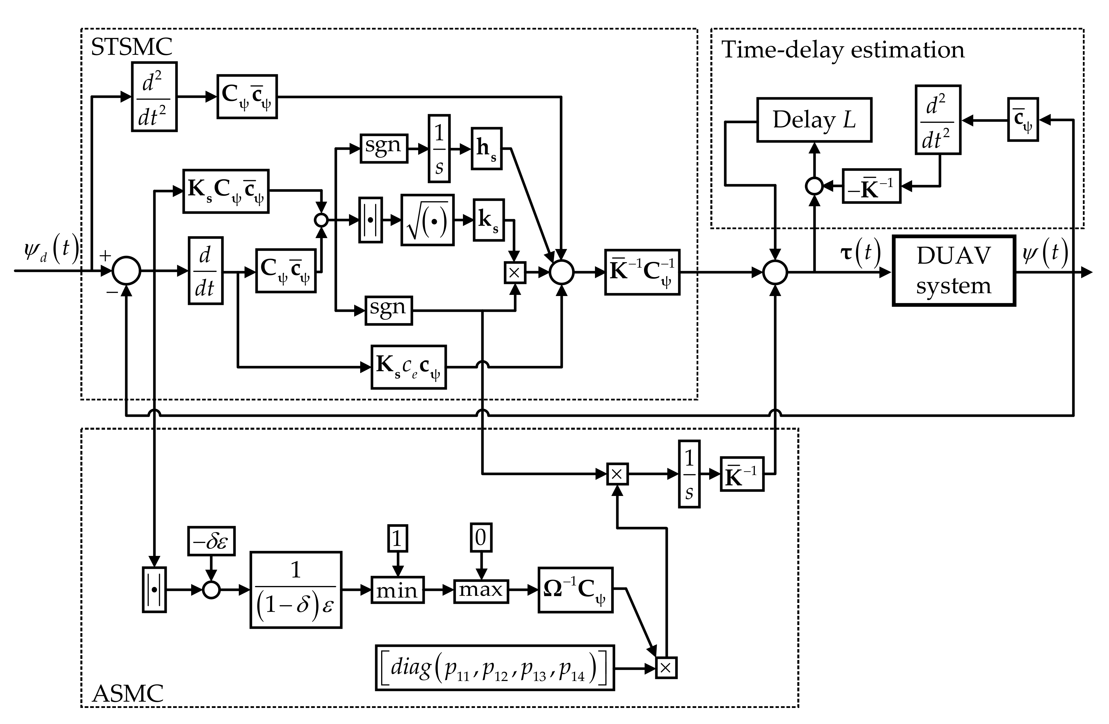
The proposed control law in Equation (13) can be interpreted with a block diagram as shown in Figure 4. The adaptive law of the proposed controller is defined by a positive gain matrix Ω = d i a g Ω 11 , Ω 22 , Ω 33 , Ω 44 R 4 × 4 given as:
ϕ ^ ˙ i t = Ω i i 1 C ψ i i p 1 i s i g n s i t
In practice, the “parameter drift” phenomenon is inevitable and it is caused by unpredicted disturbances—electrical noise, shaking, etc. In this regard, a smooth adaptation law with dead-zone modification was introduced by Slotine and Coetsee in [38]. Accordingly, we define a constant 0 < δ < 1 and an updating error ε > 0 , and let us consider a Lipschitz-continuous modulation function in the following form:
μ e t = max 0 , min 1 , e t δ ε 1 δ ε
By substituting the Lipschitz-continuous modulation function from Equation (15) into Equation (14), the smooth adaptation law with dead-zone modification is derived as:
ϕ ^ ˙ i t = μ e t Ω i i 1 C ψ i i p 1 i s i g n s i t
The drawback of this equation is that when e t > ε then the adaptive law is operated by Equation (16). However, when e t enters the area e t + T < ε as T the adaptive term is frozen, i.e., Φ ^ ˙ t + T = 0 as T .

3.2. Stability Analysis

Lemma 1
([37]).The control gain matrix K ¯ in Equation (3) is required to satisfy the following condition:
I K K ¯ 1 2 < 1
Thus for all t 0 , then ψ ¨ * t L ψ ¨ * t 2 0 as L 0 and the TDE errors are bounded by Γ ˜ , i.e., Γ t Γ ^ t Γ ˜ .
Lemma 2.
The DUAV actuators are controlled using the proposed control scheme in Equations (10) and (14). The adaptation gain Φ ^ t is upper bounded by a positive constant for t 0 , i.e.:
Φ ^ t Φ ˜
Proof of Lemma 2.
The proof is given in Appendix B. □
Given the following positive Lyapunov function candidate defined as:
V t = i = 1 n = 4 ξ i T P i ξ i + 1 2 Γ ˜ i ϕ ^ i t 0 T Ω i i 0 0 Ω i i Γ ˜ i ϕ ^ i t 0
Its time derivative yields:
V ˙ t = i = 1 n = 4 ξ ˙ i T P i ξ i + ξ i T P i ξ ˙ i + Γ ˜ i ϕ ^ i t 0 T Ω i i 0 0 Ω i i ϕ ^ ˙ i t 0
Proof of Equation (18).
The proof is given in Appendix C. □
Substituting Equations (4) and (9) into Equation (18) results in:
V ˙ t = i = 1 n = 4 s i t 1 / 2 ξ i T P i C ψ i i E i 0 1 2 s i t 1 / 2 ξ i T Q i ξ i + Λ i t
where Λ i t and the TDE errors E i t are defined as Γ ˜ i ϕ ^ i t 0 T Ω i i 0 0 Ω i i ϕ ^ ˙ i t 0 and Γ ^ i t Γ i t , respectively.
By substituting Equations (6) and (10) into Equation (19), we obtain the following expression:
V ˙ t = i = 1 n = 4 1 2 s i t 1 / 2 ξ i T Q i ξ i + s i t 1 / 2 ξ i T P i C ψ i i E i C ψ i i ϕ ^ i t 0 + Λ i t
Substituting Lemma 1 into Equation (20) results in:
V ˙ t i = 1 n = 4 1 2 s i t 1 / 2 ξ i T Q i ξ i + s i t 1 / 2 ξ i T P i C ψ i i Γ ˜ i C ψ i i ϕ ^ i t 0 + Λ i t = i = 1 n = 4 1 2 s i t 1 / 2 ξ i T Q i ξ i + Γ ˜ i ϕ ^ i t 0 T s i t 1 / 2 P i ξ i C ψ i i + Ω i i 0 0 Ω i i ϕ ^ ˙ i t 0
Proof of Equation (21).
The proof is given in Appendix D. □
From Equation (14), the term s i t 1 / 2 P i ξ i C ψ i i + Ω i i 0 0 Ω i i ϕ ^ ˙ i t 0 equals zero, hence the derivative of the Lyapunov function in Equation (21) is semi-negative, i.e., V ˙ t 0 . The application of Barbalat’s Lemma and Equation (4) indicates that s i ( t ) is bounded, which implies that e ( t ) is also bounded. Therefore, the global system stability is guaranteed with the control law in Equation (10) or the extended controller in Equation (13).

4. Evaluation Methods

The authors conducted a series of independent evaluation methods as means to verify the performance of the proposed controller in comparison with other control schemes. The first evaluation tool is the root mean square error (RMSE) method, expressed in Equation (22). This method serves as a tool to evaluate the behavior of the yaw angle error e t .
R M S E t = 1 n i = 1 n ψ d t ψ t 2
However, the RMSE method alone is unable to give a comprehensive evaluation of the control algorithms. Therefore, the integral of the time multiplied by the absolute value of the yaw angle error (ITAE), as well as the integral of the square value (ISV) of the actuator’s control input signal τ t is additionally investigated [37]. The ITAE method in Equation (23) is used to measure the tracking error of the entire error curve. The ISV method in Equation (24) shows the energy consumption of the actuators. These performance indices are defined as follows:
I T A E t = 0 t t e t d t
I S V t = 0 t τ 2 t d t

5. Simulation Studies

5.1. Simulation Setup

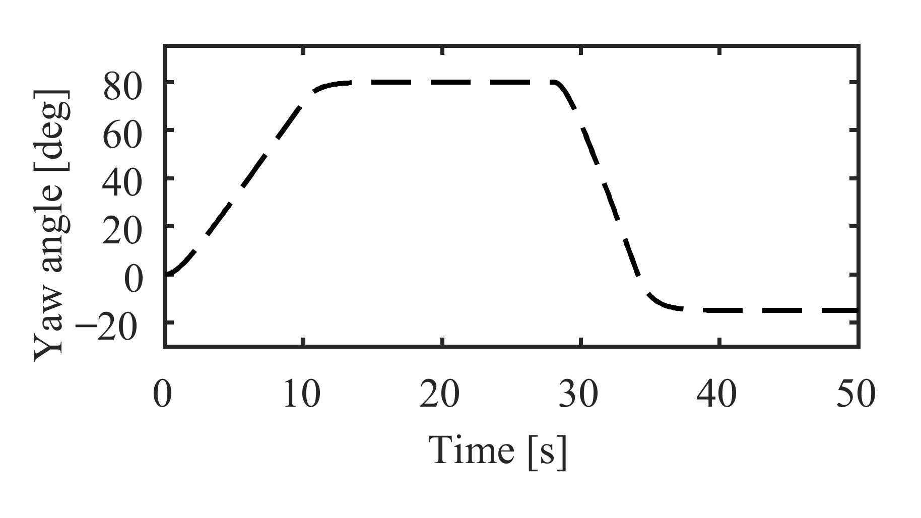
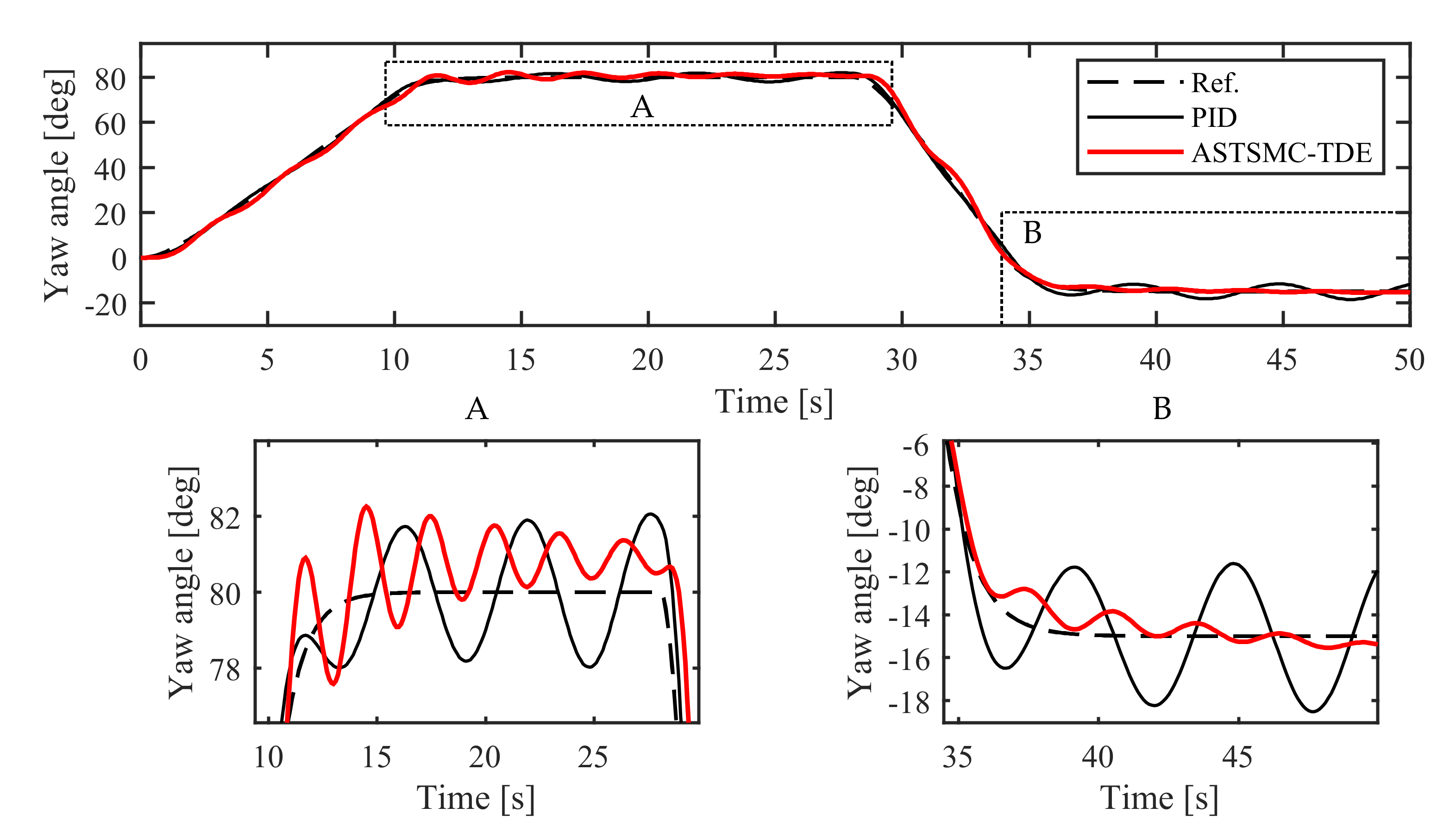
The simulation tests with the proposed control scheme (ASTSMC-TDE) are conducted using the mathematical model described in Equation (3). The desired reference trajectory is shown in Equation (25) and illustrated in Figure 5.
ψ d t = 8 t if   t 10   s 80 if   t 28   s 95 / 6 t + 1570 / 3 if   t 34   s 15 otherwise
The identification and the tuning of the DUAV parameters were conducted using the system identification toolbox integrated with MATLAB. The parameters in Equation (3) are identified such that Lemma 1 is satisfied, thus K ¯ = d i a g 0.501 , 0.501 , 0.501 , 0.501 . The column vector of weights in Equations (4) and (13) is defined as c ¯ ψ = 0.25 , 0.25 , 0.25 , 0.25 T . Besides, the actuators’ weighting matrices are defined as C ψ = d i a g 1 , 1 , 1 , 1 in NM and C ψ = d i a g 1.6 , 1.25 , 0.1 , 1 × 10 7 in AM configuration. In this study, especially, the positive symmetric matrix P i is chosen as a diagonal matrix given by P i = d i a g 10 , 1 , [42]. The initial values of the DUAV at t 0 = 0 are ψ t 0 = 0 , ψ ˙ t 0 = 0 , τ t 0 = 0 , 0 , 0 , 0 T , ψ ¨ * t 0 L = 0 , and τ t 0 L = 0 , 0 , 0 , 0 T . The sampling time is defined as L = 100 m s and the low pass filter is selected as 1 / s + 1 .

5.2. Simulation Results

5.2.1. Simulation in NM Mode

The efficiency of the proposed control scheme (ASTSMC-TDE) is studied through simulation tests in comparison with a PID controller. In all fairness, the control laws adopted use unchanged control gains in both NM and AM modes.
The control gains of the ASTSMC-TDE from Equation (13) are calculated as k s = 3258.843 1 , 1 , 1 , 1 T , ζ = 85000 1 , 1 , 1 , 1 T , h s = 517.965 1 , 1 , 1 , 1 T , and K s = d i a g 0.42024 , 0.42024 , 0.42024 , 0.42024 . The PID control gains are assigned as k p = 1.4865 1 , 1 , 1 , 1 T , k i = 9.9544 1 , 1 , 1 , 1 T , and k d = 7.1175 1 , 1 , 1 , 1 T .
The updating error ε and the constant δ of the adaptive law in Equation (16) are designed to balance between the adaptation speed and the tracking performance. This means that with large control gains the ASMC is adapting faster but has an underdamped response. Thus, the ASMC control gains are designed as Φ ^ t 0 = 0 , 0 , 0 , 0 T , Ω = d i a g 0 . 0025 , 0 . 0025 , 0 . 0025 , 0 . 0025 , ε = 2 , and δ = 0.9 . The simulation results of the NM mode are shown in Figure 6, Figure 7, Figure 8, Figure 9, Figure 10 and Figure 11.
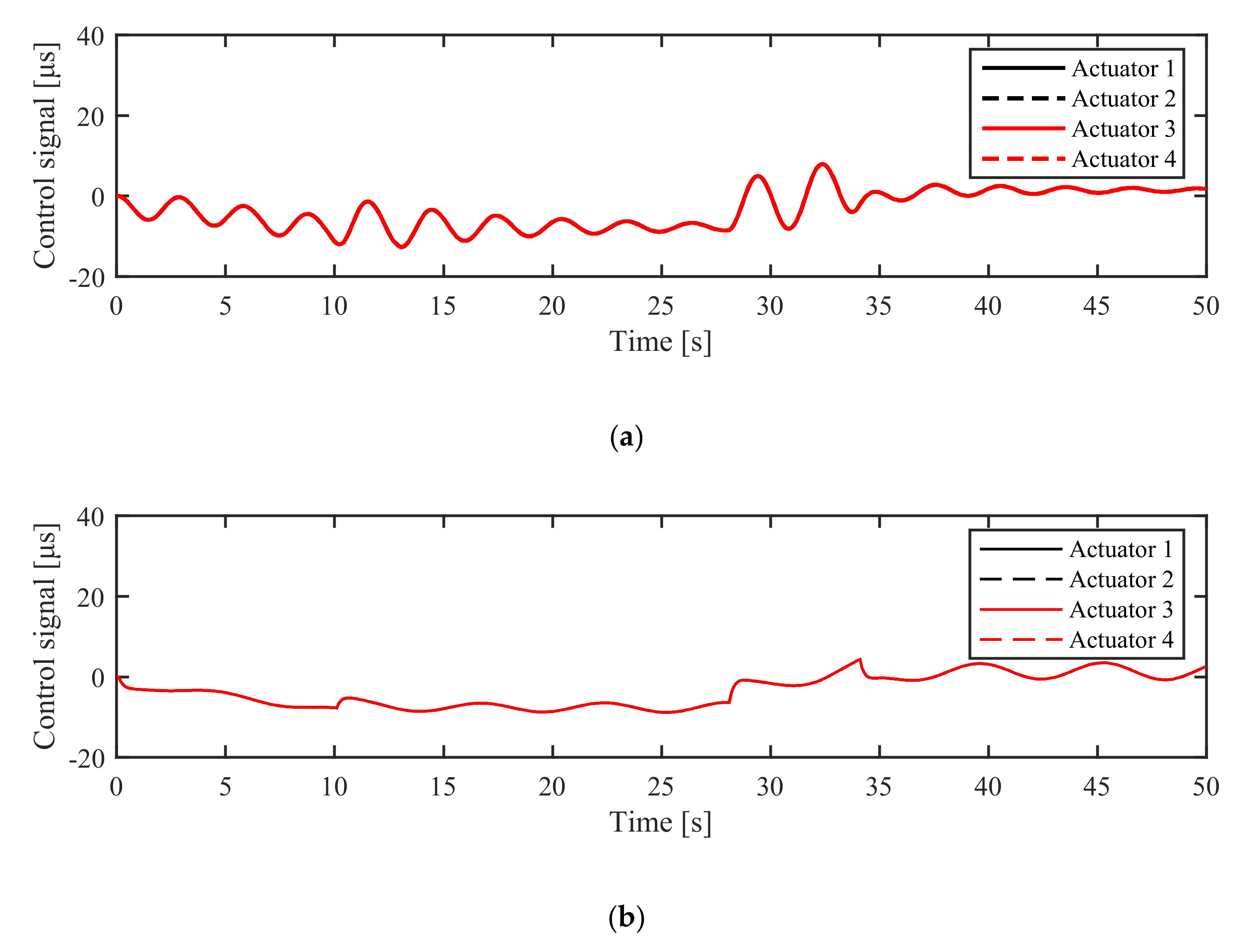
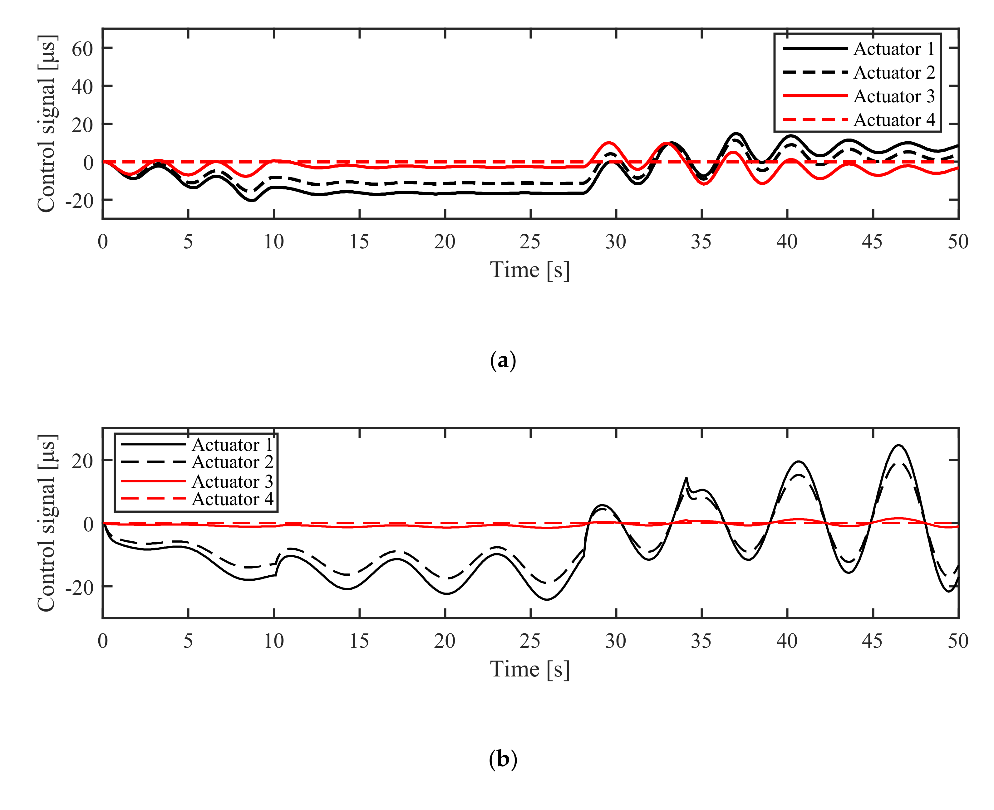
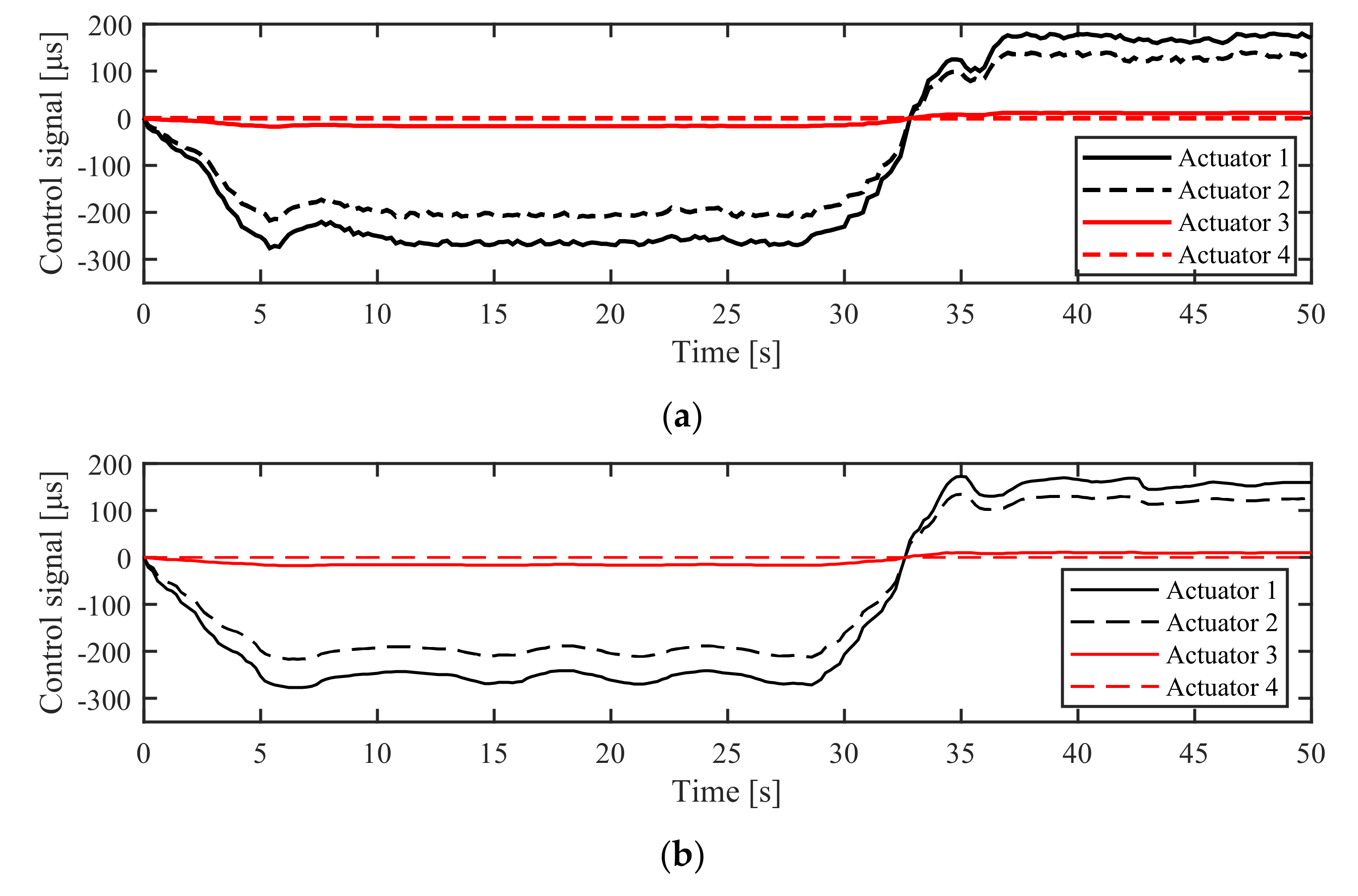
To begin with, Figure 6 shows the detailed yaw angle trajectory tracking performance. The proposed ASTSMC-TDE controller has good tracking, fast adaptation, and fast convergence to the reference signal. The controller adapts quickly with the time-varying reference, which can be seen clearly at the curves where the rate of the desired orientation changes. The tracking errors of the proposed control scheme, as shown in Figure 7, are less than those of the PID controller. The control signals, which represent the amount of time the controllers take to send the PWM signals to the actuators, are illustrated and compared in Figure 8.
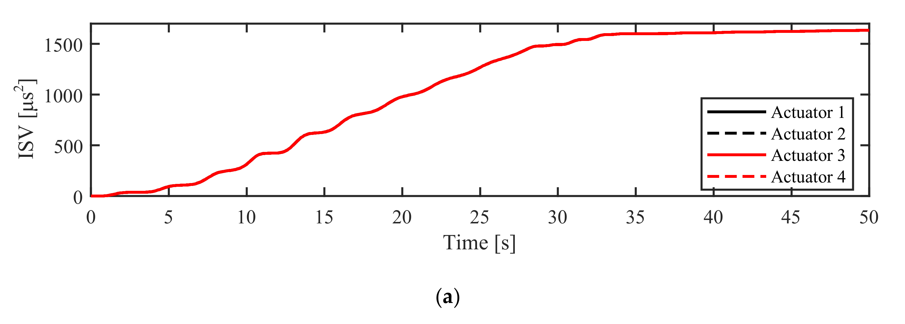
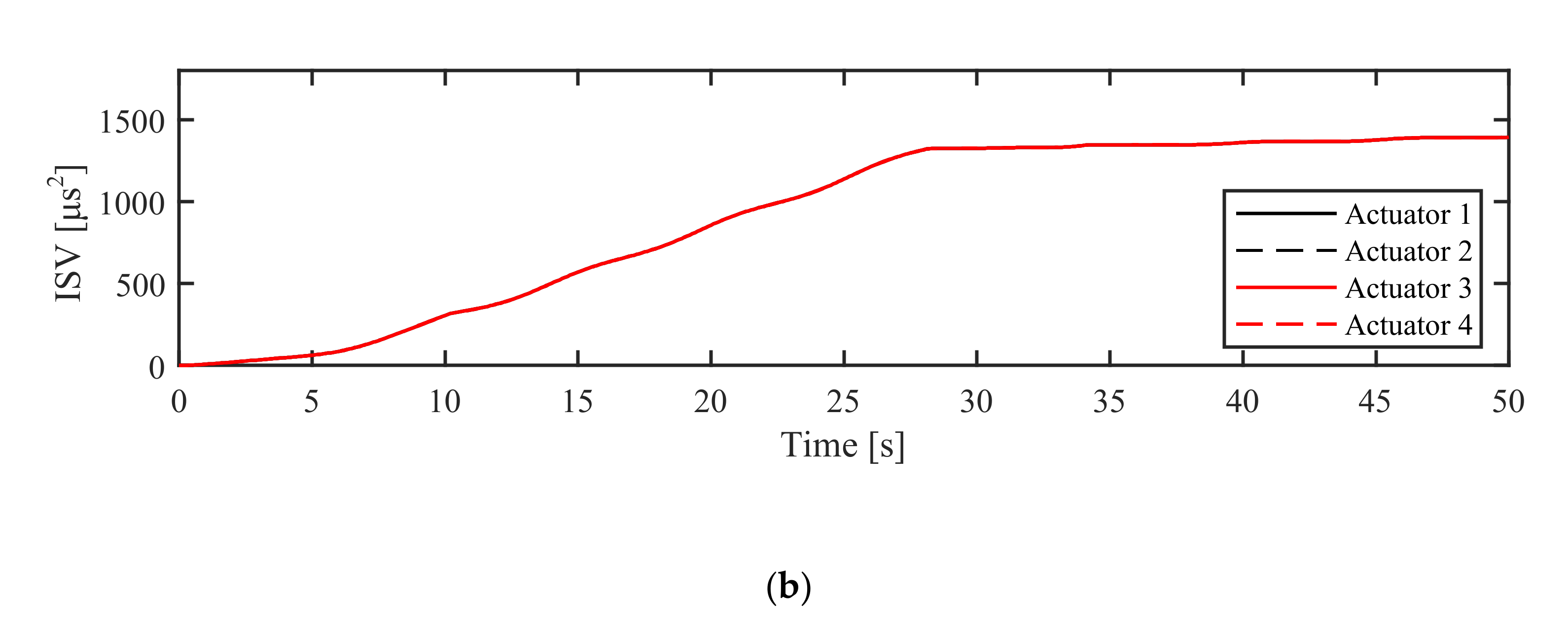
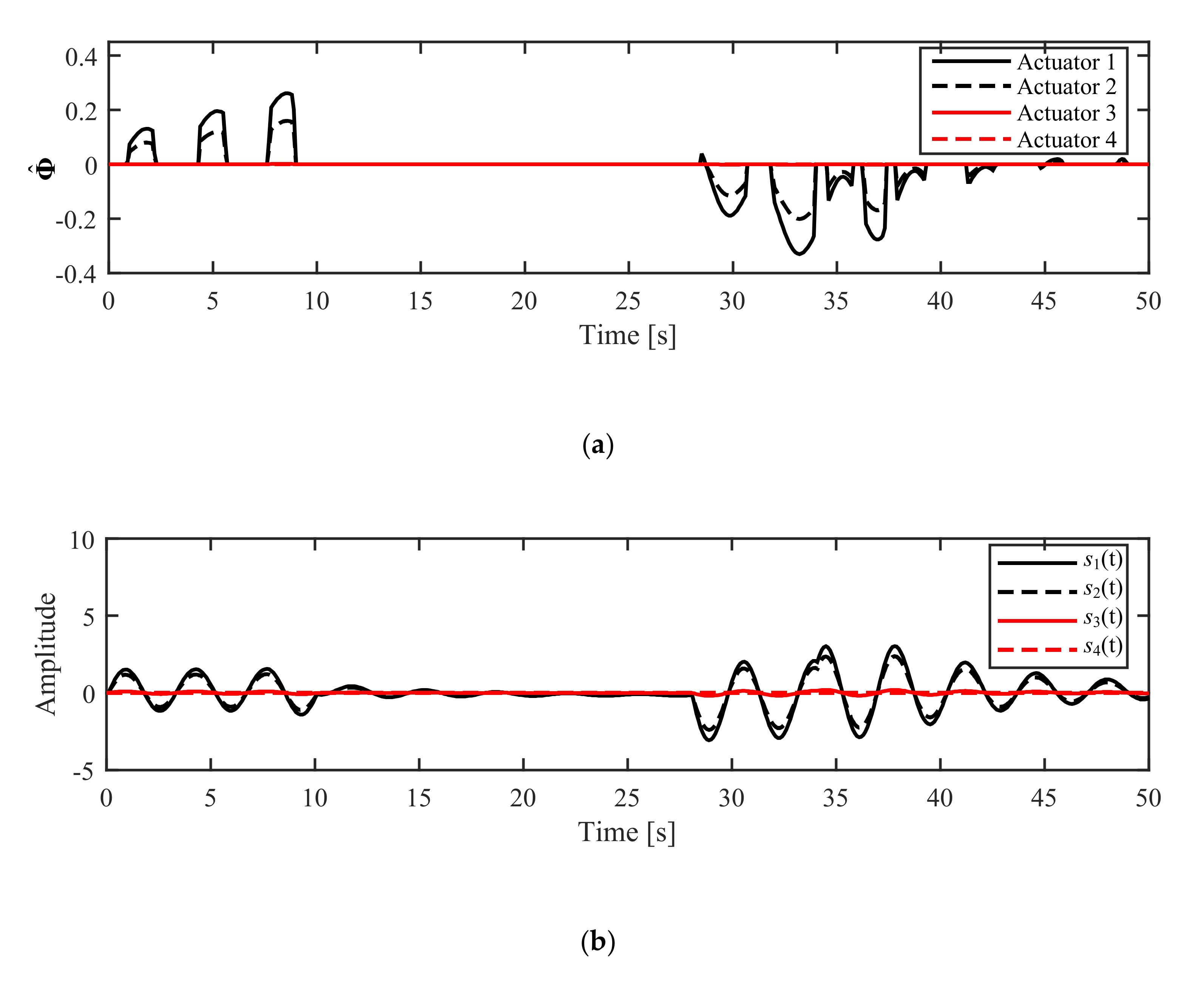
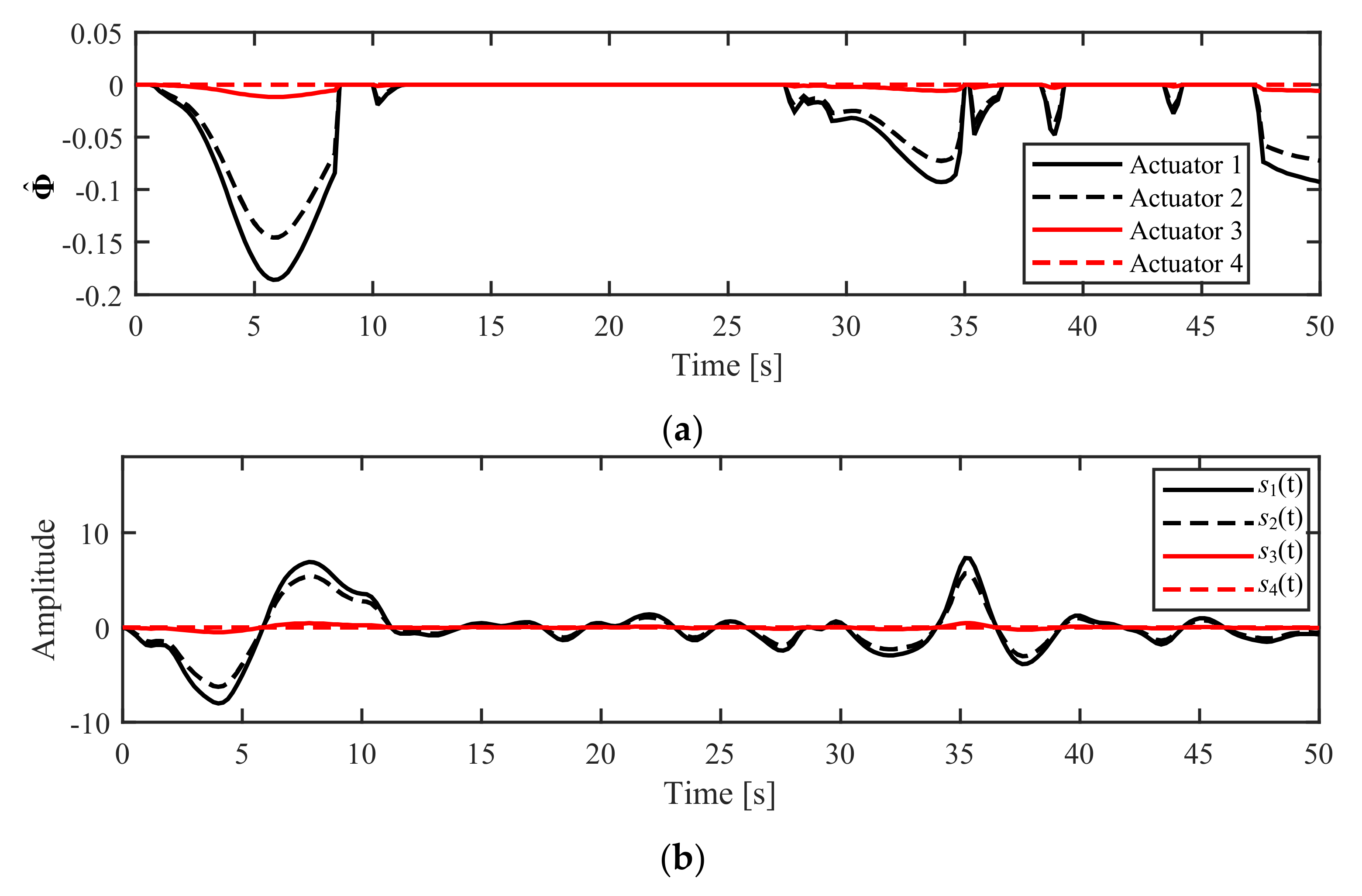
The performance analysis of both control schemes is further conducted using the ISV performance index. Additionally, the boundedness of the adaptive term and the chattering phenomenon of the sliding manifold are two more features of the proposed control law that are investigated and illustrated in Figure 9. Figure 9a shows that the adaptive term does not diverge and it is bounded by an upper bound, as proven mathematically in Lemma 2. While in Figure 9b, the amplitude of the chattering is small and keeps on diminishing.
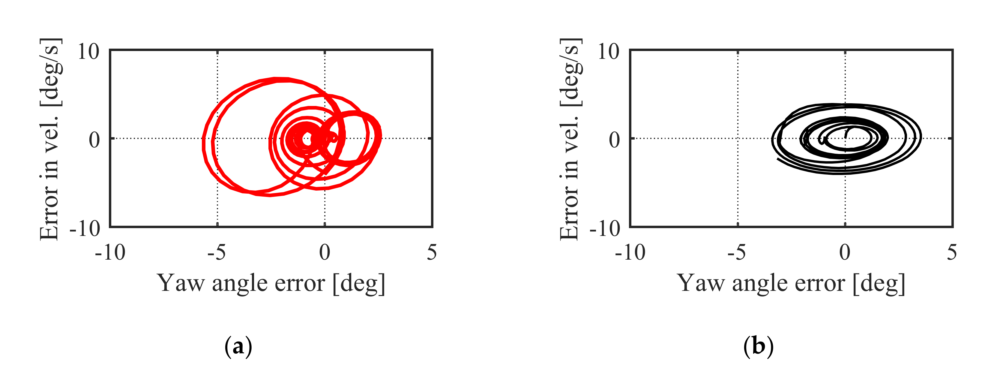
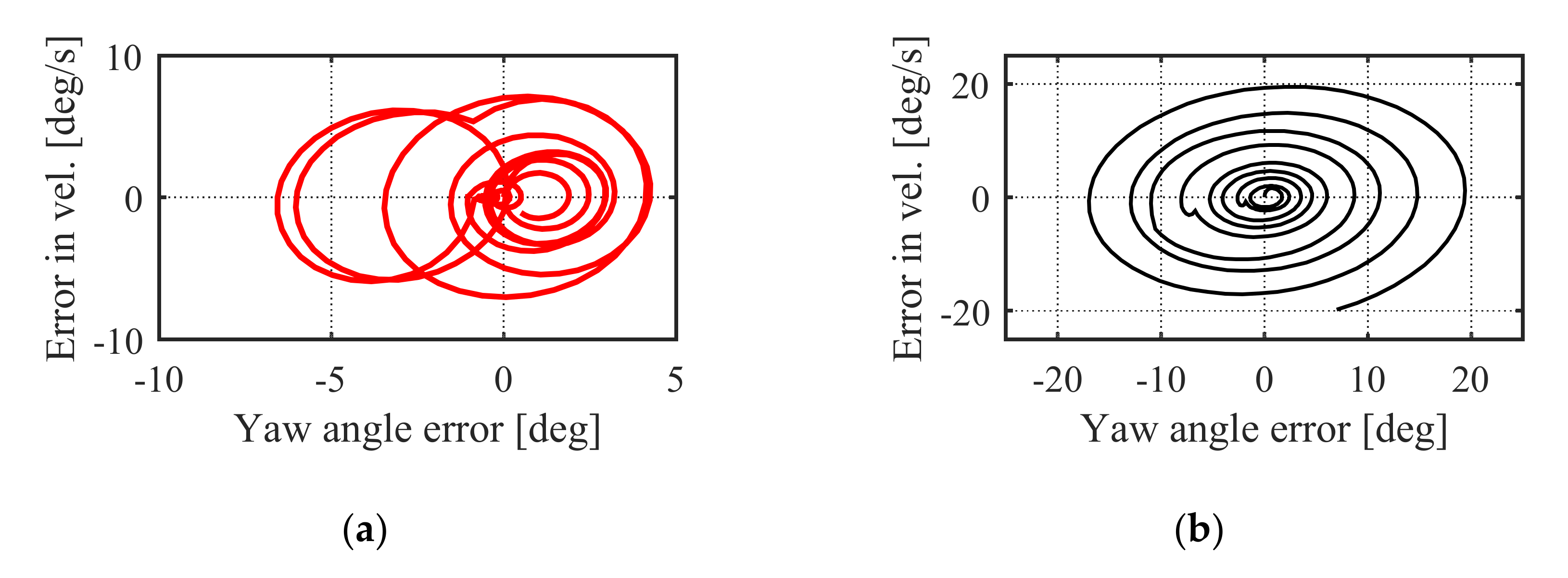
Besides, the performance of both control schemes are evaluated through the phase portrait characteristics, RMSE in Equation (22), ITAE in Equation (23), and ISV in Equation (24). As illustrated in Figure 10, the phase portrait of ASTSMC-TDE has a more stable node and focus compared to the PID control. The phase portrait proves that the ASTSMC-TDE has a fast adaptation and good tracking abilities compared to the PID controller.
Figure 11 shows the ISV values of both controllers throughout the simulation time. For a clearer comparison, the last RMSE, ITAE, and ISV values of both control schemes are summarized in Table 1.

5.2.2. Simulation in AM Mode

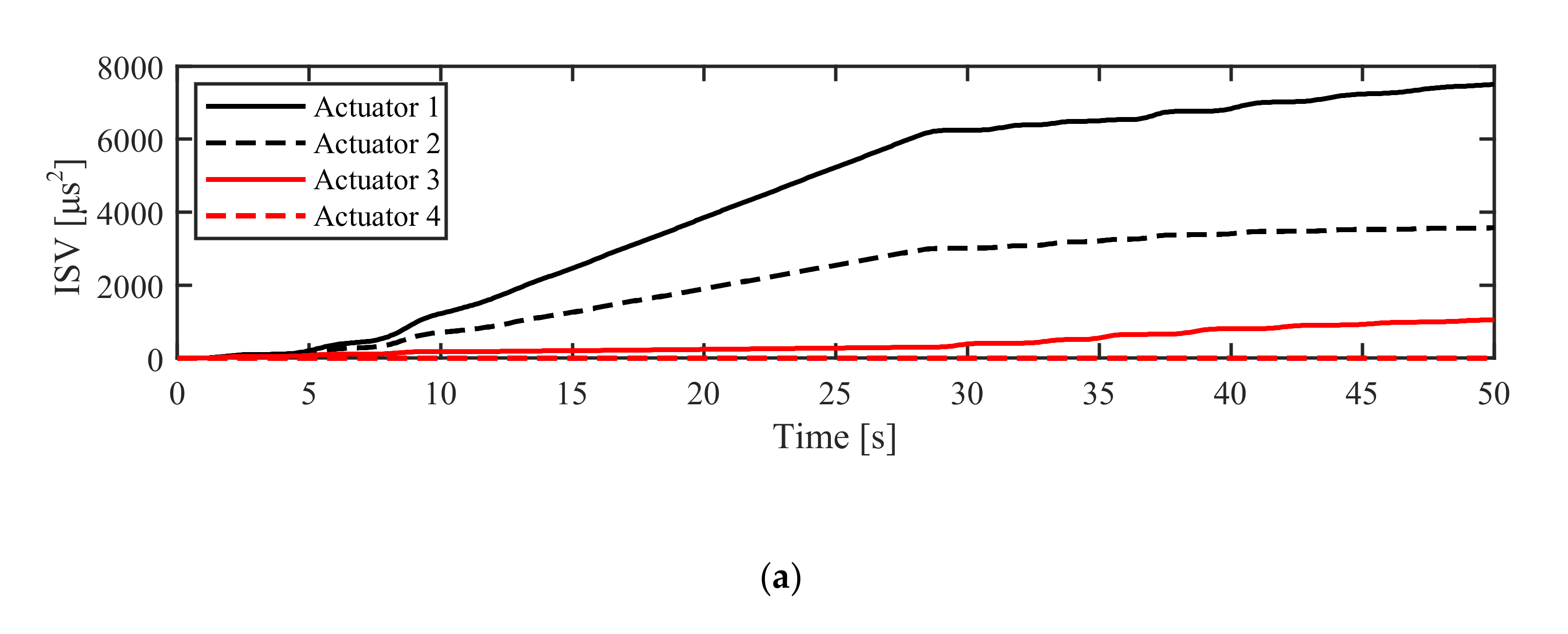
In the AM mode, failure in one or more actuators may occur unpredictably. Hence, a modification in the weighting matrix of actuators is needed such that the influence of the failed actuators can be neglected and the operating actuators would receive higher weights. In this specific simulation of the AM mode, the failure occurs in the 3rd and 4th actuators; the 4th actuator is completely inactive, while the 3rd actuator is provided with 10% of its normal power capacity. The weighting matrix is tuned as previously mentioned, and the system performances in this mode are investigated and illustrated in Figure 12, Figure 13, Figure 14, Figure 15, Figure 16 and Figure 17.
In the AM mode as well, the proposed ASTSMC-TDE controller shows good tracking and fast adaptation to the reference. This means that before landing, the DUAV followed the trajectory with the proper angular position. On the contrary, the PID control becomes unstable, as can be seen in Figure 12, Figure 13 and Figure 14 through the unstoppable amplitude increase of the tracking trajectory and the control signals. The resulting errors of the proposed controller are smaller than those of the PID controller. Moreover, the boundedness of the adaptive term and the amplitude of the chattering are depicted in Figure 15.
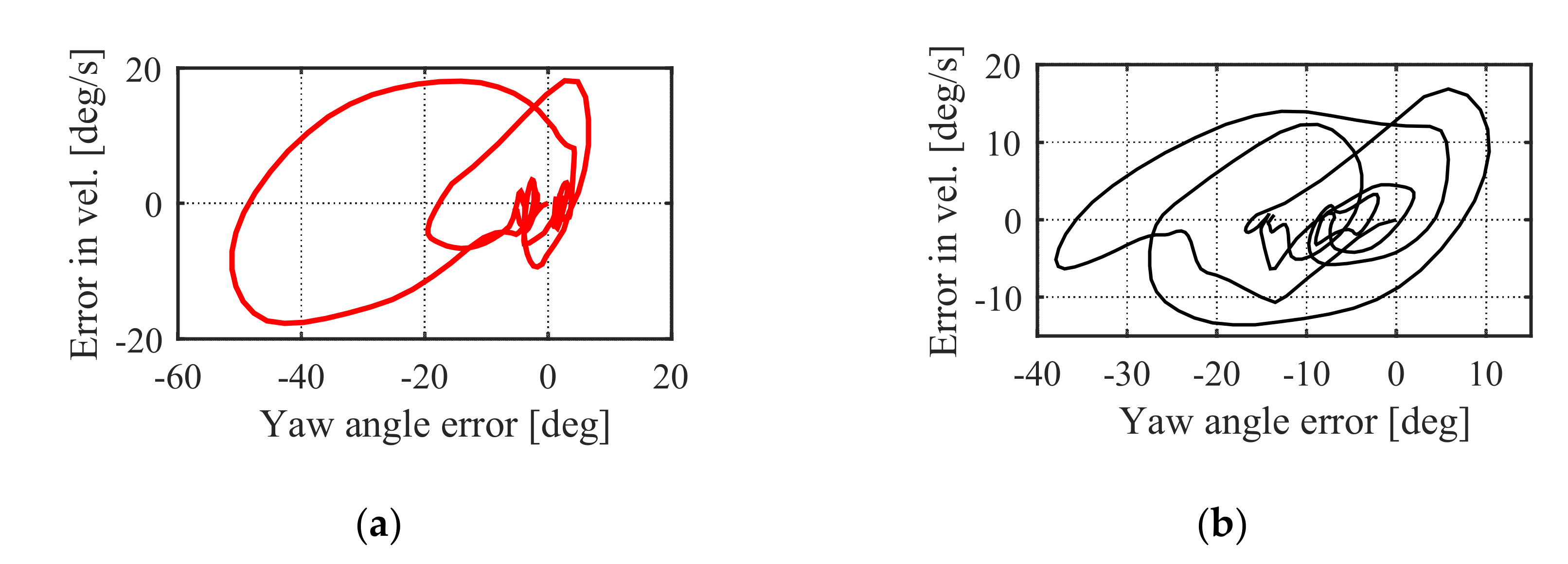
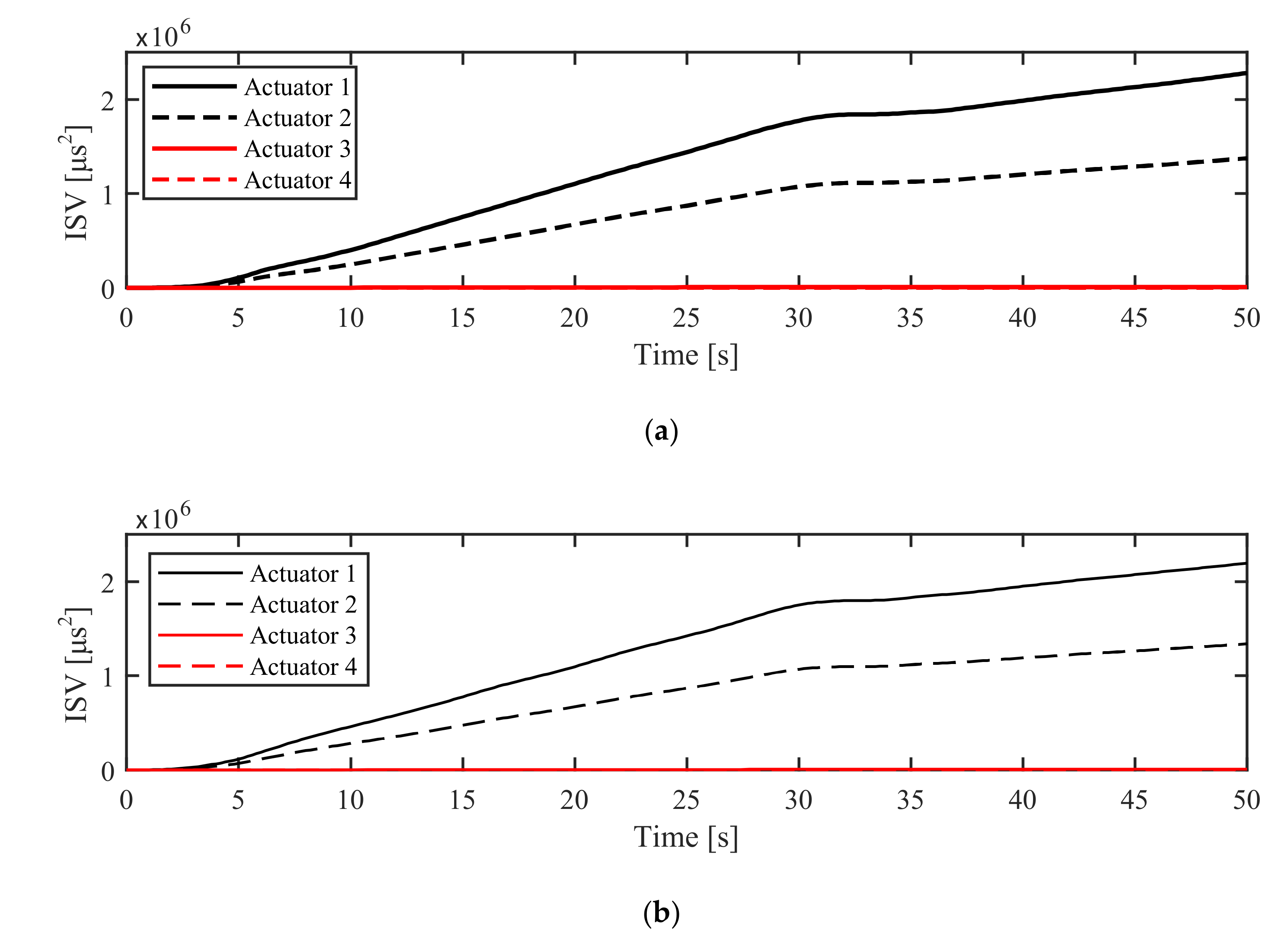
Similarly, the performance results in AM mode are also evaluated by the phase portrait characteristics, RMSE, ITAE, and ISV performance indices. In Figure 16a, the phase portrait of ASTSMC-TDE has a more stable node and stable focus for a small range of position error and velocity error. Meanwhile, the phase portrait of the PID control proves that the system is unstable, as seen in Figure 16b. The ISV values in Figure 17 assert that the proposed controller has less error in the yaw angle compared to the PID controller. Accordingly, the final RMSE, ITAE, and ISV values of both control schemes are listed in Table 2.

6. Experimental Studies

6.1. Experiment Setup

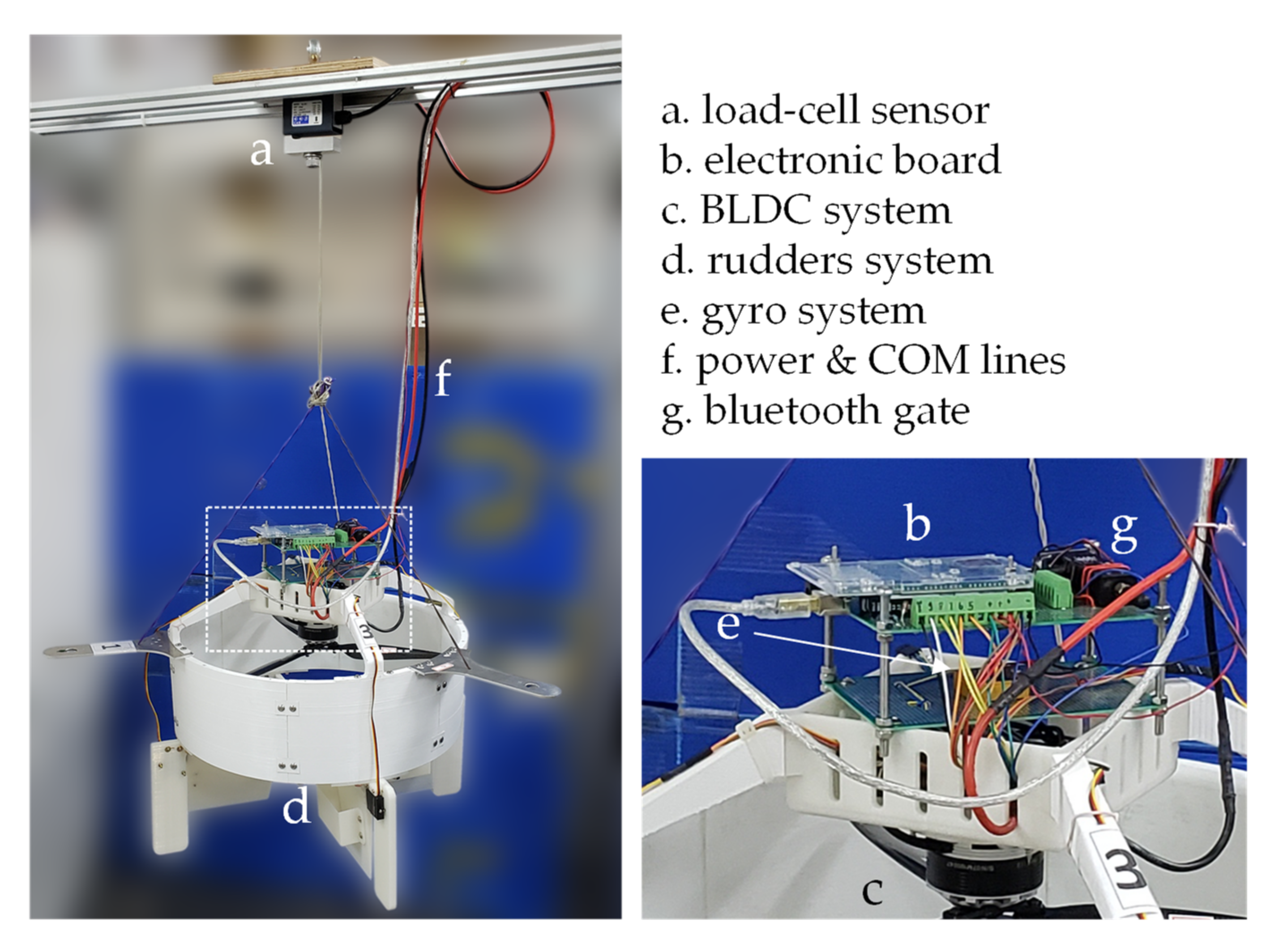
The designed ducted-fan unmanned aerial vehicle is used for the yaw angle motion control experimental study. In a similar fashion to the simulation study, the experiments are also conducted in the NM and the AM modes, which can show the versatility and the practical feasibility of the proposed control scheme. The DUAV is controlled by a LabVIEW PC running on a real-time operating system. The thrust force is generated by a BLDC motor and is measured by a load-cell sensor. The main structure of the DUAV and its parameter specifications are illustrated in Figure 18 and listed in Table 3.

6.2. Experiment Results

6.2.1. Experiment in NM Mode

The efficiency of the proposed ASTSMC-TDE control scheme in Equation (13) has been verified through a set of experiments, and a comparison of its performance with the PID controller was conducted. As aforementioned, both controllers use unchanged control gains during the experiments in NM and AM modes. The ASTSMC-TDE control gains are assigned as K s = d i a g 0.0555 , 0.0555 , 0.0555 , 0.0555 , k s = 2.562 1 , 1 , 1 , 1 T , h s = 1.9001 1 , 1 , 1 , 1 T , and ζ = 500 1 , 1 , 1 , 1 T . The control gains of the ASMC in Equation (16) are chosen as Φ ^ t 0 = 0 , 0 , 0 , 0 T , Ω = d i a g 2 . 5 , 2 . 5 , 2 . 5 , 2 . 5 , the updating error ε = 5 , and the constant δ = 0.9 . For the PID controller gains, the values are k p = 9 . 98825 1 , 1 , 1 , 1 T , k i = 4 . 89544 1 , 1 , 1 , 1 T , and k d = 8.61475 1 , 1 , 1 , 1 T .
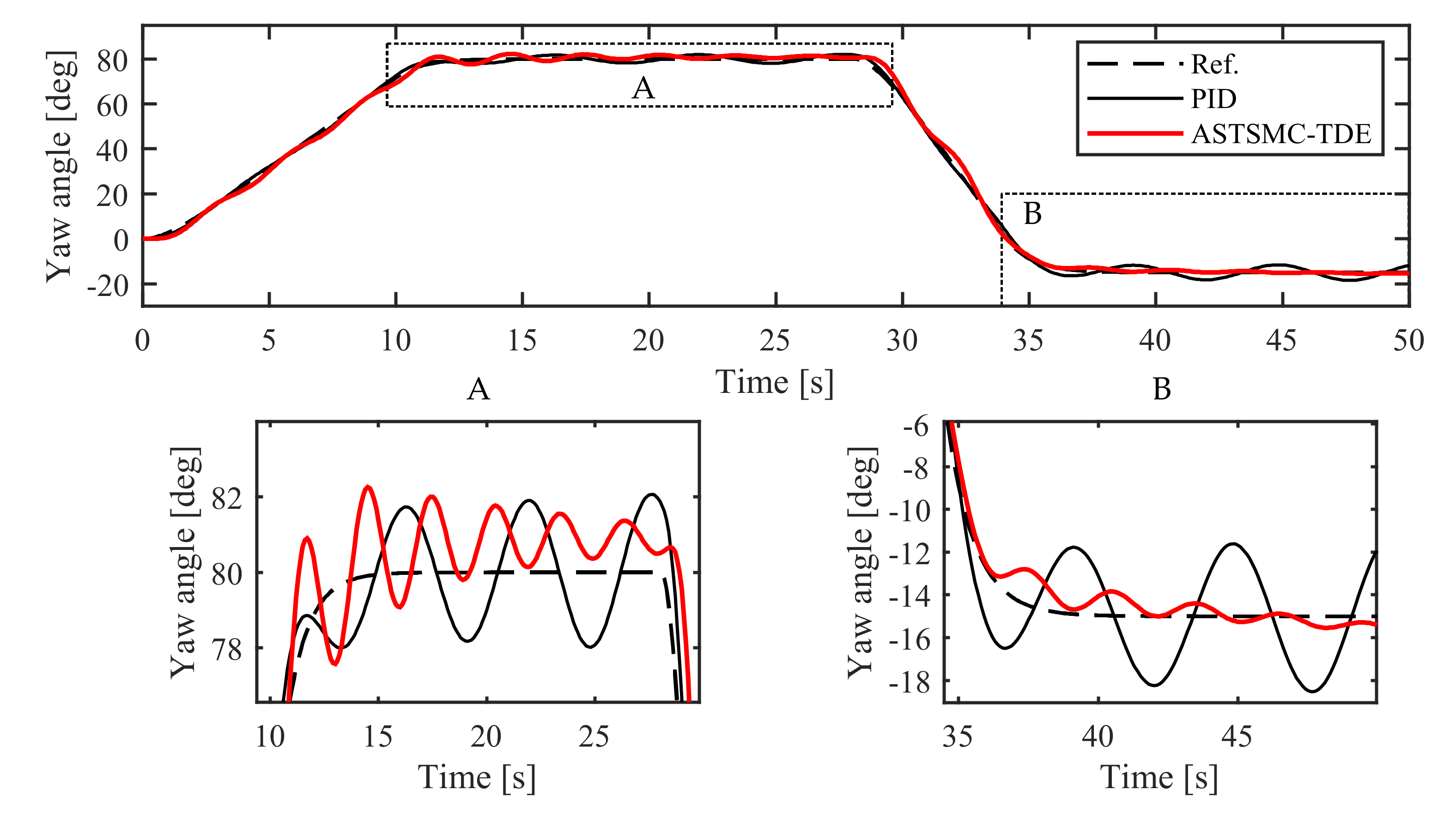
The experiment results of the NM mode are illustrated in Figure 19, Figure 20, Figure 21, Figure 22, Figure 23, Figure 24 and Figure 25. Figure 19 represents the detailed yaw angle response of the DUAV system with both control systems.
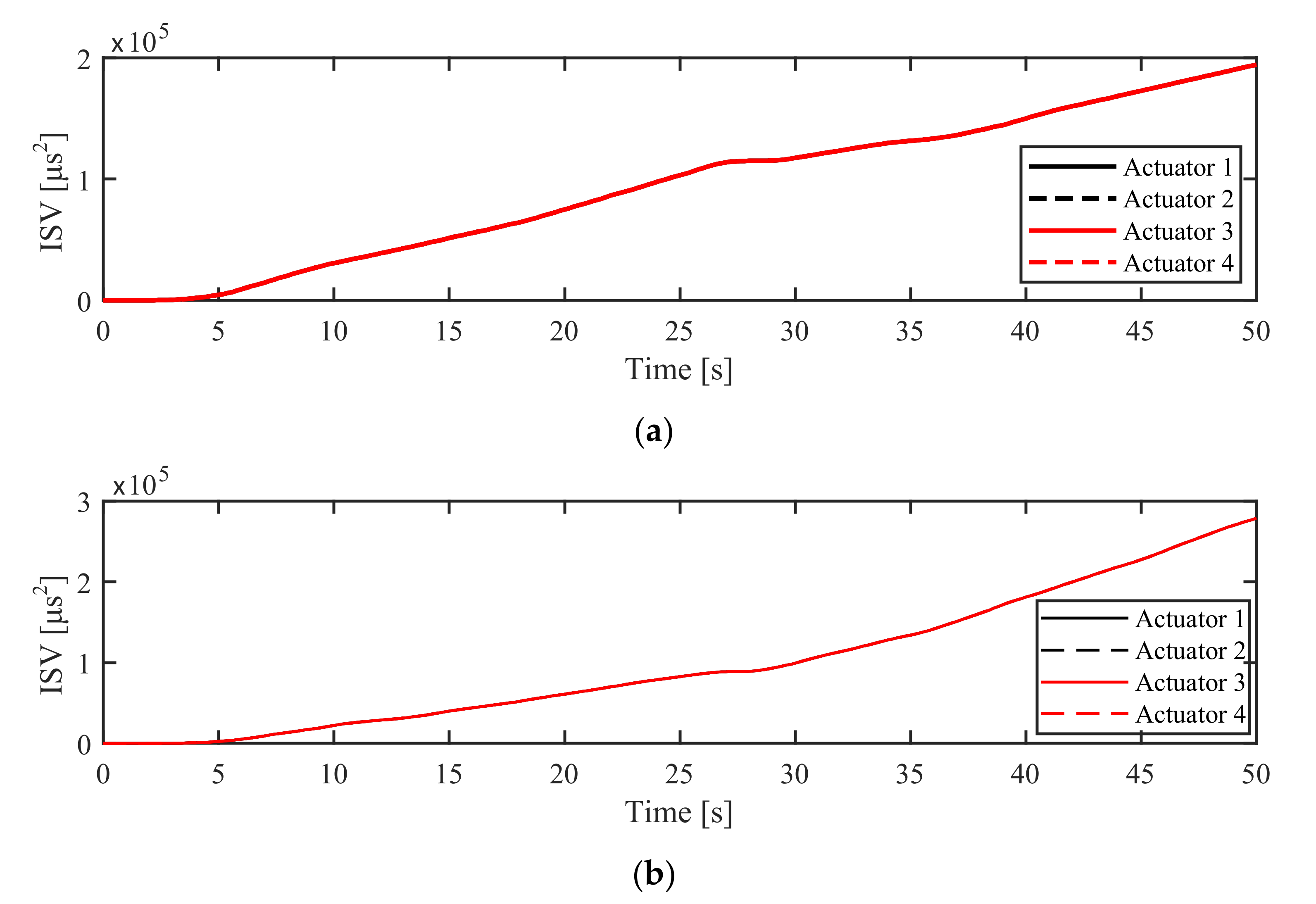
Although the DUAV overshoots slightly at 80 degrees, the tracking error of the ASTSMC-TDE controller is less than that of the PID controller, as depicted in Figure 20. Figure 21 displays the control input obtained from the ASTSMC-TDE and the PID control schemes. The details of their performance are best described with the ISV method, where the energy consumption of both controllers is calculated.
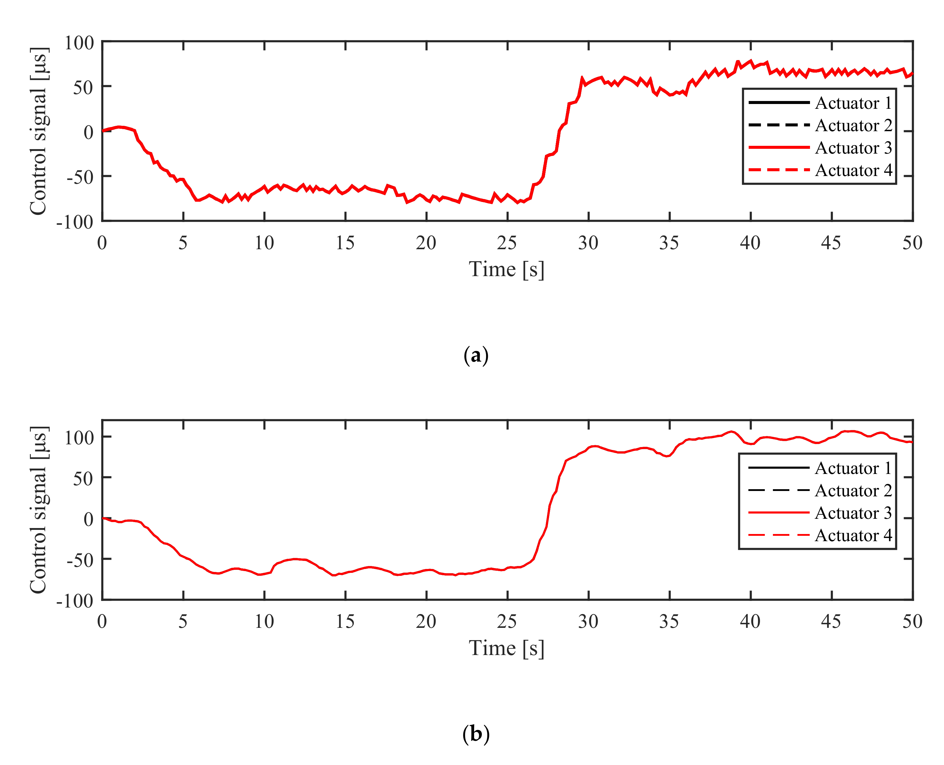
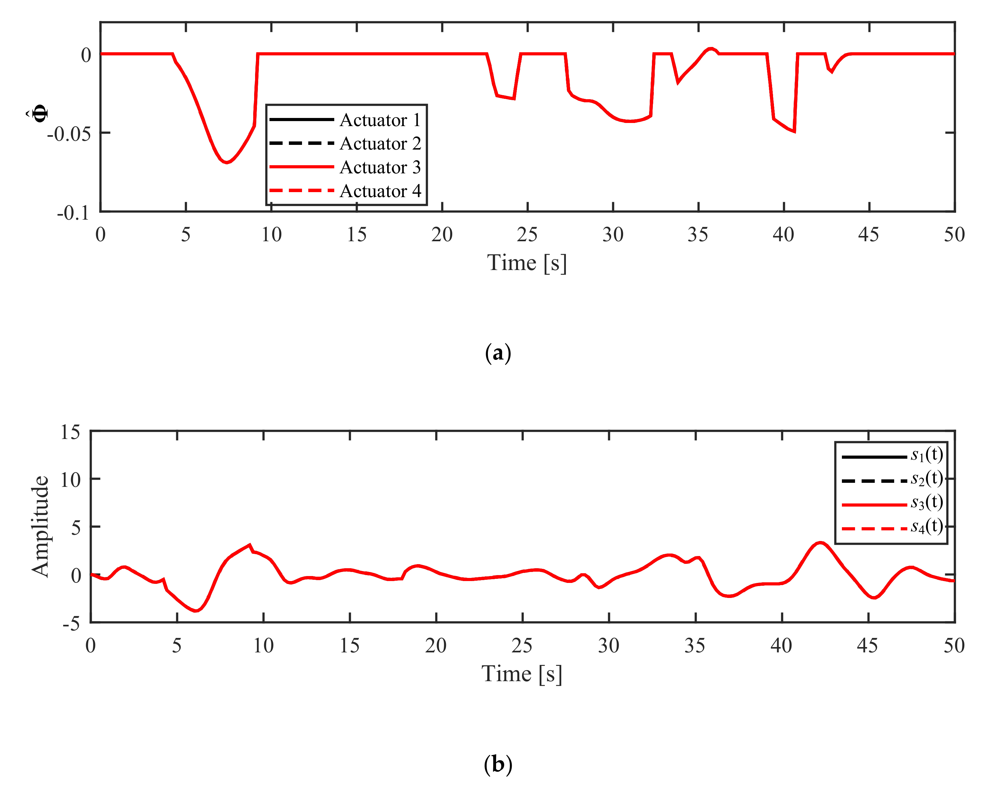
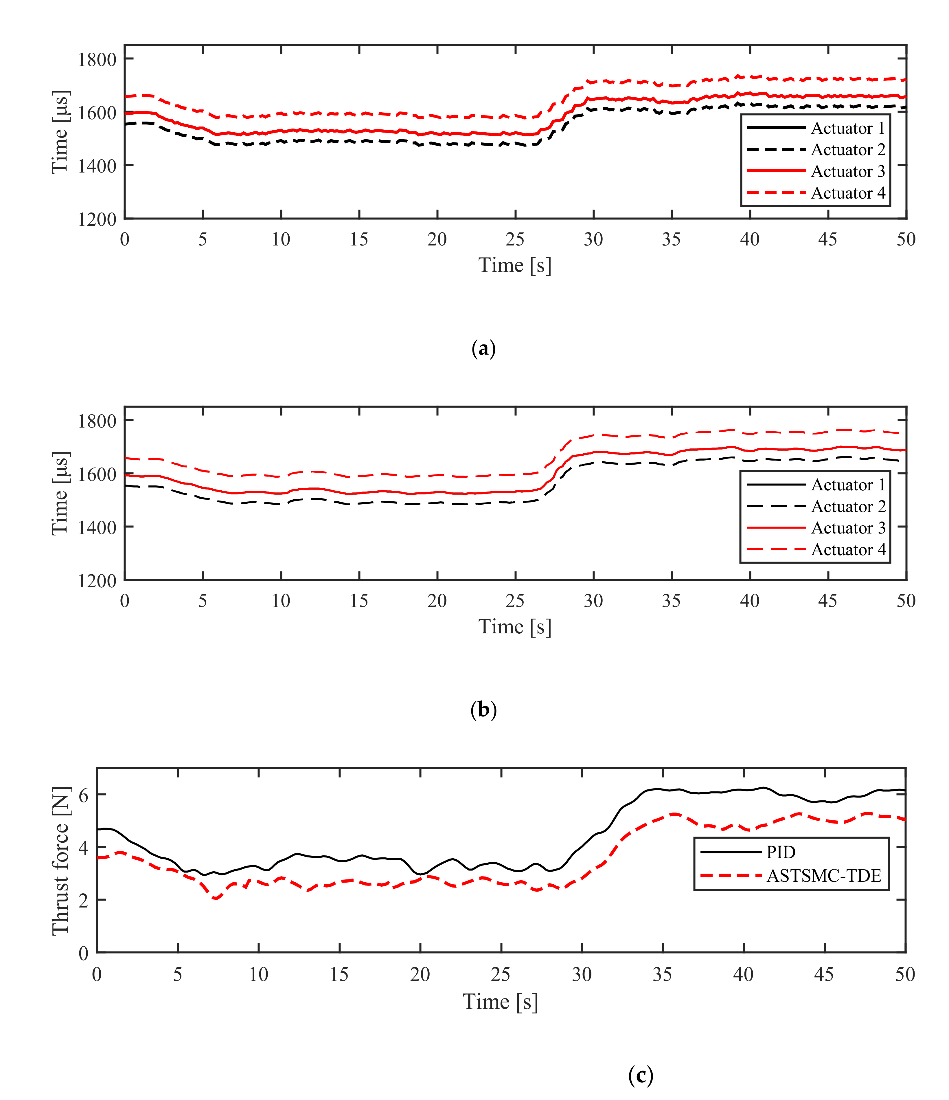
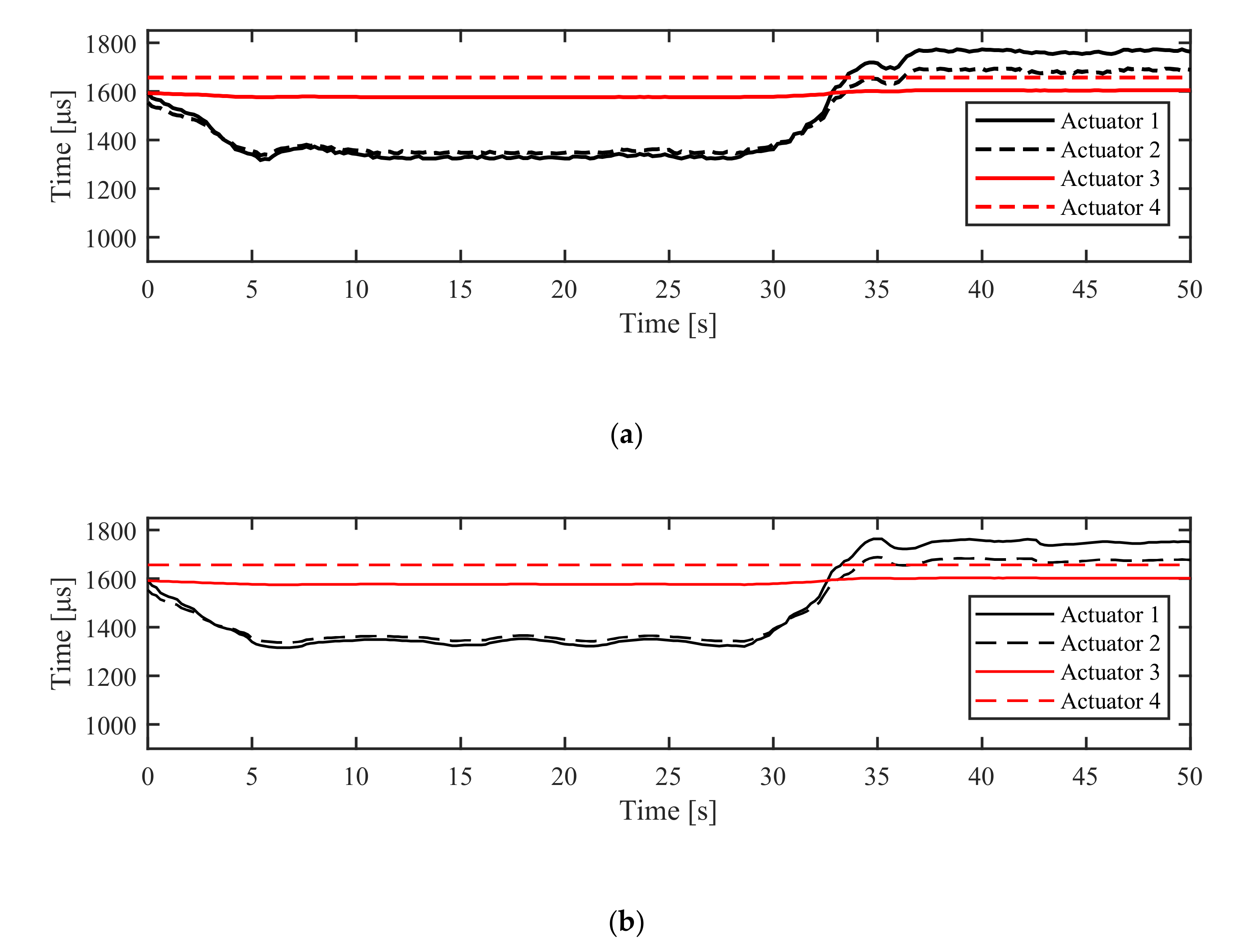
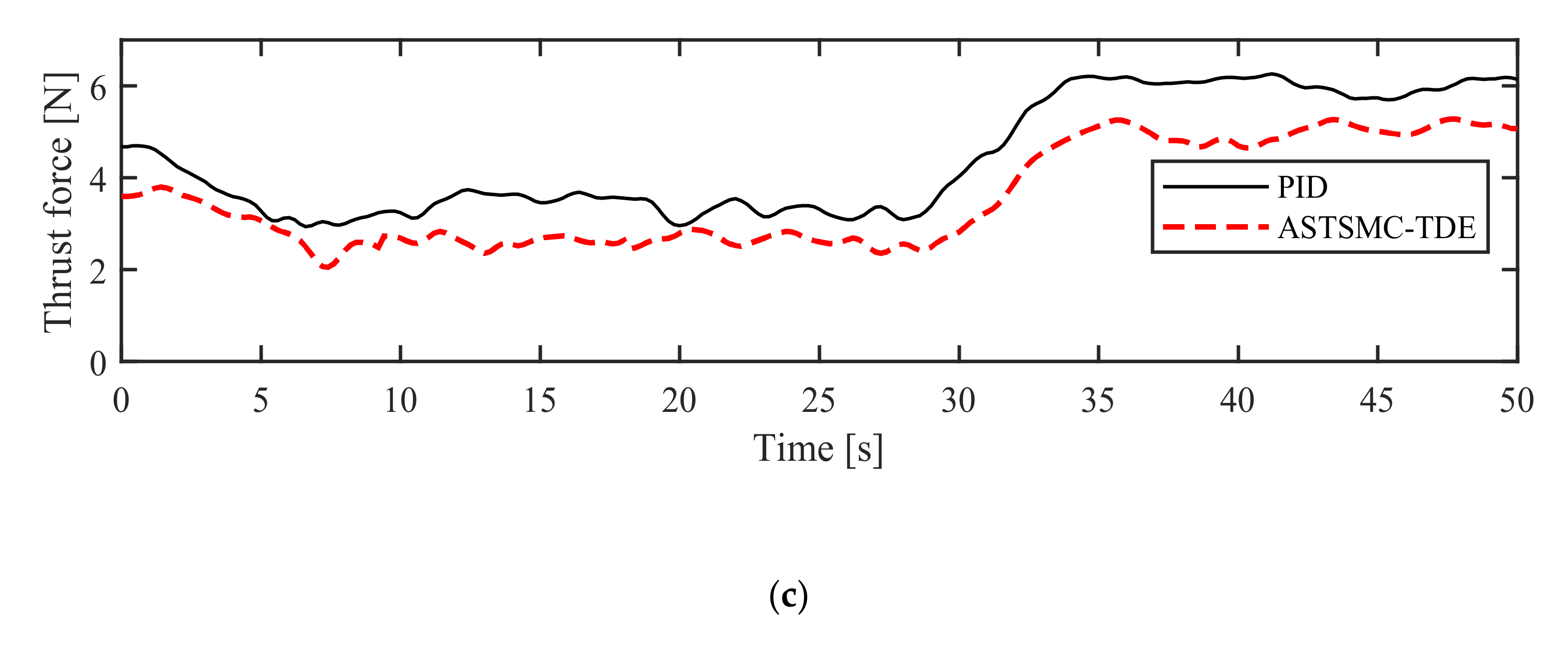
The switching gains of the ASMC term in Equation (16) are proved by Lemma 2 to be bounded by an upper bound, as shown in Figure 22a. The sliding manifold variables in Equation (4) are small and slowly varying, as illustrated in Figure 22b. The control inputs of ASTSMC-TDE and PID to each actuator are represented in Figure 23a,b, respectively. The thrust force generated by the BLDC motor is measured and shown in Figure 23c.
The experiment results are also evaluated with the phase portrait characteristics, the RMSE, the ITAE, and the ISV performance indices. In Figure 24, the phase portraits of both controllers have the same error range. However, the ASTSMC-TDE has a more stable focus than the PID controller.
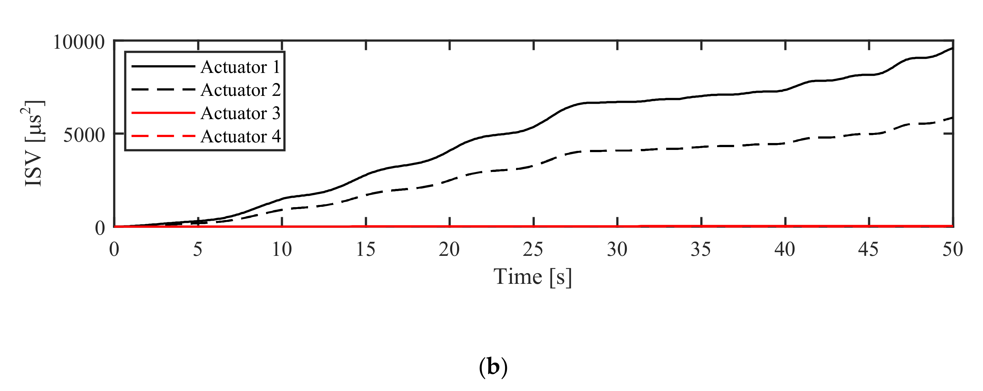
The ISV values of the proposed control system are less than those of the PID controller, as shown in Figure 25. The last RMSE, ITAE, and ISV values of both control schemes are summarized in Table 4. From these results, the system performance has improved by 35.91% in RSME, 36% in ITAE, and 30.27% in ISV when the ASTSMC-TDE controller was implemented.

6.2.2. Experiment in AM Mode

Continuously, the setup in the AM mode is similar to that of the simulation tests. The weighting matrix is tuned as aforementioned, and the experimental results are illustrated in Figure 26, Figure 27, Figure 28, Figure 29, Figure 30, Figure 31 and Figure 32. The practical feasibility of the proposed control scheme in AM mode has been verified through a series of experiments.
The ASTSMC-TDE scheme demonstrates good tracking performances and maintains system stability compared to the PID controller. The ASTSMC-TDE controller has not only the TDE part to cancel the nonlinear factors but also the ASMC term to suppress the resulting TDE errors. Therefore, the error values of the proposed control scheme are smaller than the PID control, as shown in Figure 26 and Figure 27. Figure 28 depicts the detailed control input signals from the ASTSMC-TDE and the PID controls that are evaluated with the ISV performance index.
The updating switching gains of the ASMC are also guaranteed by Lemma 2 to be bounded by upper bounds, as shown in Figure 29a. The control inputs to the actuators of both controllers as well as the thrust force in AM mode are illustrated in Figure 30.
The quality of the experimental results is also evaluated by the phase portrait characteristics, RMSE, ITAE, and the ISV performance indices. The phase portrait of both controllers in Figure 31 shows the same velocity error range. However, ASTSMC-TDE has a stable focus and a stable node. On the contrary, the PID controller is more susceptible to be unstable. The ISV values of the proposed controller are also less than those of the PID controller, as shown in Figure 32. Furthermore, the last RMSE, ITAE, and ISV values of both control systems are listed in Table 5. From the data represented in this table, the system performance has recorded an improvement of 8.26% and 36.59% in RSME and ITAE values, respectively, when the proposed controller was used.

7. Conclusions

A novel ASTSMC-TDE control scheme was proposed and applied to a DUAV system, and its performance is investigated through simulations and experiments. The proposed controller (ASTSMC-TDE) employs a TDE technique to cancel high nonlinearities and an ASMC strategy to suppress the resulting TDE error. On the other hand, the chattering phenomenon is reduced using an approximation of the signum function and the STSMC control configuration. Moreover, the tracking error of DUAV is guaranteed to be UUB based on the Lyapunov stability theory.
A comparison study was conducted between the proposed control scheme and a PID controller in NM and AM modes. This comparative study was executed in both simulation and experiment tests to determine the versatility and practical feasibility of the proposed controller. The quality of the control configurations was verified with performance indices. The performance evaluation of the proposed controller was better than that of the PID controller. For these reasons, the proposed controller had shown good tracking performance and a reduced chattering. Therefore, the proposed ASTSMC-TDE can be considered as a good solution to cope with the high nonlinearities of systems such as DUAVs.

Author Contributions

Conceptualization, formal analysis, methodology, validation, and writing-review and editing, M.-T.T.; writing—editing, S.C.; writing— editing, D.-H.L.; project administration and supervision, Y.-B.K. All authors have read and agreed to the published version of the manuscript.

Funding

This research received no external funding.

Institutional Review Board Statement

Not applicable.

Informed Consent Statement

Not applicable.

Data Availability Statement

Data sharing not applicable.

Conflicts of Interest

The authors declare no conflict of interest.

Appendix A

From Equations (3) and (4), the time derivative of the sliding manifold variable can be written as:
s ˙ t = C ψ c ¯ ψ ψ ¨ d t C ψ K ¯ τ t C ψ Γ t + K s C ψ c ¯ ψ e ˙ t
From Equations (4), (7), and (A1), the time derivative of the Lyapunov equation candidate in Equation (8) can be assigned as:
V ˙ s t = i = 1 n = 4 ξ ˙ i T P i ξ i + ξ i T P i ξ ˙ i V ˙ s t = i = 1 n = 4 1 2 s i t 1 / 2 C ψ i i Γ ^ i t Γ i t 0 + k s i 1 2 h s i 0 ξ i T P i ξ i + 1 2 s i t 1 / 2 ξ i T P i C ψ i i Γ ^ i t Γ i t 0 + k s i 1 2 h s i 0 ξ i V ˙ s t = i = 1 n = 4 s i t 1 / 2 ξ i T P i C ψ i i Γ ^ i t Γ i t 0 + 1 2 s i t 1 / 2 ξ i T k s i 1 2 h s i 0 T P i + P i k s i 1 2 h s i 0 ξ i
V ˙ s t = i = 1 n = 4 s i t 1 / 2 ξ i T P i C ψ i i Γ ^ i t Γ i t 0 1 2 s i t 1 / 2 ξ i T Q i ξ i

Appendix B

The Lyapunov equation candidate is needed to be bounded to prove Lemma 2, [37]. We assume that the Lyapunov function has a sufficiently larger constant value V ˜ as follows:
V t = i = 1 n = 4 ξ i T P i ξ i + 1 2 Γ ˜ i ϕ ^ i t 0 T Ω i i 0 0 Ω i i Γ ˜ i ϕ ^ i t 0 = V ˜
There are two terms in the Lyapunov function candidate of Equation (A3), however, there is at least one term that should be sufficiently large. First, the time derivative of the Lyapunov function candidate is negative following Equation (21) if s t 2 2 is sufficiently large.
If the term 1 2 Γ ˜ i ϕ ^ i t 0 T Ω i i 0 0 Ω i i Γ ˜ i ϕ ^ i t 0 of the Lyapunov function candidate is sufficiently large, then its time derivative is also negative if considered as following:
Γ ˜ Φ ^ t
1 2 Γ ˜ i ϕ ^ i t 0 T Ω i i 0 0 Ω i i Γ ˜ i ϕ ^ i t 0 = Π V ˜ , Γ 0 , Φ ^ t 0
where Π is a sufficiently large number less than or equal to V ˜ . Equation (A4) provides a negative value since Π is a sufficiently large number.
In both cases, one of two terms in Equation (A3) is significantly large, V ˙ t 0 . However, V t has the value V ˜ , the time derivative of V t is semi-negative. It means that V t cannot exceed V ˜ . Therefore, V t is uniformly ultimately bounded and Φ ^ t is also upper bounded for t 0 as follows:
Φ ^ t Φ ˜

Appendix C

Taking the time derivative of the Lyapunov candidate in Equation (17), we obtain:
V ˙ t = i = 1 n = 4 ξ ˙ i T P i ξ i + ξ i T P i ξ ˙ i + 1 2 ϕ ^ ˙ i t 0 T Ω i i 0 0 Ω i i Γ ˜ i ϕ ^ i t 0 + Γ ˜ i ϕ ^ i t 0 T Ω i i 0 0 Ω i i ϕ ^ ˙ i t 0 V ˙ t = i = 1 n = 4 ξ ˙ i T P i ξ i + ξ i T P i ξ ˙ i + Γ ˜ i ϕ ^ i t 0 T Ω i i 0 0 Ω i i ϕ ^ ˙ i t 0

Appendix D

Substituting Lemma 1 into Equation (20), we can rearrange the time derivative of the Lyapunov function as follows:
V ˙ t i = 1 n = 4 1 2 s i t 1 / 2 ξ i T Q i ξ i + s i t 1 / 2 ξ i T P i C ψ i i Γ ˜ i C ψ i i ϕ ^ i t 0 + Λ i t = i = 1 n = 4 1 2 s i t 1 / 2 ξ i T Q i ξ i + s i t 1 / 2 P i ξ i C ψ i i T Γ ˜ i ϕ ^ i t 0 + Γ ˜ i ϕ ^ i t 0 T Ω i i 0 0 Ω i i ϕ ^ ˙ i t 0 = i = 1 n = 4 1 2 s i t 1 / 2 ξ i T Q i ξ i + Γ ˜ i ϕ ^ i t 0 T s i t 1 / 2 P i ξ i C ψ i i + Ω i i 0 0 Ω i i ϕ ^ ˙ i t 0

References

  1. Jo, D.; Kwon, Y. Analysis of VTOL UAV Propellant Technology. J. Comput. Commun. 2017, 5, 76–82. [Google Scholar] [CrossRef] [Green Version]
  2. Akturk, A.; Camci, C. Tip Clearance Investigation of a Ducted Fan Used in VTOL Unmanned Aerial Vehicles—Part I: Baseline Experiments and Computational Validation. J. Turbomach. 2014, 136, 0210041–02100410. [Google Scholar] [CrossRef]
  3. Akturk, A.; Camci, C. Tip Clearance Investigation of a Ducted Fan Used in VTOL Unmanned Aerial Vehicles—Part II: Novel Treatments via Computational Design and Their Experimental Verification. J. Turbomach. 2014, 136, 0210051–02100510. [Google Scholar] [CrossRef]
  4. Fan, W.; Xiang, C.; Xu, B. Modelling, Attitude Controller Design and Flight Experiments of a Novel Micro-ducted-fan Aircraft. SAGE Adv. Mech. Eng. 2018, 10, 1–16. [Google Scholar] [CrossRef] [Green Version]
  5. Sheng, S.; Sun, C. A Near-hover Adaptive Attitude Control Strategy of a Ducted Fan Micro Aerial Vehicle with Actuator Dynamics. Appl. Sci. 2015, 5, 666–681. [Google Scholar] [CrossRef] [Green Version]
  6. Mahony, R.; Hamel, T.; Pflimlin, J.M. Nonlinear Complementary Filters on the Special Orthogonal Group. IEEE Trans. Autom. Control 2008, 53, 1203–1218. [Google Scholar] [CrossRef] [Green Version]
  7. Jiang, Y.; Zhang, B.; Huang, T. CFD Study of an Annular-ducted Fan Lift System for VTOL Aircraft. Aerospace 2015, 2, 555–580. [Google Scholar] [CrossRef] [Green Version]
  8. Choi, Y.H.; Suk, J.; Hong, S.H. Static Analysis of a Small Scale Ducted-fan UAV Using Wind Tunnel Data. Int. J. Aeronaut. Space Sci. 2012, 13, 34–42. [Google Scholar] [CrossRef]
  9. Gelhausen, P.; Enns, D. Improving Control System Effectiveness for Ducted Fan VTOL UAVs Operating in Crosswinds. In Proceedings of the 2nd AIAA “Unmanned Unlimited” Systems, Technologies, and Operations—Aerospace, San Diego, CL, USA, 15–18 September 2003. [Google Scholar]
  10. Naldi, R.; Gentili, L.; Marconi, L.; Sala, A. Design and Experimental Validation of a Nonlinear Control Law for a Ducted-fan Miniature Aerial Vehicle. Elsevier Control Eng. Pract. 2010, 18, 747–760. [Google Scholar] [CrossRef]
  11. Lipera, L.; Colbourne, J.D.; Rotkowitz, M.C.; Patangui, P. The Micro Craft iSTAR Micro Air Vehicle: Control System Design and Testing. In Proceedings of the American Helicopter Society 57th Annual forum, Washington, DC, USA, 9–11 May 2001. [Google Scholar]
  12. Ko, A.; Ohanian, O.J.; Gelhausen, P. Ducted Fan UAV Modeling and Simulation in Preliminary Design. In Proceedings of the AIAA Modeling and Simulation Technologies Conference and Exhibit, Hilton Head, SC, USA, 20–23 August 2007. [Google Scholar]
  13. Muehlebach, M.; D’Andrea, R. The Flying Platform–A Testbed for Ducted Fan Actuation and Control Design. Elsevier Mechatron. 2017, 42, 52–68. [Google Scholar] [CrossRef]
  14. Spurgeon, S.K. Sliding Mode Observers: A survey. Int. J. Syst. Sci. 2008, 39, 751–764. [Google Scholar] [CrossRef]
  15. Mironova, A.; Mercorelli, P.; Zedler, A. A multi Input Sliding Mode Control for Peltier Cells Using a Cold-hot Sliding Surface. Elsevier J. Frankl. Inst. 2018, 355, 9351–9373. [Google Scholar] [CrossRef]
  16. Hsia, T.C.; Lasky, T.A.; Guo, Z. Robust Independent Joint Controller Design for Industrial Robot Manipulators. IEEE Trans. Ind. Electron. 1991, 38, 21–25. [Google Scholar] [CrossRef]
  17. Jin, M.; Kang, S.H.; Chang, P.H.; Lee, J. Robust Control of Robot Manipulators Using Inclusive and Enhanced Time delay Control. IEEE ASME Trans. Mechatron. 2017, 22, 2141–2152. [Google Scholar] [CrossRef]
  18. Youcef-Toumi, K.; Ito, O. A Time Delay Controller for Systems with Unknown Dynamics. ASME J. Dyn. Syst. Meas. Control 1990, 112, 133–142. [Google Scholar] [CrossRef]
  19. Hua, M.D.; Hamel, T.; Morin, P.; Samson, C. Introduction to Feedback Control of Underactuated VTOL Vehicles. IEEE Control Syst. Mag. 2013, 33, 61–75. [Google Scholar]
  20. Filipescu, A.; Mincă, E.; Filipescu, A.; Coandă, H.G. Manufacturing Technology on a Mechatronics Line Assisted by Autonomous Robotic Systems, Robotic Manipulators and Visual Servoing Systems. Actuators 2020, 9, 127. [Google Scholar] [CrossRef]
  21. Aggumus, H.; Guclu, R. Robust H Control of STMDs Used in Structural Systems by Hardware in the Loop Simulation Method. Actuators 2020, 9, 55. [Google Scholar] [CrossRef]
  22. Li, B.; Zhou, W.; Sun, J.; Wen, C.Y.; Chen, C.K. Development of Model Predictive Controller for a Tail-sitter VTOL UAV in Hover Flight. Sensors 2018, 18, 2859. [Google Scholar] [CrossRef] [Green Version]
  23. Enders, E.; Burkhard, G.; Munzinger, N. Analysis of the Influence of Suspension Actuator Limitations on Ride Comfort in Passenger Cars Using Model Predictive Control. Actuators 2020, 9, 77. [Google Scholar] [CrossRef]
  24. Edwards, C.; Spurgeon, S.K. Sliding Mode Control Theory and Applications; International Ltd: Padstow, UK, 1998. [Google Scholar]
  25. Levant, A. Sliding Order and Sliding Accuracy in Sliding Mode Control. Int. J. Control 1993, 58, 1247–1263. [Google Scholar] [CrossRef]
  26. Barth, A.; Reichhartinger, M.; Reger, J.; Horn, M.; Wulff, K. Lyapunov-design for a Super-twisting Sliding-mode Controller Using the Certainty-equivalence Principle. Elsevier Int. Fed. Autom. Control 2015, 48, 860–865. [Google Scholar] [CrossRef]
  27. Tran, M.T.; Kim, K.H.; Park, H.C.; Kim, Y.B. A Study on an Adaptive Super-twisting Sliding Mode Control Design with Perturbation Estimation. J. Power Syst. Eng. 2020, 24, 53–63. [Google Scholar] [CrossRef]
  28. Huynh, T.; Kim, Y.B. A Study on Gimbal Motion Control System Design Based on Super-twisting Control Method. J. Korean Soc. Precis. Eng. 2021, 38, 115–122. [Google Scholar] [CrossRef]
  29. Humaidi, A.J.; Hasan, A.F. Particle Swarm Optimization-based Adaptive Super-twisting Sliding Mode Control Design for 2-degree-of-freedom Helicopter. Sage Meas. Control 2019, 52, 1–17. [Google Scholar] [CrossRef] [Green Version]
  30. Morioka, H.; Wada, K.; Sabanovic, A. Sliding Mode Control Based on the Time Delay Estimation. IEEE Workshop Var. Struct. Syst. 1996, 102–107. [Google Scholar]
  31. Tseng, M.L.; Chen, M.S. Chattering Reduction of Sliding Mode Control by Low-pass Filtering the Control Signal. Asian J. Control 2010, 12, 392–398. [Google Scholar] [CrossRef]
  32. Cho, G.R.; Chang, P.H.; Park, S.H.; Jin, M. Robust Tracking Under Nonlinear Friction Using Time-delay Control with Internal Model. IEEE Trans. Control Syst. Technol. 2009, 17, 1406–1414. [Google Scholar]
  33. Lee, J.; Chang, P.H.; Jin, M. An Adaptive Gain Dynamics for Time Delay Control Improves Accuracy and Robustness to Significant Payload Changes for Robots. IEEE Trans. Ind. Electron. 2020, 67, 3076–3085. [Google Scholar] [CrossRef]
  34. Jin, M.; Jin, Y.; Chang, P.H.; Choi, C. High-accuracy Trajectory Tracking of Industrial Robot Manipulators Using Time Delay Estimation and Terminal Sliding Mode. In Proceedings of the 35th Annual Conference of IEEE Industrial Electronics, Porto, Portugal, 3–5 November 2009. [Google Scholar]
  35. Youcef-Toumi, K.; Ito, O. A Time Delay Controller for Systems with Unknown Dynamics. In Proceedings of the 1988 American Control Conference, Atlanta, GA, USA, 15–17 June 1988. [Google Scholar]
  36. Zheng, G.; Polyakov, A.; Levant, A. Delay Estimation via Sliding Mode for Nonlinear Time-delay System. Elsevier Autom. 2018, 2018, 266–273. [Google Scholar] [CrossRef]
  37. Baek, J.; Jin, M.; Han, S. A New Adaptive Sliding-mode Control Scheme for Application to Robot Manipulators. IEEE Trans. Ind. Electron. 2016, 63, 3628–3637. [Google Scholar] [CrossRef]
  38. Lavretsky, E.; Wise, K.A. Robust and Adaptive Control with Aerospace Applications; Springer: London, UK, 2013. [Google Scholar]
  39. Cook, M.V. Flight Dynamics Principles, 2nd ed.; Elsevier Ltd.: Cambridge, MA, USA, 2007. [Google Scholar]
  40. Caro-Lopera, F.J.; Leiva, V.; Balakrishnan, N. Connection Between the Hadamard and Matrix Products with an Application to Matrix-variate Birnbaum–Saunders Distributions. Elsevier J. Multivar. Anal. 2012, 104, 126–139. [Google Scholar] [CrossRef] [Green Version]
  41. Styan, G.P.H. Hadamard Products and Multivariate Statistical Analysis. Linear Algebra Its Appl. 1973, 6, 217–240. [Google Scholar] [CrossRef] [Green Version]
  42. Moreno, J.A.; Osorio, M. Strict Lyapunov Functions for the Super-Twisting Algorithm. IEEE Trans. Autom. Control 2012, 57, 1035–1040. [Google Scholar] [CrossRef]
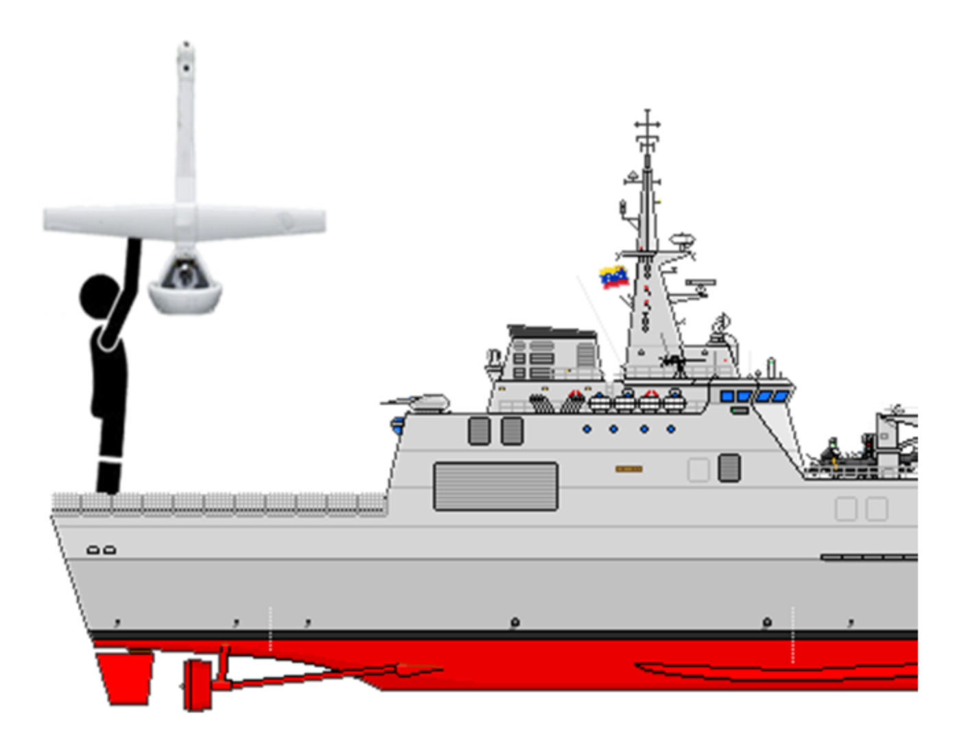
Figure 1. The manual landing process of the DUAV system on a ship deck.
Actuators 10 00054 g001
Figure 2. The yaw angle motion control of the designed DUAV model: (a) The yaw angle control process before the landing; (b) The structure of the DUAV model.
Actuators 10 00054 g002
Figure 3. Schematic of the rudders and actuators and their corresponding order.
Actuators 10 00054 g003
Figure 4. Block diagram of the proposed controller (ASTSMC – TDE).
Actuators 10 00054 g004
Figure 5. The desired yaw angle trajectory.
Actuators 10 00054 g005
Figure 6. Simulation results of the yaw angle trajectory tracking in NM mode.
Actuators 10 00054 g006
Figure 7. The yaw angle errors.
Actuators 10 00054 g007
Figure 8. The control signal: (a) Proposed controller; (b) PID.
Actuators 10 00054 g008
Figure 9. The performance of the proposed controller: (a) Updating switching gains of the ASTSMC-TDE (ASMC term); (b) Sliding manifold variables.
Actuators 10 00054 g009
Figure 10. The phase-portrait: (a) Proposed controller; (b) PID.
Actuators 10 00054 g010
Figure 11. The performance indices: (a) ISV values of the proposed controller; (b) ISV values of the PID.
Actuators 10 00054 g011aActuators 10 00054 g011b
Figure 12. Simulation results of the yaw angle trajectory tracking in AM mode.
Actuators 10 00054 g012
Figure 13. The yaw angle errors in AM mode.
Actuators 10 00054 g013
Figure 14. The control signal in AM mode: (a) Proposed controller; (b) PID.
Actuators 10 00054 g014
Figure 15. The performance of the proposed controller in AM mode: (a) The updating switching gains of ASTSMC-TDE (ASMC term); (b) Sliding manifold variables.
Actuators 10 00054 g015
Figure 16. The phase-portrait in AM mode: (a) Proposed controller; (b) PID.
Actuators 10 00054 g016
Figure 17. The performance indices in AM mode: (a) ISV values of the proposed controller; (b) ISV values of the PID.
Actuators 10 00054 g017aActuators 10 00054 g017b
Figure 18. The experimental setup of the ducted fan unmanned aerial vehicle (DUAV).
Actuators 10 00054 g018
Figure 19. Experimental results of the yaw angle trajectory tracking in NM mode.
Actuators 10 00054 g019
Figure 20. The experimental yaw angle error in NM mode.
Actuators 10 00054 g020
Figure 21. The experimental control signal: (a) Proposed controller; (b) PID.
Actuators 10 00054 g021
Figure 22. The performance of the proposed controller in NM mode: (a) Updating switching gains of the ASTSMC-TDE (ASMC term); (b) Sliding manifold variables.
Actuators 10 00054 g022
Figure 23. The experimental performance of the actuators in NM mode: (a) Control gains of actuators with the proposed controller; (b) Control gains of the actuators with the PID; (c) Thrust force generated by the BLDC.
Actuators 10 00054 g023
Figure 24. The experimental phase-portrait: (a) Proposed controller; (b) PID.
Actuators 10 00054 g024
Figure 25. The performance indices: (a) ISV values of the proposed controller; (b) ISV values of the PID.
Actuators 10 00054 g025
Figure 26. The experimental yaw angle trajectory tracking in AM mode.
Actuators 10 00054 g026
Figure 27. The experimental yaw angle error in AM mode.
Actuators 10 00054 g027
Figure 28. The experimental control signal in AM mode: (a) Proposed controller; (b) PID.
Actuators 10 00054 g028
Figure 29. The performance of the proposed controller: (a) The updating switching gains of the ASTSMC-TDE (ASMC term); (b) Sliding manifold variables.
Actuators 10 00054 g029
Figure 30. The experimental performance of the actuators in NM mode: (a) The control gains of actuators with the proposed controller; (b) Control gains of actuators with the PID; (c) Thrust force generated by BLDC.
Actuators 10 00054 g030aActuators 10 00054 g030b
Figure 31. The experimental phase-portrait in AM mode: (a) Proposed controller; (b) PID.
Actuators 10 00054 g031
Figure 32. The performance indices in experimental AM mode: (a) ISV values of the proposed controller; (b) ISV values of the PID.
Actuators 10 00054 g032
Table 1. RMSE, ITAE, and ISV values in NM mode.
RMSE [deg]ITAE [s.deg]ISV [μs2]
ASTSMC-TDE1.54225.49771635.1
1635.1
1635.1
1635.1
PID1.64696.96111392
1392
1392
1392
Table 2. RMSE, ITAE, and ISV values in AM mode.
RMSE [deg]ITAE [s.deg]ISV [μs2]
ASTSMC-TDE2.01147.02817507
3569.8
1051.7
0
PID6.754924.96299597.4
5857.8
37.49
0
Table 3. The specification of DUAV apparatus.
DevicesSpecification Parameters
Hover diameterd = 410 [mm]
Propeller diameterdp = 393.7 [mm]
BLDC powerP = 2.4 [kW]
DUAV massm = 2.01132 [kg]
Communication method of Arduino boardRS-232 (COM)
Communication method of the gyro sensorBluetooth
I/O devicesArduino Mega 2560
Control softwareLabview 2016
Load-cell sensor (max)F = 20 [kgf] ~ Vout = 10 [V]
Gyro sensor± 2000 (0/s)
Servo motor0.17sec 600 at 4.8[V]
Table 4. RMSE, ITAE, and ISV experimental values in NM mode.
RMSE [deg]ITAE [s.deg]ISV [μs2]
ASTSMC-TDE6.875341.05081.9437 × 105
1.9437 × 10⁵
1.9437 × 10⁵
1.9437 × 10⁵
PID10.727764.15182.7873 × 105
2.7873 × 10⁵
2.7873 × 10⁵
2.7873 × 10⁵
Table 5. RMSE, ITAE, and ISV values in experimental AM mode.
RMSE [deg]ITAE [s.deg]ISV [μs2]
ASTSMC-TDE13.725475.9322.2801 × 106
1.3751 × 10⁶
9.4316 × 10³
0
PID14.9606119.74652.1967 × 106
1.3395 × 10⁶
8.5648 × 10³
0
Publisher’s Note: MDPI stays neutral with regard to jurisdictional claims in published maps and institutional affiliations.