Abstract
A simulated space manipulator is designed to verify the reliability of the zero-gravity simulation system, which can avoid the risks of experiments involving the space manipulator in this zero-gravity ground system. To achieve similarity between the simulated and actual space manipulators, the mass, barycenter, and inertia must be considered. In this study, a counterweight component is designed and an optimization method is used to match the mass parameters of the simulated joints to those of the space joints. In addition, an equivalence method is used to establish the relationship between the torques of these two manipulators.
1. Introduction
The space manipulator is a high level of integrated space of mechanical and electrical systems in mechanical, electrical, thermal, and control fields. The space environment is harsh and it is a zero-gravity condition. Thus, a space manipulator must be completely analyzed and pass all the verification tests in a zero-gravity simulation system on the ground before it operates on-orbit.
The simulation systems should simulate the zero-gravity condition and allow motions of the space manipulator. They can be divided into five types according to their working principles [1,2]: (1) Free fall: It uses gravity acceleration to realize a zero-gravity environment. A drop tower designed by the University of Stuttgart and Baylor University, which can provide 1.5 s in free fall duration a quality of g [3]; (2) Parabolic flight: It uses gravity to perform a parabolic trajectory and achieve microgravity condition. A specially-modified Airbus A310-300 aircraft is flied by The European Space Agency for a total of 10 min of weightlessness per flight [4]; (3) Neutral buoyancy: The manipulators are placed in a water environment, such as the neutral buoyancy facility at University of Maryland [5]; (4) Air-bearing system. It is the most widely used method to achieve zero-gravity. The air bearing pads support the manipulator and balance the gravity force. The main arm of the Japanese Experiment Module Remote Manipulator System (JEMRMS) has been tested on an air bearing test bed [6]; and (5) suspension system. The suspension force compensates the gravity force. Carnegie Mellon University designed a gravity compensation system for their Self Mobile Space Manipulator (SM) [7]. Each zero-gravity system has advantages and disadvantages, and scholars should select the testing system carefully according to the actual situation.
Because of the large motions and the multiple Degree of Freedom (DOF) of the manipulator, an active compensation suspension system is used as the zero-gravity simulation system in this study. A constant-tension suspension for space manipulators was developed by Fujitsu Laboratories (Fujitsu Ltd. Kawasaki, Japan) first [8]. The tension force was provided by a motor instead of the counterweight mechanism. Liu et al. [9] used a single wire to achieve the gravitation of the moon for the Rocker-bogie Rover. The Gravity compensation model is established as well. Shen et al. [10] designed a system for physically simulating human walking in microgravity using such a method. The suspension system can be divided into two distinct parts [11]: a constant tension force system and a follow-up system. The tension force system affords vertical constant forces, which can be controlled to balance the gravity force. The follow-up system guarantees the tension force is vertical whatever the attitude of the manipulator. However, in an actual experiment, the tension forces cannot be always constant. Thus, the gravity of the manipulator cannot be balanced completely, causing additional torques to be exerted in the joints. To ensure the reliability of the experiments, it is necessary to analyze the additional torques of the joints.
Several experiments must be conducted to verify the zero-gravity simulation system after the primary design of the system. It is costly and unreliable to use the actual space manipulator directly. Consequently, it is essential to design a simulated manipulator is designed to replace the space manipulator for the initial experiments. When the system is tested completely, the space manipulator can be experimented in it. Equivalent test models are widely used in the aerospace field. We can predict the conditions of the actual ones by testing on the models. Kuroda et al. [12] produced two experimental models of the planetary rover to test in a low-gravity flight. Yao et al. [13] presented a method to solve the added mass of a robot tested in neutral buoyancy, which made the model and the actual robot be similar. In our study, the structures and masses of the joints of the simulated manipulator differ from the space ones. To assure the consistency in the kinematics and dynamics, the mass, barycenter, and inertia of the simulated manipulator must be matched [14]. Hou et al. [14] proposed a dynamic programming to match the barycenter of a microsatellite, which can guarantee the dynamic balance of the satellite. You et al. [15] used the genetic algorithm (GA) to optimize the mass-matching on a reentry vehicle. It can ensure the complex requirements of mass parameters by using the least counterweight. However, most of the present researches consider the barycenter only, and the mass of the counterweight can be changed. In this study, the total mass of the joint is constant, which increases the difficulty of mass-matching. Moreover, the errors that are inevitably introduced after matching should be evaluated. Ijar et al. [16] indicated that the spacecraft is sensitive to any reaction force and torque for its zero-gravity operating condition. They established the dynamic equations of a spacecraft by using Lagrange’s formulas. Alepuz et al. [17] derived the kinematic and dynamic equations of a free-floating satellite-mounted robot (FFSMR), which contains a series manipulator and a satellite. Masuya et al. [18] proposed a novel technique to estimate motion of the barycenter for a biped robot based on its torque equilibrium. In a similar way, the torque can becalculated based on the motion of the barycenter.
In this study, a method is designed to match the mass and barycenter of the joint of the simulated manipulator. The counterweight components are used to adjust the masses and barycenters of the simulated joints for agreement with the space ones. In addition, the equivalence relationship between the mass and inertia of the simulated and actual space manipulators is analyzed. The results can contribute to future experiments involving the space manipulator.
The paper is organized as follows. In Section 2, the kinematics and dynamics of the manipulator is established. The optimized design of the joints is presented in Section 3. The mass and inertia parameters of the joints affected by mass-matching is derived as well. The simulation results are in Section 4. Section 5 is the measurement results of the mass parameters of the joints. Conclusions are drawn in Section 6.
2. Modeling of Simulated Manipulator
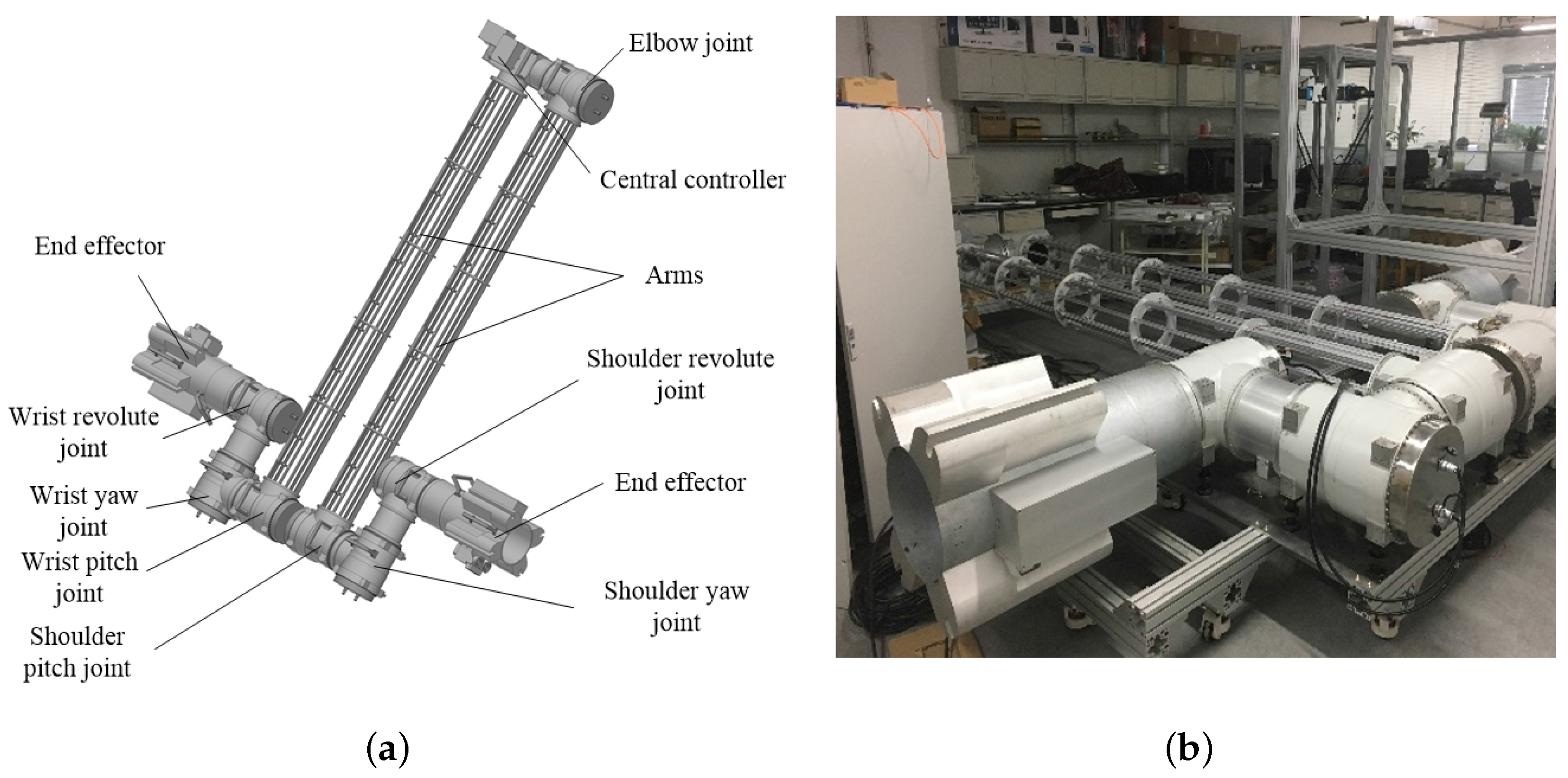
2.1. Introduction of Simulated Manipulator
The simulated manipulator, shown in Figure 1, is designed according to an actual space manipulator. The manipulator contains seven sets of interchangeable revolute joints, two end effectors, two arms, and one central controller. They are distributed symmetrically. The manipulator has seven rotary DOF. When it operates, one end effector is fixed on the astrovehicle, and the other one can capture the target.
Figure 1.
Structure of the simulated manipulator: (a) computer model; (b) mock-up.
In order to reduce the manufacturing cost, the simulated manipulator is completely redesigned. The materials and the structure of it are quite different from the space one. To guarantee the equivalence between the simulated manipulator and the actual space manipulator, the simulated manipulator need to satisfy the indices shown in Table 1, while the joints are the most important components of the manipulator. Therefore, the parameters of them are a focus in this study.
Table 1.
Indices of the simulated manipulator.
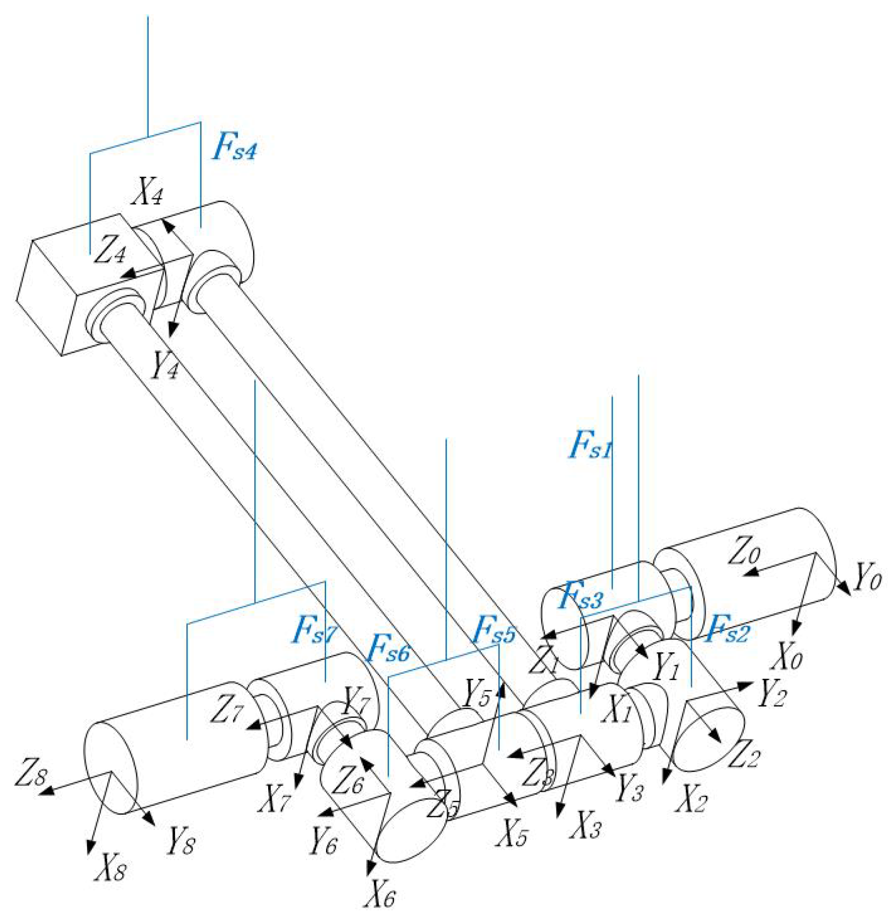
2.2. Kinematics of Manipulator
This serial manipulator, shown in Figure 2, consists of a base link (link 0) and seven links connected in series by seven rotation joints without forming a closed loop. Each joint is controlled by an actuator.
Figure 2.
Manipulator and coordinate systems.
To describe the geometry of the manipulator, starting from the basic link, we number the links sequentially from 0 to 7 and the joints from 1 to 7. Following the Denavit–Hartenberg (D–H) convention, a Cartesian coordinate system is established and the D–H rotation matrices can be obtained
where the rotation matrices means from the th joint to the ith joint.
Each joint is attached to a sling in this suspension system. The extension line of each sling passes the barycenter of the corresponding joint. Ideally, the suspension force can balance the gravity. Then, the resulting force exerted on the joint is zero, and the manipulator is in a zero-gravity simulation environment.
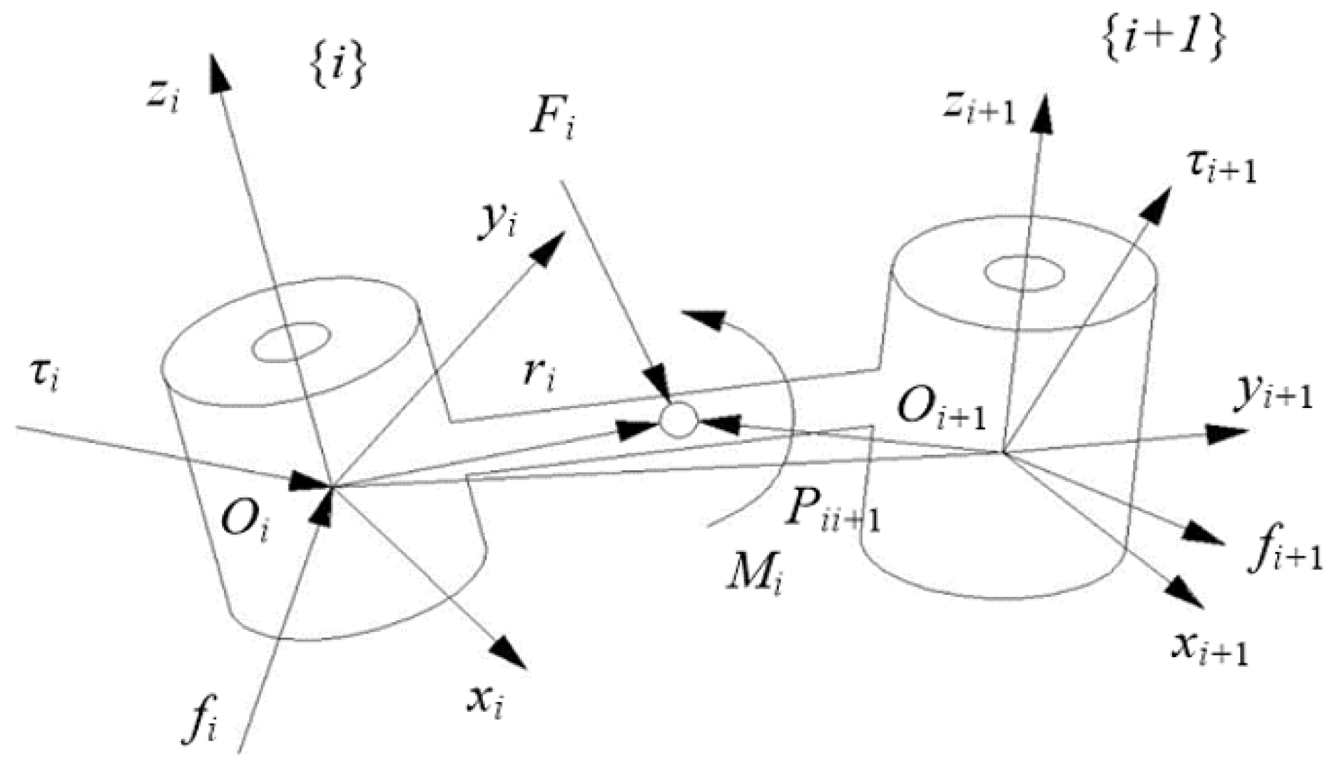
2.3. Dynamics of Manipulator
There are two types of dynamical problems: direct dynamics and inverse dynamics. The direct- dynamics problem is to find the response of a robot arm corresponding to applied torques and forces. That is, given a vector of joint torques or forces, we wish to compute the resulting motion of the manipulator as a function of time. The inverse-dynamics problem is to find the actuator torques and forces required to generate a desired trajectory of the manipulator.
The dynamical equations of motion can be formulated via several methods, such as the Newton–Euler laws, Lagrange method, Kane method, and Appell equations. The Newton–Euler laws is used to solve the dynamics problems in this study.
The link parameters are illustrated in Figure 3. Two adjacent links are i and , and the link reference coordinates are and . The angle, angular velocity, and angular acceleration of link i are , , and at the coordinate . To establish the expressions of dynamics, the following parameters, presented in Table 2, are employed. The subscript i means that the parameter expresses in the coordinate system of link i.
Figure 3.
Definitions of the link parameters.
Table 2.
Parameters used in dynamics.
The initial conditions for the basic link (link 0) are as follows:
and can be written as
and are obtained by differentiating and with respect to time
The recursion formula for the linear acceleration of the barycenter is computed as
The recursion formula of the inertia force and inertia torque are obtained
where is the mass of link and is the inertial matrix in the barycentric coordinate system.
The backward expressions are
when the manipulator operates in the active compensation suspension system, it is exerted by suspension forces and gravity. Ideally, the suspension forces can balance the gravity. However, there are some deviations in the magnitude, direction, and point of application of the suspension force, which cause the Inertia force and Inertia torque at barycenter of each joint.
Assume the mass of link i is and the suspension force is . The suspension force and the gravity of link i are transformed into the link i coordinate system as follows:
By substituting Equation (8) to Equation (7), the backward force and torque expressions can be established
Equation (9) can be used to calculate the force and torque of each joint of the manipulator.
3. Optimized Design of Mass-Matching of Joints
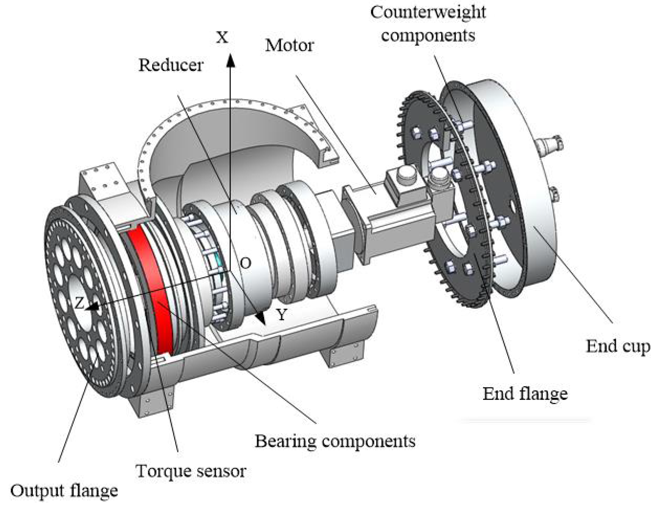
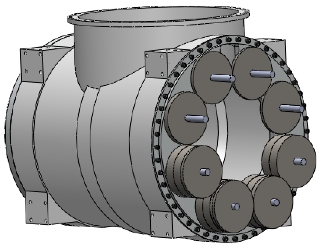
3.1. Modeling of Joints
The joint of the simulated manipulator is shown in Figure 4. It consists of a box, a servo motor and its components, and counterweight components. The thickness of the box is 10 mm, and its maximum diameter is 345 mm. The servo motor and its components consist of a motor, a reducer, a torque sensor, and connectors, which can achieve the motion control and torque measurement of the joint. The counterweight components are used to adjust the barycenter of the joint.
Figure 4.
Joint design of the simulated manipulator.
The fixed axis and the output axis of the joint are perpendicular. A joint coordinate {O-} is attached to the joint, whose y-axis overlaps the fixed axis, while the z-axis overlaps the output axis. Because of the mass index, shown in Table 1, the mass and barycenter of the simulated manipulator joint should be adjusted to match those of the actual space manipulator. Thus, the masses and barycenters of the counterweights need to satisfy
where , , and are the barycenter vector of the ith counterweight, the space manipulator joint, and the jth component (except counterweight components) in the joint coordinate system. In addition, , , and are the masses of them.
3.2. Optimization of Mass-Matching
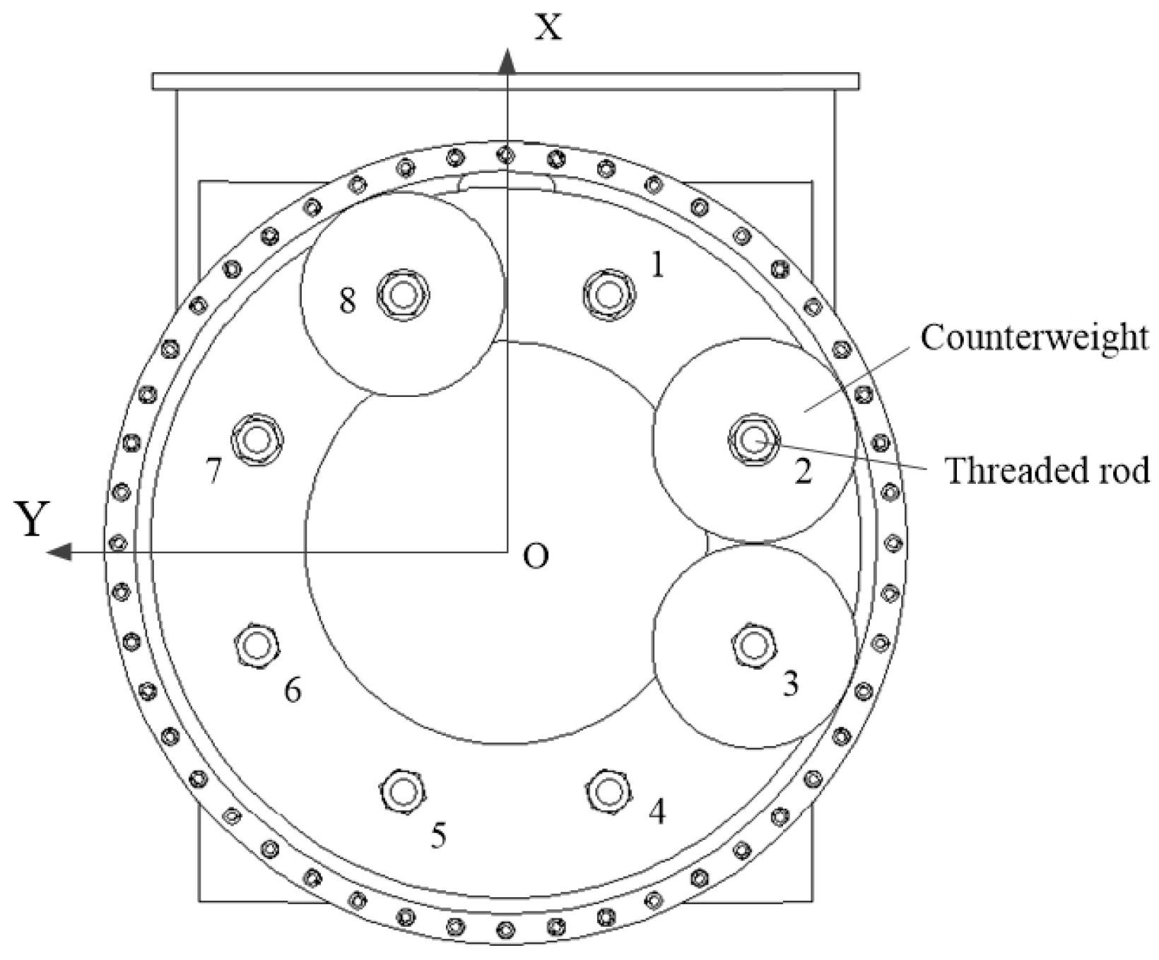
3.2.1. Design of Counterweight Components
The counterweight components consist of threaded rods and several cylindrical counterweights, shown in Figure 5. The eight threaded rods are uniformly distributed in a circle, numbered sequentially from 1 to 8 in clockwise order. The masses of the cylindrical counterweights are certain, at values including 1, 0.5, and 0.3 kg. The counterweights will be installed in the corresponding rods, to adjust the mass and barycenter parameters satisfying the index.
Figure 5.
Counterweight components of the simulated joints.
3.2.2. Optimization Method
In comparison to the barycenter, the mass is easy to match to a certain value. Therefore, the mass can be considered as a constant. According to the mass index, barycenter deviation <5 mm and gravity deviation <1%, the mass-matching problem can be simply described as: calculate the distribution of the counterweights to make the barycenter deviation be minimum. Because the adjustment of counterweight pointing along the z-axis is continuous, we consider the barycenter projected in the plane first. The mathematical expression is as follows:
where R is the radius of circular distribution of the rods. are the the masses of the counterweights, installed in the corresponding rods. and are the scalar projections of and onto the x-axis, while and are the scalar projections onto the y-axis.
3.2.3. Mass-Matching Results
The quadprog function in MATLAB (R2015b, MathWorks, Natick, MA, USA), which can solve quadratic programming problems, is used to optimize the mass-matching problem. We need to transform Function (11) to the specified form
where
By substituting Fuction (14) to the quadprog function, we can obtain the optimization result:
Considering the convenience of the counterweights machining, the masses of the counterweights are changed to
According to the optimization result, we obtain the distribution of the counterweights, shown in Table 3, and the computer model, shown in Figure 6.
Table 3.
Installation parameters of the counterweights.
Figure 6.
Computer model of the counterweights distribution.
The mass and barycenter of the simulated joint after mass-matching are shown in Table 4. It is similar to that of the space one. The optimization method is effective.
Table 4.
Mass parameters of the actual space and simulated manipulator joints.
3.3. Barycenter Affected by Mass Error
The simulated manipulator includes seven identical joints, all of which must be optimized and corrected in their mass and barycenter. Because the boxes of the joints are cast. There are differences in the mass and barycenter, as shown in Table 5. The other components are machined or standard parts, so we can consider that they have the same masses.
Table 5.
Mass of the boxes of the joints.
The correction strategy is as follows. We use the joint with the lightest box as a standard for designing the counterweight, and the others have the same design. Then, according to the standard, we mill the counterweights of the others to the target mass in order to guarantee an identical mass. Using this strategy, the total masses of seven joints are same, while the barycenters have deviations.
The mass of the standard box is , and the barycenter is ; the total mass after the mass-matching is , and the barycenter is ; the mass of the counterweight of the standard box is , and the barycenter is . The mass of the joint k that needs to be corrected is . The boxes are homogeneous. The barycenter of the joint after correction can be obtained:
3.4. Inertia Matrix of Joint Affected by Counterweight
The counterweights will change the inertia of the joints, which will cause the additional torque. The inertia matrix of one cylindrical counterweight in the joint coordinate is derived in this section. We assume that the parameters of the counterweight are as follows: the radius , thickness , density , and barycenter position in joint coordinate system . The inertia matrix of the counterweight in its own coordinate system is
where
According to the parallel-axis theorem, the inertia matrix of the counterweight in joint coordinate is obtained:
where
4. Simulation Study
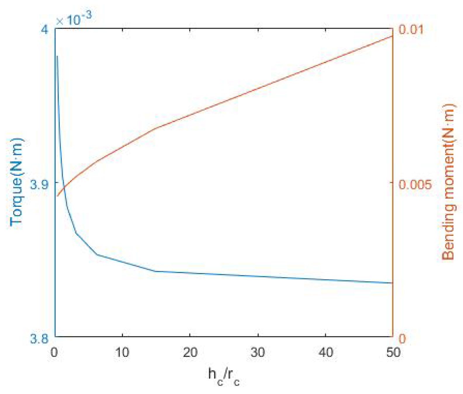
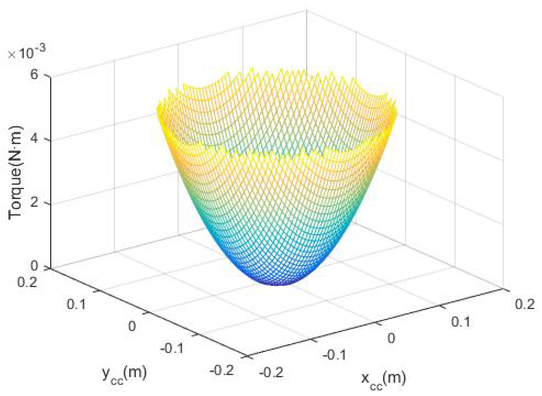
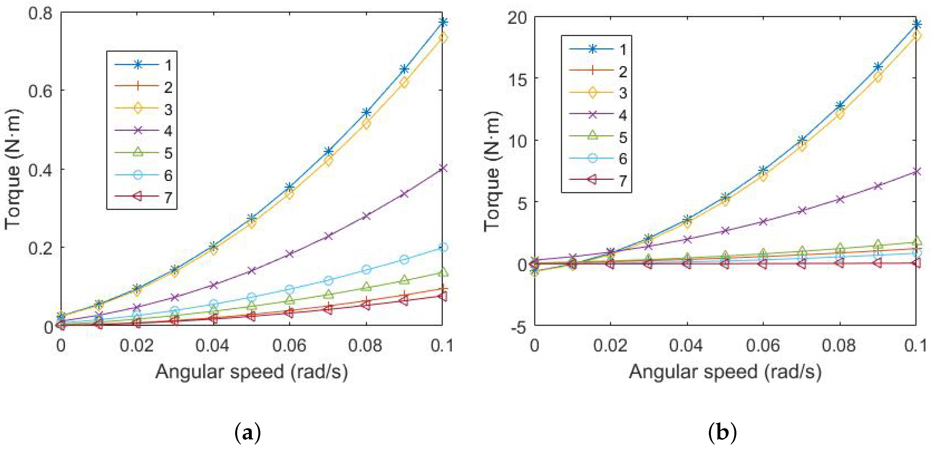
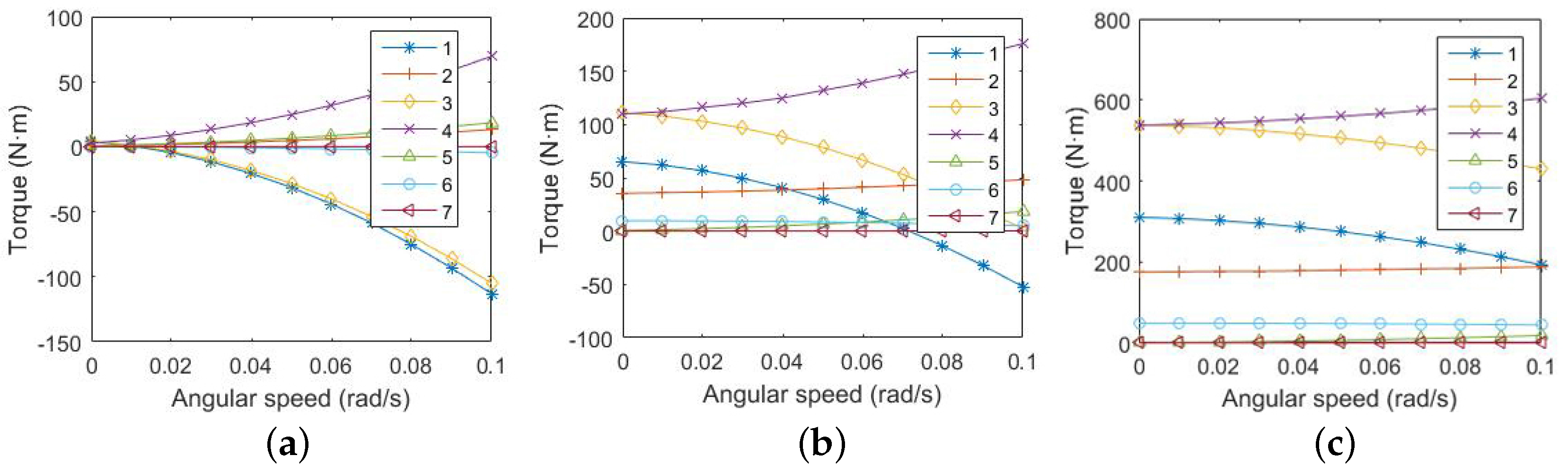
4.1. Torque of Joint Affected by Counterweight
Assuming the original parameters m, m, kg/m, and , , , , we use the control variate method to determine the effects of the counterweight parameters on the joint torque. Assume that the angular acceleration of the joint is 0.1 , the seven joints are identical, and the compensation suspension system can completely balance gravity.
When the counterweight have a constant mass, the additional inertia torque of the joint, affected by the changes of the size parameters and , is shown in Figure 7. The larger is, the smaller the torque is. However, the bending moment of the joint will be huge as the growth of . The joint torque and bending moment, and the installation possibilities of the sizes need to be considered when we choose the parameters of the counterweight.
Figure 7.
Joint torque and bending moment affected by and .
The additional inertia torque of the joint, affected by changes of the position parameters and , is shown in Figure 8. When the counterweight near the barycenter of the joint, the joint torque is small, but it is easy to cause interferences. The joint torque and the interference situation need to be considered when we choose the installation position of the counterweight.
Figure 8.
Joint torque affected by and .
When the counterweight is installed, the deviation of the position and mass of it is inevitable. This simulation result shows that a tiny error of the counterweight makes a little effect (about order of magnitude of N·m) on the joint torque. It indicates that the slight errors can be ignored.
4.2. Joint Torques of Simulated Manipulator
According to Section 2, the joint torques of simulated manipulator are calculated, shown in Figure 9. When the suspension force balance the gravity in magnitude and direction (Figure 9a), the torque comes from the deviation of the point of application, namely, the extension line of the suspension sling does not pass the barycenter. Joint 1 has the largest torque for it is the one closest to the base. With the increase of the suspension force error in magnitude, the torque is affected by both the deviation of the point of application and the unbalanced gravity, and it obviously increases. When the error is large (Figure 9c), the torques of joints 3 and 4 are the largest because of the long arms.
Figure 9.
Torque of the simulated manipulator joints: (a) the suspension forces balance the gravity in magnitude and direction; (b) has a suspension force error of 2%; (c) has a suspension force error of 10%.
4.3. Equivalence Analysis of Torque
After mass-matching, there are still some differences between the simulated and space joints, such as the small deviation in barycenter and the inertia. Figure 10 shows the torque deviation of them. After mass-matching, the difference between simulated and space joints is very small. It means that the experiments of simulated manipulator in the zero-gravity system is similar to the space one. We can predict the results of the space one by observing the simulated manipulator in the ground simulation experiments. However, the torque deviation without the counterweights, shown in Figure 10b, is about 25 times larger than that of the mass-matching one. It confirms that the mass-matching is effective and significant.
Figure 10.
Deviation of simulated and space joints: (a) deviation after mass-matching; (b) deviation without counterweight.
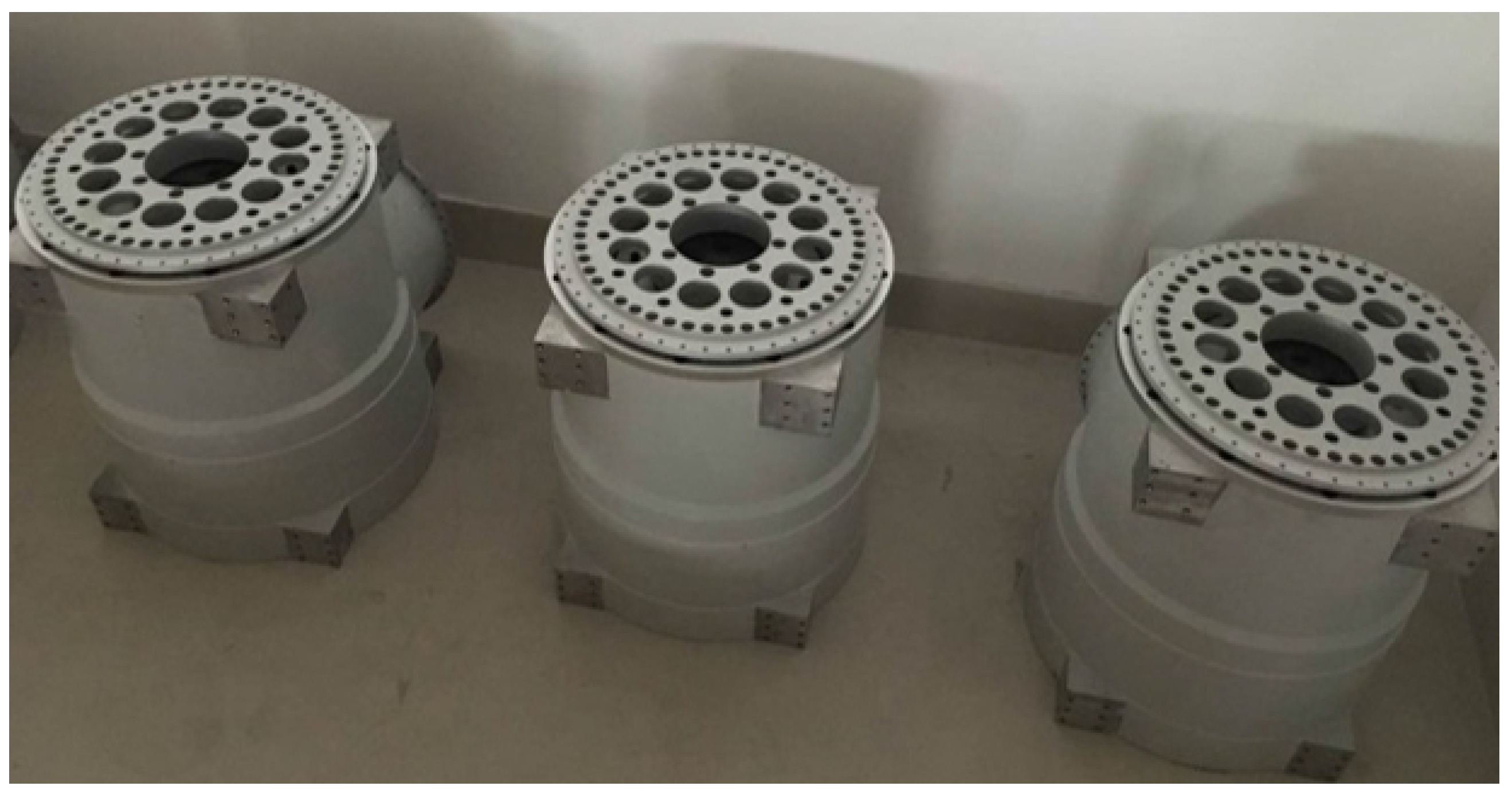
5. Experiment for Optimization Results of Mass-Matching
The mock-up of the joints of the simulated manipulator, shown in Figure 11, were manufactured and assembled. According to the optimization result of the mass equivalence in Section 3, the barycenter measurement testbed SZX-10 was used in an experiment, along with a Coordinate Measurement Machine (CMM). In the experiment, the CMM was fixed on the testbed, while the joint was fixed on the CMM. The barycenter of the joint in three directions was measured using a horizontal and inclination of 45 poses of the CMM. Table 6 shows the experiment results, which validate the equivalence analysis. The barycenter deviation was <5 mm, and the gravity deviation was <1%.
Figure 11.
Mock-up of joints after mass-matching.
Table 6.
Mass and barycenter of the joints.
6. Conclusions
In this study, counterweight components for matching the mass and barycenter of the joint of a simulated manipulator to those of an actual space manipulator is presented. Combined numerical derivation with computer programming, an optimization result of mass-matching, is achieved. The deviation of barycenter is <2 mm, which is greatly superior to the required indices. Then, the torque of each joint of the simulated manipulator in different suspension force error is calculated. With the increase of the force error, the torques increase fast, especially those of the 3rd and 4th joints. Furthermore, the torque deviations of simulated and space joints are calculated as well. The results show that the deviation is 25 times less after mass-matching. It confirms that the research is effective and significant. The results contribute to future experiments involving the actual space manipulator.
However, in this study, we consider the manipulator as a rigid object and ignore the elastic deformations and frictions. Actually, the slenderness ratio of two arms are large and the elastic deformations are obvious; when the manipulator operates, the frictions are existing between joints. To improve the accuracy of the model is part of our future work.
Acknowledgments
This research was supported by the National Natural Science Foundation of China (No. 91648107, 51475252) and by the Tsinghua University Initiative Scientific Research Program (No. 2014z22068).
Author Contributions
X.T. first conceived the idea; S.T. contributed analysis tools; C.X. analyzed the data; and S.T. wrote the paper.
Conflicts of Interest
The authors declare no conflict of interest.
References
- Yu, D.Y.; Sun, J.; Ma, X.R. Suggestion on Development of Chinese Space Manipulator Technology. Spacecr. Eng. 2007, 16, 1–8. [Google Scholar]
- Flores-Abad, A.; Ma, O.; Pham, K.; Ulrich, S. A review of space robotics technologies for on-orbit servicing. Prog. Aerosp. Sci. 2014, 68, 1–26. [Google Scholar] [CrossRef]
- Belser, V.; Breuninger, J.; Reilly, M.; Laufer, R.; Dropmann, M.; Herdrich, G.; Hyde, T.; Röser, H.-P.; Fasoulas, S. Aerodynamic and engineering design of a 1.5 s high quality microgravity drop tower facility. Acta Astronaut. 2016, 129, 335–344. [Google Scholar] [CrossRef]
- Dan, T.; Flight Global. Zero-G Flying Means High Stress for an Old A310. 2015. Available online: https://www.flightglobal.com/news/articles/zero-g-flying-means-high-stress-for-an-old-a310-410416/ (accessed on 23 March 2015).
- Carignan, C.R.; Akin, D.L. The reaction stabilization of on-orbit robots. Control Syst. IEEE 2000, 20, 19–33. [Google Scholar]
- Sato, N.; Wakabayashi, Y. JEMRMS design features and topics from testing. In Proceedings of the 6th International Symposium on Artificial Intelligence and Robotics & Automation in Space (I-SAIRAS), St-Hubert, QC, Canada, 18–22 June 2001. [Google Scholar]
- Brown, H.B.; Dolan, J.M. A Novel Gravity Compensation System for Space Robots. Available online: http://repository.cmu.edu/cgi/viewcontent.cgi?article=1216&context=robotics (accessed on 5 December 2017).
- Sato, Y.; Ejiri, A.; Iida, Y.; Kanda, S.; Maruyama, T.; Uchiyama, T.; Fujii, H. Micro-G emulation system using constant-tension suspension for a space manipulator. In Proceedings of the 1991 IEEE International Conference on Robotics and Automation, Sacramento, CA, USA, 9–11 April 1991. [Google Scholar]
- Liu, Z.; Gao, H.B.; Deng, Z.Q.; Tao, J.G. Gravity compensation for Rocker-bogie Rovers through single string tension. J. Mech. Eng. 2013, 49, 113–124. [Google Scholar] [CrossRef]
- Xiang, S.; Gao, H.; Liu, Z.; Yu, H.; Deng, Z. A novel active suspension gravity compensation system for physically simulating human walking in microgravity. IEEE Int. Conf. Robot. Biomim. 2017, 49, 1052–1057. [Google Scholar]
- Li, Y.Q.; Shao, Z.F.; Tian, S.H.; Tang, X.Q. Analysis and evaluation on unloading ratio of zero-g simulation device of space manipulator based on suspension system. Robot 2016, 38, 293–300. [Google Scholar]
- Kuroda, Y.; Teshima, T.; Satoc, Y.; Kubota, T. Mobility performance evaluation of planetary rover with similarity model experiment. IEEE Int. Conf. Robot. Autom. 2004, 2, 2098–2103. [Google Scholar]
- Yao, Y.S.; Mei, T. Simulation method of space operation on the ground–buoyancy method. Mech. Eng. 2008, 44, 182–188. [Google Scholar] [CrossRef]
- Hou, Y.M.; Ji, L.H.; Zhang, X.Y. Effect and mass-matching optimization of the dynamic balance on satellite attitude. Aerosp. Manuf. Technol. 2002, 3, 25–30. [Google Scholar]
- You, J.; Tian, Z.; Hou, X.Y. Genetic algorithm based optimization of counterweight distribution for reentry vehicle. Spacecr. Eng. 2015, 24, 56–61. [Google Scholar]
- Da Fonseca, I.M.; Goes, L.C.S.; Seito, N.; da Silva Duarte, M.K.; de Oliveir, É.J. Attitude dynamics and control of a spacecraft like a robotic manipulator when implementing on-orbit servicing. Acta Astronaut. 2017, 137, 490–497. [Google Scholar] [CrossRef]
- Alepuz, J.P.; Emami, M.R.; Pomares, J. Direct image-based visual servoing of free-floating space manipulators. Aerosp. Sci. Technol. 2016, 55, 1–9. [Google Scholar] [CrossRef]
- Masuya, K.; Sugihara, T. Com motion estimation of a biped robot based on kinodynamics and torque equilibrium. Adv. Robot. 2016, 10, 1–13. [Google Scholar] [CrossRef]
© 2017 by the authors. Licensee MDPI, Basel, Switzerland. This article is an open access article distributed under the terms and conditions of the Creative Commons Attribution (CC BY) license (http://creativecommons.org/licenses/by/4.0/).


