Article

Root Cause Identification of Machining Error Based on Statistical Process Control and Fault Diagnosis of Machine Tools

Key Laboratory of Education Ministry for Modern Design and Rotor-Bearing System, Xi’an Jiaotong University, Xi’an 710049, China
*
Author to whom correspondence should be addressed.
Machines 2017, 5(3), 20; https://doi.org/10.3390/machines5030020
Submission received: 3 April 2017 / Revised: 1 September 2017 / Accepted: 4 September 2017 / Published: 6 September 2017
(This article belongs to the Special Issue Advances in Process Machine Interactions)

Abstract

:
The essence of the machining process is the interaction that occurs between machine tools and a workpiece under certain conditions of cutting parameters. Root cause identification (RCI) is critical to the quality control and productivity improvement of machining processes. The geometric error caused by fixture faults can be identified in most RCI methods; however, the influence of machine tool degradation on workpiece quality is usually neglected. In this paper, a novel root cause identification scheme of machining error based on statistical process control and fault diagnosis of machine tools is proposed. With the pattern recognition of control charts, quality fluctuations can be detected in a timely manner. Once the machining error occurs, the fault diagnosis of machine tools are carried out. The relationship between machine tool condition and workpiece quality is established and the root cause identification of the machining error can be achieved. A case study of the machining of a complex welded box-type workpiece is presented to illustrate the feasibility of the proposed scheme. It is found that the coaxiality error of the two holes in two sides of the box’s wall is caused by the wear of the worm gear in the rotary work table of the machine tool.

1. Introduction

In order to maintain competition, manufacturing enterprises have to cope with growing demands for increasing product quality, greater product variability, and less cost. Quality control is a lasting topic in manufacturing engineering. In the past, quality in terms of geometric variation has been studied extensively. Many researchers have focused on modeling and controlling variation sources such as static deformation, kinematic error, thermal error, tool wear and vibration induced error. Statistical process control (SPC) is widely used in manufacturing processes for process monitoring and anomaly detection. SPC can sound the alarm for process anomalies; however, it cannot identify the root causes of the alarm. Thus, root cause identification (RCI) is critical to the quality control and productivity improvement of manufacturing processes.
The RCI methods in manufacturing processes can be divided into artificial intelligence (AI)-based methods and model-based methods. Artificial neural networks (ANNs) have been applied to improve data analysis and quality control in manufacturing processes [1]. It is well known that detecting the change point is an essential step in root cause identification, so some researchers have used ANNs to identify the change point at which the mean vector shifted [2,3]. Although ANN-based methods are efficient ways to detect the changes in the process mean vector, the root causes leading to these changes cannot be identified. In order to identify the root cause of process variations, process monitoring and diagnosis approaches based on Bayesian network [4], modified Bayesian classification [5], and dynamic Bayesian network [6] have been proposed. As for model-based methods, state space models are widely used, especially in multi-station manufacturing processes. A number of methodologies based on state space models have been presented for the diagnosis of fixture failures and dimension error in multistage manufacturing processes [7,8,9]. The state space models in the multistage manufacturing processes can characterize the propagation of fixture fault variation along the production stream. However, due to the presence of various uncertain factors in the manufacturing process, it is not enough to describe workpiece quality only in the geometrical dimensionality, and the causes of machining error are various and not limited to the fixture fault.
Fault diagnosis is an effective method for root cause identification. With the increase of service time, the performance of the machine tool degrades, such as spindle-bearing damage or the wear of guide and transmission components. The performance degradation of machine tools results in machining error and low-precision parts. To date, the condition monitoring of machining processes and machine tools has been studied widely to detect tool wear/breakage [10,11,12,13,14,15], spindle bearing damage [16,17,18], and chatter onset [19,20,21] effectively. However, there is still a gap between the fault diagnosis of machine tools and the root cause identification of machining error. On one hand, researchers in the field of machine condition monitoring (MCM) focused on running the state identification of machine tools and cutting processes; however, the influence of the machine tool state on the workpiece quality was usually neglected. On the other hand, investigations into root cause identification of machining errors were primarily conducted by varying the source transmission in a multistage manufacturing process. Through this method, the geometric errors caused by fixture faults can be identified, but other error sources induced by machine tool degradation are not considered.
In order to bridge the gap between the fault diagnosis of machine tools and the root cause identification of machining error, a novel scheme based on statistical process control and fault diagnosis of machine tools is proposed for the root cause identification of machining error. With the pattern recognition of control charts, the quality fluctuations can be detected in a timely fashion. Once the machining error occurs, the condition monitoring and fault diagnosis of machine tools are carried out to identify the root cause. An application case is used to demonstrate the feasibility of the proposed scheme.

2. The Root Cause Identification Method Based on Statistical Process Control and Fault Diagnosis

The essence of the machining process is the interaction process that occurs between the machine tool and the workpiece under certain cutting parameters. The input is the cutting parameters, such as cutting speed, feed speed, and depth of cut, while the output is the surface roughness, part dimension, and so on. The dynamic characteristics of the machine tool determine the machining accuracy. With the increase of service time, the performance of machine tools' main components degrades. Bearing damage and other faults in the transmission system may occur, which will eventually cause the reduction of machining accuracy. With the pattern recognition of control charts, quality fluctuations can be detected in a timely fashion. Meanwhile, the machine tool condition is monitored in real time with condition monitoring systems. The root cause identification of machining error can be achieved at the machine tool level by mapping the relationship between the machine tool state and the workpiece quality.
Figure 1 shows the scheme of root cause identification based on the statistical process control and fault diagnosis of machine tools.
The information of machine tool condition and workpiece quality is the foundation of the root cause identification of machining error. In order to obtain the full operational information of machine tools, a sensor network is used to collect the condition information via monitoring systems.
Due to the nonlinearity of machine tools in machining processes, the measured signals are usually non-stationary with noise. Advanced signal processing techniques are needed to extract features from the measured data. Through control charts and process capability analysis, the current fluctuations of quality can be monitored. If there are abnormal patterns, then abnormal process pattern recognition will be carried out, and the fault diagnosis of machine tools will be conducted to provide proofs for root cause identification.

3. Application

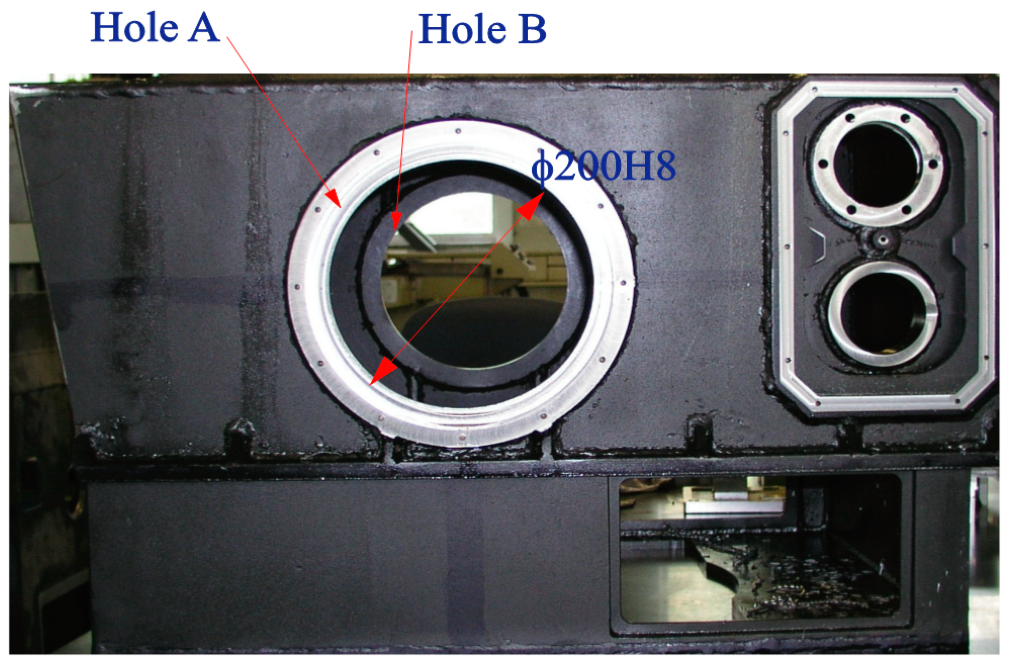
The proposed RCI scheme is open in concept, and can thus use different fault diagnosis methods according to various cases. In this paper, the scheme is applied to the machining process of a complex welded box-type workpiece, as shown in Figure 2. The box’s overall dimensions are large, with thin walls. The overall rigidity of the part is low, and many areas need to be processed. In addition, welding stress and compression deformation occur easily. In the machining process of several previous batches, the coaxiality (Φ0.01 mm) of two holes (hole A and hole B, Φ200H8) in the two sides of the box’s wall were unable to meet requirements. The method in this paper is used for the root cause identification of the coaxiality error.

3.1. Control Charts and Process Capability Analysis

The machining process of hole A and hole B is outlined as follows. Firstly, hole A was milled with the size of Φ200H8. Next, the rotary work table was rotated by 180°, and then hole B was milled with the size of Φ200H8. The detailed process steps are shown in Table 1.
Process capability analysis to ensure the coaxiality of hole A and hole B (Φ0.01 mm) was employed as follows. The quality information and the coaxiality of hole A and hole B were measured in the 24 groups. As shown in Table 2, the maximum of measurement value (Ma) is equal to 20 μm, and the minimum (Mi) is equal to 5 μm.
(1)
These 24 data are divided into six groups (i.e., K = 6) and there are four data in each group, then calculate the distance of each group:
h = M a M i K 1 = 20 5 6 1 = 3
(2)
Calculate the upper and lower boundary value of each group and determine the occurrence frequency and frequency density, as shown in Table 3. The distance between every two adjacent groups is h = 3.
(3)
Calculate the process capability index Cp and standard deviation σ.
The mean of the measured coaxiality is:
x ¯ = 1 n i = 1 n x i = 12.54   μ m
The standard deviation of the measured coaxiality is:
σ = 1 n i = 1 n ( x i x ¯ ) 2 = 4.69   μ m
The maximum of the measured coaxiality is:
T = 20   μ m
The process capability index is:
C p = T U T L 6 σ = ( 20 5 ) / ( 6 × 4.69 ) = 0.53
Since C p < 0.67 , the process capability is insufficient.
(4)
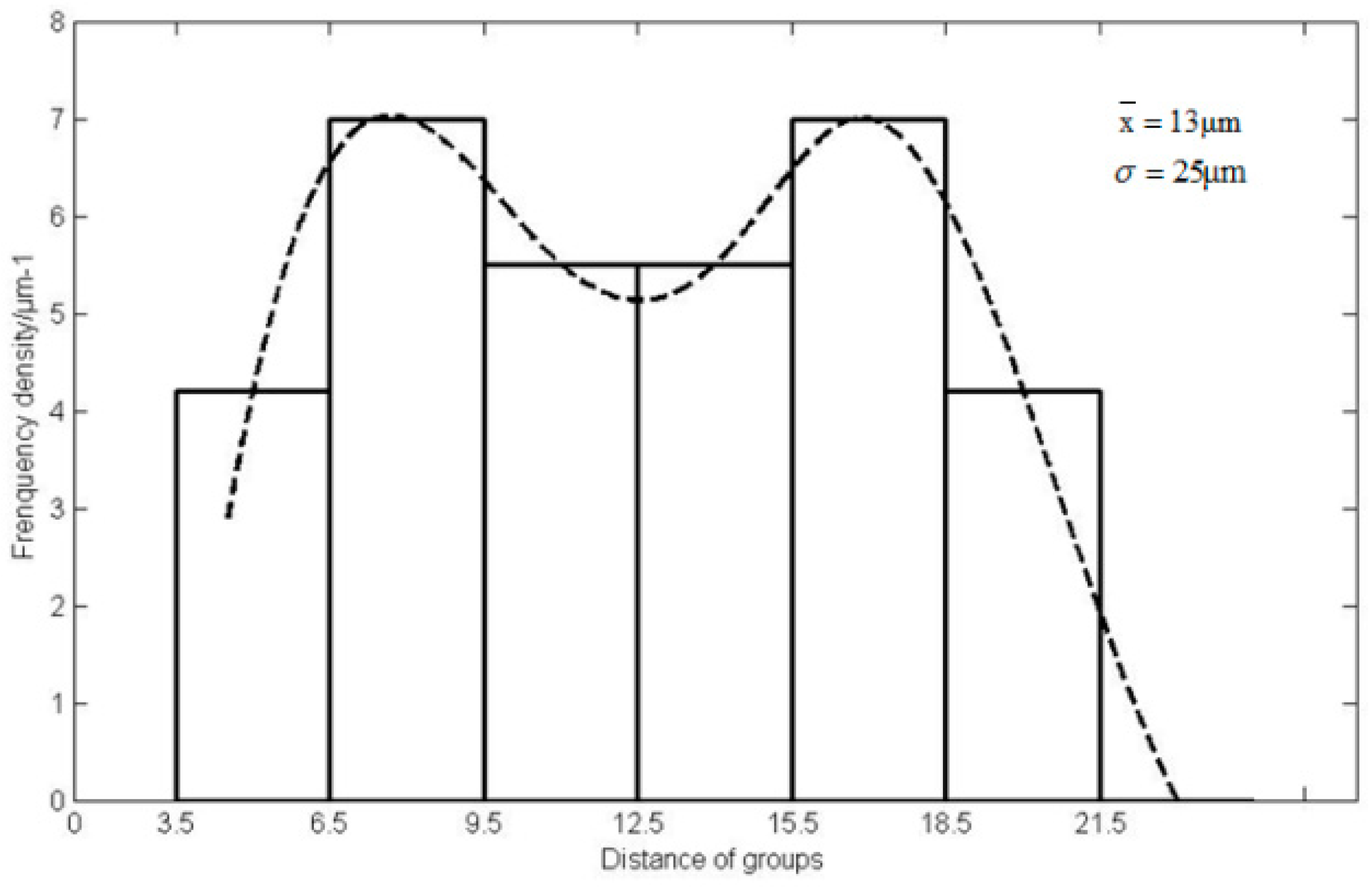
Draw the control distribution chart using frequency density as the ordinate and the distance of groups as the abscissa, as shown in Figure 3.
From the distribution chart (Figure 3), it can be seen that the dispersion range is wide and not centered, and the actual distribution chart is the bimodal curve with a superposition of two normal distribution curves. Therefore, random error may be mixed with the constant systematic error, such as the rotation error of the rotary work table, the clamping deformation of the workpiece, and the deviation from the cylindrical form of holes caused by the thermal deformation of tools.

3.2. Analysis of Root Cause

In an actual machining process, the root cause identification of machining error is a comprehensive problem, and the key is to identify the main error affecting the machining accuracy under specific conditions.
According to the analysis of the process capability and distribution chart, it can be derived that the main factors affecting the coaxiality error are the deformation caused by clamping force, the accumulated error from previous procedures, and cutting conditions.
In terms of the deformation caused by clamping force, the dial indicator was applied to support the plate and to observe that the reading on the dial indicator is within 0.01 mm. However, after the actual processing, the error still existed, so the deformation caused by clamping force can be excluded. As for the accumulation of process error, the accuracy in the last step was strictly controlled and the heat treatment was used to eliminate the generated stress. For the influence of cutting conditions, according to the working experience, a decrease in cutting depth and an appropriate increase in cutting speed are very useful to control the workpiece deformation; however, after several attempts, the coaxiality error still could not be eliminated.
Finally, we considered that the main cause of this coaxiality error was from the machine tool itself, and the preliminary judgement was that the error was caused by the performance degradation of the rotary work table.

3.3. Condition Monitoring and Fault Diagnosis of the Rotary Work Table

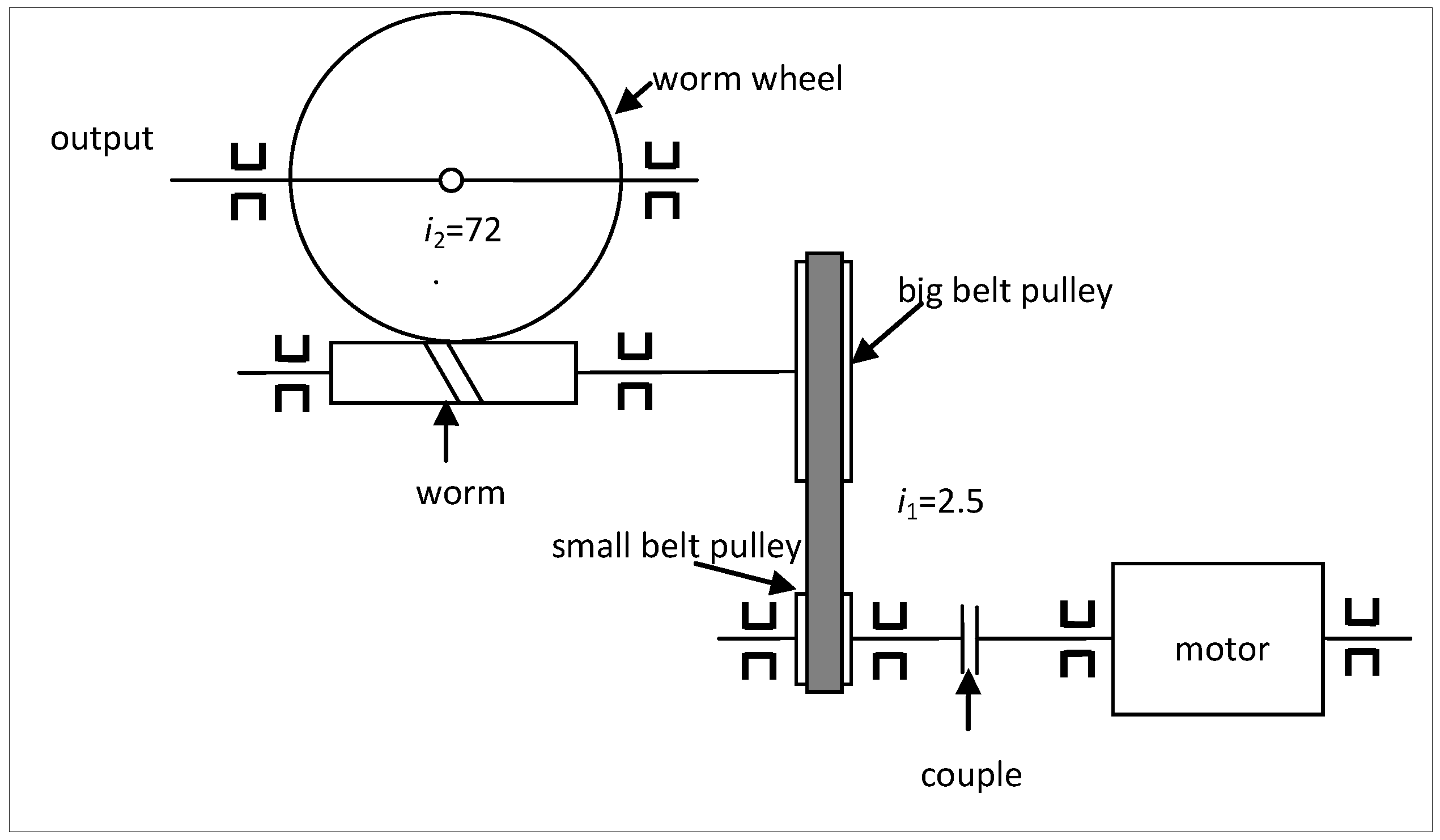
The drive system of the rotary work table is shown in Figure 4, which contains two levels of transmission. The transmission ratio of the belt drive and worm gear are 2.5 and 72, respectively. The worm gear drives the rotary work table. The number of threads of the worm Z1 = 1, and the number of teeth of the worm gear Z2 = 72. The accuracy of the rotary work table mainly depends on the accuracy of the worm gears. The main parameters are as follows:
(1)
The rotating frequency of the worm wheel: about 0.18 Hz
(2)
The rotating frequency of the worm: 13.2 Hz
(3)
The rotating frequency of the big pulley: 13.2 Hz
(4)
The rotating frequency of the small pulley: 33 Hz
(5)
The rotating frequency of the servo motor: 33 Hz
● Data acquisition
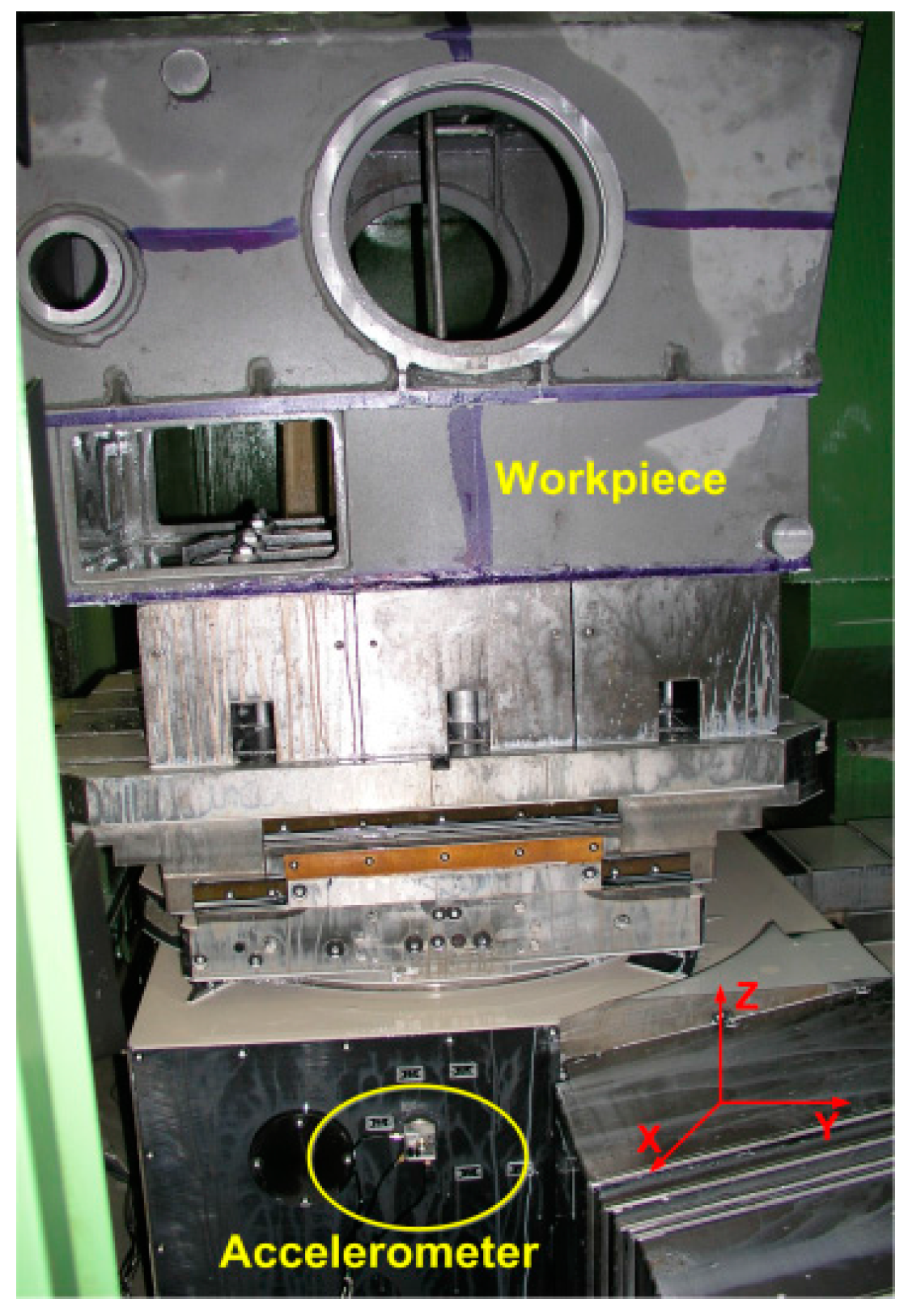
Vibration signals are easy to measure and widely used in condition monitoring systems. The three-dimensional piezoelectric accelerometer LC0110 was utilized to detect the vibration acceleration signals of the rotary work table during rotation (Figure 5). The sampling frequency was set as fs = 12.8 kHz.
● Signal processing and feature extraction
The vibration signal and its frequency spectrum in the X direction of the rotary work table are shown in Figure 6. There are three concentrated peaks at 858 Hz, 1524 Hz, and 1960 Hz. These frequencies are much higher than the rotating frequencies of the pulley and motor, and may be the resonant frequencies of the rotary work table’s structure.
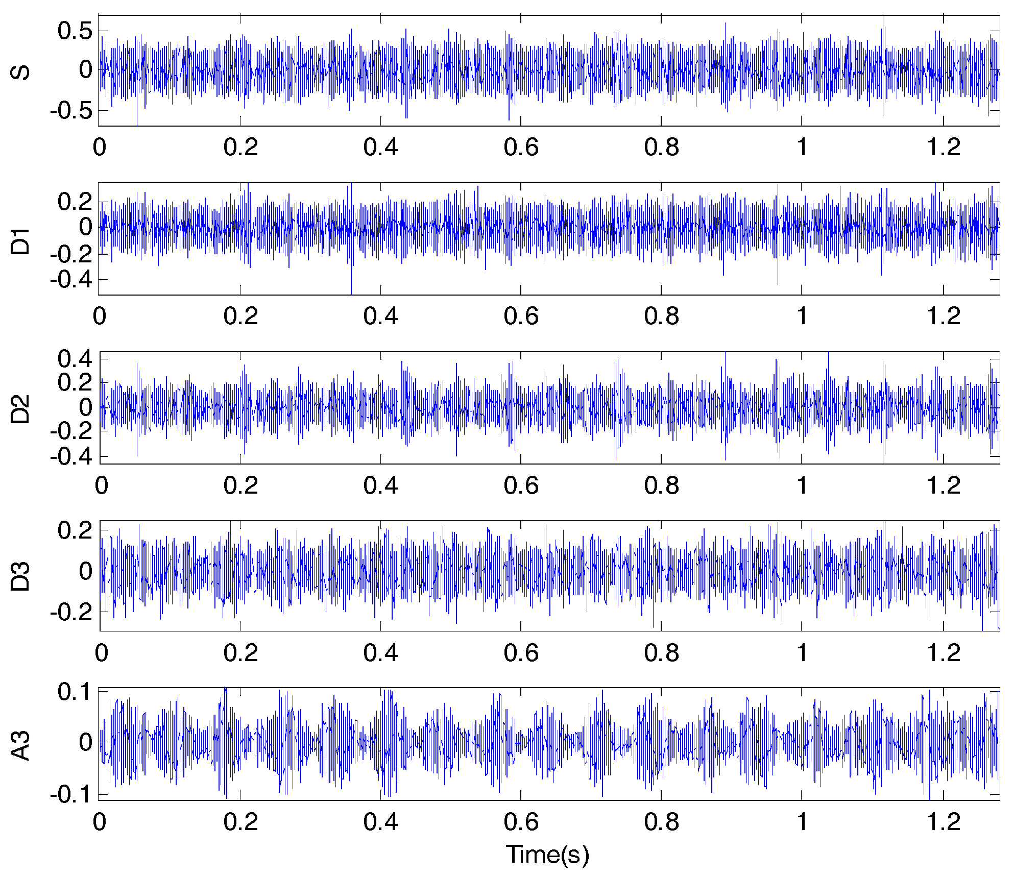
Wavelet transform is one of the most popular time-frequency-transformations, and can provide us with the frequency of the signals and the time associated to those frequencies, making it very convenient for its application in mechanical signal analysis. Applying wavelet decomposition of the original signal to three levels, the approximation signal A3 and three detailed signals D1, D2, and D3 are obtained and shown in Figure 7. Among them, A3 belongs to the frequency band 0~0.8 kHz, and the frequency band widths of D3-D1 are 0.8~1.6 kHz, 1.6~3.2 kHz, and 3.2~6.4 kHz, respectively.
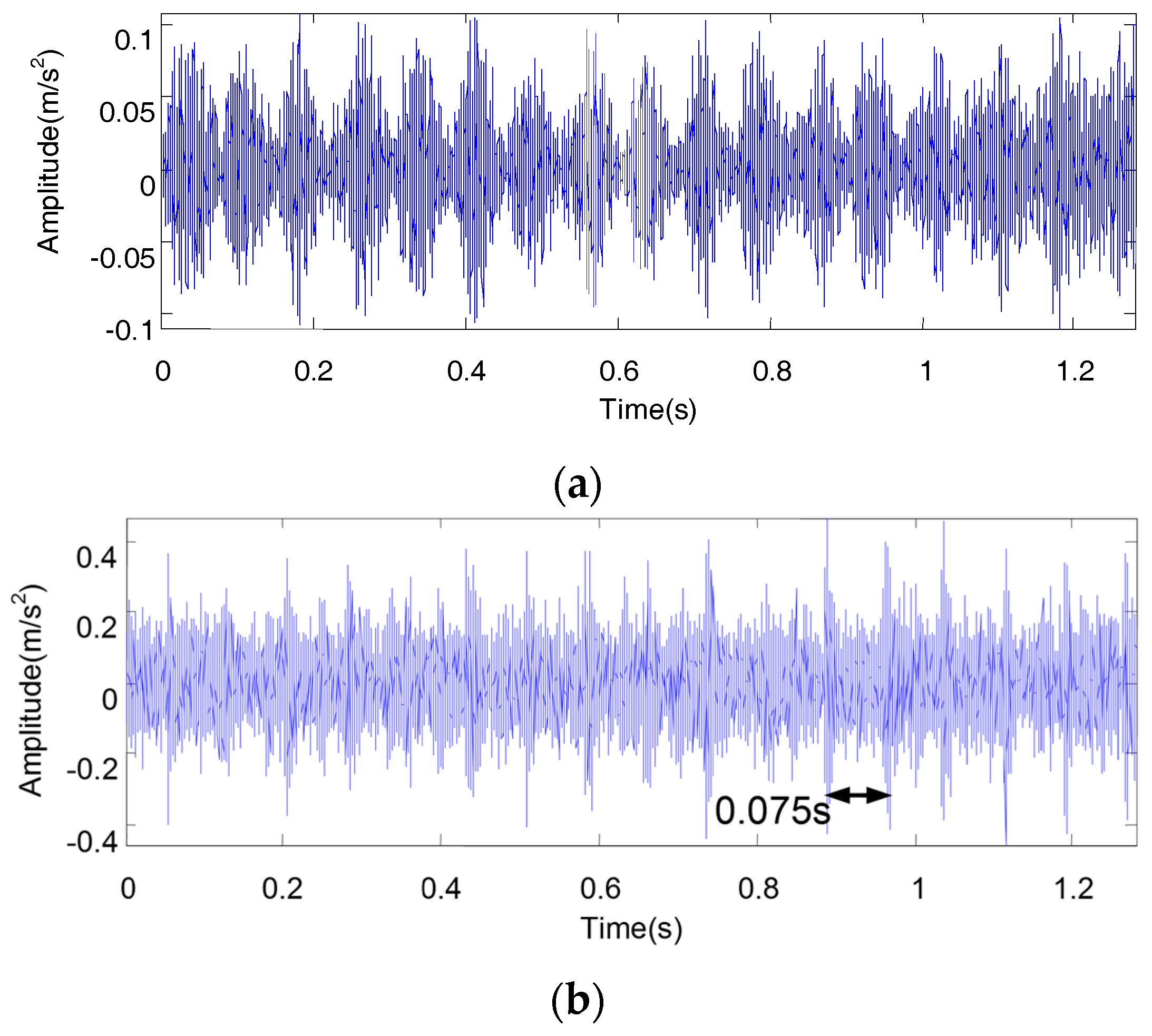
From Figure 7, it can be seen that there is the phenomena of amplitude modulation and impulse responses in the decomposed signal. In order to analyze these clearly, the approximation signal A3 and detailed signal D2 are shown in Figure 8, wherein we can find that a strong impulse appears once per revolution of the worm and that a regular amplitude modulation is induced. The phenomenon of amplitude modulation can be seen in Figure 8a, and there are 17 amplitude modulation waveforms. In Figure 8b, there are 17 distinct periodic impulses at equal intervals (0.075 s).
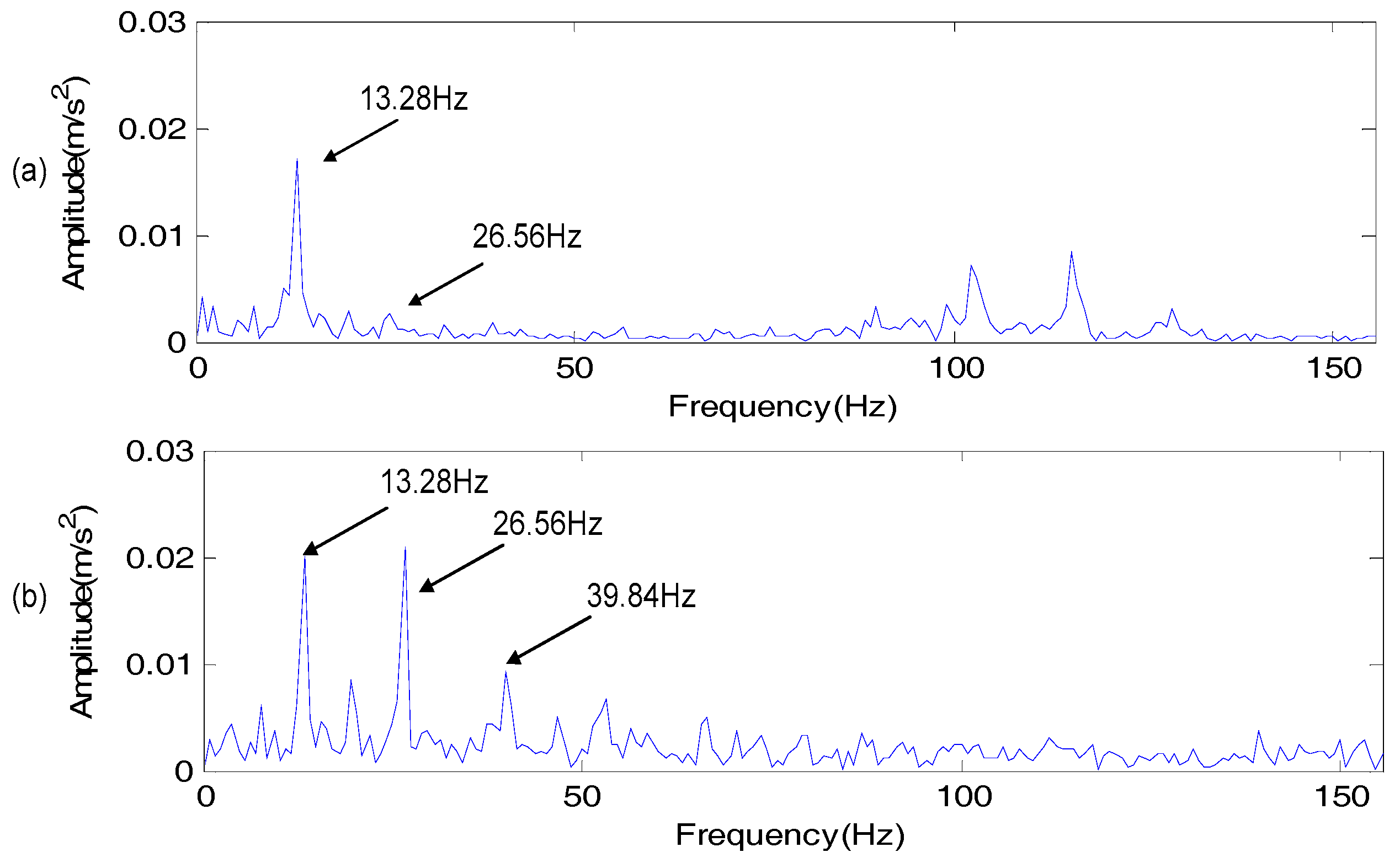
In order to further analyze the vibration signal, Hilbert envelope demodulation was applied to A3 and D2, respectively. The demodulation results are shown in Figure 9. The modulation frequency 13.28 Hz and its higher harmonics can be found from the envelope spectrum of A3 and D2. According to the demodulation results, we can confirm that the rotating frequency 13.28 Hz of the work table’s worm is the source of modulation, leading to strong vibrations of the work table and the decreased positioning accuracy. From the vibration signal processing, we can judge that serious wear of the worm and worm gear occurs.
● Identification of error sources
The transmission system is relatively simple. The vibration of the motor is greatly reduced through the soft belt and the motor frequency does not appear in the spectrum of the vibration signal. Thus, the motor is unlikely to affect the rotation accuracy of the output shaft.
In the wavelet analysis result of the vibration signal, it can be found that the main frequency components of its envelope demodulation spectrum are the worm’s rotation frequency and its harmonic frequencies. The vibration of the worm gear excites the natural frequency of the work table and causes the amplitude modulation phenomenon. In fact, failure modes of the worm gear are similar to those of the gear pair, such as wear, fatigue pitting, surface spalling of teeth, etc. Because the material of the worm gear teeth is usually softer than that of the worm and because the relative sliding at meshing is large, abrasive wear is prone to occur, and the failure always occurs on the worm gear. The wear of the worm and worm gear leads to the vibration increase of the rotary work table and a larger amplitude at the rotation frequency of the worm compared to the normal condition. An impulse is generated once per revolution when the worm and worm gear enter into the mesh area. Combined with the signal analysis results, the sever wear of the worm gear can be confirmed. Due to the wear of the worm gear, the clearance in the mesh area results in the decreased rotating accuracy of the rotary work table. Since other factors (e.g., clamping force, the accumulated error from previous procedures, and cutting conditions) affecting coaxiality error are excluded, the accuracy degradation of the rotary work table becomes the primary reason for the machining error.

4. Conclusions

In this work, a novel root cause identification scheme to identify machining error based on the combination of the statistical process control and fault diagnosis of machine tools was proposed. The SPC was used to detect fluctuations of the workpiece quality, while the fault diagnosis of machine tools was employed to identify failure parts that affect machining accuracy. The relationship between the machine tool condition and the workpiece quality was established to achieve deep root cause identification of the process error. The scheme was verified with the machining of a welded box-type workpiece as a case study. The results showed that the surface wear of the worm gear resulted in the decreased precision of the rotary work table and subsequently the coaxiality error of the two holes in two sides of the box’s wall. In future work, the online vibration measurements and coaxiality measurement during machining will be carried out in order to elucidate the relationship between the coaxiality and vibration.

Acknowledgments

This work was supported by National Natural Science Foundation of China (No. 51575423 and 51421004), and the Fundamental Research Funds for the Central University.

Author Contributions

H.C. conceived the original idea of root cause identification, finished the experimental validation, and analyzed the data. D.L. and Y.Y. wrote and edited the paper.

Conflicts of Interest

The authors declare no conflict of interests.

References

  1. Du, S.C.; Lv, J.; Xi, L.F. A robust approach for root causes identification in machining processes using hybrid learning algorithm and engineering knowledge. J. Intell. Manuf. 2012, 23, 1833–1847. [Google Scholar] [CrossRef]
  2. Atashgar, K.; Noorossana, R. An integrating approach to root cause analysis of a bivariate mean vector with a linear trend disturbance. Int. J. Adv. Manuf. Technol. 2011, 52, 407–420. [Google Scholar] [CrossRef]
  3. Guh, R.-S. On-line identification and quantification of mean shifts in bivariate processes using a neural network-based approach. Qual. Reliab. Eng. Int. 2007, 23, 367–385. [Google Scholar] [CrossRef]
  4. Dey, S.; Stori, J.A. A bayesian network approach to root cause diagnosis of process variations. Int. J. Mach. Tools Manuf. 2005, 45, 75–91. [Google Scholar] [CrossRef]
  5. Liu, J.L.; Chen, D.S. Fault detection and identification using modified bayesian classification on pca subspace. Ind. Eng. Chem. Res. 2009, 48, 3059–3077. [Google Scholar] [CrossRef]
  6. Yu, J.; Rashid, M.M. A novel dynamic bayesian network-based networked process monitoring approach for fault detection, propagation identification, and root cause diagnosis. Aiche J. 2013, 59, 2348–2365. [Google Scholar] [CrossRef]
  7. Ding, Y.; Shi, J.J.; Ceglarek, D. Diagnosability analysis of multi-station manufacturing processes. J. Dyn. Syst. Meas. Control-Trans. Asme 2002, 124, 1–13. [Google Scholar] [CrossRef]
  8. Djurdjanovic, D.; Ni, J. Dimensional errors of fixtures, locating and measurement datum features in the stream of variation modeling in machining. J. Manuf. Sci. Eng. 2003, 125, 716–730. [Google Scholar] [CrossRef]
  9. Zhang, F.P.; Lu, J.P.; Tang, S.Y.; Sun, H.F.; Jiao, L. Locating error considering dimensional errors modeling for multistation manufacturing system. Chin. J. Mech. Eng. 2010, 23, 765–773. [Google Scholar] [CrossRef]
  10. Grasso, M.; Colosimo, B.M.; Moroni, G. The Use of Adaptive pca-Based Condition Monitoring Methods in Machining Processes; American Society Mechanical Engineers: New York, NY, USA, 2012; pp. 133–140. [Google Scholar]
  11. Liu, H.Q.; Lian, L.N.; Li, B.; Mao, X.Y.; Yuan, S.B.; Peng, F.Y. An approach based on singular spectrum analysis and the mahalanobis distance for tool breakage detection. Proc. Inst. Mech. Eng. Part C-J. Eng. Mech. Eng. Sci. 2014, 228, 3505–3516. [Google Scholar] [CrossRef]
  12. Ritou, M.; Garnier, S.; Furet, B.; Hascoet, J.Y. Angular approach combined to mechanical model for tool breakage detection by eddy current sensors. Mech. Syst. Signal Proc. 2014, 44, 211–220. [Google Scholar] [CrossRef] [Green Version]
  13. Azmi, A.I. Monitoring of tool wear using measured machining forces and neuro-fuzzy modelling approaches during machining of gfrp composites. Adv. Eng. Softw. 2015, 82, 53–64. [Google Scholar] [CrossRef]
  14. Nouni, M.; Fussell, B.K.; Ziniti, B.L.; Linder, E. Real-time tool wear monitoring in milling using a cutting condition independent method. Int. J. Mach. Tools Manuf. 2015, 89, 1–13. [Google Scholar]
  15. Cao, H.; Chen, X.; Zi, Y.; Ding, F.; Huaxin, C.; Jiyong, T.; Zhengjia, H. End milling tool breakage detection using lifting scheme and mahalanobis distance. Int. J. Mach. Tools Manuf. 2008, 48, 141–151. [Google Scholar] [CrossRef]
  16. Chen, X.; Li, B.; Cao, H.; He, Z. The condition monitoring and performance evaluating of digital manufacturing process. In Proceedings of the First International Conference Intelligent Robotics and Applications, Wuhan, China, 15–17 October 2008; pp. 593–603. [Google Scholar]
  17. Cao, H.R.; Li, B.; He, Z.J. Study on modeling of digital machining process and its condition monitoring & diagnosis method. In Precision Engineering and Non-Traditional Machining; Wang, J.H., Zhang, C.F., Jin, X., Zou, J.L., Eds.; Trans Tech Publications Ltd.: Stafa-Zurich, Switzerland, 2012; Volume 411, pp. 622–625. [Google Scholar]
  18. Law, L.-S.; Kim, J.H.; Liew, W.Y.H.; Lee, S.-K. An approach based on wavelet packet decomposition and hilbert–huang transform (wpd–hht) for spindle bearings condition monitoring. Mech. Syst. Signal Proc. 2012, 33, 197–211. [Google Scholar] [CrossRef]
  19. Cao, H.; Zhou, K.; Chen, X. Chatter identification in end milling process based on eemd and nonlinear dimensionless indicators. Int. J. Mach. Tools Manuf. 2015, 92, 52–59. [Google Scholar] [CrossRef]
  20. Cao, H.; Lei, Y.; He, Z. Chatter identification in end milling process using wavelet packets and hilbert–huang transform. Int. J. Mach. Tools Manuf. 2013, 69, 11–19. [Google Scholar] [CrossRef]
  21. Cao, H.; Zhang, X.; Chen, X. The concept and progress of intelligent spindles: A review. Int. J. Mach. Tools Manuf. 2017, 112, 21–52. [Google Scholar] [CrossRef]
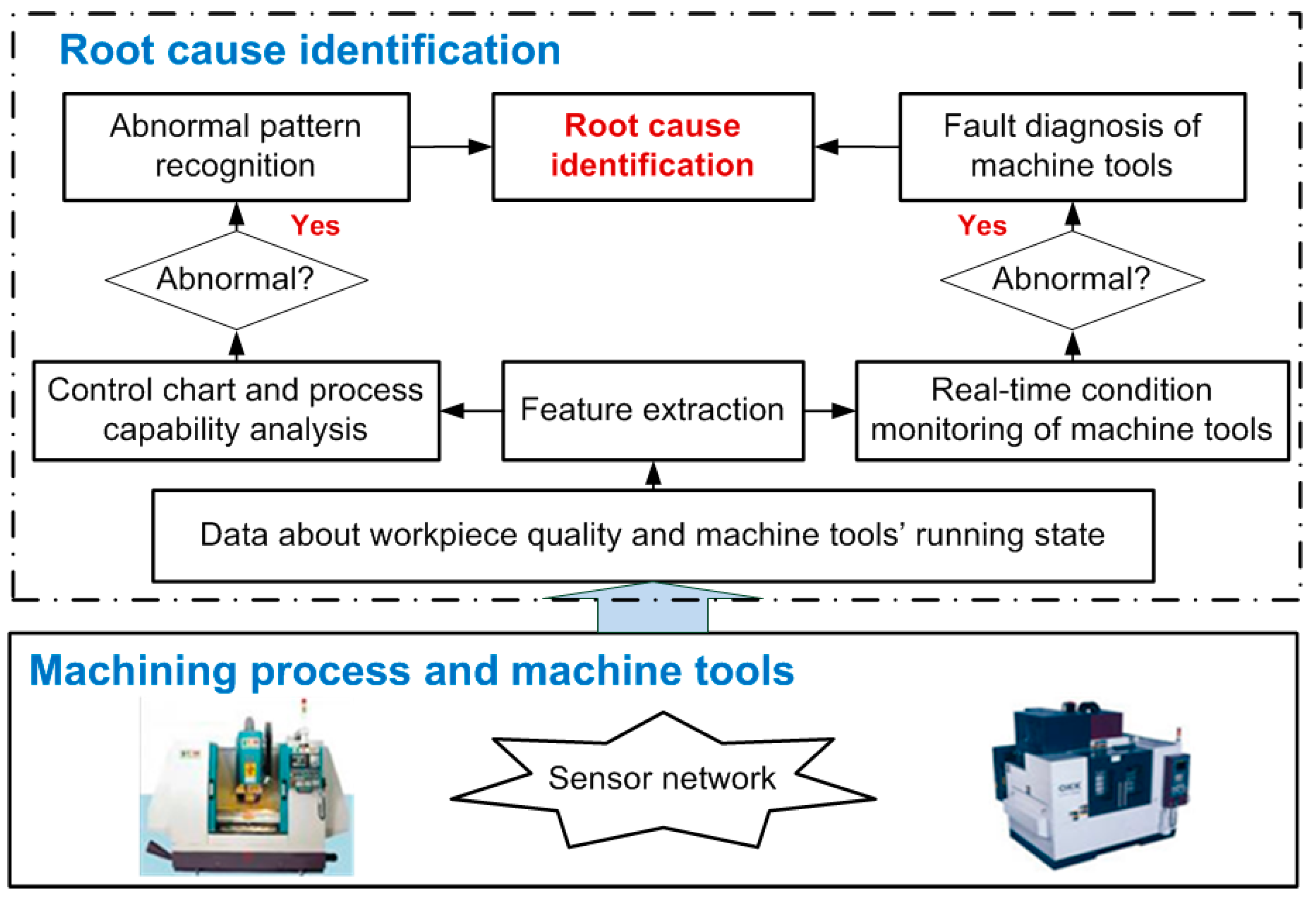
Figure 1. The scheme of root cause identification based on the statistical process control and fault diagnosis of machine tools.
Machines 05 00020 g001
Figure 2. The welded box-type workpiece.
Machines 05 00020 g002
Figure 3. The distribution chart.
Machines 05 00020 g003
Figure 4. The drive system of the rotary work table.
Machines 05 00020 g004
Figure 5. The sensor installation.
Machines 05 00020 g005
Figure 6. (a) The vibration signal in the X direction of the rotary work table; (b) The frequency spectrum in the X direction of the rotary work table.
Machines 05 00020 g006
Figure 7. Three layers wavelet decomposition.
Machines 05 00020 g007
Figure 8. (a) Approximation signal A3; (b) Detailed signal D2.
Machines 05 00020 g008
Figure 9. The envelope spectrum: (a) approximation signal A3; (b) detailed signal D2.
Machines 05 00020 g009
Table 1. The key process stages in the machining process.
SequenceProcess StepsQuality Requirements
1Mill a hole with the size of Φ198H10Unilateral allowance is 1 mm
2Rotate the work table with 180° and mill a hole with the size of Φ198H10Coaxiality ≤ Φ0.03 mm
3Annealing and release internal stress
4Mill a hole with the size of Φ200H8Cylindricity ≤ 0.01 mm
5Rotate the work table with 180° and mill a hole with the size of Φ200H8Coaxiality ≤ Φ0.01 mm
Table 2. The measurement of the coaxiality of hole A and hole B.
Sequence of WorkpieceCoaxiality/μmSequence of WorkpieceCoaxiality/μm
151313
2151412
3161513
417169
571710
651811
720198
819206
9182113
1020229
11112317
1292418
Table 3. The distribution of occurrence frequency.
Group NumberGroup Limit/μmCentral Value/μmFrequencyFrequency/%Frequency Density/μm−1
13.5~6.55312.54.2
26.5~9.58520.87
39.5~12.511416.65.5
412.5~15.514416.65.5
515.5~18.517520.87
618.5~21.520312.54.2