Article

Optimization Design and Performance Analysis of a PM Brushless Rotor Claw Pole Motor with FEM

School of Electrical Engineering, Beijing Jiaotong University, Beijing 100044, China
*
Author to whom correspondence should be addressed.
These authors contributed equally to this work.
Machines 2016, 4(3), 15; https://doi.org/10.3390/machines4030015
Submission received: 17 May 2016 / Revised: 14 June 2016 / Accepted: 1 July 2016 / Published: 7 July 2016

Abstract

:
A new type of permanent magnet (PM) brushless claw pole motor (CPM) with soft magnetic composite (SMC) core is designed and analyzed in this paper. The PMs are mounted on the claw pole surface, and the three-phase stator windings are fed by variable-frequency three-phase AC currents. The advantages of the proposed CPM are that the slip rings on the rotor are cast off and it can achieve the efficiency improvement and higher power density. The effects of the claw-pole structure parameters, the air-gap length, and the PM thinner parameter of the proposed CPM on the output torque are investigated by using three-dimensional time-stepping finite element method (3D TS-FEM). The optimal rotor structure of the proposed CPM is obtained by using the response surface methodology (RSM) and the particle swarm optimization (PSO) method and the comparison of full-load performances of the proposed CPM with different material cores (SMC and silicon steel) is analyzed.

1. Introduction

With the increasing environmental and fuel energy concerns, the focus on automotive electrification has dramatically increased in the last decade. The propulsion system of the vehicle has received much attention. Due to its high space usage, compact structure, low cost and excellent regulated performance, the CPM has been used for several decades as a vehicle alternator [1]. In order to improve the power density and the torque density of CPM, many unusual topologies have been presented and analyzed, such as the hybrid excitation CPM [2,3]. This kind of motor can prevent field leakage and increase the generator output capability, but it has electric brushes and a slip ring. This means that the manufacturing process and the maintenance cost will increase. In [4,5], the stator is a claw pole. The rotor is solid and the electric brushes and slip ring are cast off in this structure, but the leakage flux is larger. In [6], the stator and rotor are the claw-pole structure, and the ring PM is inset in stator yoke. Its power density is greatly improved, but the structure is quite complicated and not easy to manufacture. In [7], a brushless claw-pole double-rotor machine is proposed. The claw poles are separated from the stator and fixed on the outer rotor which is made of nonmagnetic and nonconductive material. PM segments are mounted on the inner magnetic rotor. The toroidal winding is enveloped by a U-shaped stator core. In [8], it has been found that the rotor-excited claw pole alternator exhibits a higher back-electromotive force production capability than the stator-excited claw pole alternator.
In recent years, the rapid development of powder metallurgy technique has provided a better way to make up for deficiencies such as the traditional manufacturing process of laminate being unfit for industrial manufacture of the claw pole machine with complex three-dimensional structure. The soft magnetic composites (SMC) material also has a lot of advantages such as magnetic and thermal isotropy, lower eddy current losses, easy and cost effective manufacturing process. The SMC material has often been applied in electrical machines with complex flux path and structure [9,10,11].
In this paper, a PM brushless rotor CPM with SMC core has been put forward. Its rotor is a claw pole structure and the PMs are mounted on the rotor surface. The combination fixing PMs on the surface of claws can weaken the leakage field and enhance the field of air gap. In order to improve its torque density and power density, the 3D FEM model is built, and the effects of the claw-pole structure parameters, the air-gap length and the PM thickness parameter of the proposed CPM on its output torque are investigated. The rotor geometry parameters (the thickness of pole tip l1, the thickness of pole root l2) and the length of air gap l3 are optimally designed by using the response surface methodology (RSM) [12] and the particle swarm optimization (PSO) [13,14] method. This work has significant implications for the parameter optimization of CPM. Finally, the comparison of full-load performances of the proposed CPM with different material cores (SMC and silicon steel) is analyzed [15].

2. 3D FEM Model and Magnetic Circuit of the Proposed CPM

The performances of the proposed CPM are determined by the PM material properties and the geometric dimensions, such as the air gap size, pole and yoke thickness. In order to design a high-performance CPM, some FEM and optimal methods must be used to compute and analyze its performances. Since the structure of the proposed CPM is relatively complicated, the 3D time-stepping FEM transient nonlinear model of the proposed CPM with practical geometries of stator and rotor laminations is developed based on the 3D finite-element commercial software (Maxwell-3D) [16]. The flux distribution, electromotive force (EMF) waveforms, output torque and cogging torque of the proposed CPM have been investigated by using the 3D TS-FEM transient nonlinear model.
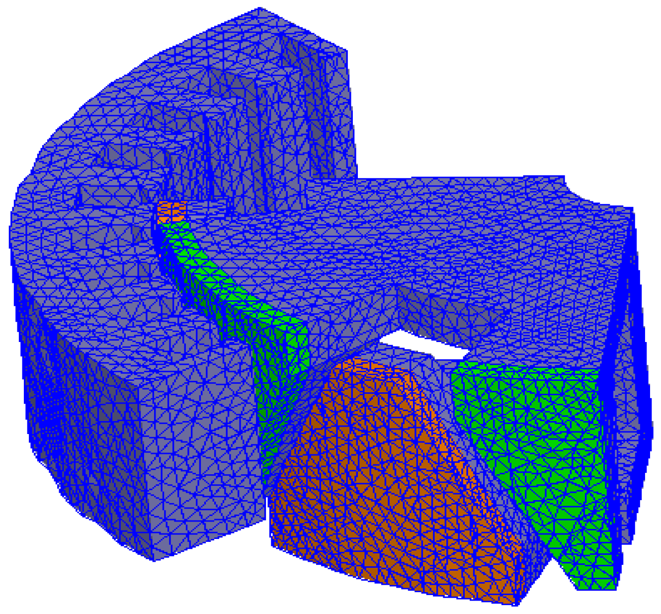
Figure 1 shows the 3D model of the proposed CPM. PM is placed on outer surface of the claw; therefore, the installation of the PM has to slot into the claw and sheath. The stator and claw pole cores are made up of SMC material. Finite element mesh plays an important role in 3D FEM analysis, and the mesh quality directly affects the precision of the simulation results. Taking into account the necessity of the accurate results and an acceptable computation time, the number of elements in the 3D FEM model of the proposed CPM is 580,284. During the full-load simulation of the proposed CPM, the simulation time is set to 0.04 s, and the simulation step is set to 0.001 s, the CPU time for the 3D-FEA equation solving is 1 h. Figure 2 shows a quarter of the 3D finite element mesh plot of the rotor and stator cores of the proposed brushless PM rotor CPM.
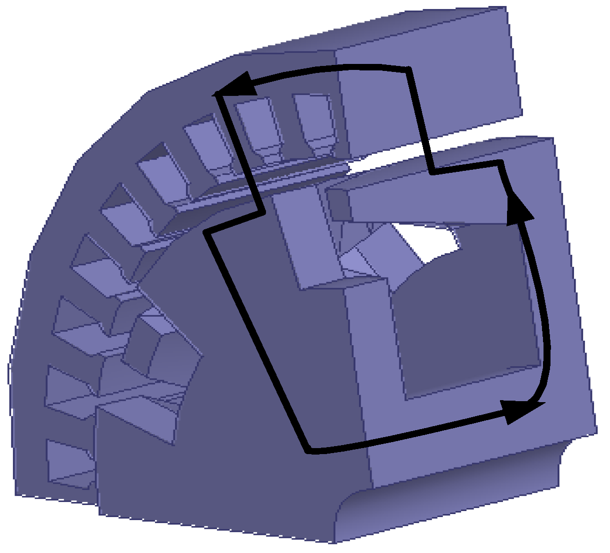
Figure 3 illustrates the 3D flux paths through the magnetic circuit of the motor. According to the 3D flux path, in Figure 3, we can distinguish the following major steps of the flux path:
  • axially in the magnetic core surrounding the shaft,
  • radially in the rotor north plate,
  • axially and radially in the rotor north claws,
  • radially in the air gap to the stator teeth,
  • circumferentially in the lamination following its subdivision into two paths,
  • radially down in the air gap through the stator teeth facing the two adjacent rotor south claws,
  • radially and axially in the two adjacent rotor south claws,
  • radially in the rotor south plate, and
  • axially in the magnetic core to close the loop.

3. Output Torque Investigation of the Proposed CPM

According to the developed 3D TS-FEM model of the proposed CPM, the performance of the proposed CPM can be computed. In order to improve its torque density, the geometry parameters of the proposed CPM should be redesigned by using some optimal methods. In this paper, the relationships among the variations of the thickness of pole tip (l1), the thickness of pole root (l2) and the length of air gap (l3) with the output torque are investigated and the three parameters are optimized.

3.1. The Impacts of the Pole Tip Thickness and the Pole Root Thickness

The size and shape of the claw pole not only affects the air-gap magnetic field and electromotive force waveform, they also affect the economy of the motor, so they must be carefully determined. Owing to the magnetic field lines in the pole tip part being relatively fewer than that in the claw root part, and considering the magnetic flux leakage between claw poles and the axial uneven distribution of air gap magnetic field, the claw pole magnetic flux will be more complex. So the rotor claw pole dimensions need reasonable and optimal selection, especially in terms of the thickness of the pole tip and root.
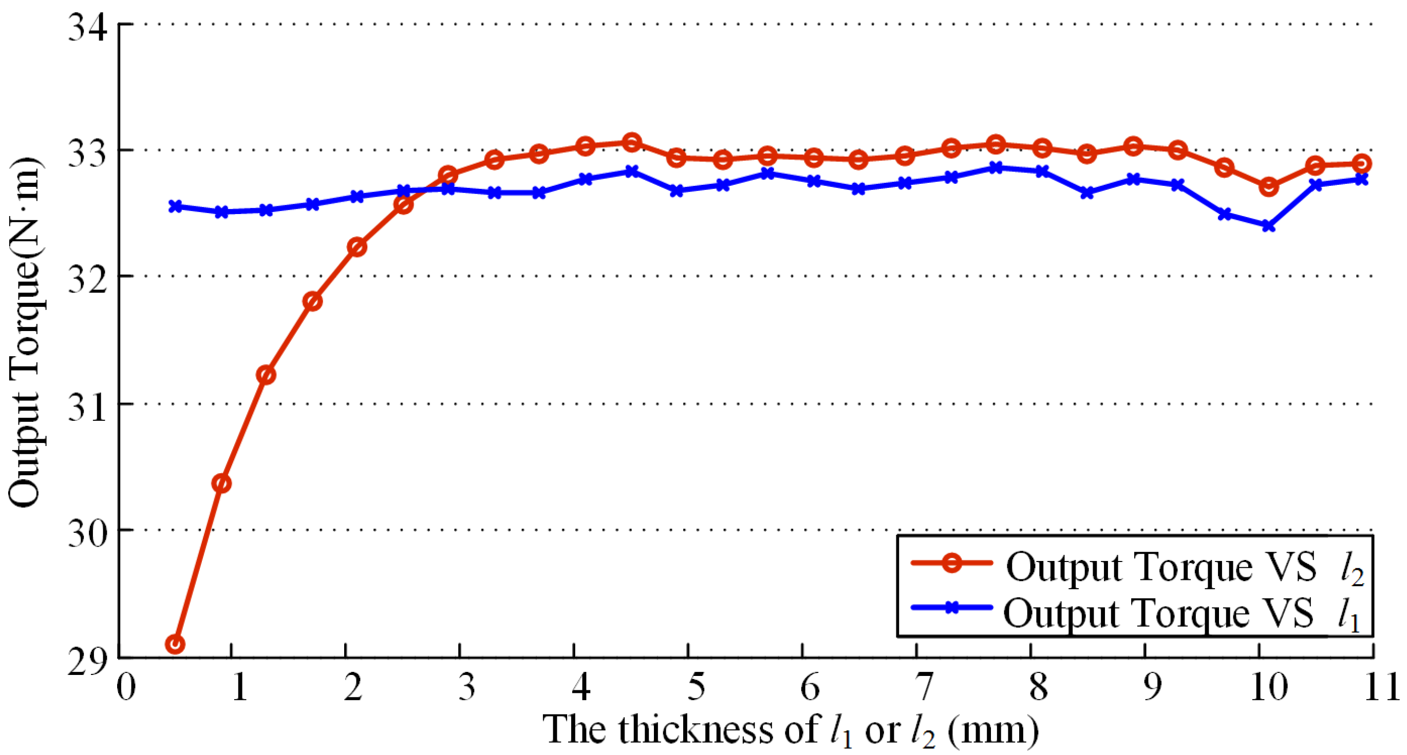
This part aims at changing the value of l1 from 0.5 mm to 11 mm when l2 keeps constant 11 mm and the value of l2 from 0.5 mm to 11 mm when l1 keeps constant 0.5 mm respectively, then analyzing the change of average output torque with various l1 or l2, and choosing the high average output torque on the premise of saving consumables and holding the toughness and strength of claw pole. So when the l1 and l2 changes respectively, the curves are shown respectively with different colors in Figure 4.
From Figure 4, we find that, when pole tip thickness l1 increases step by step, the average output torque remains about the same value (32.8 N·m). On the other hand, the average output torque remains nearly constant after increasing to a certain value (33 N·m) with the increase of pole root thickness l2.

3.2. The Impact of the Air Gap Length

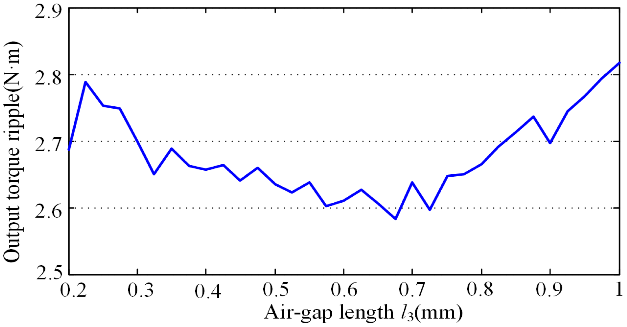
The air gap length (l3) can affect the output torque of the CPM. As a general rule, reducing the value of l3 is advantageous to improve the motor output torque during low speed running. However, with the increase of l3, the motor torque ripple value will decrease gradually, but when the l3 increases to a certain value, the torque ripple values will in turn increase.
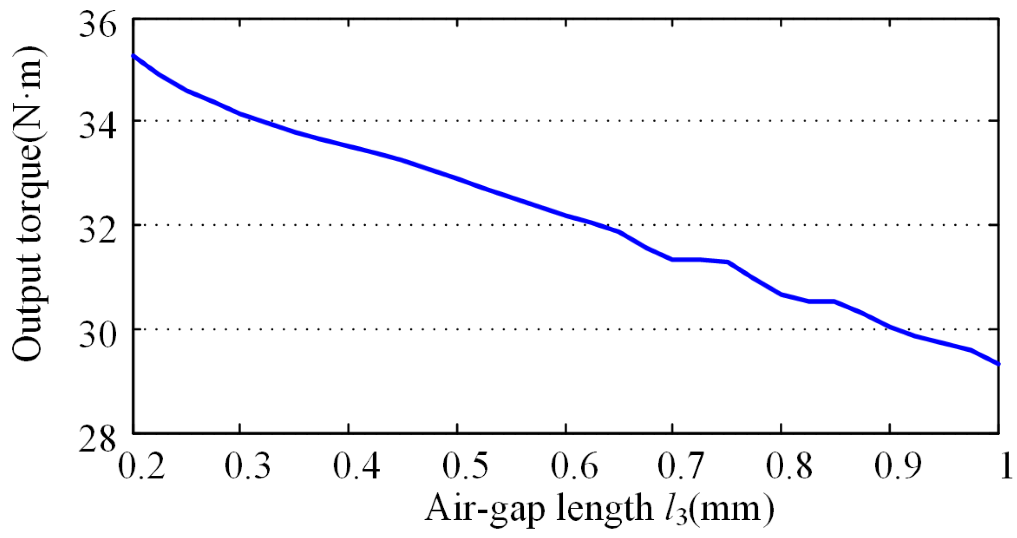
With the above analysis, we must consider the motor output torque and torque ripple at the same time, choose a suitable l3, and, as far as possible, achieve a large output torque with small torque ripple. Therefore, changing the value of l3 from 0.25 mm to 1 mm by 0.05 mm step, we get the curve of output torque ripple versus the thickness of air gap l3 in Figure 5 and the curve of output torque versus the l3 in Figure 6. The output torque ripple ∆T is defined as the half of the difference between the maximum output torque and the minimum output torque [17]. From the output torque ripple curve, we can find that when l3 increases in the range of 0 mm~1 mm, the torque ripple reduces at first and then increases. As is often true in the theoretical analysis, the output torque decreases with the increase of l3.

3.3. The Impact of the Thickness of Magnet

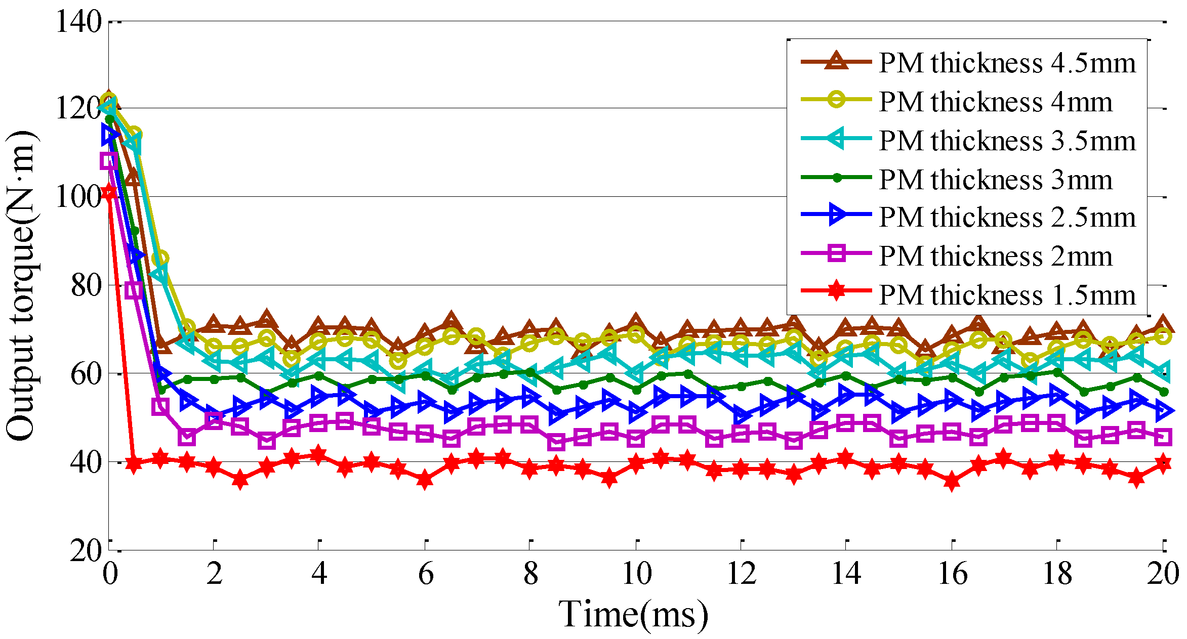
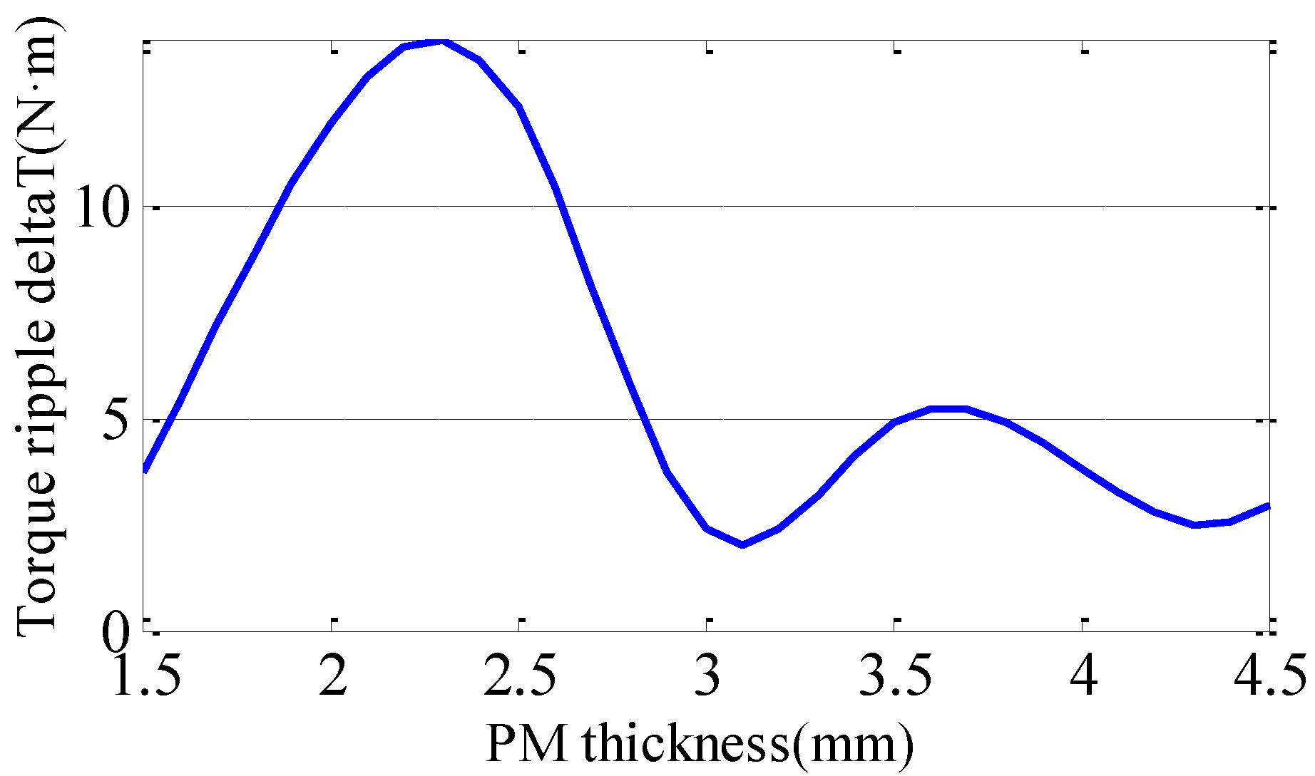
The flux field of the rotor is generated by the PMs fixed on the claw pole, so the PM thickness (l4) should be taken account under the condition of invariable air-gap and volume of the CPM. Therefore, in this paper, changing the thickness of PM from 1.5 mm to 4.5 mm with the 0.5 mm step, we get the output torque and the torque ripple ∆T versus the l4 in Figure 7 and Figure 8. Figure 7 is the curve of output torque with different l4 and Figure 8 is the curve of output torque ripple ∆T versus l4.
From Figure 7, it can be seen that, when l4 increases, the magnetic strength will be higher and the output torque will increase following the magnetic strength. The torque ripple is different. From the output torque ripple curve in Figure 8, we find that, when l4 increases in the range of 1.5 mm~4.5 mm, torque ripple reduces firstly and then increases and is minimum when it is near 3 mm.

4. Rotor Parameters Optimization of the CPM

Response surface methodology (RSM) is an interpolation technique that fits a multidimensional function to its function values at some sample points on an arbitrary function domain. PSO is a population based stochastic searching and optimization algorithm. Since the PSO method has the capability to search for the global optimum with high probability and its convergence rate is fast, it is advantageous to be combined with RSM in FEM to determine the optimized geometrical sizes of the proposed CPM.
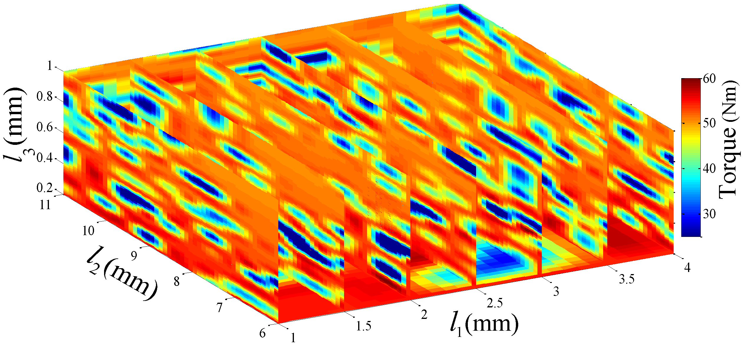
Figure 9 shows the slice contours of the output torque versus geometrical parameters (l1, l2, l3). From it, we find that, from the impact of geometrical parameters on the output torque, it is conductive to select the optimization method. The proposed optimal method is utilized to optimize the geometrical sizes of the proposed CPM, aiming to obtain a maximum output torque. A total of 1,309 sample points are computed using FEM, and approximation of the output torque T as a function of the geometry parameter (l1, l2, l3) is reconstructed by the RSM. The optimal solution is (3.5 mm, 7 mm, 0.2 mm), and the corresponding objective function value (output torque) is 56.54 N·m.

5. Performance Comparison of the Proposed Optimal CPM

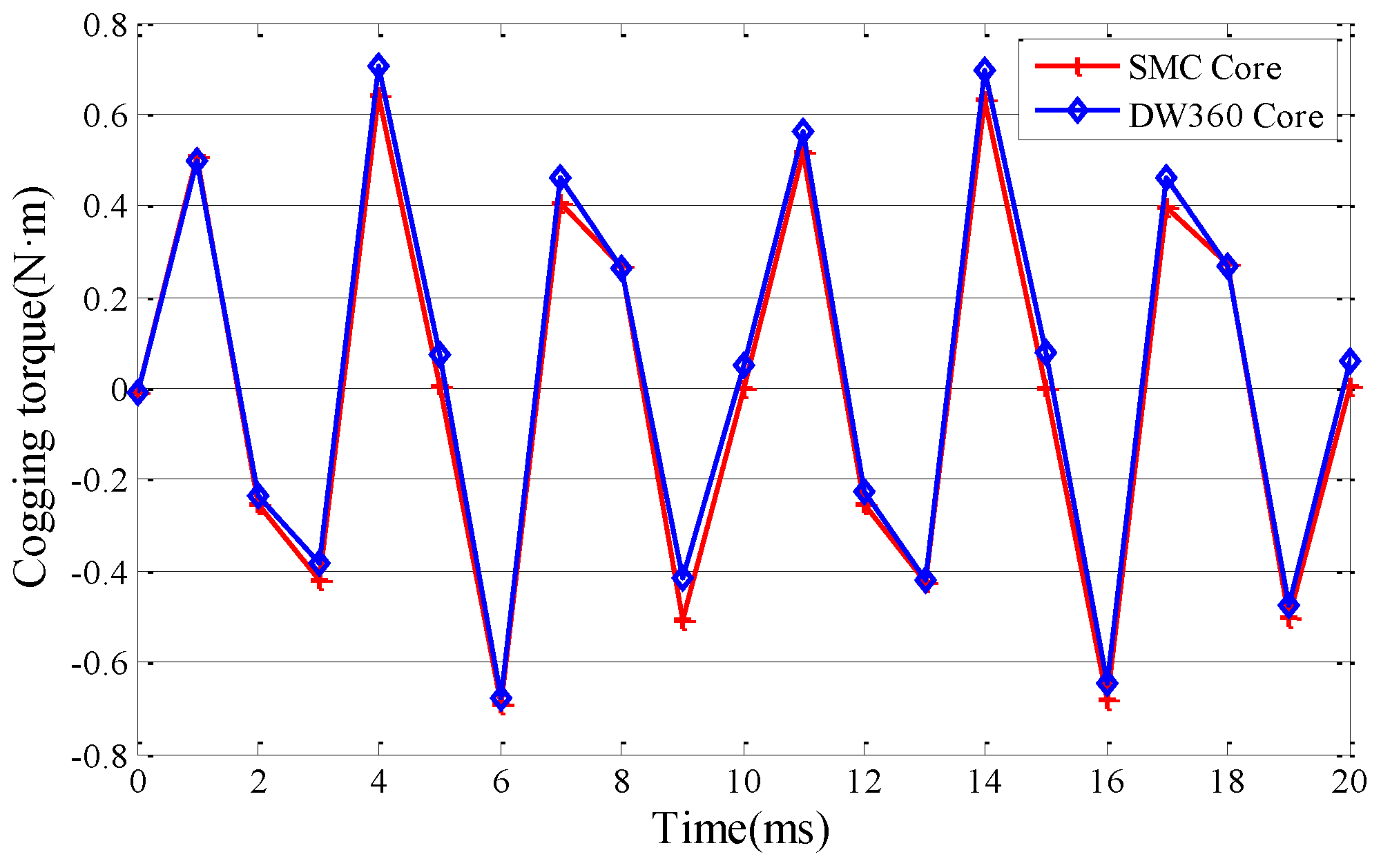
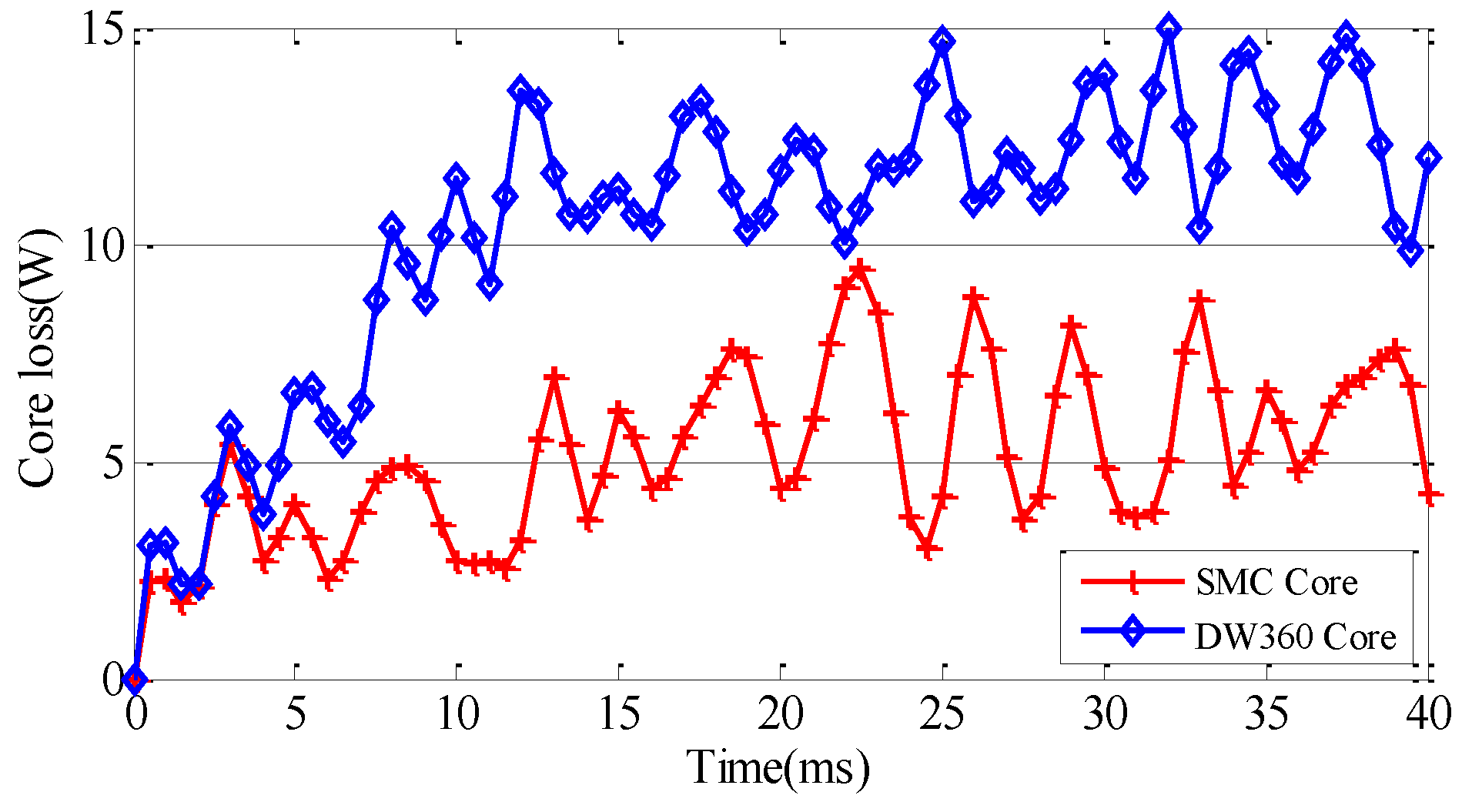
In what follows, special attention is paid to the variation of the output torque, the air gap flux density profile with respect rotor position, the cogging torque and the core loss of optimal CPM at full-load. The comparative analysis of cogging torque, and core loss with different core materials (DW360 core and SMC core) are shown.
Table 1 shows the essential parameters of CPM. Figure 10 shows that the average value of the air gap flux density is about 1.5 T, and the magnitude of the 6th operational harmonic of the CPM is 2.0 T and the magnitude of the 18th harmonic is 0.48 T. Figure 11 shows the torque comparison before and after parameters optimization of the proposed CPM. The cogging torque comparison in Figure 12 and core loss comparison with different cores in Figure 13 are presented. Obviously, by optimizing the parameters, the output torque has a 10 percent improvement and with the SMC material core, the core loss see a valid decrease, as shown in Figure 13. The core losses of the CPM with SMC core (6 W) are smaller than the losses associated with the DW360 core (12.5 W). From all the simulation results, the performances of the CPM and the property parameters of material (DW360, SMC) are summarized in Table 2. The output power of the optimization CPM is 2.96 kW and the efficiency is 98.92%.

6. Conclusions

In this paper, a PM brushless rotor CPM with SMC core has been presented and its 3D TS-FEM transient nonlinear model has been developed. The design method of the proposed CPM is studied concerning the construction of the PM rotor, core material, claw-pole dimensions and air gap length. The rotor structure of the proposed CPM is optimized by using RSM and PSO optimal method. The power density and the torque density of proposed CPM benefit from a certain improvement with optimization, and the lower core loss is achieved with utilization of SMC. Consequently, the proposed CPM is more suitable for the direct drive system.

Acknowledgments

This work was supported by the National Natural Science Foundation of China (No. 51377008).

Author Contributions

The idea of this paper comes from Huijuan Liu, Zhenyang Zhang and Tengfei Song prepare the manuscript of this paper, and Huijuan Liu revises the full paper.

Conflicts of Interest

The authors declare no conflict of interest.

References

  1. Boldea, I.; Tutelea, L.N.; Parsa, L.; Dorrell, D. Automotive electric propulsion systems with reduced or no permanent magnets: an overview. IEEE Trans. Ind. Electron. 2014, 61, 5696–5711. [Google Scholar] [CrossRef]
  2. Li, W.; Huang, S. Analysis and design of hybrid excitation claw-pole generator. Electr. Power Compon. Syst. 2011, 39, 680–695. [Google Scholar] [CrossRef]
  3. Li, Y.; Meng, H.; Xia, J.; Liu, J.; Li, T. Study on the structure and electromagnetic of claw pole motor for vehicle. In Proceedings of the IEEE Transportation Electrification Asia-Pacific Conference and Expo, Beijing, China, 31 August–3 September 2014.
  4. Liu, C.; Zhu, J.; Wang, Y.; Guo, Y.; Lei, G. Comparison of claw pole machines with different rotor structures. In Proceedings of the IEEE Transactions on Magnetics Conference, Beijing, China, 11–15 May 2015.
  5. Deodhar, R.P.; Pride, A.; Bremner, J.J. Design method and experimental verification of a novel technique for torque ripple reduction in stator claw-pole PM machines. IEEE Trans. Ind. Appl. 2015, 51, 3743–3750. [Google Scholar] [CrossRef]
  6. Mönnich, O.; Daweke, R.D.; Lehr, H. Miniaturized claw-pole generators and motors with high power density. In Proceedings of the International Conference on Optimization of Electrical and Electronic Equipment, Brasov, Romania, 22–24 May 2014.
  7. Tong, C.; Zheng, P.; Wu, Q.; Bai, J.; Zhao, Q. A brushless claw pole double-rotor machine for power-split hybrid electric vehicles. IEEE Trans. Ind. Electron. 2014, 61, 4295–4305. [Google Scholar] [CrossRef]
  8. Rebhi, R.; Ibala, A.; Masmoudi, A. On the comparison between the stator and rotor-excited claw pole alternators. Electr. Power Compon. Syst. 2012, 40, 1019–1029. [Google Scholar] [CrossRef]
  9. Shen, Y.; Zhu, Z.; Chen, J.; Deodhar, R.P.; Pride, A. Analytical modeling of claw-pole stator SPM brushless machine having SMC stator core. IEEE Trans. Magn. 2013, 49, 3830–3833. [Google Scholar] [CrossRef]
  10. Guo, Y.; Zhu, J.; Dorrell, D.G. Design and analysis of a claw pole permanent magnet motor with molded soft magnetic composite core. IEEE Trans. Magn. 2009, 45, 4582–4585. [Google Scholar]
  11. Dou, Y.; Guo, Y.; Zhu, J.; Lu, H. Effect of armature reaction of a permanent-magnet claw pole SMC motor. IEEE Trans. Magn. 2007, 43, 2651–2653. [Google Scholar] [CrossRef]
  12. Ho, S.L.; Yang, Y.S.; Ni, G.Z.; Wong, H.C. A response surface methodology based on improved compactly supported radial basis function and its application to rapid optimizations of electromagnetic devices. IEEE Trans. Magn. 2005, 41, 2111–2117. [Google Scholar] [CrossRef]
  13. Clerc, M.; Kennedy, J. The particle swarm—Explosion, stability, and convergence in a multi-dimensional complex space. IEEE Trans. Evol. Comput. 2002, 6, 58–73. [Google Scholar]
  14. Hasanien, H.M. Particle swarm design optimization of transverse flux linear motor for weight reduction and improvement of thrust force. IEEE Trans. Ind. Electron. 2011, 58, 4048–4056. [Google Scholar] [CrossRef]
  15. Lei, G.; Zhu, J.; Guo, Y.; Shao, K.; Xu, W. Multi-objective sequential design optimization of PM-SMC motors for six sigma quality manufacturing. IEEE Trans. Magn. 2014, 50, 1–4. [Google Scholar] [CrossRef]
  16. Saavedra, H.; Riba, J.-R.; Romeral, L. Multi-objective Optimal Design of a Five-Phase Fault-Tolerant Axial Flux PM Motor. Adv. Electr. Comput. Eng. 2015, 15, 69–76. [Google Scholar] [CrossRef] [Green Version]
  17. Santiago, J.D.; Bernhoff, H. Calculation of Tooth Ripple Losses in Solid Poles. Electr. Power Compon. Syst. 2015, 43, 245–251. [Google Scholar] [CrossRef]
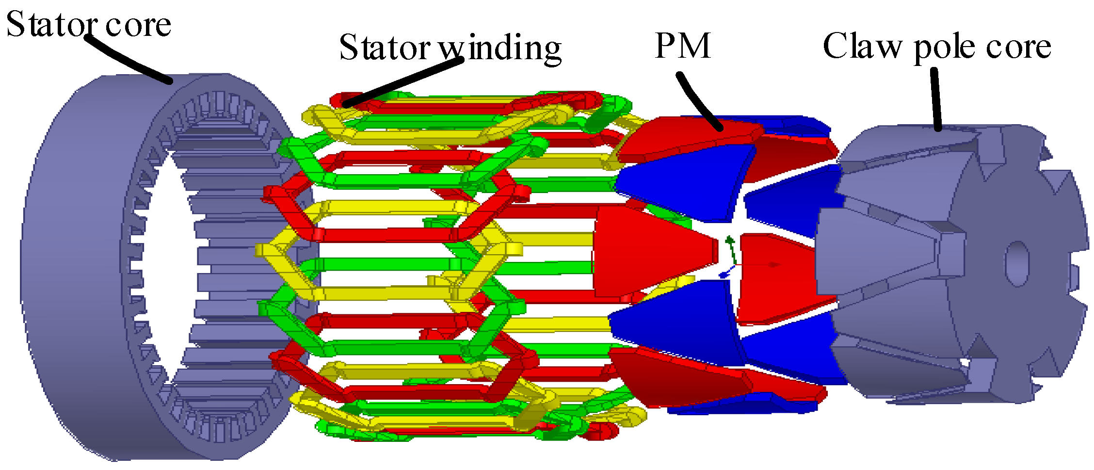
Figure 1. 3D model of the motor.
Machines 04 00015 g001
Figure 2. Mesh plot model of the core.
Machines 04 00015 g002
Figure 3. Magnetic circuit of the motor.
Machines 04 00015 g003
Figure 4. Output torque versus the thickness of l1 and l2.
Machines 04 00015 g004
Figure 5. Output torque versus air-gap length l3.
Machines 04 00015 g005
Figure 6. Output torque ripple versus air-gap length l3.
Machines 04 00015 g006
Figure 7. Output torque curves with different PM thickness l4.
Machines 04 00015 g007
Figure 8. Output torque ripple curves with different PM thickness l4.
Machines 04 00015 g008
Figure 9. The slice contours of the output torque versus geometrical parameters.
Machines 04 00015 g009
Figure 10. The air-gap flux density waveform (a) of the CPM and its harmonic analysis (b).
Machines 04 00015 g010
Figure 11. Output torque comparison curves before and after optimization.
Machines 04 00015 g011
Figure 12. Cogging torque curves with different materials.
Machines 04 00015 g012
Figure 13. Core loss curves with different materials.
Machines 04 00015 g013
Table 1. The essential parameters of (CPM).
Rated power (kW)3
Input current (A)100
Speed (RPM)500
Magnet typeNdFe35
Output torque (N·m)56.54
Frequency (Hz)50
Poles12
Number of stator slots36
Table 2. Performance results with different materials.
ParameterSMCDW360
Kh657.3168
Ke00
Kc0.090.8
Output torque of full-load (N·m)56.5451.3
Average cogging torque (N·m)0.640.71
Output power (kW)2.962.68
Core loss (W)612.5
Copper loss (W)24.5724.57
PM Loss (W)1.61.6
Efficiency98.92%98.58%