Review

Problems in Assessment of Novel Biopotential Front-End with Dry Electrode: A Brief Review

1
DIETI "Federico II" the University of Naples, Naples 80120, Italy
2
BENS, The MARCS Institute, the University of Western Sydney, Kingswood, NSW 2747, Australia
*
Author to whom correspondence should be addressed.
Machines 2014, 2(1), 87-98; https://doi.org/10.3390/machines2010087
Submission received: 24 December 2013 / Revised: 10 February 2014 / Accepted: 17 February 2014 / Published: 25 February 2014
(This article belongs to the Special Issue Machinery Diagnostics and Prognostics)

Abstract

:
Developers of novel or improved front-end circuits for biopotential recordings using dry electrodes face the challenge of validating their design. Dry electrodes allow more user-friendly and pervasive patient-monitoring, but proof is required that new devices can perform biopotential recording with a quality at least comparable to existing medical devices. Aside from electrical safety requirement recommended by standards and concise circuit requirement, there is not yet a complete validation procedure able to demonstrate improved or even equivalent performance of the new devices. This short review discusses the validation procedures presented in recent, landmark literature and offers interesting issues and hints for a more complete assessment of novel biopotential front-end.

1. Introduction

Biopotential signals such as electrocardiogram (ECG), electroencephalogram (EEG), electromyogram (EMG) electroculogram (EOG), etc. are extensively used in clinical practice to assess the physical condition and health status of patients [1]. Although the diagnosis of diseases or abnormalities is still carried out in hospitals by expert practitioners, there is a modern trend of non-invasive, unobtrusive and long-lasting patient’s monitoring outside the clinical environment. This trend has surfaced over the last few years and led to the development of a number of non-invasive monitoring devices (i.e., [2,3]), which can also be personal or home-based.
This is particularly true for ECG and EEG (i.e., heart and cardiovascular disease monitoring and Brain Computer Interface). Thus, in order to comply with home monitoring requirements, many of those novel devices claim the capability of recording electrophysiological signals continuously, with none (or very little) signal degradation over time and without the need for expert supervision [3,4]. Although some of those new technologies have been previously reviewed (i.e., [5]), existing reviews focus on claims and technologies to achieve long-term monitoring and/or dry electrode. This review focuses on the methodology that authors have successfully employed over the past few years to achieve and demonstrate equivalent of even better recordings, as opposed to other existing and proven hardware devices.
Quite a few of those technologies have become commercially successful [6,7,8]. However, given the small number of subjects employed for each study, and the intrinsic resistance -towards the adoption of new techniques, the majority of the devices suitable for long-term monitoring are still relegated to restricted research fields and/or as experimental devices, despite the efforts of researchers and authors in validation experiments.
Most successful biomedical front-end validation approaches are reviewed, the similarities between techniques are highlighted, and possible guidelines for future biomedical front-end validation are suggested.
From the existing literature, it is possible to infer some common strategies for validating the performance of biomedical analogue front-ends: namely, (a) the quantitative measurement of electrical circuit characteristics (i.e., circuit gain, frequency response, etc.); (b) qualitative evaluation of common physiological signal (i.e., recording from a very small population of healthy subjects); and (c) comparative assessment with a reference device (i.e., performed by comparing biopotential recordings acquired at the same time or at different times by the novel device and an existing medical device employed in clinical environment).
In this review, we present and criticize the common traits of the qualitative measurement of electrical circuit characteristics, discussing the choices of designers in performing some specific bench tests; we also stress the importance of a quantitative and more standardized biopotential signal evaluation.

2. Device Evaluation and Comparison Methods

2.1. Quantitative Measurement of Electrical Circuit Characteristics (a)

A front-end circuit suitable for biopotential recording must meet only concise specifications regarding the frequency band suitable for a specific diagnostic application (e.g., 0.05–150 Hz band for diagnostic grade ECG). [2,4]. However, there are no stringent specifications about the whole frequency response, for example in the vicinity of the band limits (this can change the diagnostic information provided). Some studies provide the frequency response of the circuit as a bode plot (magnitude) [9,10,11,12,13,14,15,16,17].
Unfortunately, off-the-shelf patient signal generators which are used for the periodic test of medical equipment and also for biopotential amplifier evaluation do not provide a continuous set of frequencies to perform a full frequency sweep. Normally they provide only sine waves at few (e.g., 5–10), predetermined frequencies in the range of 0.01 to 150 [Hz], which is too few to properly cover the full extent of the bio-signal bandwidth [4]. Additionally, the so-called patient simulators are designed to provide a differential signal which suits the majority (but not the totality) of biopotential front-ends. Further, it should be noted that the patient signal generators are designed to test the response of the circuit without the electrodes, which for some devices are incorporated into the design [13,18,19]. However, as evident in some designs, neither electrodes nor physical contact are necessary to achieve a biopotential recording [7,15,20,21].
Methods that test the frequency response of biomedical front-end that are different from a frequency sweep and based on the delay imposed to a well characterized pulsed wave (triangular and/or square) have been developed over the years, particularly for ECG recorders [22,23]. The evaluation methods based upon square and triangular pulse results are particularly useful to characterize overall performance of electrocardiographic equipment. The device under test needs to maintain negligible phase distortion to avoid the deformation of cardiac waveforms, while coping with the presence of abrupt voltage gradients (i.e., pacemaker pulses) [24,25]. However, comparison with fully artificially generated ECG signals (a normal feature of patient simulators) seems to supersede such a test and relegate it to the final stage of validation, prior to commercialization. Of note, since that there are commercially available low amplitude signal generators which should be able to generate the required sine wave sweep as well as the mentioned pulsed waveforms; a complete characterization of the frequency response of a front-end circuit for biopotential recording is important and desirable.
Aside from the gain and frequency response characteristics, a novel biopotential front-end usually includes information about power consumption [4,10,16,17,19,26,27,28,29]. In line with the growing demands of mobile monitoring [10,19], it is now a requirement that the power consumption of a monitoring device is at least in the order of a few µW. However, this requirement becomes not so compelling when the power consumption of interconnected circuits such as memorization or transmission devices [3,14,30] results higher (sometimes by orders of magnitude) than that of the biopotential front-end. Of note are several designers who reduced the power consumption of both the analogue and digital sections (sometimes including ADC) in order to break the barrier of the 1mW per biopotential front-end or channel [10].
Another important result that designers report in their specification table is the noise figure or noise-frequency relationship detailed plots. As it is known that some biomedical signals have important frequency content at very low frequencies (<0.5 Hz) [1,2,4], it is important that the proposed front-end exhibits particular high performance in terms of noise at very low frequencies. Additionally, since those biomedical front-ends will be interfaced to the employing electrode's source/the subject’s skin, it is important to consider the noise performance of the proposed front-end compared with the electrodes that will be recommended for use in combination with it [30,31]. As a general rule of thumb, it is possible to say that a biomedical front-end should exhibit a noise magnitude of 1.0 µVRMS or lower at very low frequencies (i.e., 1 Hz) in order to outperform at least the standard biomedical electrodes [32]. Despite the importance of information on noise performance, it is not always present in the specification summary of the proposed devices. Most importantly, the noise performance rarely includes the electrodes or the digital interface/transmitter, which is important information to give to the end user, particularly for custom made dry electrodes [15].
Input impedance value and its relationship to frequency is another desirable specification to have in the summary table of a biomedical front-end design. Most modern designs claim ultra-high input impedance [4,6,7,8,11,14,15,20] and dry electrode suitability. However, designers claiming ultra-high input impedance can only give an estimate of the input impedance (except [20]) and clarify that Printed Circuit Board (PCB) designs must be carefully engineered and manufactured to preserve the estimated value for input impedance [7,11,15]. A successful design solution, implemented in the Plessey sensors [6] to preserve the input impedance, provides the end user with a properly manufactured little PCB encapsulated into an epoxy shielded container. This solution ensures that the ultra-high input impedance value is within the estimated specifications. Alternatively, some innovative designs have been presented as ‘on-chip’ designs [20]. Designers deciding to integrate the full biomedical front-end on chip, while ensuring preservation of circuit characteristics, leave the PCB designer (the end user) with the burden of designing a circuit board which preserves the input impedance value and possibly requires further stages of amplification/filtering [6,20].
While the majority of the reviewed biomedical front-ends focus on the evaluation and demonstration of better recording capabilities of a single channel front-end; biopotentials often require simultaneous acquisition of multiple channels (i.e., multi-channels EEG and 12-lead ECG [33]). Unfortunately, aside from a few notable examples [15,34], multi-channel design recommendations (i.e., how to use the proposed design in real scenarios such as a full 10–20 EEG montage) are rarely addressed as designers focus on the evaluation of a single channel, implying that multi-channel application is a trivial extension of the design. Unfortunately, as a biomedical front-end needs to cope with large common mode noises (i.e., power line and harmonics noise) [1,35,36], issues on how to share a common reference (a common issue in EEG recording) and strategies on how to provide a proper grounding connection to the subject are rarely addressed and characterized by designers [15,16,37], even though they are known to be the cause of degradation of the Common Mode Rejection Ratio (CMRR). Often (see [29,38]) the CMRR is estimated and the circuit used for its estimation is presented. However, as mentioned above, this is a simple instrumentation exercise; for the majority of designs it only accounts for CMRR degradations because of the tolerance of the employed components. Of note, CMRR requirements are specified in the standard normative and biopotential amplifiers are needed to comply with the specified values and tests [22,23,39]. However, these tests are once again relegated to the final evaluation prior to commercialization.

2.2. Qualitative Physiological Signal Evaluation Characteristics (b)

Physiological signal recording capabilities of the proposed design are often qualitatively evaluated, presenting sample recordings usually from one, but occasionally a handful of healthy subjects. Although the evaluation of physiological signal recording capability performed using at least one subject may have a significant visual impact, it does not substitute a clinical evaluation of the proposed design. In paper reporting particularly there is a limited number of recording traces (sometimes only one); therefore, it is not clear how many subjects have actually been used and how the particular traces were selected among the various recordings.
In the case of ECG front-ends, there are not many features (aside from the raw presentation of traces) that benefit from the new design. In contrast, for EEG front-end designs, the most common elicited brain signal feature appears to be the alpha wave replacement phenomenon known to occur when a relaxed awake adult subject closes their eyes for few seconds [1]. As this test is very easy to perform, almost all the biopotential front-end reviewed claimed that EEG recording capabilities presented a ‘difference between eyes open and closed’ in the frequency domain.
While it is true that the alpha wave phenomenon is much more evident in the frequency domain [1,39], standard 5 or 10 second traces presenting the raw data together with a diagram or specific position from the 10–20 system could prove helpful in the visual evaluation of recordable data quality, particularly if physicians are targeted users [39]. Thus, designers should always include the time domain as well as the frequency domain plot of the alpha wave replacement phenomenon used for the evaluation.
Data excerpts representing raw data recorded from one or more subjects recorded several hours apart are particularly elucidative of the long-term monitoring capabilities of the proposed hardware, especially if they are accompanied by Signal to Noise Ratio (SNR) or other qualitative measurements [14,40]. Additionally, where new kinds of signals or novel recording techniques are presented, standard parallel recording of physiological data (although this may complicate the setup of devices) should always be presented [41,42].

2.3. Comparative Assessment with a Reference Device (c)

Qualitative biopotential signal evaluation is achieved performing parallel (acquired simultaneously) or serial (at different time) recordings against a commercial device (used in daily clinical practice or recognized (i.e., FDA approved) as suitable for it) considered as a reference [13,15,16,19,20,43,44,45]. It is normally performed in a hospital or clinical environment under the supervision of expert staff (ethical clearance and patients’ consent are usually required), and sometimes this evaluation precedes the proper clinical trial. As these kinds of recordings normally involve the use of multiple devices, the electrode placement can result problematic and cumbersome.
Other designers [20,46] assumed as a reference standard of their own front-end or pre-acquired data, recorded using standard gelled electrodes on prepared skin and assuming the noise figure of their amplifier to be lower than the standards gelled electrodes. Unfortunately, this raises doubt as to what exactly is accepted as a reference standard by designers.
For most of the reviewed devices, a parallel data acquisition was performed. Designers approaching this task face a number of challenges such as device synchronization, cross-talking and gain normalization; obviously, the correspondent electrodes of the two devices cannot be placed at exactly the same point. Furthermore, once the data is collected, designers must find a meaningful way to compare the recorded signal [14,15,30,47].
Device synchronization does not present much of a problem and can be solved by acquiring a common artificially generated signal (i.e., a coded sequence of pulses); it can also be achieved by artefact synchronization. For example, during parallel EEG recordings, practitioners can ask the subject to perform some distinctive actions such as eye blinking or jaw clenching, which can later be used to perform recording synchronization [15].
Crosstalk between devices can be an issue, particularly when two distinct ECG devices need to share common grounding connections (normally a driven ground configuration and often referred to as Driven Right Leg or DRL [1,37]). Without delving into the advantages and disadvantages of this well known technique, it is possible to understand that two different amplifiers connected to different pairs of electrodes (even if very close) may measure a different common mode signal, hence generating a crosstalk through the shared ground connections.
This issue can be solved efficiently by employing ECG front-end designs that do not use a DRL; or by avoiding the connection of the DRL, assuming that under controlled and shielded environments, the CMRR of the front-ends is high enough to measure an accurate ECG. Alternatively, assuming that the input impedance of the front-end is high enough, the same pair of electrodes can be employed (front-ends in parallel connection) [41]. Alternatively, signals recorded from the two devices need to be carefully evaluated. An example of careful signal evaluation in the case of parallel recordings performed on volunteer subjects and on a fully sedated animal model during a cardiac catheterization is described in [42,43]. In both studies, the machines were connected serially (one after the other) and disconnected in reverse order; the frequency content of biopotential signals recorded by each device was analyzed, comparing when the machines were alone to when they were connected, and ensuring none or negligible effect over reciprocal signal recording capabilities. Additionally, signals were scored and evaluated by trained medical staff present during the procedures.
For EEG recordings, from the existing literature [15,30,47], it is possible to gather that given the known high correlation of brain signals during elicited tasks [15,30,47], a practical way to test EEG front-ends in parallel is to surround each electrode connected to the device under test with a number of electrodes connected to the reference device. Then evaluate the correlation between the signal recorded by the device under test and each of the signals recorded by the reference device, as well as their average which in both cases should score very high (i.e., >0.9) [15,30].
As an additional test, EEG devices can be compared serially. This can be done using elicited features such as Somato-Sensory Evoked Potential (SSEP) which compares the timing and amplitude of recorded potentials from exactly the same 10–20 standard locations [15].

3. Recommendations and Comments

As already mentioned, frequency response of biopotential front-ends must be evaluated and tailored to the specific target signal. Hence, before starting the physiological signal evaluation, a full instrumental characterization of both (the reference and the ‘under-test’) devices is mandatory. Additionally, where possible, the frequency bandwidth of the device under test should be adjusted to replicate the reference device. This is not a simple task. In particular, the frequency response at the limits of the bandwidth may be significantly different because of use of dissimilar filters (by type and/or order), and also for the presence of not-excludable, hardware, notch filters (at power line frequency). In this case, a more accurate comparison between the recorded signals can be conducted after a software pre-processing (i.e., by applying high-order, zero phase lag filters) that limits the bandwidth to a subset of the original band (e.g. excluding the edges), in which the frequency response is surely more comparable. Similarly, frequency normalization should be applied as well for ECG front-end evaluation [15,19,41,42].
In the case of qualitative physiological signal evaluation performed using pre-recorded data (i.e., [46]), time correlation between signals could once again be used as a means of comparison. However, in this case designers should clarify how the test is coping with the natural physiological variability (i.e., heart rate variability in the case of the ECG) and this could raise other questions.
One can also note that qualitative physiological signal evaluation performed using only standard gelled electrodes, and the same analogue front-end under test (i.e., [20]) could be assimilated to merely compare the performances of electrodes [31]; hence, they may be less representative of the better recording capabilities, unless the electrodes are part of the design and properly characterized together with the analogue front-end [11,15,46,48].
In summary, from the reviewed literature it is possible to suggest some general guidelines which, aside from that of the standards, can be used when performing the evaluation of novel biopotential front-ends. Namely, almost all of the reviewed front-end circuits have been fully characterized (evaluation a). Not all of the authors presented the full extent of quantitative physiological signal evaluation. However, they have all been able to give a statement on the improvements in recording capabilities for their designs. This is summarized in the following Table 1 where the specifications and evaluation results presented in the reviewed studies are reported in a synoptic way.
As it is possible to infer from the table, although there is an apparent lack of uniformity in what designers think is compelling or necessary when they present the performance of their designs, almost all of them address the quantitative circuit evaluation to demonstrate their circuit as fit for biopotential recordings, such as circuit bandwidth, input impedance and noise figure. Aside from the synoptic Table 1, we also ordered the reviewed landmark literature onto a schematic roadmap (see Figure 1). As it is possible to infer from the roadmap, the very first bold step towards a proper characterization of a biopotential amplifier which claimed enhanced capabilities (dry and contactless) was in 2002 [7]. Since then, starting in 2008 (after a six year gap), every year at least one landmark paper has presented a novel amplifier with improved recording capabilities (see Table 1). The trend was not broken in 2013, where, although, the authors claim that the tests are far from being completed (hence we have not reviewed it in details), another improved dry electrodes amplifier for single ended recording was presented [42,43]. We also note that a larger time gap is present for the contactless feature. Remote (contactless), recording of bio potentials showing excerpt of data have been presented in 2002 [7] (1 m of distance detection of ECG) and then in 2010 [15] (EEG recorded with interposition of insulation layer). Unfortunately, there is not a standard in testing the quality of contactless electrodes and only in [15] authors make the effort to characterize the artifact as well as the clean biopotential recordings against a comparison device. Therefore, we reviewed those as only “dry” electrodes.
We conclude that, aside from the table with electronic characterization of the proposed novel front-end, a proper quantitative physiological signal evaluation also showing raw traces can add more information to claims such as the long-term monitoring of contactless recordings to facilitate their clinical acceptance. Of course, quantitative and qualitative evaluations of physiological signals do not represent a substitute to mandatory tests of compliance with the technical standards and proper multi-centre pre-clinical studies.
Table 1. Synoptic table of the assessment of biopotential front-ends performed by the reviewed literature.
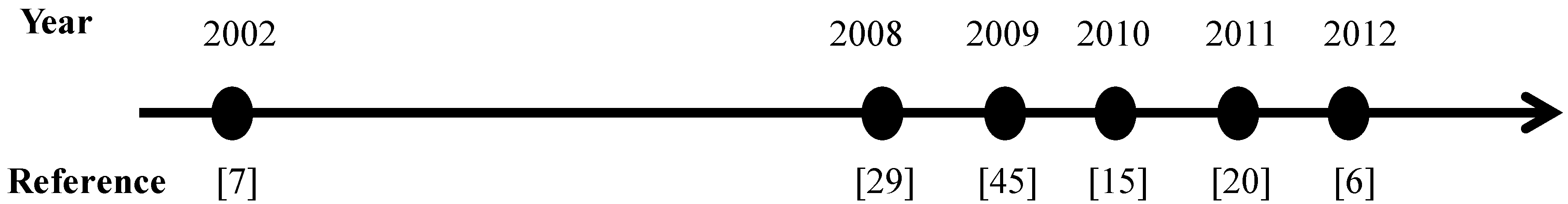
Reference—Type of Signal—Type of Electrodes RecommendedCustom Chip Design/Off—Shelf ComponentsInput Impedance—Noise FigurePower Consumption and Power Supply RangeMultichannel Design AvailableType of Evaluation (a, b, c). See Introduction
[6]—ECG, EEG, EMG—integrated dry electrodeBoth20 GΩ//15 pF—marked as 'to be defined'Bipolar ±2.4 V to ±4 V
2.5 mA supply current
NAa: only gain and bandwidth are declared
[7]—ECG, EEG, EMG—contactless and dry electrodesMade with off-shelf component (also basic schematic of Plessey [6])15 GΩ estimated at 1 Hz—70 nV/Hz estimated at 1 HzNANAa: bandwidth and noise
b: ECG recordings in parallel with photo-plethysmographic device
[15]—EEG—contactless and dry electrodesMade with off-shelf component (custom PCB design)>15 TΩ//2 pF —noise estimation at 10 Hz (include electrodes and digital transmitterUnipolar/bipolar up to ±18 V (limited to 3.3 V due to wireless transmitter)
Current consumption: <1 mA per channel
Yes (fully described in prior art: [19]a, b, c: full electronic characterization (no CMRR), qualitative evaluation of signal performed by neurophysiologist, 8 + 3 subjects for parallel evaluation against two different sample devices
[29]—ECG, EEG, EMG—standard electrodesMade with off-shelf componentNA2.7 to 5.5 V
Current consumption: 150 µA
NAOnly a (include CMRR characterization) and partial b, one single ECG shown
[20]—ECG, EEG, EMG—dry electrodesCustom chip and custom PCB design50 TΩ//60 fF
200 nV/Hz estimated at 1 Hz
3.3 V
Current consumption:
1.5+3.3 µA
Not showna (include CMRR); b (no EEG traces in time domain shown)
[45]—EEG—dry electrodesNANA (although the device is commercially available authors should have provided a summary of specifications)NAYesb, c: Authors calculate correlation between wet and dry electrodes similarly as shown in [15]
Figure 1. Synoptic roadmap of the landmark reviewed literature.
Machines 02 00087 g001

Author Contributions

All co-authors equally contributed in reviewing the state of the art literature and to the text editing.

Conflicts of Interest

The authors declare no conflict of interest.

References

  1. Webster, J.G. Medical Instrumentation Application and Design; John Willey: Hoboken, NJ, USA, 1998. [Google Scholar]
  2. Prutchi, D.; Norris, M. Design and Development of Medical Electronic Instrumentation; John Willey: Hoboken, NJ, USA, 2005. [Google Scholar]
  3. Gargiulo, G.D.; Bifulco, P.; Calvo, R.A.; Cesarelli, M.; Jin, C.; McEwan, A.; van Schaik, A. Electronic Biosensor Circuits and Systems. In Intelligent and Biosensors; Somerset, V.S., Ed.; IN-TECH: Rijeka, Croatia, 2010. [Google Scholar]
  4. Gargiulo, G.D.; Bifulco, P.; Calvo, R.A.; Cesarelli, M.; McEwan, A.; Jin, C.; Ruffo, M.; Romano, M.; Shephard, R.; van Schaik, A. Giga-Ohm High-Impedance FET Input Amplifiers for Dry Electrode Biosensor Circuits and Systems. In Integrated Microsystems Electronics, “Photonics, and Biotechnology”; Iniewski, K., Ed.; CRC Press: Boca Raton, FL, USA, 2011. [Google Scholar]
  5. Chi, Y.M.; Jung, T.-P.; Cauwenberghs, G. Dry-Contact and Noncontact Biopotential Electrodes: Methodological Review. IEEE Rev. Biomed. Eng. 2010, 3, 106–119. [Google Scholar]
  6. PS25203B EPIC Ultra High Impedance Electrophysiological Sensor, Technical Data; Plessey Company Inc: Fairport, NY, USA, 2012.
  7. Harland, C.J.; Clark, T.D.; Prance, R.J. Electric potential probes—New directions in the remote sensing of the human body. Meas. Sci. Technol. J. 2002, 13, 163–169. [Google Scholar] [CrossRef]
  8. Gargiulo, G.D.; Shephard, R.W.; Tapson, J.; McEwan, A.L.; Bifulco, P.; Cesarelli, M.; Jin, C.; Al-Ani, A.; Wang, N.; van Schaik, A. Pregnancy detection and monitoring in cattle via combined foetus electrocardiogram and phonocardiogram signal processing. BMC Vet. Res. 2012, 8, 164. [Google Scholar] [CrossRef]
  9. Degen, T.; Jäckel, H. A Pseudodifferential Amplifier for Bioelectric Events With DC-Offset Compensation Using Two-Wired Amplifying Electrodes. IEEE Trans. Biomed. Eng. 2006, 53, 300–310. [Google Scholar]
  10. Chi, Y.M.; Cauwenberghs, G. Micropower Non-Contact EEG Electrode with Active Common-Mode Noise Suppression and Input Capacitance Cancellation. In Proceedings of 31st Annual International Conference of the IEEE EMBS, Minneapolis, MN, USA, 2–6 September 2009.
  11. Prance, R.J.; Debray, A.; Clark, T.D.; Prance, H.; Nock, M.; Harland, C.J.; Clippingdale, A.J. An ultra-low-noise electrical-potential probe for human-body scanning. Meas. Sci. Technol. J. 2000, 11, 291–297. [Google Scholar] [CrossRef]
  12. Burke, M.J.; Gleeson, D.T. A Micropower Dry-Electrode ECG Preamplifier. IEEE Trans. Biomed. Eng. 2000, 47, 155–162. [Google Scholar] [CrossRef]
  13. Gargiulo, G.; Bifulco, P.; Calvo, R.A.; Cesarelli, M.; Jin, C.; van Schaik, A. Mobile Biomedical Sensing with Dry Electrodes. In Proceedings of IEEE ISSNIP, Sydney, Australia, 15–18 December 2008.
  14. Gargiulo, G.; Bifulco, P.; Cesarelli, M.; Romano, M.; Ruffo, M.; Calvo, R.A.; Jin, C.; van Schaik, A. An Ultra-high Input Impedance ECG Amplifier for Long Term Monitoring of Athletes. Med. Devices Evid. Res. 2010, 5, 1–9. [Google Scholar]
  15. Gargiulo, G.; Calvo, R.A.; Bifulco, P.; Cesarelli, M.; Jin, C.; Mohamed, A.; van Schaik, A. A new EEG recording system for passive dry electrodes. Clin. Neurophysiol. 2010, 121, 686–693. [Google Scholar] [CrossRef]
  16. Gargiulo, G.; Cohen, G.; McEwan, A.; Oh, T.I.; Mohamed, A.; Tapson, J.; Nguyen, D.T.; van Schaik, A.; Wabnitz, A. Active electrode design suitable for simultaneous EIT and EEG. Electron. Lett. 2012, 48, 25. [Google Scholar] [CrossRef]
  17. Spinelli, E.M.; Martínez, N.; Mayosky, M.A.; Pallàs-Areny, R. A Novel Fully Differential Biopotential Amplifier With DC Suppression. IEEE Trans. Biomed. Eng. 2004, 51, 1444–1448. [Google Scholar]
  18. Paradiso, R.; Loriga, G.; Taccini, N. A wearable health care system based on knitted integrated sensors. IEEE Trans. Inform. Technol. Biomed. 2005, 9, 337–344. [Google Scholar] [CrossRef]
  19. Gargiulo, G.; Bifulco, P.; Calvo, R.A.; Cesarelli, M.; Jin, C.; van Schaik, A. A Mobile EEG System with Dry Electrodes. In Proceedings of IEEE Biomedical Circuits and Systems Conference (BIOCAS), Baltimore, MD, USA, 20–22 November 2008.
  20. Chi, Y.M.; Maier, C.; Cauwenberghs, G. Ultra-High Input Impedance, Low Noise Integrated Amplifier for Noncontact Biopotential Sensing. IEEE J. Emerg. Sel. Top. Circuits Syst. 2011, 1, 526–535. [Google Scholar] [CrossRef]
  21. Prance, R.J.; Beardsmore-Rust, S.; Aydin, A.; Harland, C.J.; Prance, H. Biological and Medical Applications of a New Electric Field Sensor. In Proceedings of the 2008 ESA Annual Meeting on Electrostatics, Minneapolis, MN, USA, 17–19 June 2008.
  22. ANSI. Medical Electrical Equipment—Part 2–27: Particular Requirements for the Basic Safety and Essential Performance of Electrocardiographic Monitoring Equipment; IEC 60601-2-27:2011; AAMI: Arlington, VA, USA; p. 83.
  23. Bailey, J.J.; Berson, A.S.; Garson, A.; Horan, L.G.; Macfarlane, P.W.; Mortara, D.W.; Zywietz, C. Recommendations for Standardization and Specifications in Automated Electrocardiography: Bandwidth and Digital Signal Processing. Circulation 1990, 81, 730–739. [Google Scholar] [CrossRef]
  24. Assambo, C.; Burke, M.J. Low-Frequency Response and the Skin-Electrode Interface in Dry-Electrode Electrocardiography. In Advances in Electrocardiograms—Methods and Analysis; Millis, R.M., Ed.; INTECH: Rijeka, Croatia, 2012. [Google Scholar]
  25. Bonow, R.O.; Mann, D.L.; Zipes, D.P.; Libby, P.; Braunwald, E. Braunwald’s Heart Disease: A Textbook of Cardiovascular Medicine, 9th ed.; Elsevier: Amsterdam, The Netherlands, 2012; Volume 1. [Google Scholar]
  26. Levinzon, F.A. Ultra-Low-Noise High-Input Impedance Amplifier for Low-Frequency Measurement Applications. IEEE Trans. Circuits Syst. 2008, 55, 1815–1822. [Google Scholar] [CrossRef]
  27. Bermúdez, A.N.; Spinelli, E.M.; Muravchik, C.H. Biopotential amplifier for potential gradient measurements. J. Phys. 2007, 90, 012022. [Google Scholar]
  28. Spinelli, E.M.; Martinez, N.H.; Mayosky, M.A. A Transconductance Driven-Right-Leg Circuit. IEEE Trans. Biomed. Eng. 1999, 46, 1466–1470. [Google Scholar] [CrossRef]
  29. Dobrev, D.P.; Neycheva, T.; Mudrov, N. Bootstrapped two-electrode biosignal amplifier. Med. Biol. Eng. Comput. 2008, 46, 613–619. [Google Scholar] [CrossRef]
  30. Mihajlovic, V.; Molina, G.G.; Peuscher, J. To What Extent Can Dry and Water-Based EEG Electrodes Replace Conductive Gel Ones? A Steady State Visual Evoked Potential Brain-Computer Interface Case Study. In Proceedings of International Conference on Biomedical Engineering (ICBE 2011), Wuhan, China, 10–12 May 2011.
  31. Baba, A.; Burke, M.J. Measurement of the electrical properties of ungelled ECG electrodes. Int. J. Biol. Biomed. Eng. 2008, 2, 89–97. [Google Scholar]
  32. Huigen, E.; Peper, A.; Grimbergen, C.A. Investigation into the origin of the noise of surface electrodes. Med. Biol. Eng. Comput. 2002, 40, 332–338. [Google Scholar] [CrossRef]
  33. Malmivuo, J.; Plonsey, R. Bioelectromagnetism—Principles and Applications of Bioelectric and Biomagnetic Fields; Oxford University Press: Oxford, UK, 1995. [Google Scholar]
  34. TexasInstruments. Low-Power, 8-Channel, 24-Bit Analog Front-End for Biopotential Measurements, Technical Data. 2012.
  35. Metin, A. Wiley Encyclopedia of Biomedical Engineering; Wiley & Sons, Inc.: Hoboken, NJ, USA, 2006. [Google Scholar]
  36. Joseph, D.B. The Biomedical Engineering Hand Book, 2nd ed.; Bronzino, J.D., Ed.; CRC Press: Boca Raton, FL, USA, 2000; Volume 1. [Google Scholar]
  37. Winter, B.B.; Webster, J.G. Reduction of Interference Due to Common Mode Voltage in Biopotential Amplifiers. IEEE Trans. Biomed. Eng. 1983, BME-30, 58–62. [Google Scholar] [CrossRef]
  38. Spinelli, E.M.; Pallàs-Areny, R.; Mayosky, M.A. AC-Coupled Front-End for Biopotential Measurements. IEEE Trans. Biomed. Eng. 2003, 50, 391–395. [Google Scholar] [CrossRef]
  39. American Clinical Neurophysiology Society. Guideline 1: Minimum technical requirements for performing clinical electroencephalography. J. Clin. Neurophysiol. 2006, 23, 86. [Google Scholar] [CrossRef]
  40. Gargiulo, G.; Bifulco, P.; Cesarelli, M.; Jin, C.; McEwan, A.; van Schaik, A. Wearable Dry Sensors with Bluetooth Connection for Use in Remote Patient Monitoring Systems. Stud. Health Tech. Info. 2010, 161, 57–65. [Google Scholar]
  41. Gargiulo, G.D.; Tapson, J.; van Schaik, A.; McEwan, A.; Thiagalingam, A. Unipolar ECG Circuits: Towards More Precise Cardiac Event Identification. In Proceedings of 2013 IEEE International Symposium on Circuits and Systems (ISCAS), Beijing, China, 19–23 May 2013; pp. 662–665.
  42. Gargiulo, G.; McEwan, A.; Bifulco, P.; Cesarelli, M.; Jin, C.; Tapson, J.; Thiagalingam, A.; van Schaik, A. Towards true unipolar ECG recording without the Wilson Central Terminal (Preliminary results). Physiol. Meas. 2013, 34, 991–1012. [Google Scholar] [CrossRef]
  43. Gargiulo, G.; McEwan, A.; Bifulco, P.; Cesarelli, M.; Jin, C.; Tapson, J.; Thiagalingam, A.; van Schaik, A. Towards true unipolar biopotential recording: A preliminary result for ECG. Physiol. Meas. 2012, 34. [Google Scholar] [CrossRef]
  44. Velis, D.; Plouin, P.; Gotman, J.; da Silva, F.L. Recommendations Regarding the Requirements and Applications for Long-term Recordings in Epilepsy. Epilepsia 2007, 48, 379–384. [Google Scholar] [CrossRef]
  45. Estepp, J.R.; Monnin, J.W.; Christensen, J.C.; Wilson, G.F. Validation of a Dry Electrode System for EEG, in Human Factors and Ergonomics Society. Proc. Hum. Factors Ergonomics Soc. Ann. Meet. 2009, 53, 1171–1175. [Google Scholar] [CrossRef]
  46. Wang, I.-J.; Liao, L.-D.; Wang, Y.-T.; Chen, C.-Y.; Lin, B.-S.; Lu, S.-W.; Lin, C.-T. A Wearable Mobile Electrocardiogram Measurement Device with Novel Dry Polymer-based Electrodes. In Proceedings of 2010 IEEE Region 10 Conference (TENCON 2010), Fukuoka, Japan, 21–24 November 2010; pp. 379–384.
  47. Iguchi, H.; Watanabe, K.; Kozato, A.; Ishil, N. Wearable Electroencephalograph system with preamplifier electrodes. Med. Biolog. Eng. Comput. 1994, 32, 459–461. [Google Scholar] [CrossRef]
  48. Alizadeh-Taheri, B.; Smith, R.L.; Knight, R.T. An active microfabricated scalp electrode array for EEG recording. Sens. Actuators 1996, 54, 606–611. [Google Scholar] [CrossRef]

