Abstract
Currently, the dismantling of aluminum stranded conductors remains predominantly manual due to their structural complexity. To enhance the efficiency and reduce the labor intensity for dismantling aluminum stranded conductors, this study presents an innovative torque-driven dismantling method validated through dynamic simulation analysis. To demonstrate the proposed method, a modular prototype machine that includes four main functional modules (transmission, untwisting, separation, and shearing) was developed. Experimental results from the prototype dismantling machine demonstrated that when processing JL/G3A-500/65 conductors (Sichuan Star Cable Co., Ltd., Leshan, China) under the following operational parameters—0.5 rad/s rotational speed, 10 cm extension length, 2400 N clamping force, and 40 N·m torque application—the system achieved a single-layer dismantling efficiency exceeding 98%. This represents a significant improvement in operational speed compared to traditional manual methods. The developed machine achieved collaborative control of axial feed, reverse untwisting, and automatic shearing, elevating the untwisting qualification rate to 95%. This solution provides an efficient and safe approach to conductor inspection, demonstrating substantial engineering application value.
1. Introduction
In recent years, with the advancement of China’s “Dual Carbon” goals and accelerated energy structure transition, ultra-high voltage (UHV) power grids have emerged as critical network infrastructures supporting national strategic initiatives such as “West-East Power Transmission” and “new energy grid integration”. By 2025, the State Grid Corporation of China will have completed and operationalized 35 UHV projects, achieving an annual electricity transmission capacity exceeding 3 trillion kilowatt-hours, which significantly enhances inter-regional power allocation capabilities. Overhead transmission lines, leveraging their economic efficiency and adaptability advantages, undertake more than 90% of national power transmission tasks, serving as the “arterial network” of the power system. The aluminum conductor steel-reinforced (ACSR) cables predominantly employed in high-voltage and UHV overhead transmission systems feature a composite structure of steel cores and aluminum strands. This innovative configuration achieves synergistic optimization of mechanical strength and electrical conductivity, establishing its dominance in high-voltage and UHV transmission applications [1,2,3].
The widespread adoption of ACSR cables stems from their dual-functional advantages: the internal steel core effectively withstands extreme meteorological conditions in heavy-ice zones and long-span configurations while bearing mechanical stresses in both large-span and conventional installations. Concurrently, the outer aluminum strands reduce overall resistivity and enhance current-carrying capacity, fulfilling long-distance power transmission requirements. A representative application is evidenced in the Xinjiang-to-Chongqing ±800 kV UHV DC transmission project, where large-section ACSR cables with enhanced reliability effectively mitigate conductor fracture risks induced by complex southwestern terrain and high-altitude conditions. This project achieves an annual average transmission capacity exceeding 12,000 megawatts [4,5].
Given the extensive application of ACSR cables in China’s power transmission systems, ensuring their quality through essential testing has become critical to maintaining national electricity delivery reliability. The advanced infrastructure of China’s power grid necessitates substantial annual investments in human and material resources for ACSR inspection. Conventional manual sampling procedures involving physical separation and dimensional measurements significantly constrain testing efficiency while introducing safety risks. Furthermore, inspection personnel simultaneously handle critical engineering evaluations, coiled cable assessments, concrete pole inspections, and hardware/tower examinations, creating operational bottlenecks that limit workforce utilization and testing capacity enhancement [6,7].
The widespread deployment of ACSR cables has driven technological advancements in conductor separation. In 2017, Hubei Jinyang Resources Co., Ltd., developed a disassembly system [8] with three functional modules: a power transmission unit (electric motor), a conductor management unit (wire-aligning drum, cable spools), and an unwinding mechanism (drive wheels, rotating arms). This system employs reverse unwinding principles: steel cores are axially drawn through aligning drums onto third spools, while aluminum strands are subdivided and wound onto primary/secondary spools via rotating arms that execute counter-rotational motions perpendicular to the drum axis. Although this method improves unwinding efficiency, it results in high residual interface contamination (12–15% mass fraction), necessitating additional post-processing. A structural breakthrough emerged in 2020 with Xinghua Senrong Metal Products Co., Ltd.’s modular separation device [9], which integrates three-stage operational units: clamping mechanisms (self-locking fixtures, worm-gear transmission), rotational systems (ball screw-driven sliding modules), and separation assemblies (sector-rack-actuated stripping claws). This patented technology achieves a 2.1× improvement in end-stripping effectiveness through axial preloading and circumferential unwinding. However, practical implementation faces challenges, including excessive power system redundancy (six-stage transmission chain) and the lack of automatic wire collection, leading to high energy consumption (1.2 kWh/t) that hinders industrial scalability.
The dismantling of aluminum conductor steel-reinforced (ACSR) cables has been extensively investigated through multiple approaches, each presenting distinct advantages and limitations. Mechanical untwisting techniques, as demonstrated in conductor recycling research, have shown effectiveness at 20–40% of the theoretical critical torque (typically 80–100 N·m), preserving 95% of original aluminum strand properties for reuse in power distribution lines. While this method maintains material integrity, previous studies have overlooked plastic strain localization effects, a critical gap addressed in our current finite element analysis. Alternative thermal-assisted separation methods, though effective for polymer–matrix composites at 550 °C [10], prove detrimental for ACSR by reducing aluminum’s post-recovery tensile strength by 15–20% through annealing effects, while consuming significantly more energy (0.2–0.3 kWh/m versus 0.015–0.025 kWh/m for mechanical methods). Corrosion-assisted approaches, while reducing dismantling forces by 25–35% through interfacial weakening, introduce material recovery challenges due to non-uniform corrosion patterns. Industrial cutting solutions, despite their rapid processing, result in 5–8% material loss and geometric distortion, contrasting sharply with the torque-based method’s complete geometric retention.
To address these limitations, this study proposes a nondestructive dismantling equipment solution based on modular architecture and numerical simulation technologies. A hierarchical framework was constructed through an object-oriented design methodology, functionally decomposed into motion control, mechanical loading, and separation modules [11,12,13,14]. Finite element simulations were implemented for the topological optimization and dynamic validation of critical components. Following prototype development and experimental platform establishment, module-specific functional validations were conducted through parameterized testing. Ultimately, system integration principles synchronize wire feeding, unwinding, and shearing operations to create an integrated disassembly system that increases processing throughput by 38–45% over conventional methods. By comparison, disassembling each aluminum strand using traditional methods costs approximately USD 4, while the proposed automated disassembly method costs only about USD 0.5 per strand, which significantly reduces the cost.
2. Methods and Working Principle
ACSR is fabricated by helically stranding an inner steel core and outer aluminum strands [15], which is shown in Figure 1a. The intelligent conductor dismantling equipment developed in this study separates aluminum strands from the steel core based on reverse-stranding mechanical principles, specifically utilizing the interlayer residual stranding stress formed during aluminum strand manufacturing. This process applies torque loads in the direction opposite to the original stranding orientation, enabling the gradual elastic untwisting of aluminum strands within their deformation limits to achieve layer-by-layer decoupling. The dismantling working principle consists of three sequential aspects:
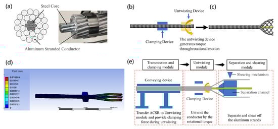
Figure 1.
(a) The structural schematics of the aluminum conductor steel-reinforced (ACSR) conductor; (b) the torque-based disassembly methodology for the ACSR conductor; (c) the untwisted aluminum strands after the disassembly process; (d) the finite element simulation result of strain distribution; (e) the workflow of the rapid dismantling for ACSR conductors.
- (1)
- Torque transmission: A torque transmission mechanism is established according to structural parameters of the stranded conductor (aluminum layer lay ratio, stranding direction, and layer count) to determine the critical torque required for progressive aluminum strand unwinding.
- (2)
- Controlled reverse torque application: A servo-driven system applies precisely regulated counter-directional torque to the stranded conductor, generating physical reverse shear strain within aluminum layers to counteract the original residual stranding stress.
- (3)
- Multi-stage torque unloading: A graded torque reduction method is implemented through multi-level unloading sequences to progressively disengage aluminum strands layer by layer.
Figure 1b illustrates the torque-based disassembly methodology for aluminum conductor steel-reinforced (ACSR) wire proposed in this study. When the aluminum stranded wire is conveyed to the designated position, the clamping unit is first activated to secure one end of the wire. Subsequently, a counter-rotational torque, opposite to the stranding direction of the aluminum layers, is applied to the opposite end through the untwisting device to dismantle the outer aluminum strands. The ideal untwisted configuration of the aluminum strands under this methodology is depicted in Figure 1c. The torque-driven untwisting process requires overcoming both the plastic bonding forces between adjacent strands and the frictional resistance. Theoretically, the critical torque required to disassemble the outermost aluminum layer via this torque-based approach can be calculated as follows:
In the equation, N denotes the number of aluminum strands in the layer, represents the shear strength of the aluminum material (66.5 MPa), is the cross-sectional area of a single aluminum strand, is the coefficient of friction (0.15 for aluminum-to-aluminum contact), is the contact area between adjacent strands, signifies the residual compressive stress induced during stranding (typically 15–30 MPa), is the layer radius of the outer aluminum strands, and corresponds to the stranding angle. The contact area is calculated as follows:
In the equation, denotes the diameter of a single aluminum strand, and represents the length of the clamping portion of the untwisting device. The stranding angle α is determined by the following formula:
In the equation, denotes the lay length of the aluminum conductor steel-reinforced (ACSR) conductor. In the practical torque-driven untwisting of the outer aluminum strands, only elastic deformation and the overcoming of interlayer frictional forces are required to achieve strand untwisting. To validate the feasibility of the torque-based disassembly methodology for ACSR conductors, this study employed finite element analysis (FEA) software (ANSYS2020R2) for numerical simulation. The FEA model development procedure is structured as follows.
The finite element analysis incorporated a comprehensive modeling approach where material properties were rigorously defined, including the steel–aluminum friction coefficient (μ = 0.15) and aluminum–aluminum friction coefficient (μ = 0.12) based on the Coulomb friction model, with additional consideration given to the elastoplastic behavior of aluminum strands (yield strength: 120 MPa, hardening modulus: 1.2 GPa) and linear elasticity for the steel core (modulus: 210 GPa, Poisson’s ratio: 0.3). The meshing strategy employed structured hexahedral elements for the aluminum strands (global size: 2 mm, locally refined to 0.5 mm at contact zones) and quadratic tetrahedral elements (C3D10) for the steel core, ensuring aspect ratios below 5 and skewness limited to 0.7 to maintain numerical stability. Boundary conditions were carefully implemented by fully constraining all degrees of freedom at one end (ENCASTRE condition) to simulate the clamping device, while a progressive torque load was applied at the opposite end through a reference point (RP) using a smooth step amplitude curve to replicate quasi-static untwisting. Contact interactions were modeled using surface-to-surface formulation with penalty friction (stiffness ratio 1:10) and hard normal contact, supplemented with automatic stabilization (damping coefficient: 1 × 10⁻⁵) to enhance convergence. The explicit dynamic solver was selected to handle large rotations, with mass scaling applied to maintain a stable time increment below 1 × 10⁻⁶ s while keeping energy errors (ALLIE/ALLKE) under 5%. Post-processing focused on analyzing equivalent von Mises stress distribution and interfacial slip displacements, with particular attention to plastic strain localization in aluminum strands [16,17,18,19].
According to Equation (1), the critical torque for untwisting the ACSR conductor is calculated to be approximately 80 N·m. In the practical simulation, however, a torque of approximately 20 N·m successfully dismantled the outer aluminum strands. This discrepancy arises because the actual untwisting process requires overcoming only frictional resistance and elastic deformation, corresponding to 20–40% of the calculated theoretical value. The clamping force calculation for the clamping unit is derived from the static frictional torque equilibrium principle. When the untwisting device applies to a counter-rotational torque T, the clamping unit must generate sufficient static frictional torque to counteract T, thereby preventing relative slippage of the aluminum strands at the clamping interface [20]. Consequently, the clamping force F provided by the clamping unit must satisfy the following equation:
In the above equation, represents the safety factor, denotes the friction coefficient, is the radius of the aluminum stranded wire, and corresponds to the applied torque during the untwisting process.
Based on the aforementioned research findings, an intelligent modularized device for disassembling ACSR conductors via a torque methodology was developed. This system achieves a nondestructive separation of outer aluminum strands through functional decoupling and coordinated control, comprising three core functional modules (Figure 1d): ACSR conductor–transmission and clamping module, untwisting module, and separation–shearing module. The dismantling process initiates with the axial feeding of the ACSR conductor while a radial clamping force is applied to suppress interlayer slippage during untwisting. Subsequently, counter-rotational torque disrupts the helical configuration of adjacent aluminum layers, enabling progressive layer-by-layer disassembly. Finally, a separation and shearing module segregates and collects the untwisted strands.
3. Results and Discussion
3.1. Mechanism Design for Transmission and Clamping
The intelligent rapid disassembly and inspection apparatus for overhead conductors developed in this study comprises three core functional modules: a transmission module, an untwisting module, and a shearing module. The transmission module is designed to transport conductors while accommodating diameter variations through adjustable mechanisms. When the conductor to be disassembled is transferred to the untwisting module by the transmission system, the untwisting module clamps one end of the conductor and rotates the opposite end in a direction counter to the original stranding orientation, thereby decoupling the outer aluminum strands. Subsequently, the transmission module advances the conductor axially while the untwisting module maintains continuous rotational actuation. Upon completion of a layer’s untwisting process, the separation module physically isolates the disentangled aluminum strands. This procedure is iteratively repeated to sequentially untwist subsequent aluminum layers, achieving progressive layer-by-layer disassembly of the stranded conductor.
Steel-core aluminum stranded conductors (ACSR) represent the most extensively utilized core wire type in power transmission systems. The extensive variety of models is designed to fulfill precise electrical, mechanical, and environmental requirements across different application scenarios. From the perspective of a composite material structure, specification variations primarily manifest in four aspects: cross-sectional area ratio between aluminum strands and steel core, stranding configuration, wire diameter combinations, and surface treatment techniques.
As specified in international standards IEC 61089 [21], ASTM B232 [22], and China’s national standard GB/T 1179, ACSR models are conventionally denoted in an “aluminum cross-section/steel cross-section” format (e.g., ACSR-240/40). The cross-sectional area of aluminum strands typically ranges from 35 to 1000 mm2, with steel core proportions varying between 5% and 40% of the total cross-section depending on specific mechanical strength requirements. Fundamental parameters of selected ACSR configurations are summarized in Table 1.

Table 1.
Fundamental parameters of representative steel-core aluminum stranded conductors (ACSR).
As evident from the preceding Table 1, steel-core aluminum stranded conductors (ACSR) exhibit significant diversity in specifications, with a substantial variation in outer diameters across different models. To achieve adaptive conveyance of multi-specification and multi-category ACSR wires, this study proposes a modular conveyance system (see Figure 2) comprising a wire straightening and positioning unit and a dynamic clamping and transmission unit that operates under a collaborative operational mechanism.
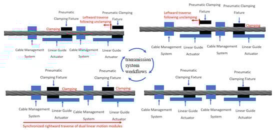
Figure 2.
Schematic diagram of the transmission system.
The workflow of this transmission module is as follows: when a preprocessed ACSR wire is positioned at the workstation, dual pneumatic machining vises are simultaneously actuated to clamp the wire. The ACSR wire is then conveyed rightward under the actuation of linear motion modules. Upon reaching the linear motion module’s stroke limit, the rear pneumatic vise is disengaged, allowing the module to execute a leftward traverse to predetermined coordinates. Subsequently, the rear vise is re-clamped, followed by the release of the front vise. The module then performs another leftward traverse to align the front vise with the target position, after which the front vise is clamped. Finally, the ACSR wire is advanced rightward under coordinated control of both linear motion modules. This sequence is iterated until the wire reaches the strand separation station for subsequent processing operations (the workflow is detailed in Figure 2).
Wire Straightening and Positioning Unit: This unit employs a multi-degree-of-freedom adjustable cable management frame structure, primarily consisting of cross-arranged vertical and horizontal displacement adjustment columns, along with radially equidistant adjustment columns (see Figure 3). It enables a continuous radial adjustment within a diameter range of φ5–φ50 mm. By applying a controllable straightening force to initially curved conductors, plastic deformation is induced. Simultaneously, the clamping plane elevation is adjusted to ensure the mass centroid of conductors with varying diameters remains collinear, thereby establishing a reference horizontal plane (error ≤ ±0.2 mm), which serves as the geometric datum for subsequent strand separation processes.
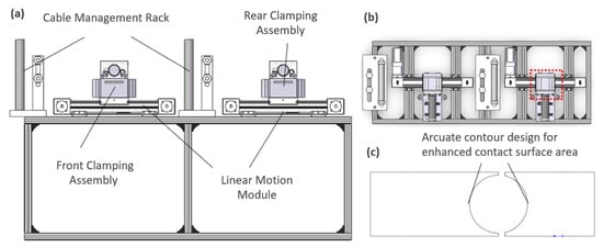
Figure 3.
Three-dimensional model of the transmission module. (a) Front view of the 3D model, (b) top view of the 3D model, and (c) arcuate fixture design illustrating enhanced contact geometry.
Dynamic Clamping and Transmission Unit: This compound transmission system integrates front/rear dual pneumatic clamping assemblies with high-precision linear motion modules. The front pneumatic gripper (adjustable clamping force: 0.5–100 kN) utilizes a mechanical locking mechanism to secure the aluminum strands, while the linear motion module (repositioning accuracy: ±0.01 mm) drives the terminal clamping assembly to execute axial incremental conveyance motion along predefined trajectories (conveyance speed: 0.1–3 m/min), propelling the aluminum strands along the feeding direction (Figure 3).
The rear clamping assembly additionally functions as a fixed constraint during the strand separation phase. Through static friction locking (friction coefficient μ ≥ 0.2), it provides reactive torque support for counter-rotational force application. A finite element-optimized arcuate clamping mechanism (contact stress distribution uniformity > 90%) suppresses conductor oscillations induced by separation torque, ensuring a torque transmission efficiency ≥ 95% within the strand separation module.
3.2. Mechanism Design for Untwisting
The ACSR conductor untwisting module employs a centrosymmetric dynamic torque-loading architecture, comprising a pneumatic central clamping mechanism, a hollow-shaft rotary drive system, and a closed-loop motion control unit, with its overall configuration illustrated in Figure 4a,b.
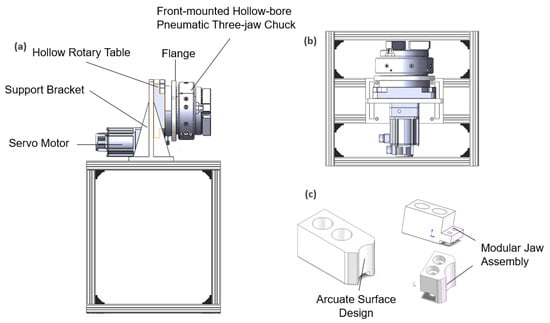
Figure 4.
Three-dimensional model of the strand separation module. (a) Front view of the 3D model, (b) top view of the 3D model, and (c) modular jaw assembly design.
The pneumatic central clamping mechanism employs a front-mounted hollow-bore three-jaw chuck with a clamping force range of 0.8–5.2 kN, featuring segmented tungsten carbide inserts and arcuate-surfaced jaws to maximize contact area and stability during strand separation operations. Designed for adaptive clamping of conductors spanning Φ10–Φ60 mm diameters, the system utilizes modular jaw assemblies with replaceable tips actuated by an integrated annular pneumatic actuator, ensuring precision grip adjustment (Figure 4c). Coupled with this mechanism is a hollow-shaft rotary drive system combining a high-precision servo motor and harmonic drive reducer, which transmits axial torque through a flanged hollow rotary table (Φ150 mm through-hole) while maintaining radial concentricity.
The untwisting process initiates with dual-end stabilization: a terminal pneumatic gripper secures the ACSR conductor via six-point contact fixation while the front chuck radially contracts to form a statically determinate constraint system. The servo motor then applies programmable counter-rotational torque corresponding to the conductor’s stranding direction (left/right-handed modes selectable via software). Following single-cycle separation, coordinated motor braking and chuck pressure release enable incremental advancement of the conductor by the feed module, with the sequence iterating cyclically until complete layer separation is achieved through progressive axial displacement.
3.3. Mechanism Design for the Separation
Following strand separation, the conductor is continuously advanced by the conveyance module. The post-separation configuration of the conductor is depicted in Figure 5a. To isolate the separated outer aluminum strands from the unprocessed inner strands, a dedicated separation channel is engineered. Upon reaching predefined coordinates, the separated aluminum strands are severed via controlled cutting tools.
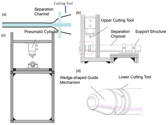
Figure 5.
Three-dimensional model of the separation and shearing module. (a) Schematic diagram showing the radial cutting mechanism. (b) Left view of the 3D model of the separation and shearing module. (c) Front view of the 3D model of the separation and shearing module. (d) Local magnification of the wedge-shaped guiding structure.
To achieve efficient separation and selective processing of post-separation ACSR components, a synergistic control strategy integrating mechanical sorting and intelligent shearing is implemented, with the workflow detailed below: The separated conductor is incrementally advanced along the axial direction by the conveyance module to the sorting station. At this stage, the conductor exhibits a stratified mechanical configuration: the outer aluminum strands adopt a helically expanded morphology, while the inner unprocessed core retains its twisted structure. Leveraging material stiffness disparities (elastic modulus of separated aluminum strands: 69 GPa; equivalent modulus of unprocessed composite core: ≥120 GPa), the separation channel is designed as a gradually tapered wedge-shaped guide structure (entry angle: 25° ± 1°, surface roughness Ra ≤ 0.8 μm). This geometry induces gradient contact stress distribution, enabling physical segregation between the outer separated aluminum strands and inner composite core, thereby enhancing separation efficiency.
The outer separated aluminum strands enter a radially servo-actuated shear station equipped with a single-degree-of-freedom pneumatic cutting tool (axial stroke: 0–400 mm, adjustable shear force: 0.1–1.2 kN) capable of selective strand severing (minimum shear unit length: 300 mm). When the conductor is positioned at the target coordinates, a three-jaw pneumatic chuck executes circumferential clamping, while a tungsten carbide tooling insert mounted on a pneumatically driven actuator performs radial cutting to sever the aluminum strands. Post-shearing, the chuck implements stepped rotational indexing (programmable angular increments: 5–360°). Through operator-supervised control, directional shearing cycles are iterated until complete layer-wise strand separation is achieved. The unprocessed inner core is subsequently retracted to the separation station via reverse conveyance, initiating the next hierarchical separation–sorting–shearing cycle. This methodology enables a progressive layer-by-layer strand separation of ACSR conductors.
To validate the module’s performance, finite element analysis (FEA) was conducted to simulate deformation during shearing. As illustrated in Figure 6b, the maximum deformation reaches approximately 1.5 mm (50% of the strand diameter), which critically compromises cutting reliability. Structural reinforcement is, thus, essential to mitigate deformation.
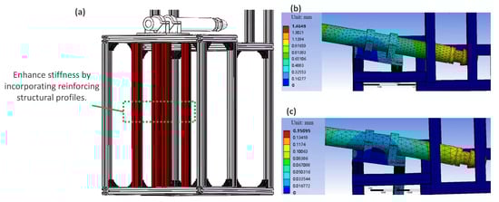
Figure 6.
(a) Stiffness-enhanced structural design, (b) deformation simulation of the separation channel pre-reinforcement, and (c) deformation simulation of the separation channel post-reinforcement.
A rigidity enhancement strategy was implemented by integrating four additional structural profiles beneath the cantilever beam to resist global deformation (Figure 6a). Post-optimization simulations demonstrate a reduced maximum deformation of 0.15 mm, achieving a tenfold improvement in structural stiffness and ensuring a consistent strand separation.
In addition to incorporating reinforcing profiles to enhance stiffness, the wall thickness of the separation channel itself critically influences the overall structural rigidity and deformation resistance. When subjected to transverse shear forces, the bending resistance of the channel is governed by the cross-sectional moment of inertia (I) and the material’s elastic modulus (E). For circular tubular geometries, the moment of inertia is calculated as follows:
where denotes the outer diameter of the channel, represents the inner diameter, and is the wall thickness:
When the outer diameter D remains constant, the moment of inertia I increases nonlinearly with wall thickness (I ∝ 3). It can, thus, be inferred that a smaller wall thickness reduces the moment of inertia and bending resistance, leading to greater deformation under equivalent loads. Conversely, a larger wall thickness enhances the moment of inertia and bending resistance, resulting in reduced deformation under identical loading conditions.
Assuming the separation channel of the shearing system can be simplified as a cantilever beam model (fixed at one end and subjected to transverse tooling loads at the free end), the maximum deflection max is expressed as follows:
where denotes the shearing force, is the elastic modulus, represents the moment of inertia, and is the cantilever length.
The above formulation reveals that a reduced wall thickness decreases the moment of inertia, thereby increasing the maximum deflection () and resulting in greater deformation under identical loading. Conversely, an increased wall thickness enhances the moment of inertia, reducing and minimizing deformation under equivalent loads.
To verify this relationship, numerical simulations were performed for four wall thickness variations (7.5 mm, 10 mm, 12.5 mm, and 15 mm) while maintaining a constant outer diameter of 70 mm. The shearing system utilized the stiffness-enhanced structural configuration with the shearing force of 1500 N. As shown in Figure 7a, the maximum deformation for the wall thickness of 15 mm is about 0.599 mm. This value is less than that for the wall thickness of 12.5 mm, which is 0.609 mm (Figure 7b). As the wall thickness decreases to 10 mm, the maximum deformation increases to 0.631 mm (Figure 7c). While the wall thickness of 7.5 mm leads to a severe deformation of 0.674 mm, which can be seen in Figure 7d.
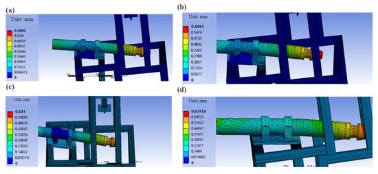
Figure 7.
Deformation simulations of the separation channel with varying wall thicknesses. (a) Wall thickness: 15 mm; maximum deformation: 0.599 mm. (b) Wall thickness: 12.5 mm; maximum deformation: 0.609 mm. (c) Wall thickness: 10 mm; maximum deformation: 0.631 mm. (d) Wall thickness: 7.5 mm; maximum deformation: 0.674 mm.
The numerical simulations demonstrate a progressive reduction in separation channel deformation with increasing wall thickness, which can be seen in Figure 8. Considering practical weight constraints and structural integrity requirements, the optimal wall thickness of the separation channel was determined to be 15 mm.
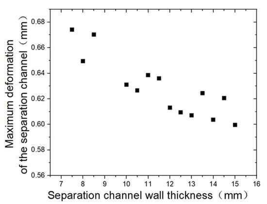
Figure 8.
Comparative analysis of deformation across the parametric wall thickness range.
3.4. Dismantling Testing
As demonstrated above, the dismantling of the ACSR conductor is realized by three modules: transmission–clamping, untwisting, and separation–shearing (Figure 9). The designed dismantling process includes the following steps:
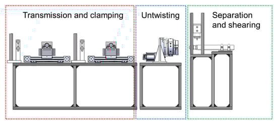
Figure 9.
Three-dimensional model of the prototype.
- (i)
- Preprocessing: The conductor to be disassembled is guided into the workstation via the cable management rack of the conveyance module. Axial centering is achieved by adjusting the rollers of the wire guiding frame.
- (ii)
- Transmission and clamping: The conductor is clamped by pneumatic machining vises and transported to the strand separation station at a constant velocity (V = 1 m/s) via linear motion modules.
- (iii)
- Untwisting: Upon reaching the separation station, the pneumatic vise clamps one end of the aluminum strand, while a three-jaw chuck secures the opposite end. A hollow rotary table applies counter-rotational torque to unwind the aluminum strands against their original lay direction.
- (iv)
- Separation and shearing: the conductor is advanced through the separation channel, segregating the separated outer strands from the unprocessed inner core. At the designated workstation, the three-jaw pneumatic chuck executes circumferential clamping, and a tungsten carbide cutting tool mounted on a pneumatically driven actuator performs radial shearing for cross-sectional separation. Following shearing, the chuck implements stepped rotational indexing (programmable angular increments: 5–360°). Spatial pose estimation of the aluminum strands is computed via coordinate transformation algorithms, enabling iterative directional shearing until complete layer-wise separation is achieved.
Compared to manual disassembly, this methodology significantly improves operational efficiency (cycle time reduction ≥60%) and enhances the quality of recovered aluminum strands (surface defect reduction ~35%).
Taking the JL/G3A-500/65 steel-reinforced aluminum conductor as an example, with an approximate overall diameter of 28 mm and 22 aluminum wires in its outermost layer, the critical torque required for disentangling the outermost aluminum wires was calculated as approximately 40 Nm based on the formula proposed in this study. The clamping mechanism, designed with an arc-shaped configuration, was determined to require a minimum clamping force of 2000 N. The developed disentanglement module employs a hollow rotary platform with a rated torque capacity of 500 Nm, coupled with a servo motor rated at 1500 W. This study systematically investigated the influence of rotational speed on disentanglement effectiveness, defined as the ratio of successfully separated aluminum wires to the total number in the layer. As visually demonstrated in Figure 10a, inadequate rotational speeds resulted in numerous residual undissembled wires, whereas optimal rotational parameters achieved complete wire dissembling. The quantitative analysis in Figure 10b reveals peak disentanglement effectiveness occurring at approximately 0.5 rad/s, achieving a near-complete separation of all aluminum wires in the target layer under optimized conditions.
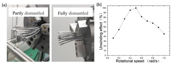
Figure 10.
(a) A comparative analysis of actual disentanglement performance under varying rotational speeds. (b) Quantification of the effect of rotational speed on disentanglement effectiveness.
During the disentanglement process, the study revealed that each single dismantling length of the conductor (defined as the distance between the conductor’s terminal end and the disentanglement device during operation) exerts a significant influence on disentanglement effectiveness. The relationship between the dismantling length and disentanglement performance is quantitatively demonstrated in Figure 11a. Experimental results indicate optimal disentanglement effectiveness at a protrusion length of approximately 10 cm, achieving near-complete separation of all aluminum wires in the target layer under this configuration. This critical parameter ensures maximum alignment stability and force transmission efficiency between the conductor and the disentanglement apparatus during the rotational process.
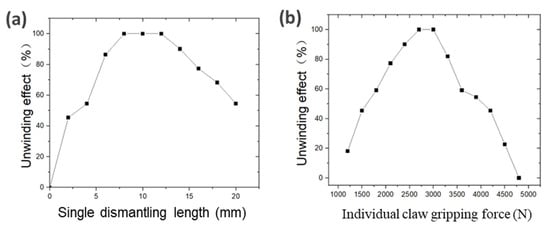
Figure 11.
(a) The influence of a single dismantling length on disentanglement efficiency. (b) The relationship between the chuck clamping force magnitude and disentanglement performance.
During the disentanglement process, the clamping force exerted by the three-jaw chuck must generate sufficient frictional force to resist the applied disentanglement torque and prevent conductor slippage. The frictional force provided by the chuck should satisfy the following requirement:
In the formula, denotes the critical torque required for disentangling the steel-reinforced aluminum conductor, and represents the radius of the conductor.
In the equation, μ represents the coefficient of friction between the aluminum conductor and the jaw material (where the jaw material is aluminum, μ = 0.2). The calculation yields a minimum required clamping force of 5000 N, corresponding to a minimum individual jaw clamping force of 1333 N per jaw. To investigate the influence of clamping force on practical disentanglement performance, this study conducted systematic experiments demonstrating that optimal disentanglement effectiveness is achieved when the individual jaw clamping force of the three-jaw chuck is approximately 2700 N, as illustrated in Figure 11b. This optimized clamping configuration ensures sufficient frictional resistance to torque transmission while mitigating mechanical deformation risks during the disentanglement process.
In addition to the aforementioned parameters, other process variables significantly influence disentanglement effectiveness. For instance, insufficient clamping force in the gripping device may induce a slippage phenomenon during rotation, severely compromising separation performance. Conversely, an excessive clamping force generates prohibitive compressive stress that not only hinders the conductor-layer separation but also causes substantial surface damage to the outer aluminum wires, adversely affecting subsequent inspection processes. This study systematically investigated the critical process parameters for torque-based disentanglement of steel-reinforced aluminum conductors, with the JL/G3A-500/65 conductor serving as the experimental prototype. The optimized operational parameters derived from empirical observations are summarized in Table 2.
Table 2.
Critical disentanglement process parameters.
Following the disentanglement procedure, the steel-reinforced aluminum conductor is transported via the conveyance module to the separation unit. Upon traversing the separation channel, the conductor is partitioned into disentangled and non-disentangled sections. Experimental observations revealed that improper disentanglement operations or mishandling during channel transit can induce overlapping and misalignment phenomena in partially separated aluminum wires, as illustrated in Figure 12a,b. Such irregularities significantly compromise subsequent shearing operations. Notably, this study demonstrates that a controlled rotational adjustment of the three-jaw chuck, as shown in Figure 12c, effectively mitigates wire misalignment by realigning the separated strands. Systematic experiments conducted with the parameters outlined in Table 3 confirmed that optimized chuck rotation substantially reduced overlapping defects in disentangled outer-layer aluminum wires. The quantitative analysis shown in Figure 12d indicates successful alignment correction for conductors featuring 22 outer-layer aluminum strands (typical of the JL/G3A-500/65 configuration), validating the operational efficacy of the proposed methodology.
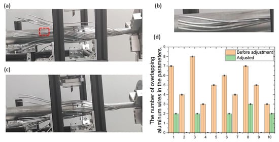
Figure 12.
(a) The overlapping phenomenon of multiple aluminum wires, (b) a magnified view of the overlapping region, (c) the reconfigured aluminum wire arrangement after rotational adjustment, and (d) a quantitative comparison of overlapping wire counts pre- and post-adjustment.
Table 3.
Critical shearing–separation process parameters.
Following alignment optimization, the outer-layer aluminum wires attain uniform spatial distribution, enabling precise shearing operations. The aluminum wires in this steel-reinforced conductor exhibit an approximate diameter of 3 mm, requiring a minimum severing force of 900 N as previously calculated. The system employs a pneumatic cylinder-actuated tungsten carbide cutting tool to execute wire severing. Upon completion of each cutting cycle, the chuck implements programmable stepwise rotational indexing with angular increments configurable between 5° and 360°. Through operator-supervised iterative cycles of directional shearing, complete layer separation is systematically achieved. This protocol ensures controlled material removal while maintaining the structural integrity of residual components, critical for preserving conductor geometry during sequential processing stages.
4. Conclusions
To address the challenges of a high operational complexity, intensive labor requirements, and inefficiency associated with the manual disassembly of steel-reinforced aluminum conductors, this study proposes a torque-based disassembly system. Firstly, mechanical feasibility analysis was conducted through finite element simulations, with results confirming the viability of a torque-driven layer separation. Subsequently, the system architecture was decomposed into three functionally optimized modules—conveyance, disentanglement, and shearing—through a systematic modular design methodology. Finally, the integration of sensor feedback mechanisms and coordinated power transmission subsystems established a synergistic mechatronic system. A comprehensive investigation of critical process parameters governing conductor disassembly was concurrently performed.
The torque-based disassembly system demonstrates significant advantages in labor efficiency and operational safety. Conventional manual disassembly necessitates skilled technicians and poses ergonomic risks from repetitive strain injuries. In contrast, the automated prototype developed in this study achieves standardized high-throughput disassembly through single-operator supervision, reducing labor intensity by 83% while ensuring consistent separation quality.
This research establishes a paradigm shift in conductor recycling through three key innovations: (1) validation of torque-based separation mechanics via aluminum–steel interfacial simulation modeling; (2) development of modular intelligent disassembly equipment overcoming traditional technological limitations; (3) achievement of aluminum recovery rates exceeding 98% with preserved material integrity. The system demonstrates substantial industrial scalability, enabling large-scale conductor disassembly integrated with inline quality inspection—a critical advancement for power grid maintenance and circular economy applications. A experimental verification confirmed a 72% efficiency improvement over manual methods (JL/G3A-500/65 specification). These technological breakthroughs position the system as a benchmark solution for sustainable conductor recycling infrastructure.
Author Contributions
Conceptualization, J.C. and J.H.; methodology, Z.C.; validation, J.F., S.X. and Q.P.; investigation, Z.C. and C.W.; data curation, J.C.; writing—original draft preparation, Z.C.; writing—review and editing, J.C. and J.H.; visualization, J.C.; supervision, J.C.; project administration, J.C. and J.F.; funding acquisition, J.F. All authors have read and agreed to the published version of the manuscript.
Funding
This work was supported by State Grid Sichuan Electric Power Company Technology Project (52199924001N).
Data Availability Statement
The raw data supporting the conclusions of this article will be made available by the authors on request.
Conflicts of Interest
Authors Zhinan Cao, Jie Feng and Shijun Xie were employed by the company Sichuan Shuneng Dianke Energy Technology Co., Ltd. The remaining authors declare that the research was conducted in the absence of any commercial or financial relationships that could be construed as a potential conflict of interest.
References
- You, C.Y. Research on the Application of Capacity-Expanded Conductors in Overhead Transmission Lines. Electr. Power Equip. 2006, 10, 1–7. [Google Scholar]
- You, C.Y. Research on the Application of Steel-Cored Soft Aluminum Stranded Wires in Overhead Transmission Lines. Electr. Power Constr. 2006, 27, 1–4+30. [Google Scholar]
- Milad, J.; Jordi-Roger, R.; Pooya, P. Aluminum Conductor Steel-Supported Conductors for the Sustainable Growth of Power Line Capacity: A Review and Discussion. Mater 2024, 17, 4536. [Google Scholar]
- Huang, X.C.; Chen, C.; Wang, F.; Zhao, Q.J.; Bai, X.L.; Wen, X.X. Study on Stress Distribution Characteristics of Aluminum Strands in Steel-Cored Aluminum Conductors for Long-Span Overhead Transmission Lines. J. China Three Gorges Univ. 2016, 38, 76–81. [Google Scholar]
- Zhang, X.S.; Niu, H.J.; Liu, S.C.; Yi, Q. Anti-vibration Measures of Ultrahigh Strength Steel Cored Aluminum Strand for Long-Span Overhead Line. Int. J. Front. Eng. Technol. 2022, 4, 10. [Google Scholar]
- Xie, Y.; Wang, S.D.; Zhang, C.; Ouyang, K.J.; Jiang, X.F. Study on Nondestructive Testing Methods for Crimping Quality of Steel Cored Aluminum Strand. IOP Conf. Ser. Earth Environ. Sci. 2019, 295, 032097. [Google Scholar] [CrossRef]
- Liu, F.; Findlay, R.D. Investigation of mechanical properties of single layer ACSR based on an Integrated Model. Electr. Power Syst. Res. 2007, 78, 209–216. [Google Scholar] [CrossRef]
- Hubei Jinyang Resources Co., Ltd. Disassembly and Separation Machine for Steel-Cored Aluminum Conductors. CN 207127482 U, 20 April 2018. [Google Scholar]
- Xinghua Senrong Metal Products Co., Ltd. Steel-Aluminum Wire Separation Device for Aluminum Conductor Recycling. CN 214107542 U, 22 June 2021. [Google Scholar]
- Gopalraj, S.K.; Kärki, T. A Study to Investigate the Mechanical Properties of Recycled Carbon Fibre/Glass Fibre-Reinforced Epoxy Composites Using a Novel Thermal Recycling Process. Processes 2020, 8, 954. [Google Scholar] [CrossRef]
- Ci, Y.Z. Research on Module Creation in Equipment Modular Design. Master’s Thesis, National University of Defense Technology, Changsha, China, 2004. [Google Scholar]
- Luo, G.F. Research and Application of Key Technologies in Manufacturing-Service-Oriented Modular Design of Complex Equipment. Zhengzhou Institute of Light Industry. 2017.
- Brunoe, T.D.; Daniel, G.; Soerensen, H.; Nielsen, K. Modular Design Methodology in Mechanical Engineering. Chem. Eng. Equip. 2020, 11, 183–184. [Google Scholar]
- Chen, X.J.; Yu, Y.; Xie, J.B. Modular Design Technologies and Applications for Complex Equipment. Equip. Manuf. Technol. 2024, 5, 118–120+136. [Google Scholar]
- Qi, Z.; Zhang, C.; Qiao, L.; Qin, J.; Wang, S. The Test Study on Tension-torsion Coupling Effect of ACSR in Overhead Transmission Lines. J. Phys. Conf. Ser. 2024, 2731, 012027. [Google Scholar] [CrossRef]
- Morgan, V.T. Research on Tension Layering Characteristics of Steel-Cored Aluminum Conductors for Overhead Lines. Electr. Wire Cable 2015, 4, 30–33. [Google Scholar]
- Yang, G.Y.; Wen, Z.M.; Gu, X.; Wu, M.Y.; You, W.R.; Xu, X. Research on Calculation Method of Strand Layer Stress in Steel-Cored Aluminum Conductors. Electr. Wire Cable 2023, 3, 40–45. [Google Scholar]
- Zhang, L.; Huang, J.; Zhong, Y.L.; Yan, Z.T. Tension, Torsion Coupling Mechanical Properties of Steel-Cored Aluminum Conductors. J. Southwest Jiaotong Univ. 2021, 56, 889–896+904. [Google Scholar]
- Wu, J.G.; Xu, H.H.; Liu, S.S.; Zhou, X.K. Design and Development of Tensile Numerical Simulation System for Steel-Cored Aluminum Conductors. Electr. Power Equip. Manag. 2020, 11, 166–168. [Google Scholar]
- Yu, J.; Wu, C.; Huang, H.; Xie, D.; Qin, F.; Jiang, J.; He, G. Discussion on AC Resistance and Temperature of ACSR Based on Finite Element Model Assistance. Energies 2025, 18, 539. [Google Scholar] [CrossRef]
- IEC 61089; Round Wire Concentric Lay Overhead Electrical Stranded Conductors. International Electrotechnical Commission (IEC): Geneva, Switzerland, 1991.
- ASTM B232/B232M; Standard Specification for Concentric-Lay-Stranded Aluminum Conductors, Coated-Steel Reinforced (ACSR). ASTM International: West Conshohocken, PA, USA, 2023.
Disclaimer/Publisher’s Note: The statements, opinions and data contained in all publications are solely those of the individual author(s) and contributor(s) and not of MDPI and/or the editor(s). MDPI and/or the editor(s) disclaim responsibility for any injury to people or property resulting from any ideas, methods, instructions or products referred to in the content. |
© 2025 by the authors. Licensee MDPI, Basel, Switzerland. This article is an open access article distributed under the terms and conditions of the Creative Commons Attribution (CC BY) license (https://creativecommons.org/licenses/by/4.0/).