Abstract
Traditional three-row roller YRT turntable bearings exhibit high friction torque during operation, which limits their performance in high-precision and high-response applications. To address this issue, a novel ball–roller composite turntable bearing is proposed that effectively reduces friction torque while maintaining a high load capacity. A mechanical model based on statics is established, and the Newton–Raphson method is employed to calculate the contact load. The formation mechanism of friction torque is analyzed, and a corresponding computational model is developed and validated using experimental data. The effects of axial load, eccentricity, overturning moment, rotational speed, and axial clearance on friction torque are systematically studied. Results indicate that friction torque increases with these parameters. Axial clearance has a significant influence, and an optimal clearance value between the balls and rollers is determined. Additionally, a reasonable range for the raceway curvature radius coefficient is proposed. When the numerical ratio of balls to rollers is 1, the bearing exhibits optimal friction performance. Among various roller crowning strategies, logarithmic crowning yields the best results. This study provides a theoretical basis and technical support for the optimized design of ball–roller composite turntable bearings.
1. Introduction
Turntable bearings are extensively utilized in aerospace, radar, satellite communications, and other domains that demand high precision, reliability, and substantial load support. Traditional three-row cylindrical roller YRT turntable bearings often experience excessive friction torque, resulting in increased energy consumption and significant heat generation during operation. This phenomenon can lead to lubrication failure and thermal deformation, which adversely impacts rotational accuracy. Furthermore, elevated friction accelerates wear between the rolling elements and raceways, thereby reducing the service life of the bearings and compromising the dynamic response and positioning accuracy of the system. Such degradation is particularly detrimental to high-precision and high-efficiency machining applications. Consequently, minimizing friction torque is essential for enhancing bearing performance.
A substantial body of research has been conducted by both domestic and international scholars on the friction torque characteristics of rolling bearings. Palmgren et al. [1] performed extensive friction torque tests on bearings and derived empirical formulas under various conditions. Their study indicated that, under low-speed and heavy-load conditions, load-dependent friction dominates, whereas, under high-speed and light-load conditions, viscous resistance is the primary contributor. Chiu et al. [2], based on experimental data, proposed empirical calculation formulas for the friction torque of thrust needle roller bearings. Their results established reference and permissible speeds for bearings based on experimentally derived power loss formulas. Ghanbari et al. [3] investigated the variation patterns of friction torque in ball bearings under different working conditions, clarifying the effects of bearing speed and applied load on friction torque. Li et al. [4] proposed an improved method for calculating the friction torque of tapered roller bearings. This method simulates sliding friction coefficients under various lubrication states, effectively overcoming the limitations of traditional empirical formulas that neglect lubrication conditions and combined load effects. Ye et al. [5] experimentally analyzed the influences of environmental pressure, mounting method, and rotational speed on bearing friction torque. The study revealed that friction torque reaches its maximum under vacuum conditions with horizontal mounting, and that speed significantly affects friction characteristics. Fernandes et al. [6] tested friction torque in thrust ball bearings using different gear oils, analyzing the effects of oil viscosity, additives, and operating conditions. Their results demonstrated that synthetic oils exhibit superior friction stability compared to mineral oils, and that extreme pressure additives effectively reduce friction. Hammami et al. [7] employed an enhanced four-ball tester to evaluate the effects of speed, temperature, and axial load on the friction torque of rolling bearings. Zhang et al. [8] analyzed the mechanisms of friction generation in ball bearings, focusing on the interactions and motion states among the internal bearing components. They developed an accurate model for calculating friction torque and suggested that when direct calculations are challenging, energy methods can be utilized to back-calculate friction torque. Deng et al. [9,10] formulated friction torque calculation models for thrust ball bearings and thrust needle roller bearings based on bearing dynamics. Their research examined the impact of various structural parameters and operational conditions on friction torque. The results indicated that 70% of the total friction torque in thrust ball bearings originates from the spin-slip of steel balls, with fully convex circular arc ground needles proving to be more effective in reducing bearing friction torque. Goncz et al. [11] established a mechanical analysis model for three-row cylindrical roller bearings employing vector description and coordinate transformation methods. Their investigation underscored the sensitivity of bearing contact stress to clearance parameters, particularly under boundary load conditions. Zupan [12] and Amasorrain et al. [13] developed load analysis models for single-row four-point contact slewing bearings, examining the effects of geometric parameters on contact stress distribution. Chen et al. [14] explored the impact of negative clearance on bearing contact stress, demonstrating a positive correlation between clearance and contact stress. Deng et al. [15] utilized ABAQUS to construct finite element slice models of slewing bearing rolling elements and raceways, analyzing the contact stress distribution under varying load conditions for different raceway geometries. Their findings revealed that, in comparison to two-point contact slewing bearings, four-point contact slewing bearings demonstrate a more uniform contact stress distribution between rolling elements and raceways. Krynke [16] and Zhang et al. [17] examined the impact of clearance and groove curvature coefficient on load distribution and maximum contact stress in slewing bearings. Their research indicated that zero clearance enhances the static load capacity of slewing bearings, while the maximum contact stress decreases with a reduction in the groove curvature coefficient. Peter G. et al. [18] and Ju S et al. [19] investigated the effects of roller structural parameters with varying crowning methods on roller load capacity and contact area load distribution. Wang et al. [20] calculated bearing friction torque and compared the torque ratios between single-row and double-row ball bearings using finite element analysis, corroborating the results with experimental data. Wang et al. [21] conducted comparative studies on friction torque between rolling elements and raceways in four-point contact ball slewing bearings and crossed roller slewing bearings under axial load. Gärtner et al. [22] proposed a novel, simple, and cost-effective method to measure friction torque in spindle bearings, examining the effects of oil, air, and grease lubrication on bearing friction torque. Yang et al. [23] established a numerical calculation model for friction torque in double-row four-point contact ball bearings based on static analysis, investigating the influence of load and geometric parameters on friction torque. Li et al. [24] developed a friction torque calculation model for three-row cylindrical roller wind turbine main shaft bearings under combined loads, analyzing the effects of axial clearance, roller quantity, and other parameters on friction torque. Zhang et al. [25] established a friction torque calculation model for YRT slewing bearings based on static theory, analyzing the influence of operating conditions, axial clearance, and roller crowning on friction torque, with experimental validation of the model. Furthermore, Zhang et al. [26] developed a friction torque calculation model for combined ball and cylindrical roller slewing bearings, revealing that a lower friction torque can be achieved while ensuring bearing load capacity when the groove curvature radius coefficient is between 0.57 and 0.58.
Although replacing all axial rollers in conventional YRT turntable bearings with steel balls can significantly reduce friction torque, it also leads to a noticeable decrease in axial stiffness. To achieve a balance between low friction and high load-carrying performance, this paper proposes a novel ball–roller composite turntable bearing structure, wherein some rollers are substituted with steel balls. This design effectively integrates the high stiffness characteristics of roller bearings with the low friction advantages of ball bearings, showcasing promising potential for engineering applications. Nevertheless, current research by both domestic and international scholars has predominantly concentrated on the friction torque characteristics of single-type bearings, either roller or ball. Investigations into hybrid configurations that combine rollers and balls remain scarce, particularly concerning the impact of parameter matching between rollers and balls on friction torque. For the newly proposed ball–roller composite turntable bearing, there is still a lack of systematic theoretical analysis and calculation models pertaining to its friction torque characteristics. This gap results in insufficient theoretical support for practical design. Therefore, it is imperative to conduct in-depth investigations to enhance the optimized design and engineering application of such bearings.
This study established a friction torque calculation model for the novel ball–roller composite turntable bearing based on static mechanical theory. The influence of key parameters, including axial load, load eccentricity, overturning moment, ball-to-roller numerical ratio, axial clearance, ball raceway curvature radius coefficient, bearing rotational speed, and roller crowning method, on the friction torque is systematically investigated. The research findings offer theoretical support and design guidelines for the structural optimization and engineering application of ball–roller composite turntable bearings.
2. Relevant Fundamental Theories
To accurately establish the static mechanical model of the novel ball–roller composite turntable bearing and effectively analyze load distribution and friction torque, it is essential to first present the fundamental kinematic principles of rolling bearings, the characteristics of contact load distribution, and the theoretical basis of the slice method. This section on fundamental theory lays a solid theoretical foundation for the analytical models, computational methods, and simplifying assumptions proposed in the subsequent study.
2.1. Kinematic Characteristics of Rolling Elements
During operation, rolling elements in a rolling bearing exhibit both revolution and rotation. Their motion behavior significantly influences the distribution of contact loads and friction characteristics. Under ideal conditions, rolling elements should engage in pure rolling between raceways, meaning there should be no sliding or additional deformation. However, in practical applications, factors such as asymmetric loading, assembly errors, and material elastic deformation often result in sliding, additional tilting, and localized relative displacements of the rolling elements. These phenomena lead to more complex contact conditions and increased localized friction. This complexity is particularly pronounced in ball–roller composite bearings, where the motion behaviors of balls and rollers differ. Balls form point contacts and possess greater degrees of freedom, while rollers have wider contact zones but are more susceptible to axial tilting and edge contact effects. Therefore, accurately modeling the motion of rolling elements is crucial for precise calculations of load transmission and friction torque.
2.2. Contact Load and Distribution Characteristics
The contact state between the rolling elements and raceways is non-ideal, resulting in non-uniform and nonlinear load distribution among the individual rolling elements within a bearing. Rolling elements positioned near the principal load direction experience the highest loads, while those on either side undergo a rapid decrease in load and may even lose contact entirely. This phenomenon is particularly pronounced in large turntable bearings, significantly affecting both friction performance and load-carrying capacity. The contact behavior between rolling elements and raceways can be analyzed using Hertz contact theory. According to this theory, under elastic contact conditions, the normal load between two contacting bodies exhibits a power-law relationship with the contact deformation, influenced by factors such as material elastic modulus, contact curvature, and initial clearance. The Hertz framework can effectively model both point contact between balls and raceways as well as line contact between rollers and raceways, to characterize contact deformation behavior.
2.3. Fundamental Principles of the Slice Method
To enhance the accuracy of contact load calculations, particularly in analyzing the contact behavior of line-contact elements such as cylindrical rollers, this study employs the slice method for modeling and analysis. The slice method is an analytical approach that utilizes numerical integration and segmented computation, and it is widely applied in the mechanical analysis of rolling bearings. This method entails dividing the raceway contact surface of the bearing into several thin slices along either the axial or radial direction. The local contact load and deformation of each slice are calculated individually, and the overall load response of the rolling element is subsequently obtained by summing the results of all slices. The fundamental concept of the slice method is to transform a complex three-dimensional contact problem into multiple two-dimensional approximate problems, thereby significantly reducing the complexity of mathematical modeling and computation.
The slice method was not proposed by a single researcher; rather, its mathematical concept originates from Palmgren’s early 20th-century analysis of rolling element load distribution. In the 1960s and 1970s, this method was further developed into a structured segmented numerical analysis technique by researchers such as Harris, becoming widely applied in the contact mechanics modeling of cylindrical roller bearings. Due to its versatility and practicality, the method has undergone continuous refinement in subsequent studies, establishing it as one of the classical approaches in rolling bearing analysis.
3. Static Model of the Novel Ball–Roller Composite Turntable Bearing
3.1. Bearing Structure
The novel ball–roller composite turntable bearing comprises three rows of rolling elements, along with an outer ring, Inner Ring No. 1, Inner Ring No. 2, and Inner Ring No. 3, as illustrated in Figure 1.
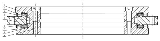
Figure 1.
Schematic diagram of the structure of the novel ball–roller composite turntable bearing. 1—First inner ring; 2—Axial rollers; 3—Cage; 4—Radial rollers; 5—Outer ring; 6—Axial steel ball; 7—Third inner ring; 8—Second inner ring; 9—Connecting bolt.
In the axial direction, both the upper and lower rows of rolling elements consist of one row of cylindrical rollers and one row of steel balls arranged in an alternating pattern, with rollers positioned on the outer side and steel balls on the inner side. Cages are installed between the rolling elements to ensure proper separation. The schematic diagram of the cage structure is illustrated in Figure 2. The radial row of cylindrical rollers is fully loaded. The first, second, and third inner rings are interconnected by bolts, forming the bearing’s inner ring. During operation, the outer ring of the bearing is fixed to the base, while the inner ring rotates.
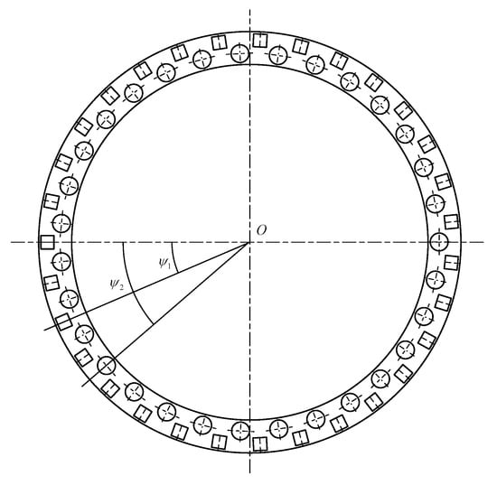
Figure 2.
Schematic diagram of the cage.
3.2. Static Modeling and Reasonable Assumptions
In the static analysis, three reasonable assumptions are made to simplify the modeling process and enhance computational efficiency.
Initially, the influence of the connecting bolts is neglected. This decision stems from the fact that the stiffness of the bolts is significantly higher than the internal contact stiffness of the bearing, making their deformation and stress have minimal impact on the overall mechanical response. Incorporating the bolts into the analysis would not only complicate the model but also substantially increase computational costs. Consequently, this simplification is justified, as it does not compromise the accuracy of the analysis.
Second, the inner ring of the bearing is treated as a rigid body. Although the inner ring may consist of multiple components, due to the tight structural connection and negligible relative displacement between parts, it can be reasonably approximated as a single rigid body. This assumption effectively reduces the system’s degrees of freedom and simplifies the formulation and solution of the equilibrium equations.
Finally, it is assumed that the outer ring is fixed while the inner ring rotates. This assumption is based on the structural characteristics of the experimental setup: during testing, the inner ring is connected to the motorized spindle via a coupling flange, while the outer ring is attached to a stationary force sensor through a mounting base. Therefore, under the test conditions, the bearing operates with a rotating inner ring and a stationary outer ring.
These assumptions simplify the model without compromising the analysis of key mechanical behaviors, thereby improving computational efficiency.
As illustrated in Figure 3, the inner ring of the bearing experiences axial displacement (δa), radial displacement (δr), and a rotation angle (θ) due to the combined effects of axial force (Fa), radial force (Fr), and overturning moment (M). In the figure, ψ1 denotes the position angle of the axial row of rollers, ψ2 indicates the position angle of the axial row of balls, dm1 represents the pitch circle diameter of the axial rollers, dm2 signifies the pitch circle diameter of the axial balls, and dmr refers to the pitch circle diameter of the radial rollers.
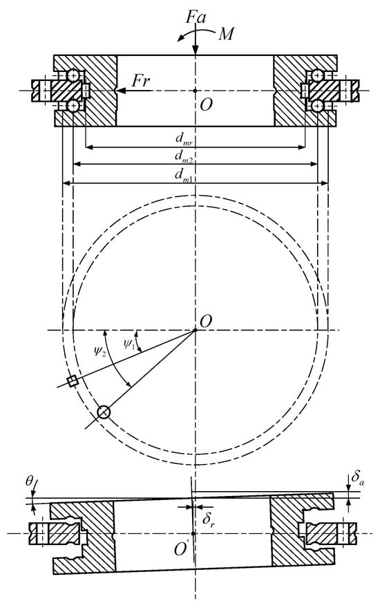
Figure 3.
Relative displacement between inner and outer rings under combined loading.
3.3. Force Analysis
The primary objective of force analysis is to accurately determine the contact loads and their distribution between the rolling elements and raceways. This analysis provides essential data for the precise calculation of friction torque.
The contact between the axial steel balls and the bearing rings is characterized by point contact. In contrast, the interaction between the axial cylindrical rollers, radial cylindrical rollers, and the raceways does not exhibit ideal linear contact. Consequently, the slice method is employed to calculate the contact load between the rollers and the raceways.
For ease of calculation, each cylindrical roller in the bearing is divided into n equal slices, and the force diagram of the i-th cylindrical roller slice is illustrated in Figure 4.
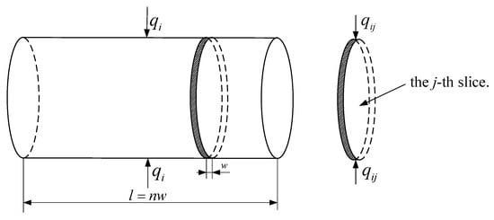
Figure 4.
Schematic diagram of the force on the i-th roller slice.
Then, the thickness of each slice for the axial cylindrical rollers and radial cylindrical rollers is as follows:
In the formula, l1 and l2 are the effective lengths of the axial cylindrical rollers and radial cylindrical rollers, respectively.
3.3.1. Contact Load Analysis Between Axial Cylindrical Rollers and Raceways
Under the combined loading conditions, the normal approach between the raceway surfaces at the center of the j-th slice of the i-th roller in the upper axial row can be expressed as follows [27]:
In the formula, the superscript u represents the upper row of axial rollers; ψ1i is the position angle of the j-th roller, and at the point of maximum deformation ψ1i = 0, Z1 is the number of rollers per axial row; ua01 is the initial axial clearance of the rollers; is the convexity drop at the center of the j-th slice of the i-th roller in the upper axial row.
The normal approach between the raceway surfaces at the center of the j-th slice of the i-th roller in the lower axial row is defined as follows:
In the formula, the superscript d represents the lower row of axial rollers.
The normal load borne by each slice of the roller is as follows [27]:
In the formula, A = 1.36η0.3, η represents the combined elastic modulus of the two contacting bodies.
Then, the normal load borne by each cylindrical roller in the axial direction is as follows:
3.3.2. Contact Load Analysis Between Axial Steel Balls and Raceways
Under the combined load, the normal approach between the two raceway surfaces for the i-th steel ball in the upper axial row can be expressed as follows [26]:
In the formula, the superscript u refers to the upper row of axial balls; Z2 is the number of steel balls per axial row; ψ2i is the position angle of the steel ball in the upper axial row; ua02 is the initial axial steel ball clearance.
Under the combined load, the normal approach between the two raceway surfaces for the i-th steel ball in the lower axial row can be expressed as follows:
In the formula, the superscript d refers to the lower row of axial balls.
According to Hertz contact theory, the contact load on each steel ball is expressed as follows:
In the formula, Kn represents the total load-deformation constant between the steel ball and the inner and outer rings.
3.3.3. Contact Load Analysis Between Radial Cylindrical Rollers and Raceways
Under the combined load, the normal approach between the two raceway surfaces at the center of the j-th slice of the i-th roller in the radial row can be expressed as follows [27]:
In the formula, the superscript m represents the radial row of rollers; ψ3i is the position angle of the i-th roller; ur0 is the initial radial clearance of the rollers; is the convexity drop at the center of the j-th slice of the i-th roller in the radial row.
The normal load borne by each slice of the radial cylindrical roller is as follows:
Then, the normal load borne by each radial cylindrical roller is as follows:
3.4. Mechanical Equilibrium Equations of the Bearing Inner Ring and Numerical Solution
To determine the contact loads of the rollers and balls in each row of the bearing, it is necessary to establish the force and moment equilibrium equations for the inner ring of the bearing. The inner ring of the bearing is in equilibrium under the combined action of the axial force Fa, radial force Fr, overturning moment M, and the contact forces between the rolling elements and the raceways. The following equilibrium equations can be derived sequentially.
The axial equilibrium equation for the bearing inner ring is expressed as follows:
The radial equilibrium equation for the bearing inner ring is expressed as follows:
The moment equilibrium equation for the bearing inner ring is expressed as follows:
By combining the above equations and substituting the parameters of the novel ball–roller composite turntable bearing, the equilibrium equations of the bearing inner ring are solved using the Newton–Raphson iterative method. The Newton–Raphson method is implemented primarily with MATLAB 2023b software. Under combined loading conditions, the axial displacement (δa), radial displacement (δr), and deflection angle (θ) of the inner ring are obtained, based on which the loads borne by each rolling element can be further calculated. The computational flowchart is shown in Figure 5.
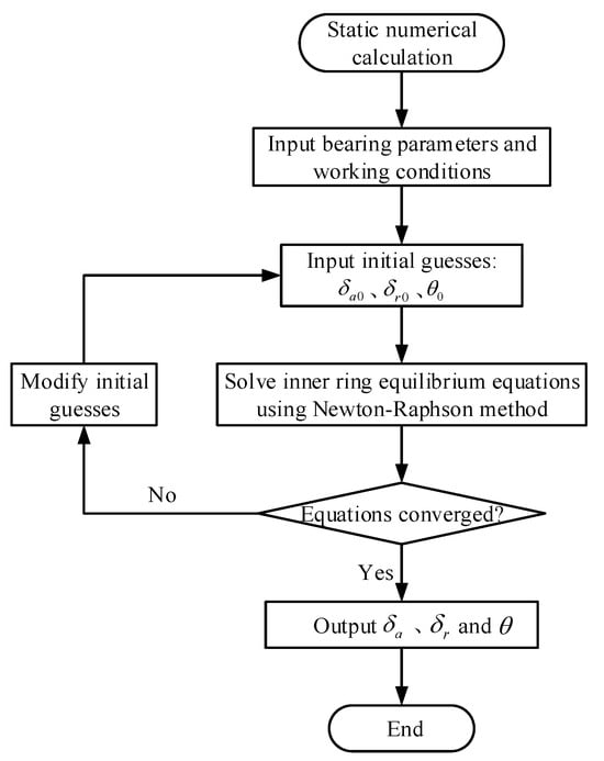
Figure 5.
Static mechanical calculation flowchart of the bearing.
3.5. Kinematic Analysis
Based on the relevant knowledge of bearing kinematics [27], we can derive the kinematic equations applicable to the structure of the novel ball–roller composite turntable bearing studied in this paper.
As illustrated in Figure 6, the X-axis represents the geometric centerline of the bearing in the horizontal direction, while the Y-axis indicates the geometric centerline of the bearing in the vertical direction. Point O denotes the geometric center of the bearing. The distance from the midpoint of the axial roller’s generatrix to the Y-axis is 0.5dm1, the distance from the center of the axial ball to the Y-axis is 0.5dm2, and the distance from the centerline of the radial roller to the Y-axis is 0.5dmr. The diameters of the axial rollers, axial balls, and radial rollers are denoted as D1, D2, and D3, respectively.
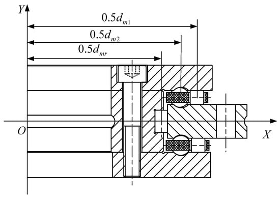
Figure 6.
Schematic diagram of bearing rolling element geometry and motion parameters.
The angular velocity of the inner ring is denoted as ωi, the angular velocity of the outer ring as ωo, the orbital angular velocity of the rollers as ωc, and the spin angular velocity of the rollers as ωr. The distance from the center of the j-th slice of the i-th cylindrical roller in the axial row to the bearing center is represented as yij. Additionally, ωb denotes the orbital angular velocity of the axial steel balls, while signifies the spin angular velocity of the axial steel balls.
Due to the low operating speed of the novel ball–roller composite turntable bearing, the relative motion between the rollers and steel balls in the axial row, as well as the raceway at the pitch circle position, can be considered as pure rolling. Based on the no-slip condition, the self-rotation and orbital angular velocities of the axial row rollers can be derived as follows:
Due to the varying linear velocities at different points along the contact line between the axial cylindrical rollers and the raceways, relative sliding must occur on both sides of the pitch circle within the contact area. The relative sliding velocity between the j-th slice of the i-th roller in the axial row and the inner or outer ring raceways is as follows:
In the formula, the subscripts in and o represent the inner ring and outer ring of the bearing, respectively.
The average velocities of the i-th axial roller at the pitch circle relative to the inner and outer raceways are expressed as follows:
The orbital angular velocity and spin angular velocity of the i-th axial ball are ex-pressed as follows:
Therefore, the average linear velocities of the i-th axial ball at the pitch circle relative to the inner and outer raceways are expressed as follows:
Since the linear velocities at all points on the contact line between the radial cylindrical rollers and the raceways are equal, it can be concluded that there is no relative sliding between the cylindrical rollers and the raceways. Based on the no-slip condition, the expressions for the spin angular velocity and the orbital angular velocity of the radial cylindrical rollers can be derived as follows:
The average velocity between the i-th cylindrical roller in the radial row and the inner/outer raceways is as follows:
4. Calculation of Bearing Friction Torque
To accurately evaluate the friction performance of the novel ball–roller composite turntable bearing during operation, this study establishes a component-wise calculation model that incorporates multiple friction sources based on a thorough analysis of friction mechanisms. Based on the principle of energy conservation, various forms of energy loss are uniformly transformed into friction torque. The total friction torque of the bearing comprises five main components: (1) the friction torque arising from the elastic hysteresis of cylindrical rollers and steel balls, (2) the friction torque resulting from the differential sliding of axial cylindrical rollers, (3) the friction torque generated by the viscous friction of cylindrical rollers and steel balls, (4) the friction torque caused by the spin sliding of axial steel balls, and (5) the friction torque produced by the sliding friction between the cage and the guide surface.
The component models presented herein are numerically implemented using MATLAB programming, incorporating a parameterized input scheme to accommodate various bearing operating conditions. The calculation of each friction torque is based on input variables, including bearing structural parameters, load distribution, lubrication conditions, and material properties. These variables are processed by integrating existing theoretical models with empirical formulas. The total friction torque of the bearing is derived by summing these individual components, which serves as the foundation for subsequent friction characteristic analysis and structural optimization design.
4.1. Friction Torque Caused by Elastic Hysteresis of Cylindrical Rollers and Steel Balls
When cylindrical rollers or steel balls roll on the raceway, the elastic hysteresis of the material results in an asymmetric pressure distribution across the contact area. The resistance moment exerted by the pressure on the front half of the contact surface is greater than the driving moment exerted by the pressure on the rear half, leading to the generation of friction torque.
- (1)
- Friction torque generated by elastic hysteresis of cylindrical rollers.
The energy loss caused by material elastic hysteresis between the raceways of axial cylindrical rollers is as follows [10]:
The energy loss caused by material elastic hysteresis between the raceways of radial cylindrical rollers is as follows:
In the formula, ξ represents the material hysteresis coefficient; for bearing steel it can be taken as ξ = 0.01.
According to the law of conservation of energy, the friction torque caused by the elastic hysteresis of the rollers is as follows:
- (2)
- Friction torque caused by elastic hysteresis of steel balls [5].
In the formula, α0 represents the contact angle of the steel ball, which in this case is 90°; β represents the material hysteresis coefficient, and for this study, it is taken as 0.007.
The calculation formula for φi(o) is expressed as follows:
In the formula, a and b represent the lengths of the major and minor semi-axes of the elliptical contact area between the steel ball and the raceway, respectively; na(b) is a coefficient related to the difference in principal curvatures at the contact point with the steel ball; Ek(e) denotes the first and second kinds of elliptic integrals, respectively; μ1(2) represents the Poisson’s ratios for the steel ball and the raceway material, respectively; Qu(d) is the contact load on the steel ball.
Therefore, the friction torque caused by elastic hysteresis of cylindrical rollers and steel balls is as follows:
4.2. Friction Torque Caused by Differential Sliding of Cylindrical Rollers
The linear velocities at the contact points between the axial row rollers and the raceway are not entirely consistent, resulting in differential sliding between the rollers and the raceway surface, which generates sliding friction. In contrast, the linear velocities at the contact points between the radial row rollers and the raceway are uniform, allowing for the assumption that no differential sliding occurs with the radial rollers.
The energy loss resulting from the relative sliding between the axial cylindrical rollers and the raceways is detailed as follows [28]:
In the formula, uij represents the oil film traction coefficient, which is obtained by interpolating the elasto-hydrodynamic (EHD) traction coefficient and the boundary lubrication friction coefficient through the oil film parameters [29,30].
According to the law of conservation of energy, the friction torque resulting from the differential sliding of axial cylindrical rollers can be expressed as follows:
4.3. Friction Torque Caused by Viscous Friction of Rollers and Steel Balls
- (1)
- The friction torque of the roller due to the viscosity of the lubricant.
The energy loss due to the viscous resistance of the grease between the cylindrical rollers and the raceways of the bearing is outlined as follows [31]:
In the formula, E0 represents the equivalent elastic modulus between the roller and the raceway; R0 denotes the equivalent radius of curvature; U is the velocity parameter between the roller and the inner and outer rings; G is the material parameter between the roller and the inner/outer rings; W is the load parameter between the roller and the inner/outer rings.
The calculation methods for U, G, and W are as follows:
In the formula, η0 is the dynamic viscosity of the grease; α′ is the pressure–viscosity coefficient of the grease.
According to the law of conservation of energy, the friction torque exerted on cylindrical rollers due to the viscosity of grease can be expressed as follows:
- (2)
- The friction torque generated by the viscosity of the lubricating grease on the axial steel balls.
During the movement of steel balls, the grease exerts a specific resistance on the steel balls, which further generates friction torque. The friction torque resulting from the viscous resistance of axial steel balls is expressed as follows [8]:
In the formula, Hin(o) denotes the oil film thicknesses between the steel ball and the inner and outer rings, respectively, and S is the oil film lubrication coefficient.
Therefore, the friction torques caused by viscous friction of cylindrical rollers and steel balls are as follows:
4.4. Friction Torque Due to Spinning and Sliding of Axial Steel Balls
The axial row steel balls exhibit a contact angle of 90°, which induces a spinning motion during rotation. The friction torque produced by the self-spinning and sliding of the steel balls can be expressed as follows [4]:
4.5. Friction Torque Due to Sliding Friction Between Retainer and Guide Surface
During the operation of the bearing, the two axial retainers maintain contact with the guide surfaces and experience sliding friction. Consequently, the torque generated due to sliding friction can be expressed as follows [26]:
In the formula, Wg represents the mass of the retainer; fc denotes the coefficient of friction between the retainer and the guide surface.
4.6. Total Friction Torque of the Bearing
By summing all individual friction torque components generated during the operation of the novel ball–roller composite turntable bearing, the total friction torque experienced by the bearing can be determined. The total friction torque of the bearing is expressed as follows:
5. Experimental Verification of Bearing Friction Torque
5.1. Friction Torque Testing
To validate the friction torque model discussed in this paper, modifications were made to the existing bearing friction torque testing equipment to accommodate the specific loading requirements of the novel ball–roller composite turntable bearing. A schematic diagram illustrating the main structure of the friction torque testing machine is presented in Figure 7.
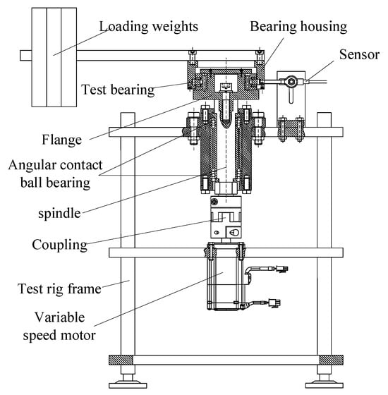
Figure 7.
Schematic diagram of the friction torque testing machine structure.
The physical diagram of the test bearing is shown in Figure 8.
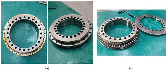
Figure 8.
(a) Image of the novel ball–roller composite turntable bearing. (b) Image of the conventional three-row cylindrical roller turntable bearing.
The inner ring of the tested bearing is installed on a flange plate, which is connected to the main shaft by bolts. The outer ring is fitted with the bearing housing, and the load is applied to the loading plate. When measuring the friction torque, the motor drives the inner ring of the novel ball–roller composite turntable bearing to rotate through the main shaft. The frictional force generated by the bearing is input into the control system via a force sensor fixed on the machine frame. Finally, the bearing friction torque is calculated by the system software and displayed on the monitor. The physical diagram of the friction torque testing machine is shown in Figure 9.
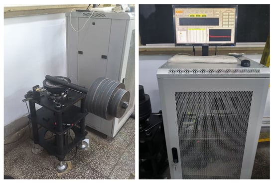
Figure 9.
Physical image of the friction torque testing machine.
5.2. Test Bearing-Related Parameters
The tested bearing is a novel type of ball–roller composite turntable bearing, with its dimensional and structural parameters detailed in Table 1.

Table 1.
Parameters of the novel ball–roller composite turntable bearing.
5.3. Analysis of Test Results
5.3.1. Comparative Analysis of Experimental Results Between the Novel and Conventional Bearings
To verify the friction performance advantages of the novel ball–roller composite turntable bearing, a comparative experiment was conducted against a conventional turntable bearing. The selected reference bearing is a typical traditional YRT turntable bearing, which shares identical dimensional specifications and test conditions with the novel bearing, thereby ensuring the validity of the comparison.
In the friction torque tests, the outer ring of the bearing was fixed while the inner ring was rotated. For both types of bearings, the rotational speed was maintained at 5 r/min, and the axial load was incrementally increased from 0 kN to 6 kN. The experimental results for both bearing types are presented in Figure 10.
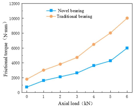
Figure 10.
Variation of friction torque with axial load for the two types of bearings.
As demonstrated in Figure 10, the friction torque of both the novel ball–roller composite turntable bearing and the conventional three-row cylindrical roller turntable bearing increases with the axial load. However, under identical load conditions, the friction torque of the novel bearing is significantly lower than that of the conventional bearing. This finding indicates that the novel ball–roller composite turntable bearing exhibits superior friction performance.
5.3.2. Experimental Results Analysis of the Novel Ball–Roller Composite Turntable Bearing
In the bearing friction torque test, the outer ring of the bearing is fixed while the inner ring rotates. The friction torque is measured under various working conditions, including rotational speed, axial load, and overturning moment. The experimental results are then compared with the theoretical analysis outcomes to evaluate their consistency.
- (1)
- Test results of bearing friction torque under different rotational speeds.
When the axial roller clearance of the novel ball–roller composite turntable bearing is 0 μm, the axial steel ball clearance is −2 μm, and the axial load is 2 kN, the rotational speed is incrementally increased from 5 r/min to 90 r/min. The test values and theoretical analysis values of the friction torque for the novel ball–roller composite turntable bearing are presented in Figure 11.
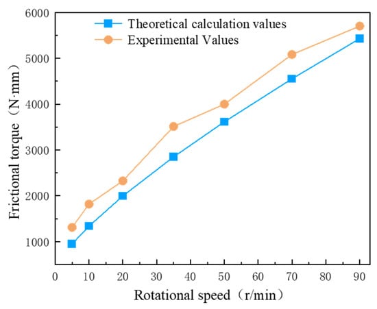
Figure 11.
Influence of rotational speed on bearing friction torque.
Figure 11 illustrates that the variation trend of the test values and theoretical calculation values of the bearing friction torque is largely consistent with changes in rotational speed. Notably, the average error between the test values and theoretical values of the bearing friction torque across different rotational speeds is 15.97%.
- (2)
- Test results of bearing friction torque under different axial loads.
When the axial roller clearance of the novel ball–roller composite turntable bearing is 0 μm, the axial steel ball clearance is −2 μm, and the rotational speed is 5 r/min, the axial load increases from 0 kN to 8 kN. The friction torque values obtained from tests, along with those derived from theoretical analysis, are illustrated in Figure 12.
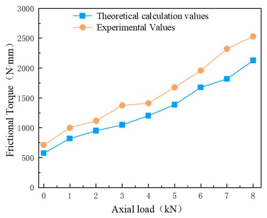
Figure 12.
Influence of axial load on bearing friction torque.
Figure 12 illustrates that the variation trend of the test values and theoretical calculation values of the bearing friction torque is largely consistent with changes in axial load. Under varying axial loads, the average error between the test values and theoretical values of the bearing friction torque is found to be 17.84%.
- (3)
- Test results of bearing friction torque under different overturning moments.
When the axial clearance of the roller row in the novel ball–roller composite turntable bearing is 0 μm, and the axial clearance of the ball row is −2 μm, with a rotational speed of 5 r/min, the overturning moment load increases from 0 N·m to 400 N·m. The experimental and theoretical analysis values of the friction torque for the novel ball–roller composite turntable bearing are depicted in Figure 13.
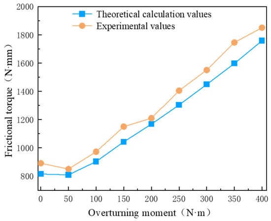
Figure 13.
Influence of overturning moment on bearing friction torque.
Figure 13 illustrates that as the overturning moment load changes, the trends of the test values and theoretical calculation values of the bearing friction torque are largely consistent. Under varying overturning moment loads, the average error between the test and theoretical values of the bearing friction torque is 12.70%.
Based on the analysis of Figure 8, Figure 9 and Figure 10, it can be concluded that the variation trends of the test values and theoretical analysis values for the friction torque of the novel ball–roller composite turntable bearing are consistently aligned. The discrepancies between the test values and theoretical analysis values are attributed to two main factors: the friction between the rolling elements and the cage pocket holes was not considered in the theoretical model, and installation errors of the bearing during the test may have occurred. However, these deviations fall within an acceptable error range. Therefore, the friction torque calculation model established in this paper for the novel ball–roller composite turntable bearing is deemed reasonable. This model can provide theoretical support for the subsequent analysis of the friction torque characteristics of novel ball–roller composite turntable bearings.
6. Analysis of Friction Torque Characteristics for Novel Ball–Roller Composite Turntable Bearings
To gain a deeper understanding of the friction behavior of the novel ball–roller composite turntable bearing under typical assembly and loading conditions, a systematic parametric analysis and numerical simulation study is conducted based on the previously established friction torque model. This chapter investigates the mechanisms influencing the structural parameters and working conditions on the bearing’s friction torque by integrating single-factor analysis with an orthogonal design approach.
Initially, the single-factor method is employed to assess the primary effects of key variables, including axial clearance, the coefficient of curvature radius of the ball groove, the position of load application, the ratio of rolling elements, and the roller crowning method. Subsequently, an orthogonal design based on numerical modeling is established to conduct a multi-parameter coupling analysis on four significant influencing factors: axial roller clearance, axial ball clearance, the coefficient of curvature radius of the ball groove, and the position of load application. This analysis elucidates the interaction effects and sensitivity ranking of the parameters. The findings offer theoretical insights and numerical support for the structural design and friction optimization of turntable bearings.
6.1. Single-Factor Influence Analysis
To clarify the independent influence of key structural parameters and operating conditions on the friction torque of turntable bearings, this section conducts a systematic study utilizing the single-factor analysis method. By varying one parameter at a time while maintaining all others constant, the response trends of friction torque are derived from the established friction torque model. The five representative factors analyzed include axial roller clearance, the coefficient of ball groove curvature radius, load application position, the quantity ratio of rolling elements, and the roller crowning method.
Prior to conducting the single-factor analysis, we defined the reasonable and representative value ranges of the key parameters based on actual assembly tolerances and design/manufacturing standards for high-precision turntable bearings used in engineering applications. Specifically, the axial clearance of the rollers is typically controlled within the range of 0 to −2 μm to ensure assembly accuracy and operational stability. In contrast, the balls, due to their structural and kinematic characteristics, permit a wider negative clearance, with a range set from 0 to −6 μm.
The curvature radius coefficient of the axial ball groove is constrained to a range of 0.505 to 0.54, taking into account both manufacturing capabilities and service life requirements. This specified range strikes a balance between machining difficulty and fitting accuracy, mitigating excessive wear and preventing a sharp increase in friction torque that may arise from excessively large curvature values or the manufacturing challenges associated with a radius that is too small.
In addition, the eccentric distance of the axial load application is set between 0 and 0.6 m, in accordance with the specific loading conditions of the target engineering project. This range encompasses scenarios from centrally applied loads to significantly eccentric loads, thereby facilitating a comprehensive evaluation of the bearing’s friction response under varying overturning moments.
In this study, while maintaining a constant total number of rolling elements, we select three typical ball-to-roller quantity ratios—31/31, 42/21, and 48/16—to investigate the influence of rolling element arrangement on friction torque. Additionally, we choose five commonly used roller crowning profiles in engineering practice for comparative analysis to examine the effects of the crowning method on contact stress distribution and friction torque regulation.
The definitions of these parameters and their value ranges provide a scientifically sound and practically relevant foundation for the subsequent single-factor analysis. This approach ensures both the engineering applicability and theoretical rigor of the results.
6.1.1. Influence of Axial Clearance on Bearing Friction Torque
When the axial load is set at 5 kN, the axial roller clearance is maintained within the range of 0 to −2 μm, while the axial steel ball clearance is adjusted within the range of 0 to −6 μm. An analysis is conducted to investigate the influence of varying axial clearances on the total friction torque of the bearing, with the results illustrated in Figure 14.
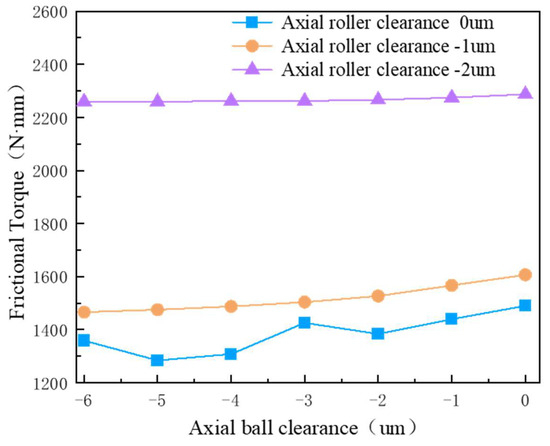
Figure 14.
Influence of axial clearance on bearing friction torque.
Figure 14 illustrates that the total friction torque of the bearing increases as the absolute value of the negative axial clearance of the cylindrical rollers rises. When the axial clearance of the cylindrical rollers is 0 μm, the total friction torque of the bearing generally shows a decreasing trend as the negative axial clearance of the steel balls increases. The minimum total friction torque occurs at an axial clearance of −5 μm for the steel balls. Beyond this point, when the negative axial clearance exceeds −5 μm, the increase in axial deformation within the bearing becomes negligible, and the variation in contact load of the rollers is minimal, resulting in insignificant changes in the friction torque produced by the cylindrical rollers. In contrast, as the negative clearance of the steel balls increases, their contact load steadily rises, which leads to a continuous increase in the friction torque of the steel balls. Consequently, the total friction torque of the bearing gradually increases. When the axial clearance of the cylindrical rollers is −1 μm, the total friction torque of the bearing decreases gradually as the negative axial clearance of the steel balls increases. This phenomenon occurs because the increase in contact deformation of the axial cylindrical rollers diminishes with the rising negative axial clearance of the steel balls, leading to a reduction in the friction torque generated by the cylindrical rollers that surpasses the increase in friction torque produced by the steel balls. Consequently, the total friction torque of the bearing experiences a continuous decrease. Conversely, when the axial clearance of the cylindrical rollers is −2 μm, the total friction torque of the bearing remains relatively constant despite the increase in the negative axial clearance of the steel balls. In this scenario, both the upper and lower rows of axial rollers are subjected to load, and the variation in steel ball clearance exerts minimal influence on the rollers. As a result, the decrease in friction torque generated by the rollers is nearly equivalent to the increase in friction torque produced by the steel balls due to the negative clearance, causing the total friction torque of the bearing to remain essentially unchanged.
In summary, to optimize the loading of rolling elements while minimizing the friction torque of the bearing, this study recommends setting the axial clearance of the cylindrical rollers to −1 μm and the axial clearance of the steel balls to −5 μm.
6.1.2. Influence of Axial Steel Ball Groove Curvature Radius Coefficient on Bearing Friction Torque
An analysis was conducted on the influence of varying axial steel ball groove curvature radius coefficients, ranging from 0.505 to 0.54, on the total friction torque of the bearing when subjected to an axial load of 5 kN. The axial roller clearance was measured at −1 μm, while the steel ball clearance was recorded at −5 μm. The results of this analysis are presented in Figure 15.
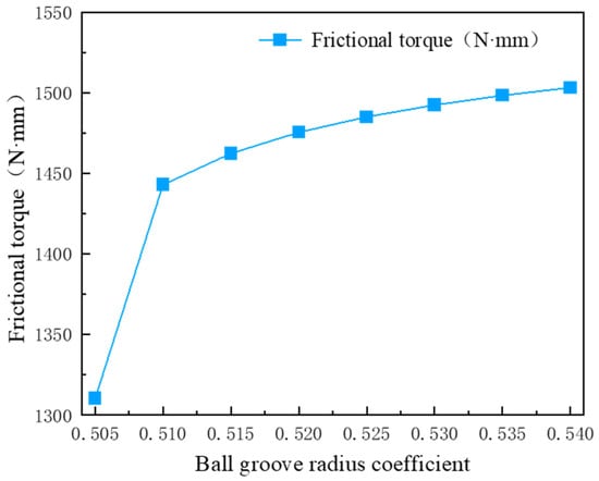
Figure 15.
Influence of steel ball groove curvature radius coefficient on friction torque.
Figure 15 illustrates that as the curvature radius coefficient of the steel ball groove increases from 0.505 to 0.51, there is a rapid increase in the total friction torque of the bearing. Beyond a coefficient of 0.51, the total friction torque increases at a slower rate and approaches stability. A larger curvature radius coefficient indicates a lesser degree of close fit between the steel ball and the groove. Under load, this results in a reduced contact area between the steel ball and the groove, consequently decreasing the proportion of the load supported by the steel ball. As a result, the load carried by the axial rollers and the deformation of the bearing increase correspondingly, leading to a rise in the total friction torque of the bearing. Given the manufacturing challenges associated with the groove and the overall structural constraints of the bearing, it is reasonable to establish the curvature radius coefficient of the axial steel ball groove within the range of 0.515 to 0.53.
6.1.3. Influence of Axial Load Application Position on Bearing Friction Torque
When both the axial load and radial load are set at 3 kN, the axial roller clearance is measured at −1 μm, while the steel ball clearance is recorded at −5 μm. The curvature radius coefficient of the steel ball groove is 0.52. The eccentric distances corresponding to the axial load are defined as 0 m, 0.1 m, 0.2 m, 0.3 m, 0.4 m, 0.5 m, and 0.6 m. This configuration simulates an axial load of 3 kN alongside overturning moment loads of 0 N·m, 300 N·m, 600 N·m, 900 N·m, 1200 N·m, 1500 N·m, and 1800 N·m, respectively. The analysis focuses on the impact of the eccentric distance of the axial load on the bearing friction torque, with the results illustrated in Figure 16.
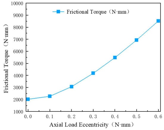
Figure 16.
Influence of axial load eccentricity on bearing friction torque.
Figure 16 illustrates that the total friction torque of the bearing increases progressively with the axial load eccentricity. The initial slow growth can be attributed to the pre-deformation induced by the axial negative clearance of the bearing, which diminishes the overturning moment. However, when the overturning moment reaches a substantial level, the impact of the negative clearance becomes less pronounced. Consequently, in practical engineering applications, it is advisable to minimize the eccentricity of the axial load.
6.1.4. Influence of the Numerical Ratio of Axial Steel Balls to Rollers on Bearing Friction Torque
When both the axial load and radial load are set at 3 kN, the overturning moment is measured at 600 N·m. The axial roller clearance is recorded at −1 μm, while the steel ball clearance is noted as −5 μm. Additionally, the curvature radius coefficient of the steel ball groove is 0.52. The ratios of axial steel balls to rollers are configured as 31/31, 42/21, and 48/16, respectively. This study analyzes the impact of varying ratios of axial steel balls to rollers on the bearing friction torque, with the results illustrated in Figure 17.
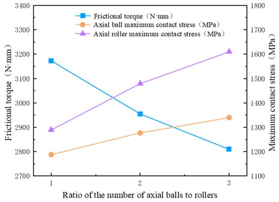
Figure 17.
Influence of the ratio of axial steel balls to rollers on bearing friction torque.
Figure 17 illustrates that the bearing friction torque decreases as the ratio of axial steel balls to rollers increases, while the maximum contact stress between the axial steel balls and rollers concurrently rises with this ratio. As the ratio of axial steel balls to rollers increases—indicating an increase in the number of steel balls and a decrease in the number of rollers—the deformation of the bearing under load becomes more pronounced. This results in an increase in the maximum contact load between the steel balls and rollers, thereby elevating the maximum contact stress experienced by both. Given that the friction torque produced by rollers is significantly greater than that produced by steel balls under equivalent deformation, the total friction torque of the bearing diminishes as the number of rollers is reduced. When the ratio of axial steel balls to rollers equals 1, the maximum contact stresses for both components are relatively low and comparable. Consequently, it is more prudent in engineering applications to establish the axial steel balls to rollers ratio at 1.
6.1.5. Influence of Roller Crowning Methods on Bearing Friction Torque
Under the conditions of an axial load and radial load of 3 kN each, alongside an overturning moment of 600 N·m, an axial roller clearance of −1 μm, a steel ball clearance of −5 μm, and a steel ball groove curvature radius coefficient of 0.52, the influence of various roller crowning methods on bearing friction torque was analyzed. The results are illustrated in Figure 18, where “a” denotes logarithmic crowning, “b” indicates arc-slope crowning with the centers positioned at both sides, “c” represents arc-slope crowning with the center on the midline, “d” signifies full convex roller crowning, and “e” depicts straight rollers.
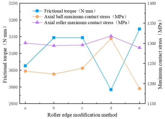
Figure 18.
Influence of chamfering method on bearing friction torque.
Figure 18 illustrates that the bearing friction torque is minimized when employing full convex roller crowning, although this configuration results in the highest maximum contact stresses between the steel balls and rollers. Conversely, while straight rollers exhibit the lowest maximum contact stresses, they correspond to the highest bearing friction torque. In conclusion, the logarithmic crowning method emerges as the optimal choice.
6.2. Analysis of Multi-Factor Coupling Effects
Building upon the single-factor analysis, a multi-factor coupling analysis is conducted to further investigate the interaction effects of multiple key parameters on friction torque. An orthogonal design method based on the numerical model is employed to perform the combined parameter study. Four major factors are selected: axial roller clearance, ball clearance, ball groove curvature radius coefficient, and axial load eccentricity. Each factor is set at three representative levels, and an L9(34) orthogonal array is constructed, resulting in a total of nine test scenarios. The friction torque model is utilized to calculate the response value under each parameter combination. Main effect analysis and range analysis are subsequently performed to quantify the influence of each factor on friction torque and to determine the sensitivity ranking. This reveals the evolution characteristics of friction performance under different parameter combinations. This analytical approach not only identifies the dominant control factors but also provides a multidimensional design reference for structural optimization and parameter configuration of the bearing.
The main factors and their corresponding levels are presented in Table 2.
Table 2.
Factors and corresponding levels.
The orthogonal design based on the numerical model yields the parameter combinations and corresponding friction torque results, as shown in Table 3.
Table 3.
Orthogonal design combinations and numerical analysis results.
- (1)
- Based on the data in Table 3, the main effect plots for each factor are obtained, as shown in Figure 19.
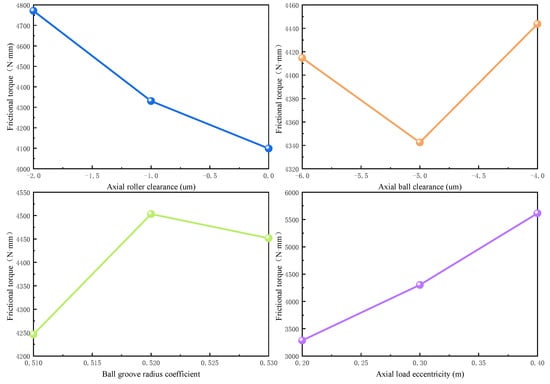 Figure 19. Main effect plots of each factor.
As shown in Figure 19, the trends of friction torque variation at different levels of each factor generally align with the results from the previous single-factor analysis. Notably, the main effect curve for the load application position exhibits a clear upward trend, confirming its amplifying effect on friction response with increasing eccentricity. This observation is consistent with the single-factor analysis conclusion that friction torque significantly increases as load eccentricity increases. Similarly, the effects of axial roller clearance and groove curvature radius coefficient on friction torque remain consistent with earlier findings. Within certain ranges, an increase in clearance or a decrease in curvature radius leads to changes in contact stiffness, thereby influencing friction characteristics. In contrast, the main effect variation of ball clearance is relatively small, indicating its weaker influence on overall friction performance within the considered range. This aligns with the single-factor result showing the low sensitivity of ball clearance.
Therefore, the main effect plots not only validate the conclusions of the single-factor analysis from a multi-factor perspective but also reinforce the understanding of the sensitivity ranking of parameters, providing valuable data support for subsequent optimization.
- (2)
- Evaluation of the influence degree of each factor on the friction torque.
Based on the numerical results presented in Table 3, the average friction torque values at three levels for each factor were calculated. The range indicator, defined as the difference between the maximum and minimum average values, was employed to quantify the sensitivity of each factor. The results of these calculations are illustrated in Figure 20.
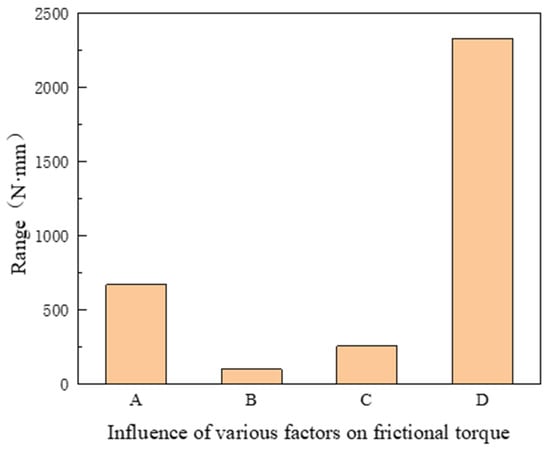
Figure 20.
Influence levels of various factors on friction torque. A—Axial roller clearance; B—Axial ball clearance; C—Groove curvature radius coefficient; D—Axial load eccentricity.
As shown in Figure 20, the sensitivity ranking of factors affecting friction torque is as follows: axial load eccentricity, axial roller clearance, groove curvature radius coefficient, and axial ball clearance. This trend aligns with the main effect plots, thereby validating the reliability of the analytical conclusions.
7. Conclusions
This paper analyzes the formation mechanism of the friction torque in a novel ball–roller composite turntable bearing. A corresponding calculation model is constructed, and the model’s validity is verified through experimental data. Based on the investigation of the friction torque characteristics of the novel ball–roller composite turntable bearing, the following conclusions are drawn:
- (1)
- The friction torque of the novel ball–roller composite turntable bearing is primarily generated by the rollers. The negative axial roller clearance has a significant impact on the friction torque. By appropriately adjusting the clearance parameters—specifically, setting the axial roller clearance to -1 μm and the axial steel ball clearance to −5 μm—it is possible to achieve a more balanced load distribution between the axial rollers and the steel balls, thereby reducing the overall friction torque;
- (2)
- By comparing the friction torque and contact stress at various ratios of steel balls to rollers, it is observed that a 1:1 ratio of axial steel balls to rollers yields optimal friction and load-carrying performance, demonstrating excellent overall operational characteristics;
- (3)
- The curvature radius coefficient of the axial steel ball raceway significantly influences the friction torque; as this coefficient increases, the friction torque also increases markedly. Considering the challenges associated with processing and structural adaptability, the recommended range for the curvature radius coefficient is between 0.515 and 0.53;
- (4)
- The eccentric distance of the axial load significantly influences the friction torque. As the eccentric distance increases, the friction torque also rises. Therefore, in engineering design and application, it is essential to minimize load eccentricity to enhance the operational stability and service life of the bearing;
- (5)
- Different cylindrical roller crowning methods significantly influence the friction characteristics and contact stress distribution of bearings. Notably, the cylindrical roller structure featuring logarithmic crowning demonstrates superior performance in reducing friction torque and alleviating contact stress.
Author Contributions
Conceptualization, Z.Z. and H.T.; methodology, Z.Z. and W.L.; software, W.L.; validation, H.T., W.L. and Z.Z.; formal analysis, W.L.; investigation, X.S. and W.Z.; resources, Z.Z.; data curation, Z.Z. and W.L.; writing—original draft preparation, H.T. and W.L.; writing—review and editing, H.T., W.L. and Z.Z.; visualization, W.L.; supervision, Z.Z. and X.S.; project administration, Z.Z. and W.Z.; All authors have read and agreed to the published version of the manuscript.
Funding
This research was funded by the National Natural Science Foundation of China (52105182), the “Key Research and Development Program” of Heilongjiang Province under the “Jiebang Guai-shuai” Science and Technology Tackling Project (2023ZXJ04A02), Henan Province science technology research project (252102220018).
Data Availability Statement
Data are contained within the article.
Conflicts of Interest
Author Xiuhua Shao was employed by the company Luoyang Xinkai Bearings Technology Co., Ltd. The remaining authors declare that the research was conducted in the absence of any commercial or financial relation-ships that could be construed as a potential conflict of interest.
References
- Palmgren, A. Ball and Roller Bearing Engineer, 3rd ed.; Svenska Kullager Fabriken (SKF) Industries Incorporration: Philadelphia, PA, USA, 1959. [Google Scholar]
- Chiu, Y.P.; Myers, M. A rational approach for determining permissible speed for needle roller bearings. SAE Trans. 1998, 107, 330–337. [Google Scholar]
- Ghanbari, A.; Khanmohamadi, S. A new test rig for friction torque measurement in ball bearing. Wseas Trans. Syst. 2006, 9, 2172–2177. [Google Scholar]
- Li, X.; Liu, J.; Huang, S.; Pan, G. Friction moment calculation method for tapered roller bearings under combined loads. Sci. China Technol. Sci. 2024, 67, 2565–2578. [Google Scholar] [CrossRef]
- Ye, B.; Zhang, K.; Zuo, Q.; Zhang, L.; Shan, X. Test and analysis of friction torque of double-row angular contact ball bearing under vacuum environment. Ind. Lubr. Tribol. 2024, 76, 160–166. [Google Scholar] [CrossRef]
- Fernandes, C.; Martins, R.; Seabra, J. Friction torque of thrust ball bearings lubricated with wind turbine gear oils. Tribol. Int. 2013, 58, 47–54. [Google Scholar] [CrossRef]
- Hammami, M.; Martins, R.; Fernandes, C.; Seabra, J.; Abbes, M.S.; Haddar, M. Friction torque in rolling bearings lubricated with axle gear oils. Tribol. Int. 2018, 119, 419–435. [Google Scholar] [CrossRef]
- Zhang, K.; Li, J. Analyzing Calculation for Friction Moment of Ball Bearings. Bearing 2001, 1, 8–11. [Google Scholar]
- Deng, S.; Jia, Y. Friction Torque Characteristics of Thrust Ball Bearings. Acta Armamentarii 2015, 36, 1615–1623. [Google Scholar]
- Deng, S.; Li, M.; Lu, Y.; Dai, Y. Study of Friction Torque of Needle Roller Thrust Bearings. Acta Armamentarii 2015, 36, 1347–1355. [Google Scholar]
- Goncz, P.; Potočnik, R.; Glodež, S. Computational model for determination of static load capacity of three-row roller slewing bearings with arbitrary clearances and predefined raceway deformations. Int. J. Mech. Sci. 2013, 73, 82–92. [Google Scholar] [CrossRef]
- Zupan, S.; Prebil, I. Carrying angle and carrying capacity of a large single row ball bearing as a function of geometry parameters of the rolling contact and the supporting structure stiffness. Mech. Mach. Theory 2001, 36, 1087–1103. [Google Scholar] [CrossRef]
- Amasorrain, J.; Sagartzazu, X.; Damián, J. Load distribution in a four contact-point slewing bearing. Mech. Mach. Theory 2003, 38, 479–496. [Google Scholar] [CrossRef]
- Chen, G.; Xu, S.; Yang, Y.; Wang, Y.; Deng, S. Contact stress analysis on large-sized four-contact-point ball bearing with negative axial play. J. Mech. Transm. 2009, 33, 83–85, 91. [Google Scholar]
- Deng, B. Analysis of the influence of raceway structure on contact characteristics of turntable bearing. J. Phys. 2021, 1732, 012192. [Google Scholar] [CrossRef]
- Krynke, M.; Borkowski, S.; Selejdak, J. Analysis of influence of bearing clearance on the static carrying capacity of multi-row slewing bearings. Period. Polytech. Transp. Eng. 2014, 42, 43–48. [Google Scholar] [CrossRef]
- Zhang, H.; Chen, S.; Dou, Y.; Fan, H.; Wang, Y. Mechanical model and contact properties of double row slewing ball bearing for wind turbine. Rev. Adv. Mater. Sci. 2021, 60, 112–126. [Google Scholar] [CrossRef]
- Peter, G.; Miran, U.; Srecko, G. Computational assessment of the allowable static contact loading of a roller-slewing bearing’s case-hardened raceway. Int. J. Mech. Sci. 2015, 94, 174. [Google Scholar]
- Ju, S.; Horng, T.; Cha, K. Comparisons of contact pressures of crowned rollers. Proc. Inst. Mech. Eng. Part J J. Eng. Tribol. 2000, 214, 147. [Google Scholar] [CrossRef]
- Wang, H.; Hu, B.; Chen, Y. Calculation on friction torque of blade bearings without load based on finite element analysis. Bearing 2011, 1–3. [Google Scholar] [CrossRef]
- Wang, S.; Xu, M.; Shi, X. Comparative analysis on mechanical properties for two categories of slewing bearings. Chin. J. Constr. Mach. 2010, 8, 24–28. [Google Scholar]
- Gärtner, M.; Brecher, C.; Neus, S.; Eckel, H.-M.; Bartelt, A.; Hoppert, M.; Ilkhani, M.R. The friction of radially loaded hybrid spindle bearings under high speeds. Machines 2023, 11, 649. [Google Scholar] [CrossRef]
- Yang, X.; Zhang, T.; He, L.; Bu, L.; Liu, M.; Li, M. Friction torque characteristic of large-size double row four-point contact ball bearings. Acta Energiae Solaris Sin. 2021, 42, 356–363. [Google Scholar]
- Li, J.; Li, Y.; Zhong, Z. Analysis of friction torque of wind turnine main bearing with three-row rollers under combined loads. Acta Energiae Solaris Sin. 2024, 45, 597–606. [Google Scholar]
- Zhang, Z.; Zhou, P.; Li, W.; Wang, H. Study of friction torque characteristics of YRT rotary table bearing. Acta Armamentarii 2019, 40, 1495–1502. [Google Scholar]
- Zhang, Z.; Zhang, K.; Wang, H. Friction torque characteristic of ball-roller combined turntable bearing. Aerosp. Power 2020, 35, 2664–2672. [Google Scholar]
- Deng, S.; Xue, J.; Niu, R. Principles of Rolling Bearing Design; Standards Press of China: Beijing, China, 2023. [Google Scholar]
- Deng, S.; Sheng, M.; Deng, K.; Dai, Y. Friction torque of double-row spherical roller bearings. Aerosp. Power 2017, 32, 1666–1675. [Google Scholar]
- Wang, Y.; Deng, S.; Yang, H. Analysis for traction characteristics of HKD aviation lubricating oil in rolling/sliding contacts. Acta Armamentarii 2009, 30, 958–961. [Google Scholar]
- Deng, S. Constitutive equation of a new aviation lubricating oil. Chin. J. Mech. Eng. 2007, 20, 28. [Google Scholar] [CrossRef]
- Matsuyama, H. High efficiency and tribology in rolling bearings. Jtekt Eng. J. 2012, 1009, 108–113. [Google Scholar]
Disclaimer/Publisher’s Note: The statements, opinions and data contained in all publications are solely those of the individual author(s) and contributor(s) and not of MDPI and/or the editor(s). MDPI and/or the editor(s) disclaim responsibility for any injury to people or property resulting from any ideas, methods, instructions or products referred to in the content. |
© 2025 by the authors. Licensee MDPI, Basel, Switzerland. This article is an open access article distributed under the terms and conditions of the Creative Commons Attribution (CC BY) license (https://creativecommons.org/licenses/by/4.0/).