Article

Research on Adaptive Drilling Control Technology Based on Coal Rock Traits During the Drilling Process

1
Xuhai College, China University of Mining and Technology, Xuzhou 221008, China
2
School of Mechanical and Electrical Engineering, China University of Mining and Technology, Xuzhou 221008, China
3
Changsha Mine Research Institute Co., Ltd., Changsha 410012, China
*
Author to whom correspondence should be addressed.
Machines 2025, 13(2), 133; https://doi.org/10.3390/machines13020133
Submission received: 16 January 2025 / Revised: 5 February 2025 / Accepted: 7 February 2025 / Published: 10 February 2025
(This article belongs to the Section Automation and Control Systems)

Abstract

:
The anti-punch drilling robot is a core piece of equipment used to realize unmanned drilling and pressure relief operations in underground coal mines. Adaptive drilling, conducted according to the coal rock properties encountered during drilling, is essential to improve the safety and efficiency of the pressure relief working face. This paper analyzed the composition of the anti-punch drilling robot drilling system and workflow of the drilling system and then calculated the optimal rotary speed and the optimal feed speed for different Platts hardness coefficients of the coal rock through the analysis of the drilling rod force. Based on the characteristics of the drilling electrohydraulic control system, a rotary adaptive controller based on a self-resistant control algorithm and a feed adaptive controller based on sliding mode variable structure control were designed. A joint simulation was carried out using AMESim 2020.1 and Simulink 2020b software to analyze the control performance of each controller. Finally, an experimental platform for the drilling robot electrohydraulic control system was constructed; different hardness coefficients of concrete specimens were used to simulate the hardness of the coal rock with different traits. Single coal rock hardness experiments and drilling experiments with sudden changes in coal rock hardness were carried out. The experimental results showed that the adaptive control strategy proposed in this paper satisfies the requirements of drilling system control.

1. Introduction

Coal is one of the major energy sources in China. Impact ground pressure disasters occur frequently in the process of coal mining and pose a great threat to the safe and efficient mining of deep resources. The anti-impact drilling robot is a key piece of equipment for pressure-relief drilling operations in underground coal mines; its continuous, safe, and reliable operation is crucial for realizing the high productivity and high efficiency of pressure-relief operations [1]. Drilling performance largely depends on the drilling system [2]. In the process of drilling in areas of high ground stress and where the mechanical properties of the surrounding rock are variable, drilling robots cannot effectively respond to the discontinuous and sudden changes in the drilling state caused by the different coal rocks, which leads to low drilling efficiency and problems such as drill jamming and drill holding. Therefore, in order to improve drilling efficiency and realize an intelligent and unmanned drilling process, it is necessary to identify the drilling coal rock traits and ensure the adaptive regulation of the drilling robot during the drilling process [3,4].
With the development of intelligent drilling rigs, scholars at home and abroad have carried out a considerable amount of research on drilling system control. Hu Zhijian et al. established a drilling control simulation system using improved PID and Fuzzy–PID algorithms for closed-loop control of the feed force, speed, and drilling speed [5]. The results showed that the dynamic response of the drilling control simulation system was fast; control accuracy was high, anti-interference ability was strong, and the maximum control error was about 10%. The system was shown to control the drilling process well. Zhao, X.Y. et al. proposed an electrohydraulic proportional drilling control system for the rotary mechanism of a drilling rig that was designed and studied on the basis of analyzing the characteristics of a PID control algorithm and fuzzy control algorithm [6]. The simulation experiments showed that the Fuzzy–PID algorithm effectively improved the control performance of the control system with good environmental adaptability. Qingfeng Wang et al. developed an adaptive control technology based on a differential evolutionary algorithm according to the mechanism of intelligent sensing and adaptive control of drilling conditions, which realized the automatic optimization of the control vector of the drilling robot [7]. Ground drilling tests showed that the intelligent sensing of drilling conditions and adaptive control technology enabled the drilling robot to automatically adjust control parameters faster when sudden changes in the rock formation are encountered, ensuring that the drilling robot maintains an efficient and stable drilling state. Zhao J et al. proposed a control system for the weight of the drill bit and the penetration rate of the drilling robot; based on this, a dual-loop fuzzy proportional-integral derivative (PID) control algorithm for differential pressures and flow rates was used to control the bit weight and penetration rate [8]; a simulation model of the dual-loop fuzzy–PID control algorithm was also established.
Cavanough, G.L. et al. proposed a drilling control system to superimpose the oscillating force signal to the drill feed force and mediate the signal from the rotating torque of the drill bit; the obtained, demodulated signal was used to control the drill bit [9]. Testing proved that the control was reliable and able to improve drilling efficiency. Haber, R. E. et al. proposed a fuzzy control system based on the cross-entropy exact mathematical framework to obtain optimal fuzzy controller parameters by minimizing the integral time absolute error (ITAE) performance metric l [10]. Experimental results showed that the application of the optimal fuzzy-controlled drilling system reduced rapid bit wear and catastrophic bit breakage. Nurzat Rasol proposed a derivative and integral sliding mode controller [11]. The control method involved replacing the induced integral of the tracking error and the derivative of the tracking error as state variables; the developed controller utilized nonlinear derivative control to suppress system oscillations and to increase system damping as the error approached zero. Simulation results showed that the controller had a fast dynamic response and improved the accuracy of the drilling control system. Detournay et al. proposed a directional drilling model based on delay differential equations to formulate the borehole generation problem as a tracking problem and established a model-based robust control strategy to control the drilling system; a case study illustrated the effectiveness of the proposed methodology [12]. Inyang, I. J. et al. proposed a method to control the drilling tool attitude in a drilling system using a bilinear model as the basis for a bilinear proportional-integral (BPI) controller design; the simulation results showed that the proposed BPI controller is more effective, robust and stable than the existing PI controller for directional drilling tool attitude control [13]. Georgiou, A. et al. proposed a robust model predictive control scheme to control the drilling system, which utilized a robust positive invariant (RPI) set control method and a state feedback strategy computed offline using model approximation techniques to improve its stability and computational efficiency; the performance of the scheme was verified through simulations [14]. Abdelbaset, Laib et al. proposed an optimal mixed-interval type 2 fuzzy–PID+I logic controller (OH-IT2FPID+I) based on the utility swarm optimization algorithm for multi-degree-of-freedom drilling systems; the results confirmed the control performance of the proposed controller in all different test scenarios [15].
Due to the existence of commutation hysteresis, nonlinearity, external interference from the electrohydraulic system and the unmodeled dynamics of the proportional valve, the uncertainty and complexity of models and the difficulties in maintaining control are increased [16]. At the same time, during the drilling process, coal and rock characteristics change, and slag discharge is not smooth; if the control strategy is not adjusted in time, accidents, such as jamming and reporting drilling, can easily occur [17]. In order to solve the above problems, this paper takes the anti-punch drilling robot drilling system as its research object, analyzes the structure of the anti-punch drilling robot drilling system, calculates the optimal drilling parameters based on the Platt hardness coefficient of the coal rock, and designs an auto-resistant controller (ADRC) based on the rotary motor rotational speed [18]. A sliding-mode variable-structure controller (SMC) based on the feed speed of the feed cylinder is also presented. A joint simulation model is used to analyze the effectiveness of the control strategies and experimentally verify them.

2. Composition of Drilling System and Calculation of Optimal Drilling Parameters

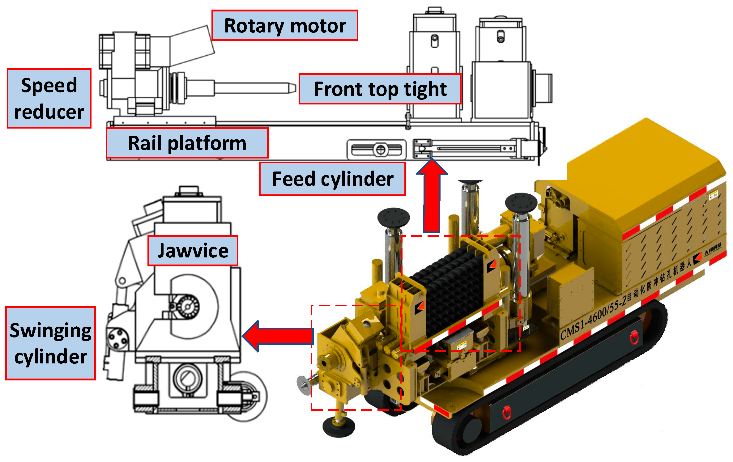
2.1. Drilling System Components

The anti-punch drilling robot drilling system is shown in Figure 1, and mainly consists of a slewing device, feeding device, and gripper. The slewing device is composed of a slewing motor and reducer to realize the rotation of the drill pipe, including forward and reverse rotations. The feeding device is composed of a feeding cylinder, guide platform and front top tightening device to realize the feeding action of the drill pipe, including advancing and retreating. The front top tightening device is used to support the drilling direction of the guide platform and reduce the impact of vibrations caused by the machine itself or by the loads of coal and rock on the drilling work. The clamp consists of a front vise, a front vise swing cylinder, and a rear vise to realize the functions of clamping, tightening, and dismantling the drill pipe.

2.2. Drilling System Workflow

The drilling system drilling work process is shown in Figure 2. During the drilling process, after the drilling system attitude is stabilized, the front top extends out and completes the rod feeding work through the cooperation of the shuttle arm and the hand clamp. The rear vise and the slewing and drilling devices cooperate to complete the threaded connection between the rotary axis and the drill pipe. The drilling can then be carried out. In the process of retiring the rods, through the cooperation of the front and rear vises, swing cylinder, and hand vise, the threaded connections between the current drill rod and the previous drill rod, and between the current drill rod and the front top, are unlocked successively. The shuttle arm and hand vise transport the drill rods to the drilling tool store to complete the retiring process.
During the drilling process, the working sequence of the spatial movements of the drill pipe is as follows: hand clamp grasping → following the shuttle arm to move towards the drilling part → the front top to tighten the drill pipe → the slewing motor to tighten the threaded connection → the drill pipe rotates and feeds. In the coordinate system shown in Figure 3, after the hand clamp grasps the drilling tools on the jacking plate, the hydraulic motor drives the shuttle arm to drive the hand clamp along the direction of OY1 to transport the drilling tools to the drilling part; the drilling rod rotates and feeds along the OZ2 axis; the spatial movement of the drilling rod in the process of drilling back is the opposite of that in the process of drilling in.

2.3. Calculation of Optimal Drilling Parameters

During the drilling process, the coal rock properties are different. In order to characterize the difficulties in coal rock drilling, the Soviet scholar Protodyakonov proposed the Platt hardness scale to characterize the hardness of coal rock [19,20].
During the working process of the anti-punch drilling robotic drilling system, assuming that the coal rock properties and the drill pipe remain unchanged, the drilling speed will be related to the rotational speed and torque of the rotary mechanism, and to the feed force and feed speed of the feed mechanism. In order to obtain the optimal drilling parameters of the rotary mechanism and feed mechanism, a mechanical analysis of the drilling and cutting process is required [21].
From the force analysis diagram in Figure 4, the rotary diameter of the drill pipe can be obtained as follows:
D = 0.5 ( D 1 + D 2 )
In the formula, D1 is the outer diameter of drill pipe head in mm and D2 is the outer diameter of drill pipe head in mm.
When the drill bit rotates one way, the spiral rise angle α of the drill pipe is as follows:
t g α = l / ( π d )
In the formula above, l is the drill pipe feed during drilling in mm/r.
During the drilling process, the drill bit at point A will be subjected to the axial feed force in the horizontal direction with the drill pipe and the perpendicular to the drill pipe in the longitudinal direction. The circumferential tangential force of the joint direction of these two forces to be in the same direction as the drilling direction, as follows:
tan α = F 1 / F 2
In the above formula, F1 is the axial feed force at the drill bit cutting edge, N and F2 is the circumferential tangential force at the drill bit cutting edge, N.
The tangential force around the circumference of the drill pipe is as follows:
F 2 = M D × 10 3
In the above formula, M is the output torque of the slewing mechanism, N∙m.
When the drilling system is working, the drill bit contacts the coal rock to produce friction and the coal rock is subjected to cutting and squeezing. When the squeezing force of the drill bit on the coal rock is greater than the compressive strength of the coal rock, the coal rock will be broken and the area of point A is as follows:
A = l ( D 1 D 2 ) 4
l = c M D 1 2 D 2 2 σ
In the above formula, c is the speed constant of the drill bit when cutting coal rock in mm⋅r/min.
The drill pipe feed is directly proportional to the rotary torque and the feed of the drill bit is also inversely proportional to the square difference between the outer and inner diameters of the drill bit and the compressive strength of the rock. During the drilling process, the feed volume needs to be selected according to different coal rock hardness coefficients.
An increase in rotary motor speed will improve drilling efficiency; however, when rotary speeds are too high and when there is too little contact time between the drill bit and coal rock, drilling difficulties will increase and drilling will be affected. Different coal rock traits require different rotational speeds and drilling speeds. The relationship between the rotary speed and coal rock hardness is as follows:
n = c f D
In the above formula, n is the optimal rotational speed of the slewing mechanism, r/min and f is the Platt hardness coefficient of the coal rock.
The compressive strength of the coal rock is related to the Platt hardness coefficient of the coal rock, as follows:
σ = 10 f
The slewing mechanism load torque is as follows:
M = l D 1 2 D 2 2 σ / c
In the drilling process, the drill pipe is mainly used to transmit torque and feed force; if the feed force is too large, the drill pipe will produce longitudinal vibrations, and thus deformations or fractures, which seriously affect drilling accuracy. At the same time, if the feed speed is too great and does not match the rotary speed, the drill may be jammed or clutched. The relationship between the required feed force of the drill bit and the axial thrust of each drilling wing is as follows:
F T = 2 F 1
In the above formula, FT is the load force applied to the feed mechanism, N, as follows:
F T = c l M π D 1 + D 2
It is obtained from the feed per revolution and the slewing speed, as follows:
v = l n
The optimal control parameters for different coal rock hardness coefficients during the drilling process can be obtained through calculation, as shown in Table 1.

3. Research on Control Strategy of Drilling System

3.1. Control Program Design

In order to obtain the non-linearity and time-varying parameters of the anti-punch drilling robot drilling system, the optimal drilling parameters are determined by the Platt hardness coefficient of the coal rock, the rotary speed is controlled by the ADRC controller, and the feed speed is controlled by the SMC controller. Optimal control of the anti-punch drilling robotic drilling system can then be achieved to satisfy the stability requirements of the drilling system, and enable the system to adapt to changes in coal rock properties. Reliable and efficient operation of the anti-punching drilling robot can therefore be guaranteed, and the drilling efficiency of the anti-punch drilling robot is improved.
The block diagram of the control strategy of the drilling system is shown in Figure 5. When different coal rock hardness values are encountered, the control system matches the optimal rotational speed and the optimal feed rate for drilling. The control system first controls the rotary hydraulic motor to output the optimal rotational speed through the ADRC controller. Then, the SMC control controls the hydraulic output to output the optimal feed speed at the current rotational speed.

3.2. Controller Design

3.2.1. ADRC Controller

Self-immunity control is a new type of control method that represents an improvement on the PID control algorithm, which has structural characteristics that do not depend on the control object model , and do not distinguish between internal and external disturbances in the system. The commonly used self-immunity controller mainly consists of three parts: a tracking differentiator (TD), extended state observer (ESO), and nonlinear state error feedback (NLSEF) control rate components [22,23], the schematic diagram of the controller is shown in Figure 6.
Differential Tracker: The input signal of the tracking differentiator is the given RPM n 0 , the output signal is the transition desired RPM n 1 , and the desired RPM differentiation is n 2 ; the formula is as follows:
fh = fhan n 1 n 0 , n 2 , r 0 , h n 1 = n 1 + h · v 2 n 2 = n 2 + h · fh
In the formula above, n0 is the given speed, n1 is the desired speed, n2 is the desired speed differentiation and the parameters r, ℎ are the adjustable parameters of the tracking differentiator.
Using the linearly expanding state observer LESO, e is the difference between the estimated angular velocity Z1 and the output y. This electrohydraulic system is a third-order system; thus, the error is loaded into the disturbance term Z4.
The system state with perturbations is estimated using the dilated state observer, as follows:
e = z 1 y z 1 = z 1 + h · z 2 β 01 · e z 2 = z 2 + h · z 3 β 02 · e z 3 = z 3 + h · z 4 β 03 · e + b 0 · u z 4 = z 4 + h · β 04 · e
In the above formula, Y outputs feedback and β is the calibrated control parameters.
To obtain the state error feedback rate, the inputs to the error feedback control are the difference between the transition target speed n1 and the observed speed z1, the difference between the differential n2 of the target speed and the observed speed z2, the difference between the differential n3 of the target speed and the observed speed z3, and the output is u0, as follows:
e 1 = n 1 z 1 , e 2 = n 2 z 2 e 3 = n 3 z 3 u 0 = k e 1 , e 2 , e 3 , p
In the above formula: k is the gain coefficient and u is the self-immunity control rate.
The perturbation compensation process is as follows:
u = u 0 z 4 t / b 0

3.2.2. SMC Controller

The sliding mode variable structure control method is a method of using the sliding mode surface to control the target quantity, which can then obtain the ideal control effect [24]. Sliding mode variable structure control is used for control systems with uncertain control parameters and varying loads. The sliding mode variable structure controller has strong robustness and control discontinuity characteristics [25]. The motion trajectory of the sliding mode variable structure control can be divided into two main phases. The first phase is the movement of the system towards the slip mode surface in any initial state, in which the system gradually approaches the intended slip mode surface. The second phase occurs when the system successfully reaches the slide mold surface and enters the phase of motion along the slide mold surface, in which the system will carry out a specific motion trajectory on the slide mold surface. Therefore, the design of the sliding mold variable structure controller can be divided into two parts: the first part is the design of the sliding mold surface; the second part is the design of the control law [26].
The controlled object is a third-order system; X = x   x ˙   x ¨ T is each state variable of the system; r is set as the input signal and y is the output signal of the control system; the error of the system can be expressed as e = ry; the error vector of the system is defined as follows:
E = e 1   e 2   e 3 T = r y   r ˙ y ˙   r ¨ y ¨ T
The state space equations are as follows:
x ˙ 1 = x 2 x ˙ 2 = x 3 x ˙ 3 = ω 2 x 2 2 ξ ω x 3 + K ω 2 u y = x 1
The sliding mode switching function is as follows:
s = c 1 e 1 + c 2 e 2 + e 3
The state space equation of the control system is as follows:
E ˙ = 0 1 0 0 0 1 0 ω 2 2 ξ ω E + 0 0 K ω 2 u + 0 0 r + 2 ξ ω r ¨ + ω 2 r ˙
In order to satisfy s = c 1 e 1 + c 2 e 2 + e 3 = 0 , simplifying the differential equation for the motion of the sliding mode yields the following:
e ˙ 1 e ˙ 2 = 0 1 c 2 c 1 e 1 e 2
The design of the sliding mold variable structure controller for the anti-punch drilling robot drilling control system is shown in the equation below. ueq is the equivalent control used to realize the tracking of the system state so that the system structure along the sliding mold surface can complete the switching motion. usw is the switching control, the system state is under the control of the switching function to converge to the surface of the sliding mold and to weaken the system vibrations. For the switching control, the convergence law is used to describe the characteristics of the trajectory and velocity change of the sliding mode moving point in the process of gradually approaching the switching surface, as follows:
u = u e q + u s w
The equivalent control is as follows:
u e q = 1 K ω 2 ( c 1 ω 2 ) e 2 + ( c 2 2 ξ ω ) e 3 + r + 2 ξ ω r ¨ + ω 2 r ˙
The control rate for the switching control is as follows:
u s w = ε s a t s k s
Among them. s a t ( s ) = 1 s > Δ s s Δ k = 1 Δ 1 s < Δ
The controller for the sliding mode variable structure is designed as follows:
u = u e q + u s w = 1 K ω 2 ( c 1 ω 2 ) e 2 + ( c 2 2 ξ ω ) e 3 + r + 2 ξ ω r ¨ + ω 2 r ˙ + ε s a t ( s ) + k s
In the above formula, c1 and c2 are constants, ω is the intrinsic frequency of the proportional valve, and ξ is the damping of the proportional valve.

3.3. Controller Co-Simulation Model Building

In order to verify the effectiveness of the cooperative control strategy for slewing and feeding based on the drilling motor priority proposed in this section, a joint simulation platform of the slewing mechanism and feeding mechanism of the drilling system of the anti-punching drilling robot based on AMEsim 2020.1 and Simulink 2020b was constructed and is shown in Figure 7. Simulink was mainly used to design the slewing and feeding controllers designed; the AMEsim model contains the load-sensitive pump system, slewing hydraulic subsystem, and feeding hydraulic subsystem.

4. AMESim and Simulink Joint Simulation Analysis

The key to optimizing the drilling process of the anti-punch drilling robot is the control of the rotary and feed mechanism of the anti-punch drilling robot. The working state of the anti-punch drilling robot is affected by the coal rock properties. The design of the optimal drilling parameters of the drilling system of the anti-punch drilling robot is based on the hardness coefficients of the coal rock, which requires a detailed analysis of the coal rock properties and the mechanism of the anti-punch drilling robot used to break through the coal rock. In this section, the tracking performance of the rotary control strategy and the feed control strategy under different coal rock hardness coefficients were simulated and analyzed using a joint-simulation environment with AMESim and Simulink; the performance advantages and disadvantages of the control strategies are evaluated and compared.

4.1. Slewing Speed Control Strategy Based on Self-Immunity Control

In the working process of the anti-punch drilling robot drilling system, changes in coal rock hardness and coal rock traits occur. The different coal rock traits cause changes in the drilling system; therefore, it is necessary to make timely adjustments to the rotary speed in the process of turning. From the above analysis and calculation, it can be seen that the variations in coal rock properties can be characterized by the Platt hardness coefficient. The relationship between the coal rock hardness coefficient and loading torque is shown in Figure 8.
The coal rock coefficient in the drilling process is usually lower than 10; therefore, this paper selected coal rock with Platt hardness levels of 4, 8, and 6 to carry out the rotary simulation experiments. The corresponding desired rotary speeds were 232 r/min, 116 r/min, and 154 r/min. The simulation was carried out for 5 s according to the three different conditions. Figure 9 shows the rotary speed control curves and Figure 10 shows the rotary speed control tracking error.
The above results show that under different coal rock hardness coefficients and desired rotational speeds, the ADRC slewing controller has a faster response speed compared with the traditional PID controller. In addition, the ADRC slewing controller has a lower amount of overshooting, lower tracking errors, and a higher control accuracy.

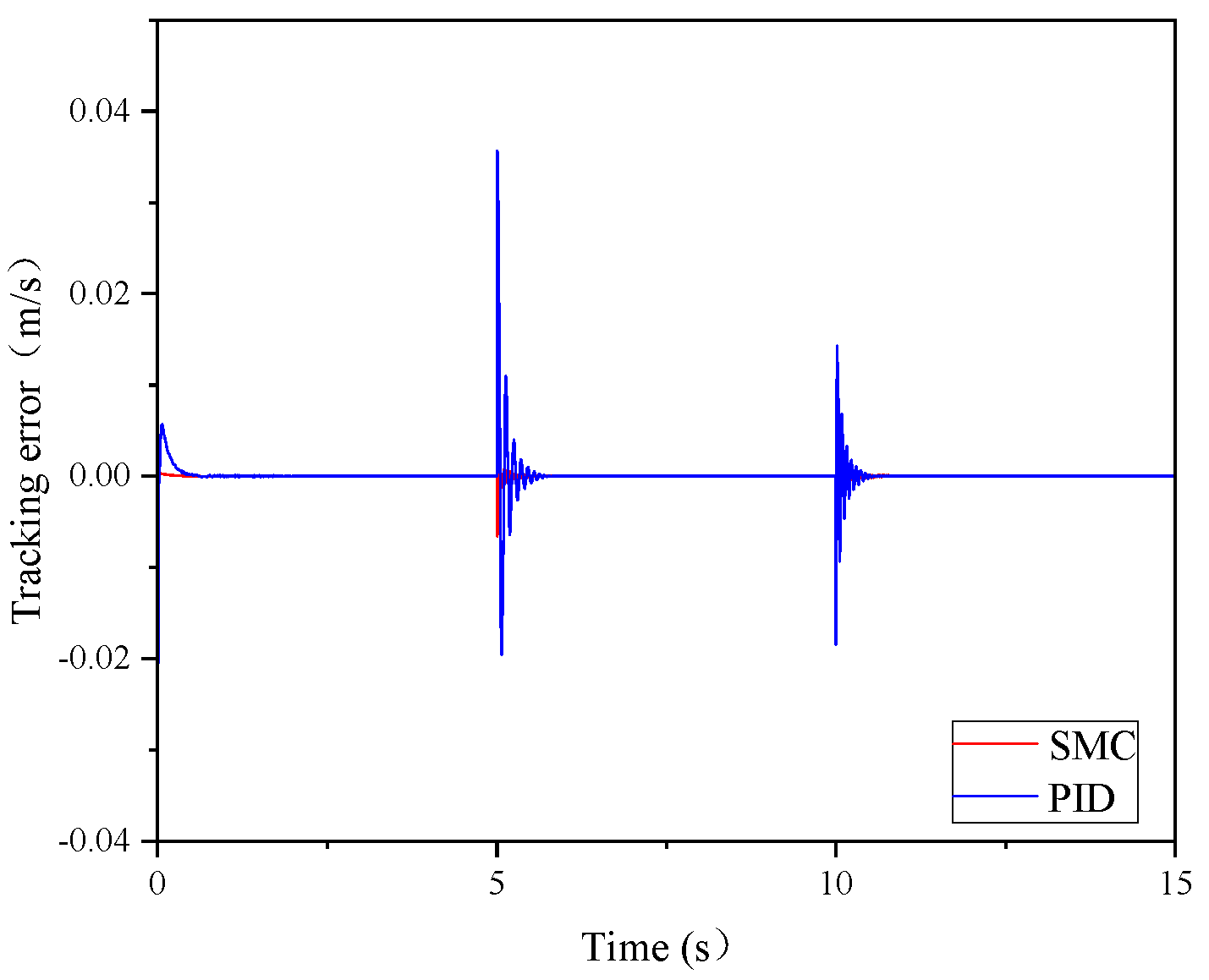
4.2. Feed Rate Control Strategy Based on Sliding Mode Variable Structure Control

When the anti-punching robot performs drilling operations, the diversity of the coal rock properties has a significant impact on its feeding mechanism. The increase in the hardness coefficient of the coal rock, if not accompanied by timely adjustment of the feed speed, will lead to a surge in the amount of coal rock broken per unit in time. When the broken coal rock is not cleaned up in time, problems, such as holding or jamming of the drill, can occur, which will reduce the efficiency of drilling operations. With the frequent changes in coal rock characteristics in underground coal mines, it is especially critical to precisely control the feed speed to ensure that it can be automatically adjusted to the optimal speed according to different load conditions. The relationship between the hardness coefficient of the coal rock and the load resistance is shown in Figure 11.
In the process of feed control, the same process can be used to characterize the changes in coal rock properties with Platt hardness values. The Platt hardness values of 4, 8, and 6 correspond to optimal feed rates of 0.058 m/s, 0.029 m/s and 0.039 m/s, respectively. The simulation time for each condition was 5 s. Figure 12 shows the feed speed control curve and Figure 13 shows the feed speed control tracking error curve.
The simulation results show that there is a significant difference between the control effects of the SMC controller and PID controller. Both controllers have faster response speeds; however, the tracking effect of the PID controller on the desired feed rate under different coal rock hardness coefficients is poorer, there is more overshooting and more errors. In addition, the tracking curve produces a larger jitter when the coal rock hardness is changed abruptly, and the corresponding speed is obviously slower than that of the SMC controller.

5. Experimental Studies

5.1. Drilling System Experiment Platform Construction

The construction of the experimental platform for the anti-punch drilling robot drilling system can be divided into the construction of the hardware and the construction of the software. The hardware construction included sensors, proportional valves, data acquisition cards, controllers, etc., which were connected according to the electrical schematic diagrams. The software construction included the design of the control system, the writing of the control program and control strategy, and so on. The experimental system platform built for this experiment is shown in Figure 14.

5.2. Analysis of Experimental Results

5.2.1. Single Coal Rock Hardness Test

First, the most common rock sandy rock was used as an example; its rock hardness coefficient was determined to be about f = 5. The optimal slewing speed was determined to be 186 r/min and the optimal feed speed was 0.046 m/s. Figure 15 shows the single coal rock hardness slewing control experiment results and Figure 16 shows the single coal rock hardness feed control experiment results.
It can be seen from the experimental results that in the case of a single coal rock hardness of 5 on the Platt hardness scale, the step slewing speed response reaches the optimal slewing speed in 0.43 s, and the step feeding response speed reaches the optimal feeding speed in 0.16 s. After the slewing and feeding speeds reach the optimal speeds, constant speeds for both slewing and drilling are maintained.

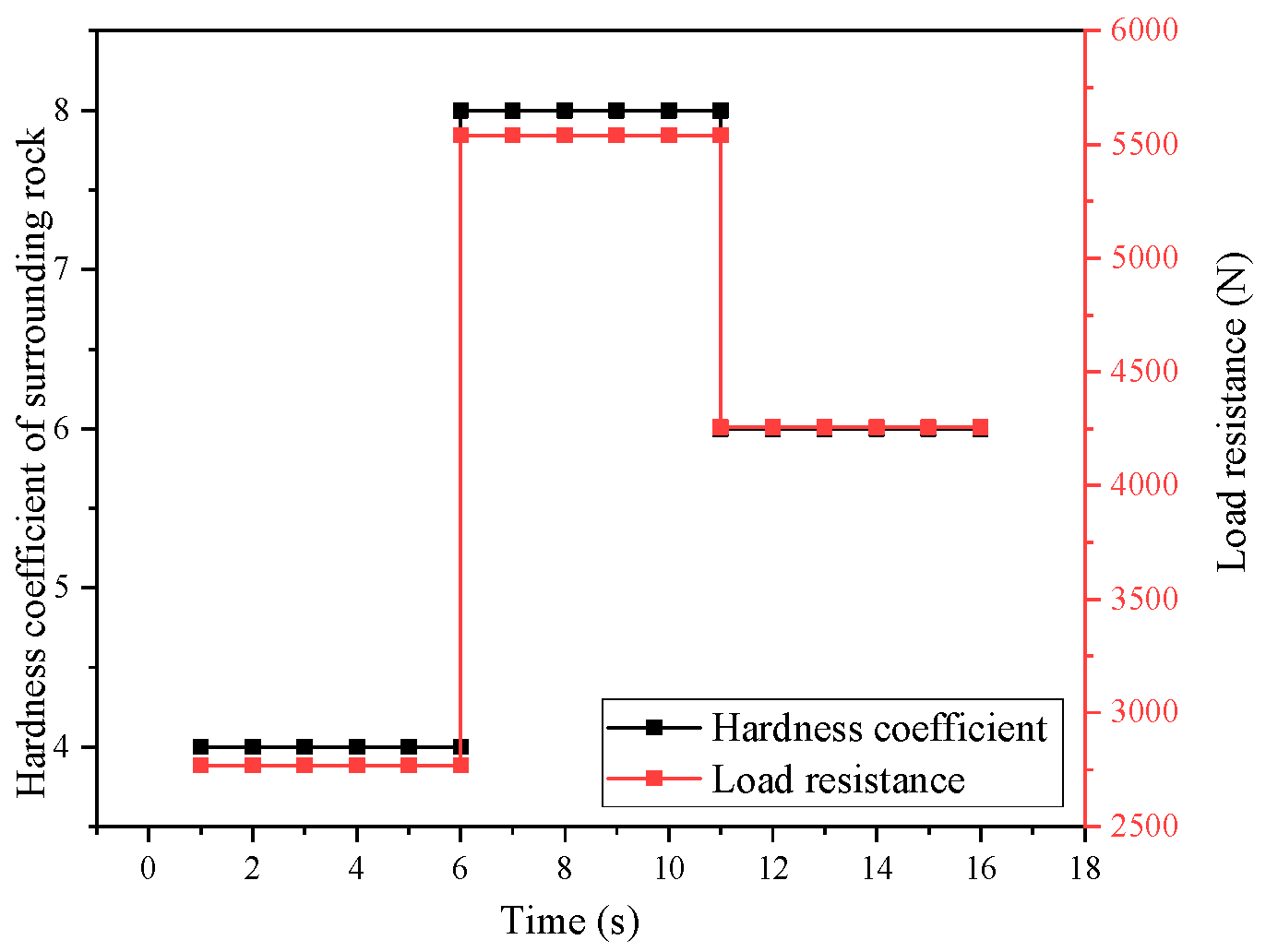
5.2.2. Mutant Coal Rock Hardness Experiment

During the drilling robot drilling process, changes in coal rock hardness occur. For the mutant coal rock hardness experiment, a concrete test block was used with a size of 300 × 300 × 300 mm and a compressive strength of 20 Mpa. Hardness coefficients of 4, 8, and 6, respectively, were used to simulate the drilling process during coal rock mutations. Figure 17 shows the mutant coal rock slewing control experiments and Figure 18 shows the mutant coal rock feed control experiments.
Under the control of the ADRC controller and SMC controller, the drilling system automatically matched the optimal slewing speed and feed rate when changes in the hardness of the test block were encountered. The response speed was faster. When the optimal feed rate and slewing rate were reached, the state of the system was more stable, with good robustness. The experimental results showed that the control strategy designed in this paper can meet actual control requirements.

6. Conclusions

(1)
By analyzing the structure of the anti-punch drilling robot and the drilling system, the workflow of system with respect to the drilling function and the cooperation relationship between the actuators was clarified and the optimal slewing speed and feed speed in the drilling process were determined through an analysis of the drilling rod force;
(2)
Combined with the drilling process and the working characteristics of each actuator, a control strategy for the drilling control system was proposed. A slewing control strategy based on a self-immunity control algorithm and a feed control strategy based on sliding mode variable structure control were designed. Based on the drilling system, a physical model was established in AMESim software and a mathematical model was established in Simulink software. A joint simulation was carried out, and the control performance and control effects of each controller were analyzed through the joint simulation;
(3)
The construction of the drilling robot drilling electrohydraulic control system experimental platform was completed by using different hardness coefficients of concrete specimens to simulate the hardness of different coal rock traits. Single coal rock hardness experiments and drilling experiments with sudden changes in coal rock hardness were conducted. The experimental results showed that the control strategy proposed in this paper meets the requirements needed to control the drilling system.

Author Contributions

Methodology, B.L.; Resources, G.L.; Writing—original draft, B.L.; Writing—review & editing, G.L. and G.S.; Funding acquisition, B.L. and G.L. All authors have read and agreed to the published version of the manuscript.

Funding

Project supported by the National Key Research and Development Program of China (No. 2023YFC2907400), and Jiangsu Qinglan Project.

Data Availability Statement

Data are contained within the article.

Conflicts of Interest

Author Guang Li was employed by the company Changsha Mine Research Institute Co., Ltd. The remaining authors declare that the research was conducted in the absence of any commercial or financial relationships that could be construed as a potential conflict of interest.

References

  1. Wang, Z.; Si, L.; Wang, H.; Zhang, X.; Zhao, S.; Wei, D.; Tan, C.; Yan, H. Position solving method for anti-punch drilling robot based on spatial arrayed inertial unit. J. Coal 2022, 47, 13. [Google Scholar]
  2. Niu, C. Research on Drilling Control of Tooth Wheel Drilling Rig. Master’s Thesis, Jilin University, Changchun, China, 2017. [Google Scholar]
  3. Wang, G. Accelerating the construction of coal mine intelligence to promote the high-quality development of coal industry. China Coal 2021, 47, 2–10. [Google Scholar]
  4. Ge, S.; Hu, R.; Pei, W. Coal mine robot system and key technologies. J. Coal 2020, 45, 455–463. [Google Scholar]
  5. Hu, Z.; Sun, Y. Design and test of drilling control simulation system and control algorithm. Coal J. 2009, 34, 455–460. [Google Scholar]
  6. Zhao, X.Y. Control Algorithm Analysis of Rig’s Electro-Hydraulic Proportional Control System. Appl. Mech. Mater. 2013, 423–426, 2837–2840. [Google Scholar] [CrossRef]
  7. Wang, Q.; Chen, H.; Chen, Y. Research on intelligent sensing and adaptive control mechanism of drilling robot for drilling working conditions. Min. Saf. Environ. Prot. 2021, 48, 1–5. [Google Scholar] [CrossRef]
  8. Zhao, J.; Liang, P.; Liu, Q.; Han, S.; Zhang, Y. Control algorithm of weight on bit and rate of penetration based on drilling robot. Proc. Inst. Mech. Eng. Part E J. Process Mech. Eng. 2022, 237, 2557–2566. [Google Scholar] [CrossRef]
  9. Cavanough, G.L.; Kochanek, M.; Cunningham, J.B.; Gipps, I.D. A Self-Optimizing Control System for Hard Rock Percussive Drilling. IEEE/ASME Trans. Mechatron. 2008, 13, 153–157. [Google Scholar] [CrossRef]
  10. Shi, F.; Li, L.; Zhang, Q.Z.; Rasol, N. Derivative and Integral Sliding Mode Control for Rotary Drilling System. In Proceedings of the Third International Conference on Measuring Technology & Mechatronics Automation, Shanghai, China, 6–7 January 2011; IEEE Computer Society: Washington, DC, USA, 2011. [Google Scholar]
  11. Haber, R.E.; del Toro, R.M.; Gajate, A. Optimal fuzzy control system using the cross-entropy method. A case study of a drilling process. Inf. Sci. 2010, 180, 2777–2792. [Google Scholar] [CrossRef]
  12. Kremers, N.A.H.; Detournay, E.; Van De Wouw, N. Model-Based Robust Control of Directional Drilling Systems. IEEE transactions on control systems technology: A publication of the IEEE Control Systems Society. IEEE Trans. Control Syst. Technol. 2016, 24, 226–239. [Google Scholar] [CrossRef]
  13. Inyang, I.J.; Whidborne, J.F. Bilinear Modelling, Control and Stability of Directional Drilling. Control Eng. Pract. 2018, 82, 161–172. [Google Scholar] [CrossRef]
  14. Georgiou, A.; Evangelou, S.A.; Jaimoukha, I.M.; Downton, G. Tracking Control for Directional Drilling Systems Using Robust Feedback Model Predictive Control. In Proceedings of the 21st IFAC World Congress, Berlin, Germany, 11–17 July 2020. [Google Scholar]
  15. Laib, A.; Talbi, B.; Krama, A.; Gharib, M. Hybrid Interval Type-2 Fuzzy PID+I Controller for a Multi-DOF Oilwell Drill-String System. IEEE Access 2022, 10, 67262–67275. [Google Scholar] [CrossRef]
  16. Kong, X.Z.; Jiang, S.Y.; Li, Y.B. Intelligent hybrid control of the pneumatic proportional system. Chin. J. Mech. Eng. 2009, 45, 84–88. [Google Scholar] [CrossRef]
  17. Li, D.; Ma, G.; Li, J. Four-point dynamic leveling method for drilling platform application. Assem. Autom. 2021, 41, 46–77. [Google Scholar] [CrossRef]
  18. Liu, F.C.; Jia, X.Q.; Liu, L. Pneumatic loading system modeling and nonlinear active disturbance rejection control. Control Decis. 2017, 32, 906–912. [Google Scholar]
  19. Buckstegge, F.; Michel, T.; Zimmermann, M.; Roth, S.; Schmidt, M. Advanced Rock Drilling Technologies Using High Laser Power. Phys. Procedia 2016, 83, 336–343. [Google Scholar] [CrossRef]
  20. Li, X.; Zhou, Z.; Ye, Z.; Ma, C.; Zhao, F.; Zuo, Y.; Hong, L. Mechanical characterization of rocks loaded by dynamic-static combination. J. Rock Mech. Eng. 2008, 27, 1387–1395. [Google Scholar]
  21. Yu, C.X. Research on the Dynamic Characteristics of Drill Pipe of TBM Machine-Mounted Anchor Drilling Rig. Master’s Thesis, East China Jiaotong University, Nanchang, China, 2020. [Google Scholar]
  22. Lian, C.; Sun, C.; Xiao, Y. Research on the position synchronization control of two cylinders based on self-immunity control. Mach. Tools Hydraul. 2024, 1–11. [Google Scholar]
  23. Wang, L.X.; Zhao, D.X.; Liu, F.C.; Meng, F.L.; Liu, Q. Self-impedance control of electro-hydraulic proportional servo force loading. J. Mech. Eng. 2020, 56, 216–225. [Google Scholar]
  24. Ren, L.; Cui, J.; Sun, Y.; Cheng, X. Multi-bearing remaining useful life collaborative prediction: A deep learning approach. J. Manuf. Syst. 2017, 43, 249–256. [Google Scholar] [CrossRef]
  25. Xiao, X. Research on fuzzy sliding mode variable structure control of hydraulic servo system. Sci. Technol. Innov. 2021, 6, 18–20. [Google Scholar]
  26. Chen, C. Characterization of Electro-Hydraulic Servo System and Design of Sliding Mode Variable Structure Controller. Master’s Thesis, Taiyuan University of Science and Technology, Taiyuan, China, 2014. [Google Scholar]
Figure 1. Drilling system components.
Machines 13 00133 g001
Figure 2. Working process of drilling system.
Machines 13 00133 g002
Figure 3. Drill pipe space motion relationship.
Machines 13 00133 g003
Figure 4. Force analysis of drill bit.
Machines 13 00133 g004
Figure 5. Drilling system control strategy.
Machines 13 00133 g005
Figure 6. Block diagram of the self-immunity control algorithm.
Machines 13 00133 g006
Figure 7. Joint simulation model.
Machines 13 00133 g007
Figure 8. Curve of hardness factor vs. load torque.
Machines 13 00133 g008
Figure 9. Rotation speed control curve.
Machines 13 00133 g009
Figure 10. Tracking error curve of rotary speed control.
Machines 13 00133 g010
Figure 11. Curve of hardness coefficient versus load resistance.
Machines 13 00133 g011
Figure 12. Feed speed control curve.
Machines 13 00133 g012
Figure 13. Feed rate control tracking error curve.
Machines 13 00133 g013
Figure 14. Drilling system experiment platform.
Machines 13 00133 g014
Figure 15. Results of single coal rock hardness rotary control experiment.
Machines 13 00133 g015
Figure 16. Experimental results of single coal rock hardness feed control.
Machines 13 00133 g016
Figure 17. Experimental results of mutant coal rock slewing control.
Machines 13 00133 g017
Figure 18. Experimental results of mutant coal rock feed control.
Machines 13 00133 g018
Table 1. Optimal control parameters for coal rocks with different Platt hardness coefficients.
Hardness FactorOptimum Speed (r/min)Load Torque (N-m)Optimum Feed Speed (mm/s)Feed Force (N)
3309243772078
4232324582770
5186405463463
6154486394256
7132567334848
8116648295541
Disclaimer/Publisher’s Note: The statements, opinions and data contained in all publications are solely those of the individual author(s) and contributor(s) and not of MDPI and/or the editor(s). MDPI and/or the editor(s) disclaim responsibility for any injury to people or property resulting from any ideas, methods, instructions or products referred to in the content.

