Abstract
With the increase in reliance on doubly fed induction generator-based wind energy conversion systems (DFIG-WECSs), extracting maximum power from wind energy and enhancing fault ride-through (FRT) techniques meeting the grid code requirements is the foremost concern. This paper proposes a modified control scheme that operates in normal running conditions and during faults as a dual mode. The proposed control scheme operates in a coordinated wind speed estimation-based maximum power point tracking (WSE-MPPT) mode during normal running conditions to extract maximum power from wind energy and enhances the crowbar rotor active impedance-based FRT mode during faults. The proposed technique controls the rotor side converter (RSC) parameters during faults by limiting the transient surge in the rotor and stator currents. In this study, the transient behavior of the proposed technique is analyzed under a three-phase symmetrical fault with a severe voltage dip, and it is observed that, when the fault is over and the RSC is activated and connected to the system, a large inrush current is produced with transient oscillations; the proposed scheme suppresses this post-fault inrush current and limits the transient oscillation. During the FRT operating mode under a symmetrical fault, the simulation results of the proposed technique are validated by the conventional crowbar strategy. In contrast, during the WSE-MPPT operating mode under normal running conditions, a smooth achievement of system parameters after starting the inrush period to a steady state at fixed wind speed is observed.
1. Introduction
With the growing shift towards wind power, integrating large-scale wind energy generation on the power grid has become very important. The doubly fed induction generator (DFIG) and permanent magnet synchronous generator (PMSG) are the most favored wind generators among large-scale wind energy generation systems. PMSGs have the advantages of low maintenance costs because of the absence of a gearbox, more reliability and durability due to the elimination of gearbox and bearings, and ease of control due to the variable-speed drive converter. However, PMSGs have multiple disadvantages, such as high costs due to a fully rated converter, the requirement for a permanent magnet, which makes PMSG more expensive, and the fact that a multipole generator increases the size of the machine [1]. Another problem associated with PMSGs is encountered during starting, due to their synchronous property, which requires constant voltage [2].
On the other hand, DFIG-based wind energy systems have become a pivotal technology in modern power grids. DFIGs are favored in wind power generation due to their efficient power control capabilities and ability to operate at varying wind speeds; 25–30% of the rated power is controlled through a rotor side controller, which requires low-rated converters, smaller in size [3]. However, the primary concern of DFIGs is the extraction of maximum power from wind energy during normal running conditions and their integration into the grid, particularly in terms of fault ride-through (FRT) during fault conditions. A significant body of research has emerged focusing on enhancing the stability, maximum power extraction, and fault tolerance of DFIG-based wind turbines to ensure they meet grid code requirements, maintain reliability, and provide continuous energy during grid disturbances and normal running conditions [4].
Many MPPT techniques have been proposed to increase efficiency and extract maximum power from the wind, such as wind speed estimation (WSE), tip speed ratio (TSR), and perturbation and observation (P&O). The TSR-based MPPT technique proposed by Abdel Raheem et al. use an anemometer to find the wind speed, but this method is costly and requires regular maintenance [5]. Mousa Hossam et al. proposed an efficient P&O technique that accurately tracks wind power, but the major disadvantage is low tracking speed [6]. To overcome these drawbacks in TSR and P&O, a novel WSE-based MPPT technique is proposed by Jiao et al. to achieve maximum wind power with quick rotor tracking speed and low-cost implementation [7].
When a fault occurs in a grid-connected DFIG-based wind system, the transient currents in the rotor and stator winding reduce the life span of the wind system and may damage the RSC and grid side converter (GSC). Researchers propose many fault ride-through FRT techniques to protect the RSC and GSC from transient currents and voltage dips during grid faults while meeting grid code requirements. A new fault current limiter device is designed to improve the fault tolerance of DFIG-based wind turbines. This device limits the effects of transient currents during grid faults, increasing the system stability and improving the overall grid resilience during fault conditions [8]. A detailed discussion on understanding DFIG dynamics, control, and its integration to the grid, based on different frequency domain and state space strategies, is presented in [9]. Kaloi et al. present a novel approach to control the active and reactive power using suitable voltage vectors on the RSC of DFIG-based systems [10]. A novel fault ride-through technique that uses dynamic voltage restorers in DFIG-based wind turbines to maintain operation during a grid voltage dip is discussed in {11}. This technique ensures that turbines stay connected to the system despite voltage fluctuations, thus enhancing performance and fault tolerance [11]. A new energy storage integrated system has proven to be an enhanced strategy for improving wind turbines’ reliability and fault tolerance. Shen et al. proposed a modified auxiliary control method for energy storage devices, which provides fault current support to DFIG-based WTs. This research discusses energy storage devices’ central role in supporting DFIG-based WTs during grid faults, allowing for smoother voltage regulation and improved grid stability [12]. To further improve the fault ride-through (FRT) capabilities of DFIG-based WT systems, Souza, Barros, and Costa introduce a modular multilevel converter. This converter helps DFIG systems withstand voltage dips and maintain grid stability during low-voltage conditions, significantly enhancing the system’s performance and limiting the fault current. [13]. Additionally, Vinoth Kumar and Selvan propose a novel technique that enhances the fault ride-through capabilities of DFIG-based wind turbines. This approach increases system reliability during faults and ensures continuous energy production under grid disturbance conditions [14].
In another novel work, Rahimi et al. proposed enhanced fault ride-through DFIG-based wind turbine techniques during balanced faults. Analytical expressions are developed to examine the rotor current and rotor voltage behavior. Their study provides a detailed discussion of the RSC and DC-link voltage control strategy that allows DFIG-based wind turbines to ride through grid disturbance [15]. Dai et al. also contribute to low-voltage ride-through by introducing a modified DC-link current control strategy to protect the GSC and RSC converters, further enhancing the LVRT capabilities of DFIG systems and ensuring stable performance under low-voltage conditions [16]. Yang et al. propose an enhanced control strategy for DFIG-based wind turbines, which improves fault ride-through capabilities by effectively handling the grid disturbance and overall system parameters. [17]. Sami et al. proposed an artificial neural networks-based sliding mode control scheme, leading to enhanced convergence speed and improved fault tolerance in DFIG-based wind systems [18].
In recent years, many novel approaches have been developed for multi-port conversion systems to predict performance in frequent operation circumstances. The dynamic impact of grids with high power electronics content in renewable energy sources weakens the nearby AC grids [19], and this causes resonance between the power equipment and control systems; therefore, the tuning control of the parameters through a suitable controller is always a matter of concern [20,21]. The decoupled operation of active and reactive power through various controllers like the PI controller, the slide mode controller, and the fuzzy logic controller has been undergone in [22,23,24]. Among the existing controllers in the literature, the PI controller is most widely employed due to its simplifications. In contrast, the proportional resonance (PR) controller is employed under unbalanced faults [25], and the dependency of the (PR) controller in frequency changes is discussed in [26]. A novel control strategy for tuning proportional controllers based on a diverse fractional order approach in a weak AC grid scenario is discussed in [27]. An advanced control strategy proposed by Chehaidia et al. introduced a fuzzy gain scheduling of the PI controller that controls the electromagnetic torque to capture maximum power from variable-speed wind turbines.
The proposed study ensures that the wind turbine operates optimally under different wind conditions while maintaining grid stability [28]. Nouriani et al. present a comparative study of different LVRT-based control methods for variable-speed wind turbines, which provides a detailed understanding of multiple approaches to enhance grid stability and fault tolerance in wind energy systems [29]. With the increase in wind turbine-based energy generation, the need for frequency stability becomes a foremost concern. Kazemi Golkhandan et al. present a control strategy designed to improve the frequency stability in power systems with high wind-power penetration. Their work focused on the importance of DFIG-based wind turbines in maintaining grid stability [30]. Shahbazi et al. investigate real-time experimental fault analysis and fault-tolerant operation in DFIG-based systems. Their study ensures that DFIG systems can remain connected with the grid while operating reliably even in component faults [31]. Chojaa et al. analyzed nonlinear control techniques to enhance the performance of DFIG during varying wind conditions. Their research contributes to the development of a more reliable control method that controls the system parameters during the fluctuating nature of wind energy, ensuring system stability [32]. Almozayen et al. further examine DFIG-based WECS behavior under three-phase symmetrical fault conditions using the dynamic phasor finite element method. This study analyzes the production and method of the harmonics to minimize their effects on system parameters, providing an enhanced controlled model during grid disturbances [33].
In recent work, Kang et al. proposed a zero-voltage ride-through strategy for permanent magnet synchronous generator PMSG-based wind systems. Their method is based on nonlinear extended state observers and sliding mode control, highlighting a novel approach to maintaining system performance during zero-voltage conditions [34]. Bekiroglu et al. present a crowbar protection scheme to enhance the fault ride-through capability of DFIG-based systems during symmetrical and asymmetrical fault current and voltage dips, offering a novel control method to protect rotor side controller RSCs from the fault current and ensure continuous power generation during faults [35]. Kaloi et al. and S.B Naderi et al. proposed an enhanced fault ride-through technique by using a feedback linearization control method and DC chopper to control the DC link voltage, rotor, and stator current during grid faults [36,37]. Most of the literature discussed has worked on limited system parameters, and very minimal literature is available on the synchronized mode of operation to operate under normal running conditions with a maximum power extraction approach and under fault and post-fault conditions as fault current protection approaches simultaneously. This paper deals with the steady state, dynamic, and transient condition analysis of grid-connected DFIGs.
The main novelty of this paper is working in a synchronized mode of operation with an enhanced crowbar-based rotor active impedance control strategy under the FRT mode and switching to wind speed estimation-based WSE-MPPT to extract the maximum wind power under normal running conditions. During the FRT mode, it is observed that the transient appears two times on the rotor side, firstly during the fault and secondly after the fault because of RSC activation; using the active impedance with the controller can reduce the post-fault inrush current. In this study, three approaches are used; firstly, an analytical expression is developed to investigate the rotor and stator dynamics under a severe voltage dip in symmetrical fault conditions to determine the proper crowbar resistance that reduces the severity of the fault. Secondly, an active impedance is used with an RSC to reduce the post-fault inrush current when the crowbar is deactivated. Thirdly, a synchronized WSE-MPPT approach is developed under normal conditions. The proposed approach accurately represents the system’s behavior under fault conditions and improved control over transient currents, leading to more robust FRT performance and enhanced system stability.
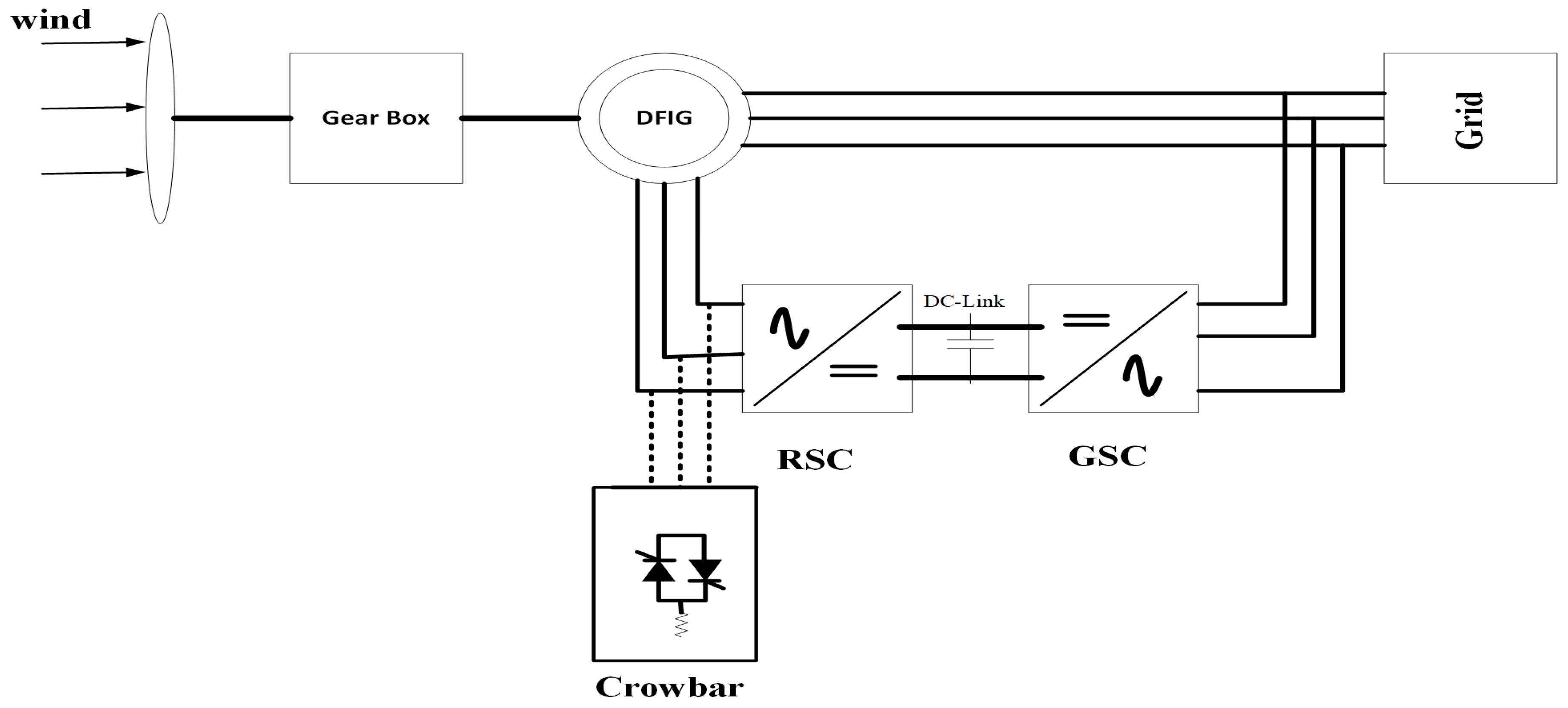
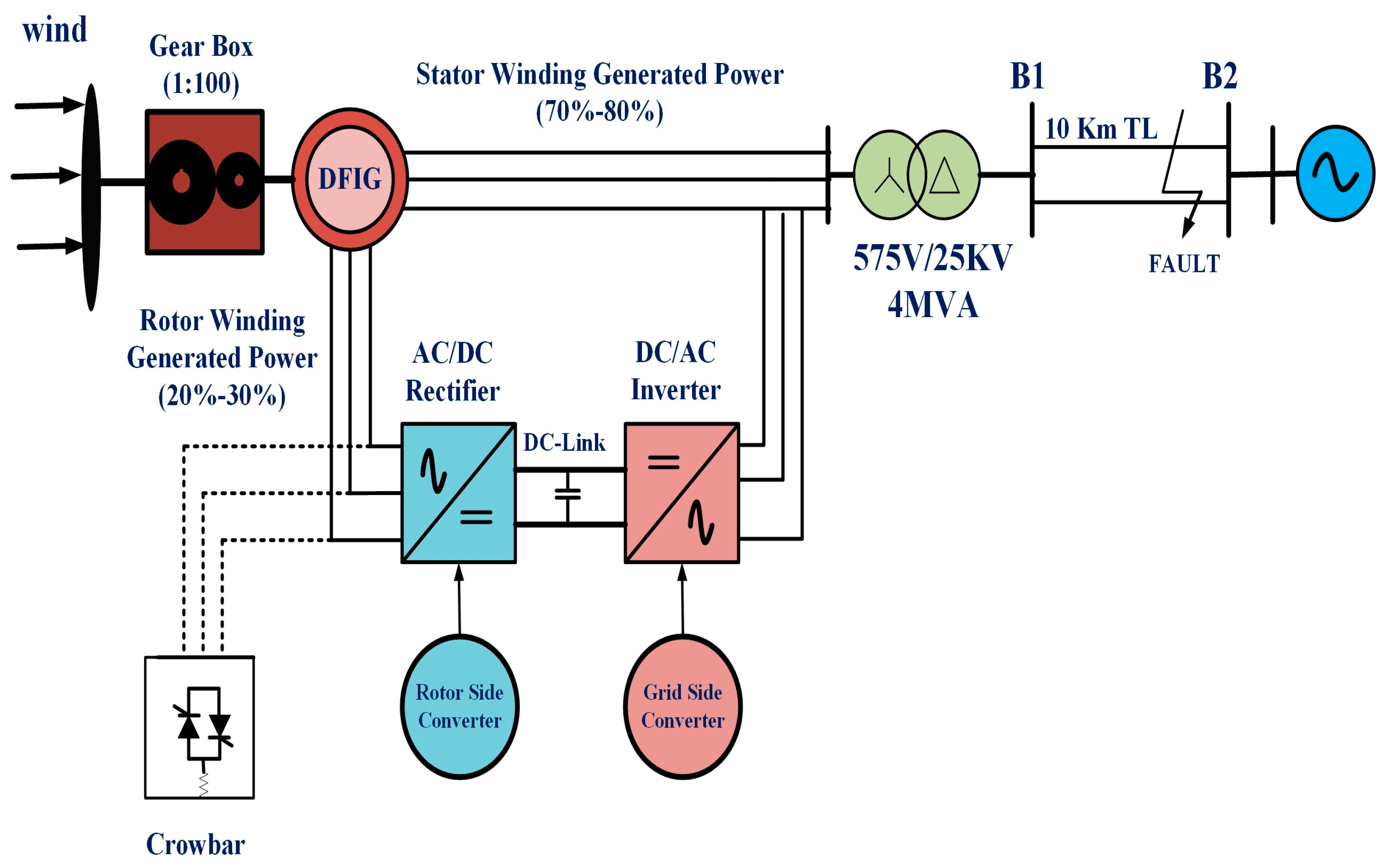
The general functioning of a DFIG-based-WT with crowbar protection is shown in Figure 1. It shows the essential components of the DFIG-WT, which consists of gearbox, rotor side, and, grid-side, two bi-directional converters connected via DC bus and an RL filter and crowbar used to protect the RSC during faults.
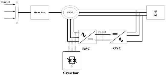
Figure 1.
Schematic diagram of DFIG-based wind turbine with crowbar protection.
2. Proposed FRT-Based Modeling of Rotor and Stator
The proposed control scheme has a dual mode of operation. During a fault, it switched to the FRT mode of operation. This section deals with stator and rotor transient modeling to calculate the fault currents and voltage dip in the DFIG. The value of stator and rotor parameters are determined in d-q axes, which are DC components, in a synchronous reference frame.
where denote d-q axis stator and rotor voltages, respectively, whereas represent stator and rotor flux, respectively. are the rotor resistance, synchronous speed, stator resistance, and slip, respectively [38,39].
Equation (5) is achieved by placing the value of Equation (4) into Equation (2)
d-q axis stator current, as shown in Equation (6), is obtained from rearranging Equation (3)
d-q axis rotor voltage, as shown in Equation (7), is obtained by relating the above Equations (4)–(6).
The back EMF voltage induced in the rotor, which is the function of stator flux and current, as shown in Equation (8), is used to find the rotor transient currents during the fault, representing the effect of stator dynamics on rotor dynamics.
d-q axes rotor current, as shown in Equation (9), is achieved by isolating rotor current from Equation (4).
By isolating and simplifying the d-q axis rotor current and from Equation (5), then putting the and values in Equation (3), d-q stator flux and is obtained as shown below in Equation (10).
The above equation shows dynamic modeling of stator flux linkage in d-q axes where the term is the transient reactance, which can be represented as , and Equation (10) can be re-written as Equation (11):
During fault analysis, the effects of the transient behavior of stator voltage on rotor dynamics are obtained by including the stator transient flux from Equation (11) into Equation (1), and, by neglecting the flux linkages derivation and , we obtain Equation (12).
The source voltage and is the residual voltage in the machine, and it is necessary to calculate the source voltage because it shows transient behavior. It can be calculated by incorporating Equation (9) into Equation (2), as shown below [40,41].
where represents the transient inductance of rotor dynamics.
d-q axis rotor voltage during fault is obtained by putting the stator current as in Equation (6) and its derivative in Equation (5) and simplifying the equation; the authors obtain the following:
where the stator flux and is a rotating vector of constant amplitude that rotates at a synchronous speed . and are the rotor back emf parameters because of stator flux and can be represented as and .
The transient behavior of d-q axis rotor voltage and stator flux is shown in Equations (15) and (16).
where and shows the rotor transient resistance and inductance [41]. Equation (16) shows the change of d-q axis stator flux during a fault and after a fault, and represents the stator flux damping.
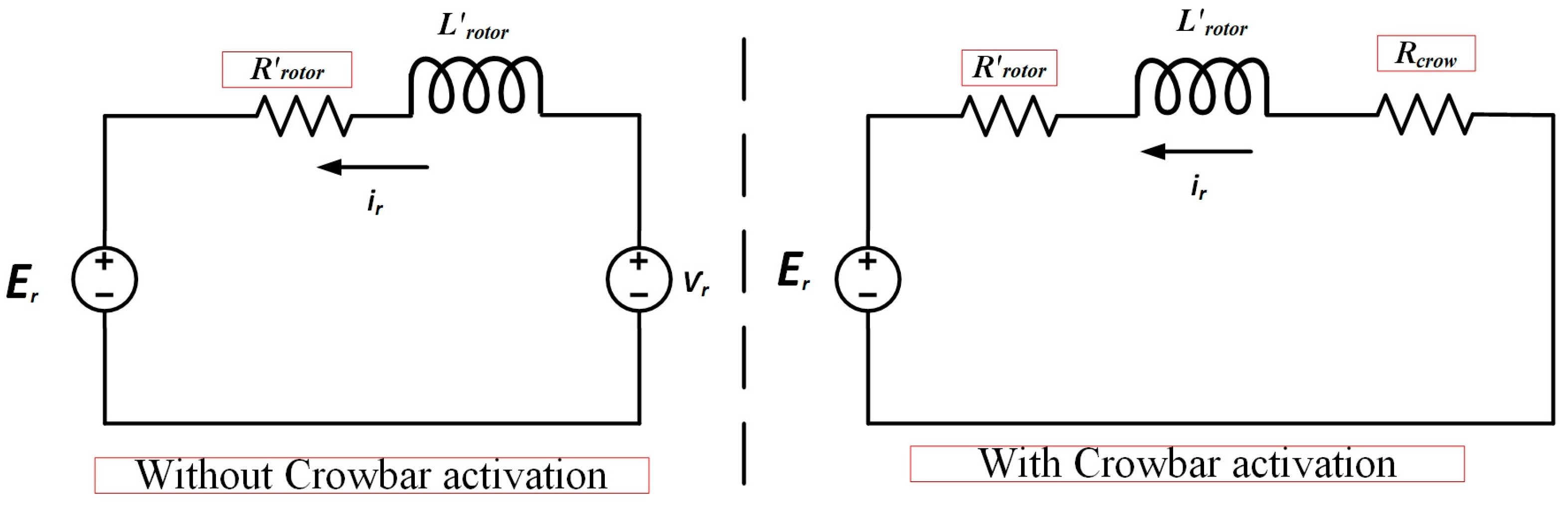
Equations (15) and (17) represent the rotor fault current equations with and without crowbar activation. The equivalent rotor transient diagram during a fault is shown in Figure 2 below. When the crowbar activates during the fault, RSC is deactivated, and the rotor voltage becomes zero, as shown in Equation (17):
where shows crowbar resistance during the fault; and are the back emf voltage induced in the rotor due to stator flux.
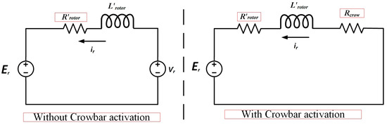
Figure 2.
Equivalent circuit diagram of the rotor during a fault.
Equation (19) shows the rotor current during an unsymmetrical fault when the crowbar activates, which is obtained by comparing the Equations (17) and (18), as follows:
Here, the value of is low when compared with rotor damping; is intended to equal to 1. For the worst case of a three-phase short circuit fault (symmetrical fault), and will become zero, and Equation (19) can be rewritten as
The optimal value of crowbar resistance while keeping the input line voltages (VL) of the crowbar below the dc-link voltage (Vdc) is computed as Rcrow = 0.17 p.u = 26Rrotor.
3. MPPT Modeling of Rotor Side Converter Control
The proposed control scheme limits the surge in rotor currents during faults with enhanced FRT-based active impedance crowbar protection and switches to MPPT under normal running conditions. Maximum power extraction is achieved by wind speed estimation based on the maximum power point tracking WSE-MPPT method through the rotor side converter (RSC) control. The fuzzy-based algorithm is developed in normal grid conditions to extract the maximum wind power. The proposed control scheme is designed to operate in a dual mode efficiently during normal running conditions by applying the MPPT technique and enhanced FRT technique during faults to protect the RSC from the fault current.
The mechanical power output from the wind turbine [42] is given as
where represents the density of air, shows the wind speed, and R shows the blade radius of the turbine.
The wind speed is obtained from the measured value of rotor speed , the radius of turbine rotor R, and the tip speed ratio , as shown in Equation (22)
The rotor reference speed, , is achieved from the value of wind speed and tip speed ratio as shown in the equation below:
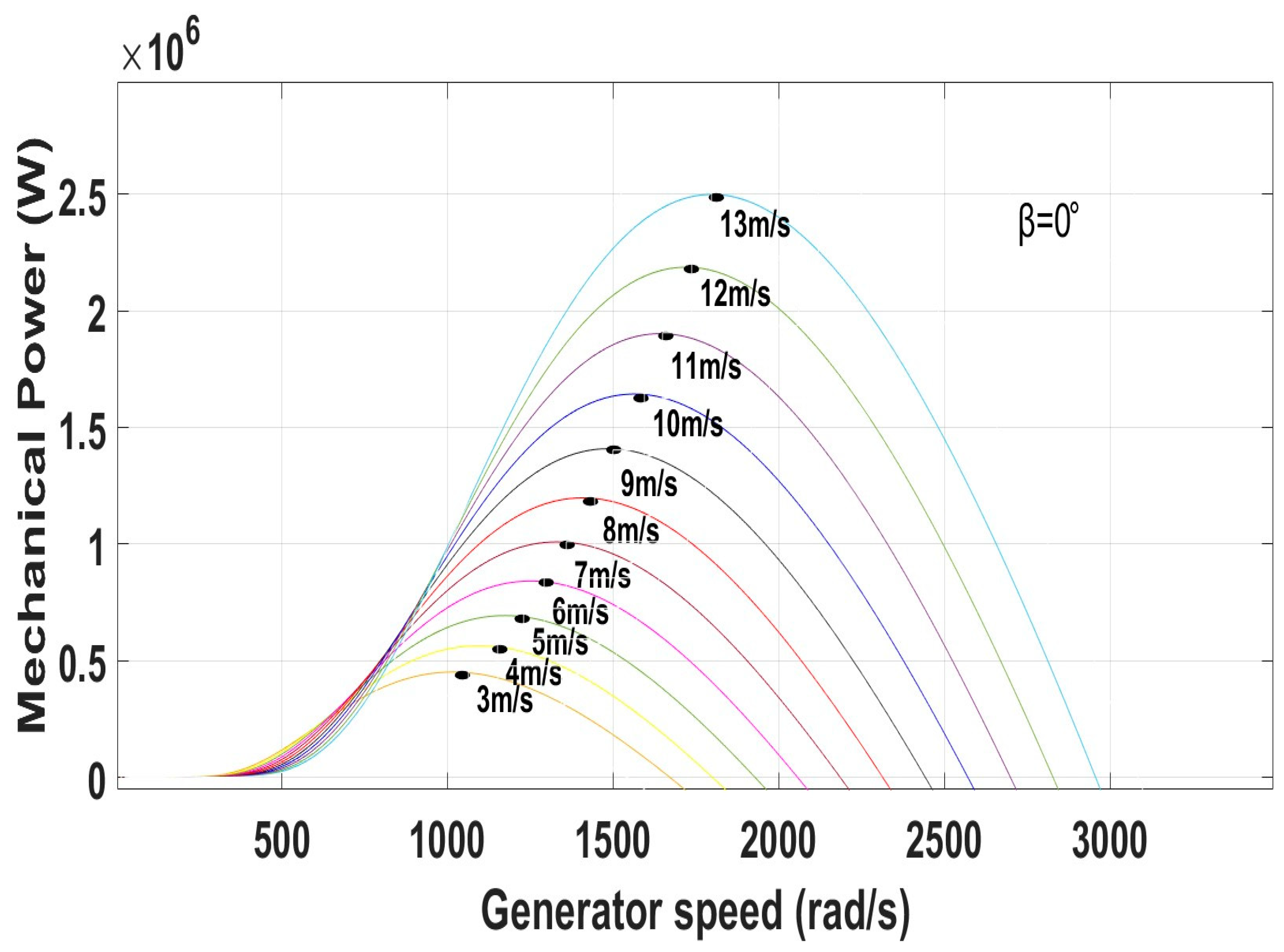
To obtain the maximal power extraction at each wind velocity of rotor speed, as shown in Figure 3, it should be of maximal value at .

Figure 3.
Characteristics of wind turbines under different wind speed conditions.
The rotor speed error is calculated from the measured rotor speed and rotor reference speed as shown below.
The direct axis rotor current under normal running conditions is generated by a C.R Raghavendra [43]-based fuzzy logic controller, whereas the input of fuzzy logic is rotor speed error and change in rotor speed error .
The mechanical power output changes with the change in the speed of the wind; the wind turbine achieves the maximum rated speed using the maximum power tracking technique when the value of pitch angle is , as shown in Figure 3. To obtain the maximal power extraction at each wind velocity of rotor speed, the value of should be maximum.
4. Proposed Control Scheme of the Rotor Side Converter
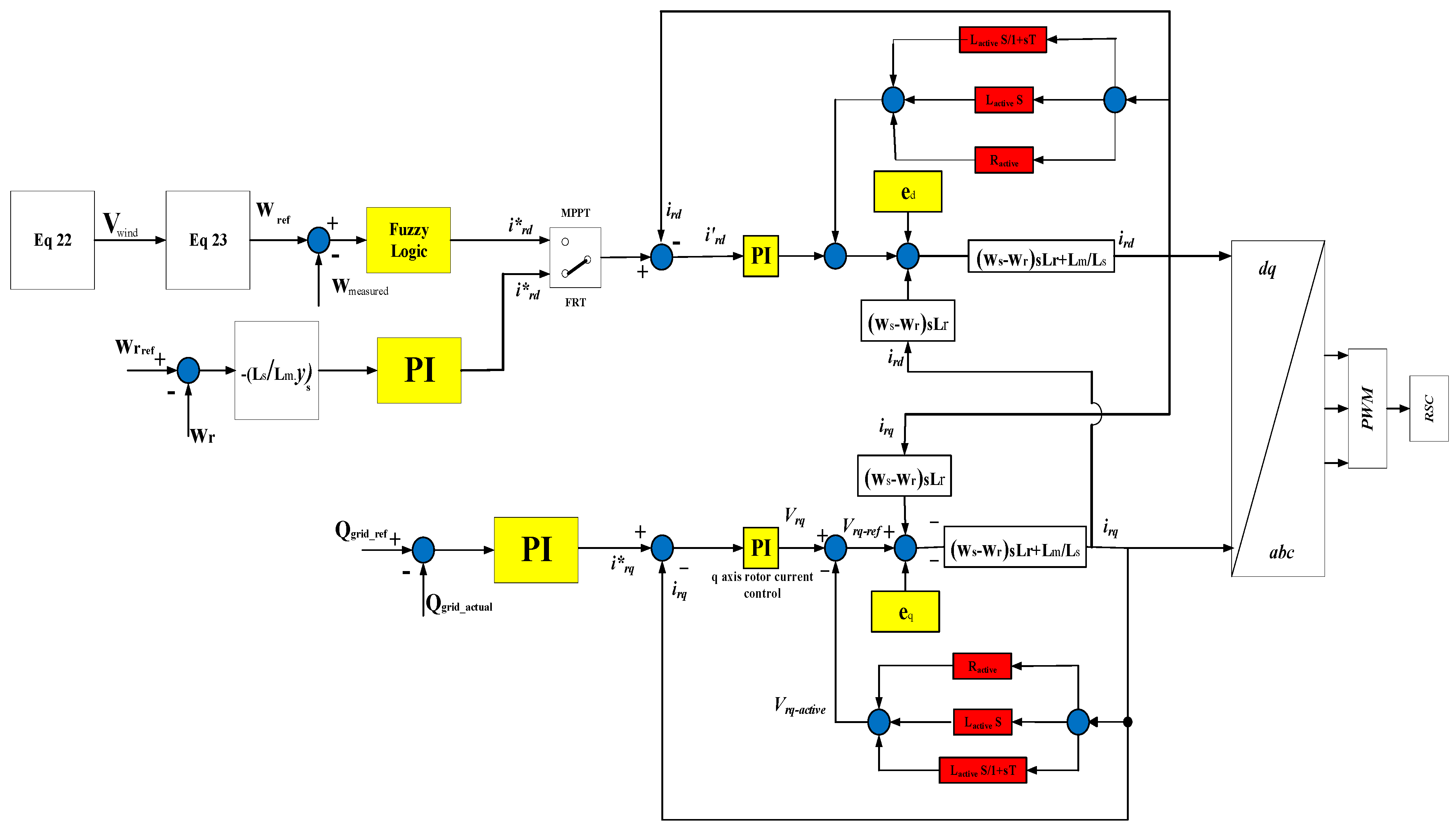
The proposed RSC control scheme is suitable for operating in normal running conditions and during faults. This dual mode of operation is based on a coordinated control scheme. During normal running conditions, the MPPT fuzzy-based technique extracts maximum power from the wind turbine through RSC control. The proposed scheme switches over to the FRT mode when the fault occurs, and active impedance-based crowbar control is activated, as shown in Figure 4. During the FRT mode, the main objective is to minimize fault current to protect the RSC from overcurrent. The conventional crowbar protection scheme is insufficient to minimize the fault currents to an acceptable level. The active impedance-based crowbar protection limits the transient current to an admissible level, reduces the transient oscillations, and limits the post-fault inrush currents.
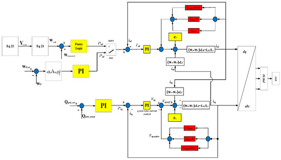
Figure 4.
Proposed modified rotor current control scheme.
During normal running conditions, the proposed MPPT mode is activated and generated as shown below.
The proposed modified FRT mode is activated during fault conditions, and the MPPT mode is deactivated, as shown below.
The rotor’s active impedance is obtained by subtracting an active control voltage. from the output of the controller . Therefore, the output reference voltage can be written as
5. Test System Under Simulation Study with FRT Mode
Figure 5 shows the test system under study, which consists of a 2 MW DFIG-based wind turbine linked to the utility grid, with the constant wind speed identified as 12 m/s. The power is supplied through a 575 V Y/25 kV , 4 MVA transformer connected with a double circuit of a 10 km long transmission line. The three-phase symmetrical fault is applied between points B1 and B2. The fault occurs for a period of 0.3 s between . The parameters of the DFIG are shown in Table 1.
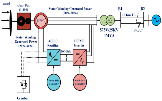
Figure 5.
DFIG-based wind turbine under simulation study with fault.

Table 1.
DFIG parameters.
6. Results, Comparison, and Discussion
This section analyzes the performance of a grid-connected DFIG in WSE-MPPT and FRT mode using the MATLAB/Simulink (R2022b) tool. A comprehensive model has been developed to analyze the performance of the DFIG under steady state and dynamic conditions. The proposed control scheme is compared with the conventional protective technique to demonstrate the system behavior under severe three-phase faults. In addition, the system performance is also observed after a fault when the crowbar is deactivated, which causes rotor inrush current in the conventional protective scheme. With the help of enhanced crowbar protection, the inrush current after a fault is also improved.
6.1. Test Response with Wind Speed Estimation-Based MPPT Under Normal Grid Conditions at Fixed Wind Speed
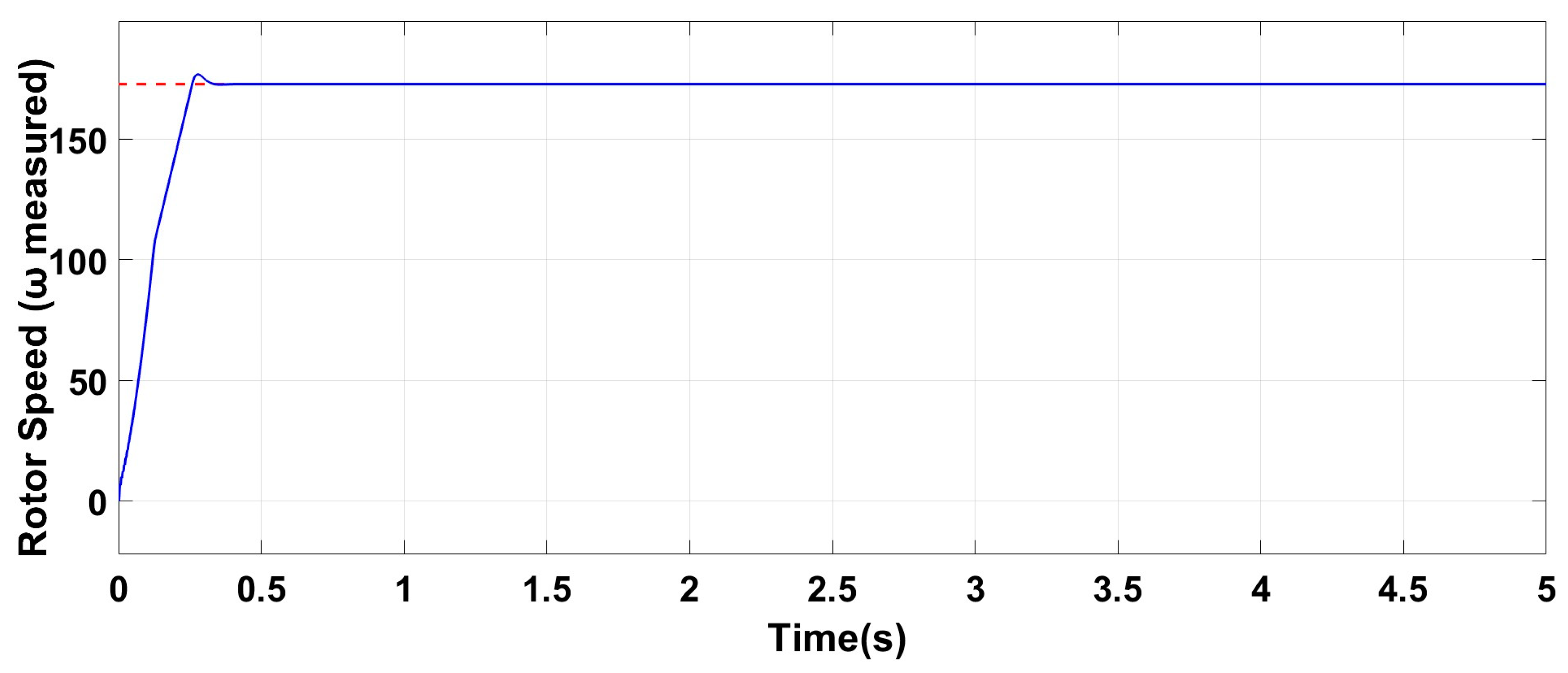
The initial transient period of 0.3 s, as shown in Figure 6, Figure 7, Figure 8 and Figure 9, is the switch-on surge of the proposed system, the maximal instantaneous rotor and stator current drawn by the DFIG when first turned on. After starting the surge period, the system takes 0.3 s to reach the steady state. This system parameter analysis indicates the proposed model’s stability and synchronism under normal running conditions.
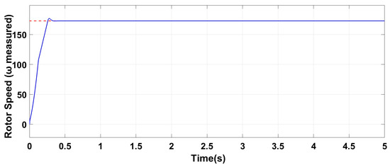
Figure 6.
Rotor speed under normal grid conditions at fixed wind speed.
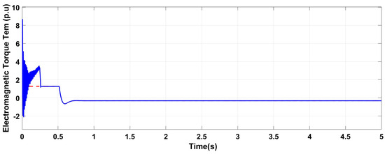
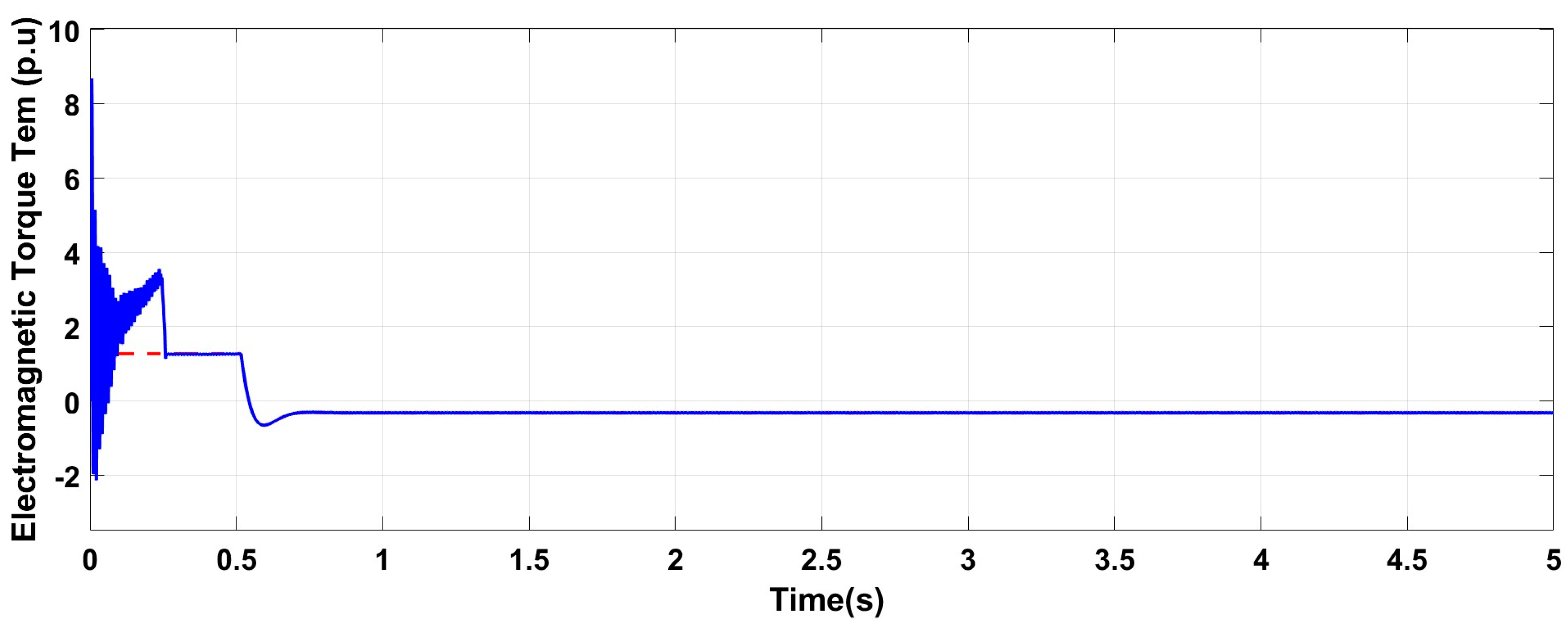
Figure 7.
Electromagnetic torque under normal grid conditions at fixed wind speed.
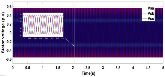
Figure 8.
Stator voltage with WSE-MPPT under normal running conditions.

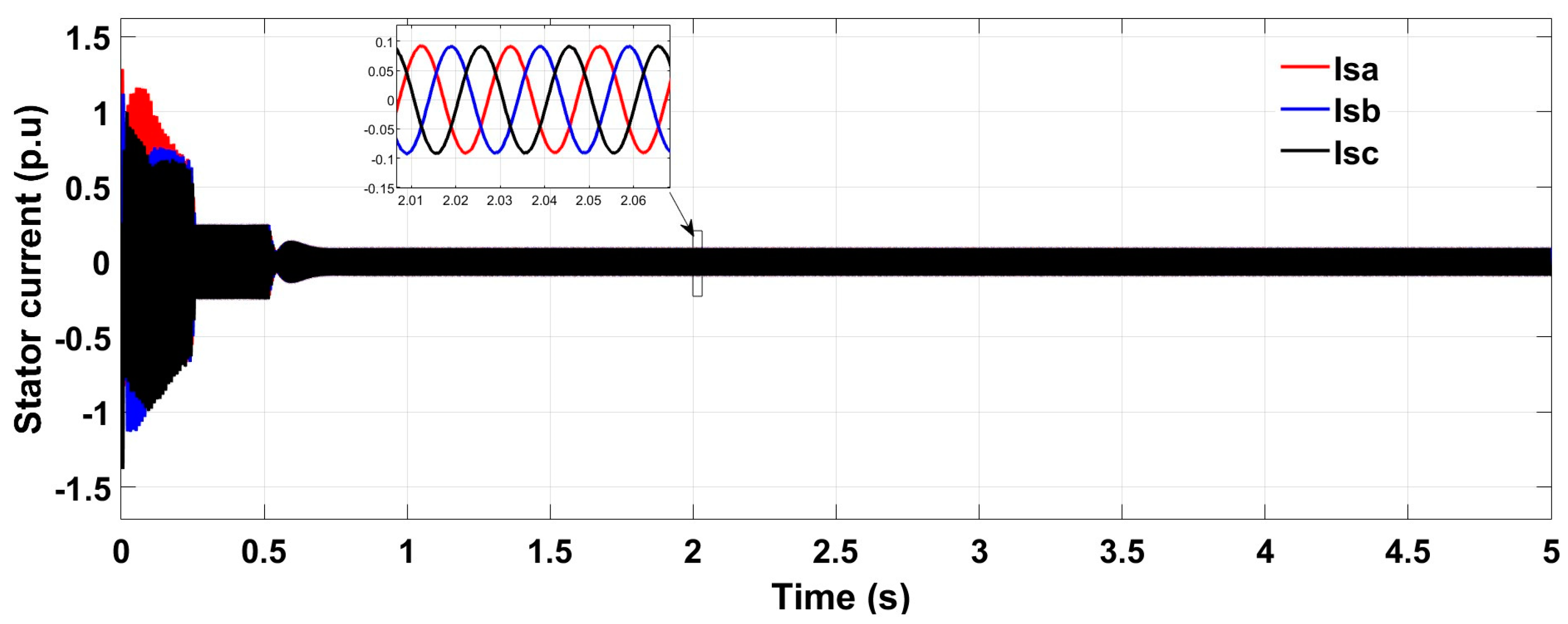
Figure 9.
Stator current with WSE-MPPT under normal running conditions.
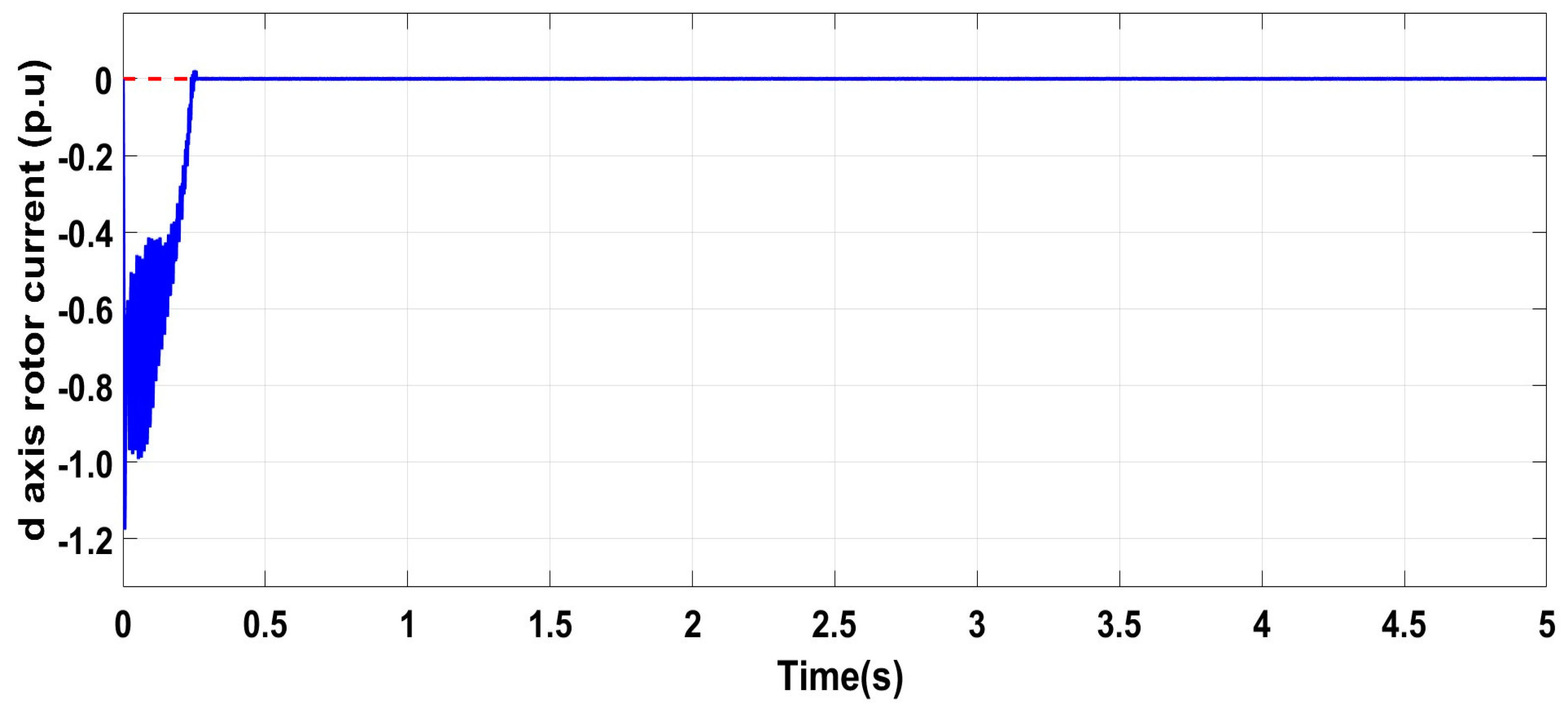
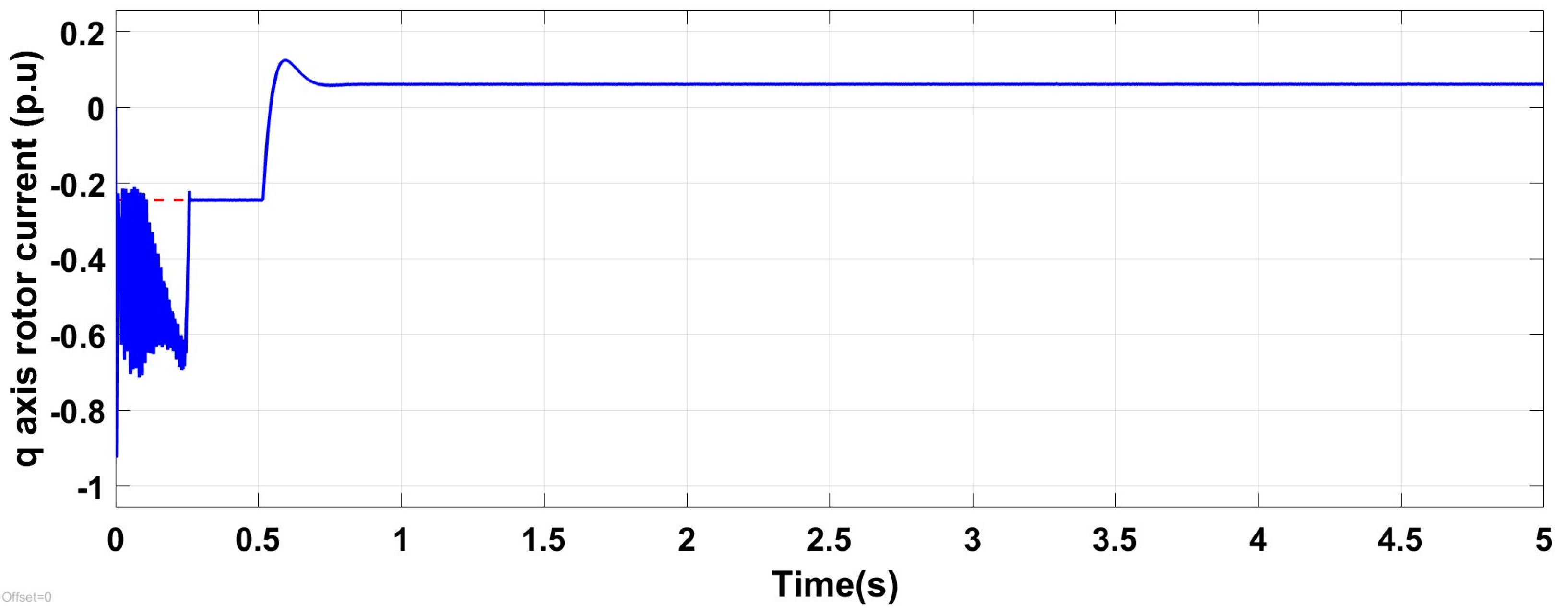
The test system operates in WSE-MPPT mode under normal running conditions at a fixed wind speed of 12 m/s, as shown in Figure 6. The rotor speed and electromagnetic torque in Figure 7 attains the steady state/normal value after starting, at time 0.3 s. It is observed that, with the wind speed estimation-based MPPT method, the system parameters, including a three-phase stator and rotor currents in Figure 10 and Figure 11, and d-q axis rotor current in Figure 12 and Figure 13, respectively, follow the rotor speed and electromagnetic torque pattern and achieve the normal running condition after accomplishing the starting period at 0.3 s, which shows the system stability.
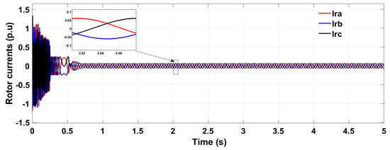
Figure 10.
Rotor current with WSE-MPPT under normal running conditions.
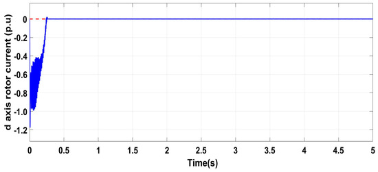
Figure 11.
d-axis rotor current with WSE-MPPT under normal running conditions.
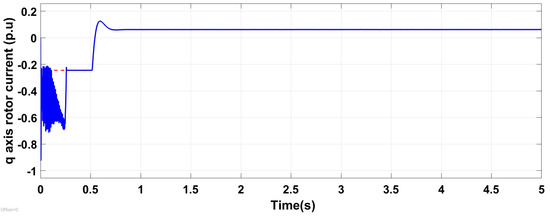
Figure 12.
q-axis rotor current with WSE-MPPT under normal running conditions.
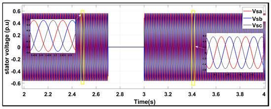
Figure 13.
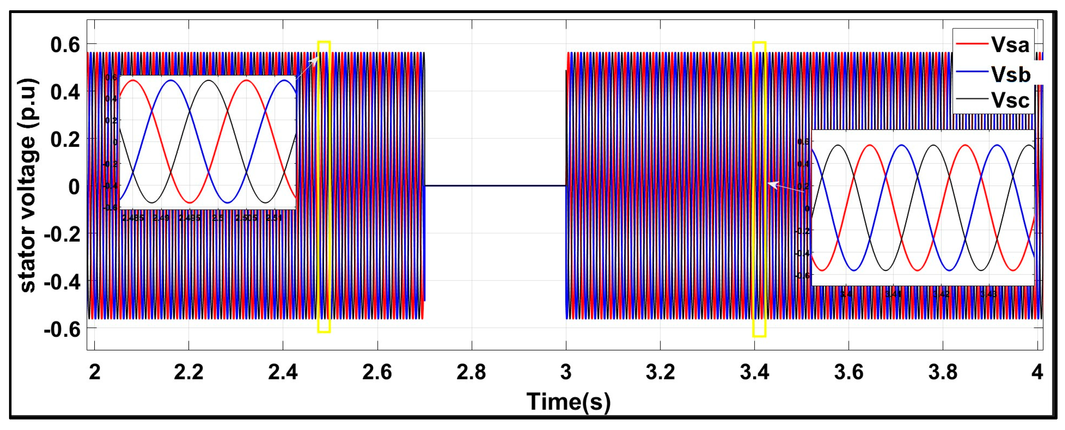
Three-phase stator voltage under a symmetrical fault with the conventional scheme.
6.2. Test Response Under a Symmetrical Three-Phase Fault with the Conventional Scheme
The most common strategy during fault occurrence is the crowbar protection scheme installed on the rotor side, which can be seen in Figure 1, to save the RSC from overcurrent. In the crowbar protection method, resistance is added on the rotor side to bypass the overcurrent during the occurrence of the fault, and, when the fault is over, the crowbar is deactivated, and normal current flows through RSC. Two drawbacks are observed in the conventional strategy during the test response under a severe symmetrical fault. The first one is that some high amplitude current appears at 2.9 s, and the second is, when the fault is over at 3.0 s, and the crowbar is deactivated, it causes an inrush current from 3.0 s–3.15 s for a period of 0.15 s.
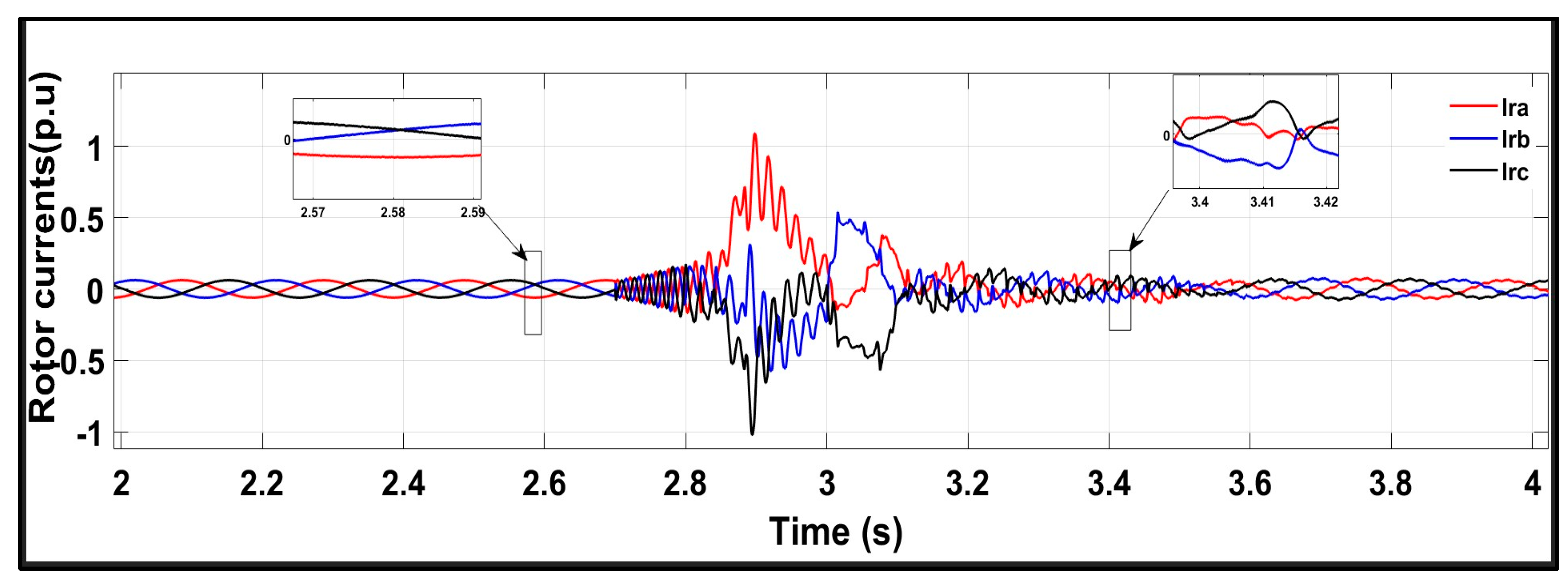
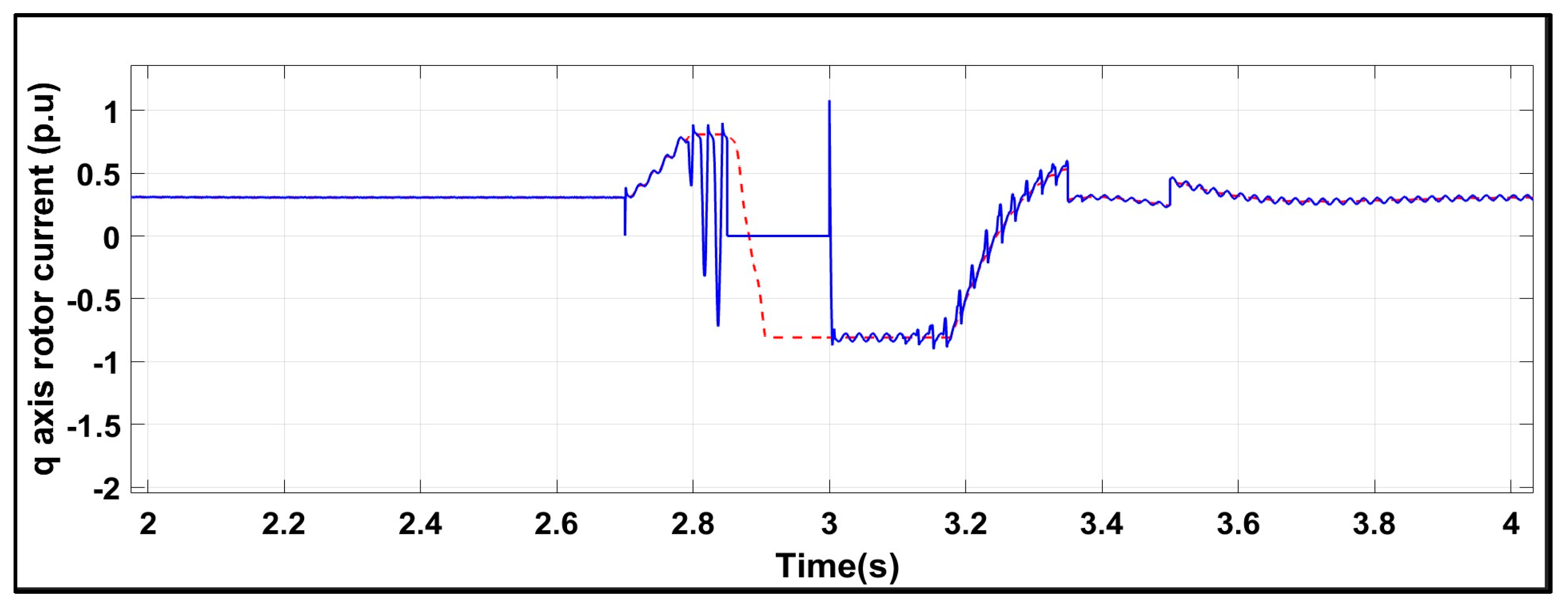
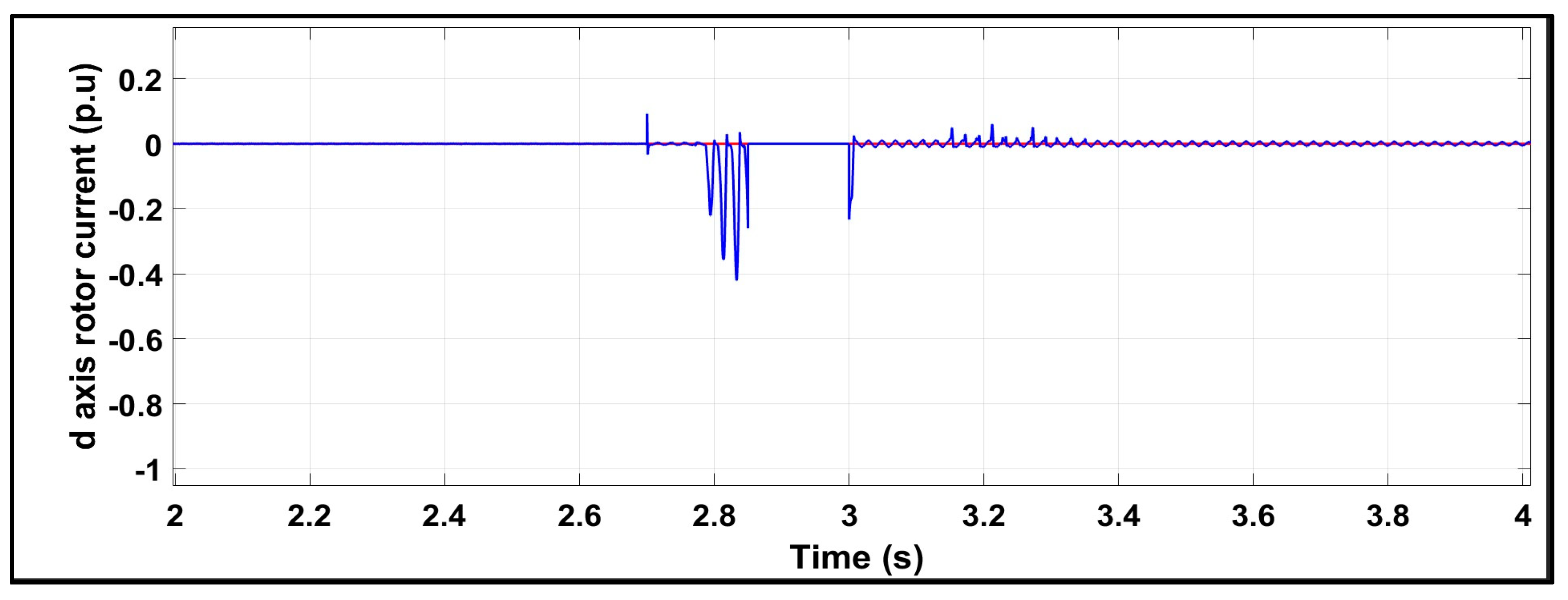
The symmetrical three-phase fault is applied to the conventional scheme for a period of 0.3 s (2.7–3.0 s). When the fault occurs at the grid, rotor and stator current surges, as shown in Figure 13 and Figure 14, reach an amplitude of more than 1 p.u, which causes a severe voltage dip of 98%, as shown in Figure 12. Meanwhile, the q-axis rotor current rises to −0.6 p.u at 2.82 s and 1 p.u at 3.0 s, and d-axis rotor current gives a peak of −0.4 p.u at 2.82 s. This high amplitude rotor transient current is above safety limits and has detrimental effects on the RSC using conventional techniques. From the three-phase stator and rotor currents, and q-axis and d-axis rotor current in Figure 14, Figure 15 and Figure 16 and Figure 17, respectively, it can be observed that, after 3.0 s, when the fault is ended and RSC is connected to the system, a large inrush current is caused with continuous transient oscillations which may also damage the RSC.
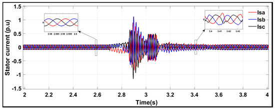
Figure 14.
Three-phase stator current under a symmetrical fault with the conventional scheme.
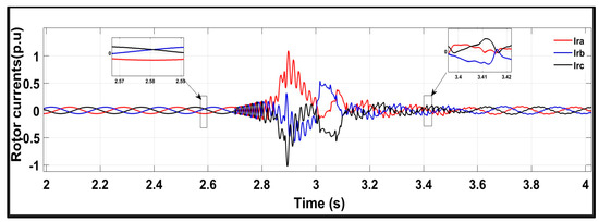
Figure 15.
Three-phase rotor current under a symmetrical fault with the conventional scheme.

Figure 16.
q axis rotor current under a symmetrical fault with the conventional scheme.

Figure 17.
d axis rotor current under a symmetrical fault with the conventional scheme.
6.3. Test Response Under a Symmetrical Three-Phase Fault with the Proposed Scheme
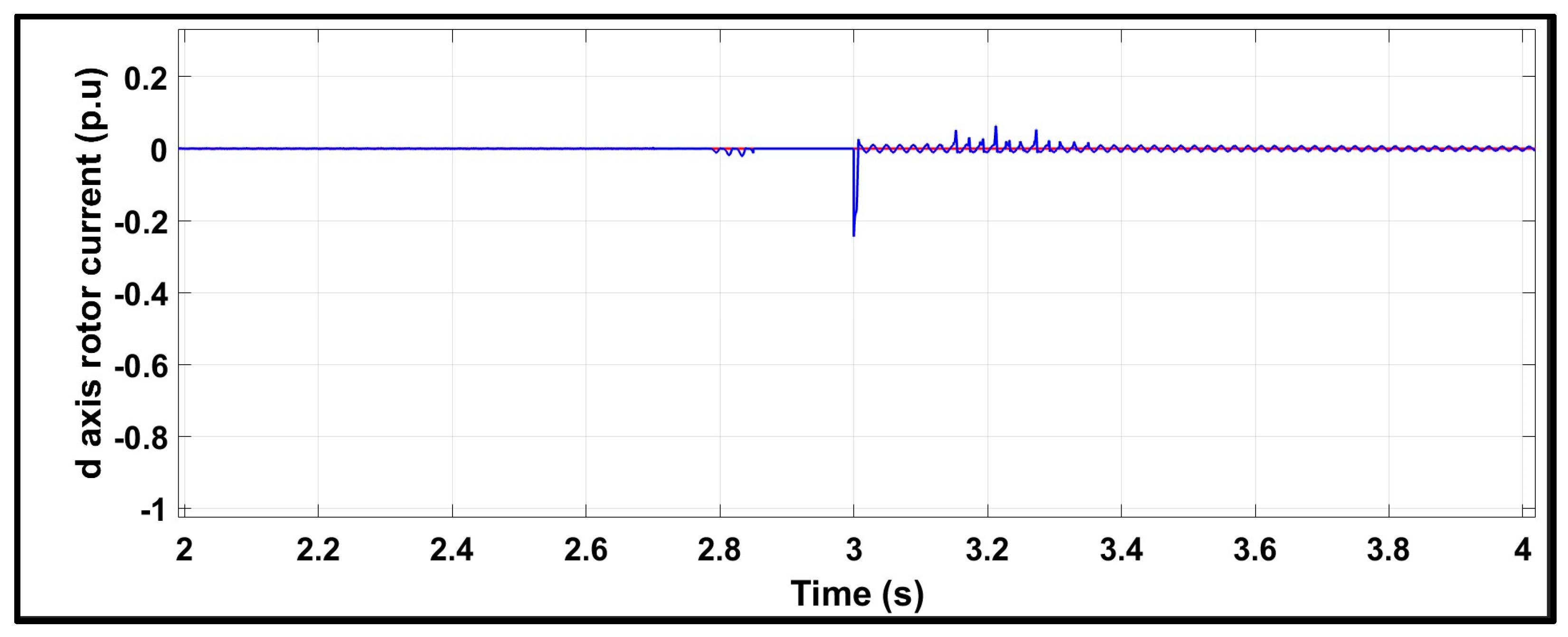
In the proposed strategy, the FRT mode is activated when the fault occurs, which turns on the crowbar scheme, as shown in Figure 3. The modified scheme reduces the two main drawbacks of high amplitude current during the fault and inrush current after the fault. On comparing the rotor and stator current during a fault in Figure 18 and Figure 19 with Figure 20 and Figure 21, it can be seen that the amplitude of the fault current is improved in the proposed scheme. When the proposed FRT-based control mode is activated during the fault, it reduces the severity of the overall fault and recovers the three-phase stator and rotor fault current amplitude to less than 1 p.u, as shown in Figure 18 and Figure 19, respectively. The improvement in d and q-axis rotor current is also can be observed in Figure 20 and Figure 21. Moreover, it can be seen from simulation results in Figure 18 and Figure 19 that, when the fault is over, and RSC is activated at 3.0, the inrush current is decreased to the normal value with improved transient oscillations. During post-fault, at T = 3.0 s, with the conventional scheme, the inrush current in Figure 14 and Figure 15 rises 0.5 p.u for a period of 0.15 s (3.0 s−3.15 s) with continuous transient oscillations from 3.15 s−3.5 s, whereas, in the proposed scheme in Figure 18 and Figure 19, the inrush rotor and stator current at T=3.0 is improved to the normal value of 0.1 p.u with improved transient oscillation. From the above analysis, the proposed scheme is very effective in handling the transient current during and after a fault, whereas the conventional crowbar scheme is ineffective in limiting the post-fault inrush current and transient oscillations.
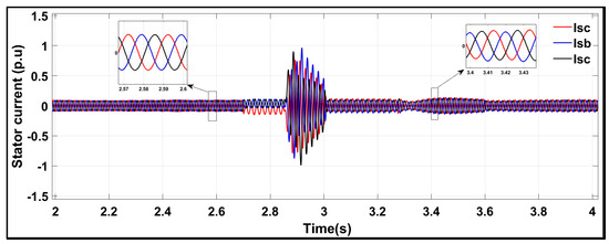
Figure 18.
Three-phase stator current under a symmetrical fault with the proposed control scheme.
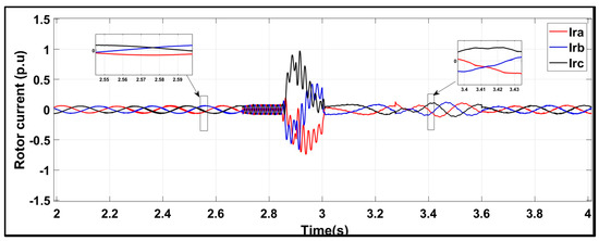
Figure 19.
Three-phase rotor current under a symmetrical fault with the proposed control scheme.
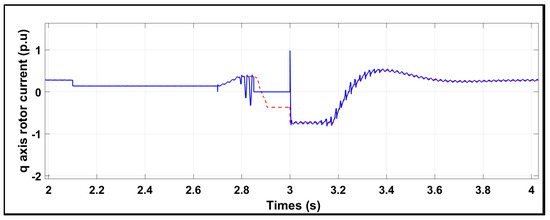
Figure 20.
q axis rotor current under a symmetrical fault with the proposed control scheme.

Figure 21.
d axis rotor current under a symmetrical fault with the proposed control scheme.
6.4. Comparing Various FRT Protection Schemes with the Proposed Approach
Table 2 and Table 3 compare the rotor current transient of different FRT-based approaches with the proposed scheme, namely, DC chopper, crowbar circuit based on series dynamic braking resistor, fault-tolerant wind energy conversion system, and model predictive voltage control. The comparison shows improved transient rotor current (p.u) of the proposed approach during a fault and after the fault.
Table 2.
Comparison in terms of overshoot of rotor current during a fault.
Table 3.
Comparison in terms of inrush current after a fault.
7. Conclusions
This paper proposes a systematized and synchronized dual-mode operating technique that effectively controls the system parameters during normal running and severe fault conditions. The proposed control technique combines the operations of the WSE-MPPT mode during normal running conditions and the enhanced crowbar-based FRT mode under a severe symmetrical three-phase fault, and the behavior of the proposed technique is analyzed and compared with the conventional technique. The amplitude of rotor fault current under a severe voltage dip of 98% is reduced to 1.0 p.u with less fault severity using the proposed technique, whereas the conventional technique shows higher fault amplitude with more severity of fault current. When the fault is over at 3.0 s, the proposed active impedance-based FRT technique reduces inrush current and transient oscillation, which can be seen in the rotor and stator currents compared to conventional techniques. The d-axis and q-axis rotor currents also show a low amplitude of fault current and less distortion after a fault in the proposed control scheme.
Author Contributions
Conceptualization, R.A.T., G.S.K. and E.T.; Methodology, A.A., M.A.B., G.A. and P.M.; Software, G.S.K., M.A.B. and M.H.; Validation, R.A.T.; Formal analysis, M.H. and P.M.; Investigation, A.A. and M.A.B.; Data curation, R.A.T.; Writing—original draft, R.A.T., A.A., G.A., M.H., P.M. and E.T.; Writing—review & editing, Ghulam Abbas; Supervision, G.S.K.; Funding acquisition, E.T. All authors have read and agreed to the published version of the manuscript.
Funding
This research was funded by Department of Electrical Engineering Quaid-e-Awam University of Engineering Science and Technology, Nawabshah, Pakistan.
Data Availability Statement
The data presented in this study are available on request from the corresponding author.
Acknowledgments
The authors extend their appreciation to the Deanship of Scientific Research at Northern Border University, Arar, KSA for funding this research work through the project number “NBU-FFR-2025-2448-01”.
Conflicts of Interest
The authors declare no conflicts of interest.
References
- Gidwani, L. A comparative power quality study of DFIG and PMSG based wind Energ Conversion System. WSEAS Trans. Syst. Control. 2015, 10, 38–47. [Google Scholar]
- Beainy, A.; Maatouk, C.; Moubayed, N.; Kaddah, F. Comparison of different type of generator for wind energy conversion system topologies. In Proceedings of the 2016 3rd international conference on renewable energies for developing countries (REDEC-IEEE), Zouk Mosbeh, Lebanon, 13–15 July 2016; pp. 1–6. [Google Scholar]
- Dahiya, V.; Leena, G. Comparative study of DFIG and PMSG in wind energy conversion system. Int. J. Electr. Eng. Technol. (IJEET) 2019, 10, 73–79. [Google Scholar]
- Howlader, A.M.; Senjyu, T. A Comprehensive review of low voltage ride through capabiligy strategies for wind energy conversion system. Renew. Energy Sustain. Energy Rev. 2016, 56, 643–658. [Google Scholar] [CrossRef]
- Youssef, A.R.; Sayed, M.A.; Abdel-Wahab, M. MPPT control technique for direct drive five-phase PMSG wind turbines with wind speed estimation. Int. J. Sustain. Green Energy 2015, 4, 195–205. [Google Scholar]
- Mousa, H.H.; Youssef, A.R.; Mohamed, E.E. Variable step size P and O MPPT algorithm for optimal power extraction of multi-phase PMSG based wind generation system. Int. J. Electr. Power Energy Syst. 2019, 108, 218–231. [Google Scholar] [CrossRef]
- Jiao, X.; Sun, Y.; Ying, Y.; Yang, Q. Effective wind speed extimation based maximum power point tracking control for variable-speed wind turbine. In Proceedings of the Chinese Automation Congress, Jinan, China, 20–22 October 2017; pp. 6685–6690. [Google Scholar]
- Hossain, M.E. Performance of new solid-state fault current limiter for transient stability enhancement of DFIG based wind generator. In Proceedings of the North American Power Symposium Conference (NAPS), Morgantown, WV, USA, 17–19 September 2017. [Google Scholar]
- Lingling, F.; Zhixin, M. Modeling and Analysis of Doubly Fed Induction Generator Wind Energy Systems; Elsevier: Amsterdam, The Netherlands, 2015. [Google Scholar]
- Kaloi, G.S.; Wang, J.; Baloch, M.H. Active and reactive power control of the doubly fed induction generator based on wind energy conversion system. Energy Rep. 2016, 2, 194200. [Google Scholar] [CrossRef]
- Ibrahim, A.O.; Nguyen, T.H.; Lee, D.-C.; Kim, S.-C. A fault ride- through technique of DFIG wind turbine systems using dynamic voltage restorers. IEEE Trans. Energy Convers. 2011, 26, 871–882. [Google Scholar] [CrossRef]
- Shen, Y.-W.; Ke, D.-P.; Sun, Y.-Z.; Kirschen, D.S.; Qiao, W.; Deng, X.-T. Advanced auxiliary control of an energy storage device for transient voltage support of a doubly fed induction generator. IEEE Trans. Sustain. Energy 2016, 7, 63–76. [Google Scholar] [CrossRef]
- de Souza, V.R.F.B.; Barros, L.S.; Costa, F.B. Modular multilevel converter for low-voltage ride-through support in AC networks. Energies 2021, 14, 5314. [Google Scholar] [CrossRef]
- Vinothkumar, K.; Selvan, M.P. Novel scheme for enhancement of fault ride- through capability of doubly fed induction generator based wind farms. Energy Convers Manag. 2011, 52, 2651–2658. [Google Scholar] [CrossRef]
- Rahimi, M.; Parniani, M. Grid-fault ride-through analysis and control of wind turbines with doubly fed induction generators. Electr. Power Syst. Res. 2010, 80, 184–196. [Google Scholar] [CrossRef]
- Dai, J.; Xu, D.; Wu, B.; Zargari, N.R. Unified DC-link current control for low-voltage ride-through in current-source-converter-based wind energy conversion systems. IEEE Trans Power Electron 2011, 26, 288–297. [Google Scholar]
- Yang, L.; Xu, Z.; Østergaard, J.; Dong, Z.Y.; Wong, K.P. Advanced Control Strategy of DFIG Wind Turbines for Power System Fault Ride Through. IEEE Trans. Power Syst. 2011, 27, 713–722. [Google Scholar] [CrossRef]
- Sami, I.; Ullah, S.; Amin, S.U.; Al-Durra, A.; Ullah, N.; Ro, J.-S. Convergence enhancement of super twisting sliding mode control using artificial neural network for DFIG based wind energy conversion systems. IEEE Access 2022, 10, 97625–97641. [Google Scholar] [CrossRef]
- Haro-larrode, M.; Santos-Mugica, M.; Eguia, P.; Rodriguez-Sanchez, R.; Gil-de-Muro, A. Impact of propostional resonant controller parameters of VSC connected to AC grids with variable X/R characterics on the small signal stability. Int. J. Electr. Power Energy Syst. 2020, 118, 105746. [Google Scholar] [CrossRef]
- Rohten, J.A.; Silva, J.J.; Munoz, J.A.; Villarroel, F.A.; Dewar, D.N.; Rivera, M.E.; Espinoza, J.R. A simple self tunning resonan control approach for power electronics connected micro grids with distorted voltage conditions. IEEE Access 2020, 8, 216018–216028. [Google Scholar] [CrossRef]
- Damas, R.N.; Son, Y.; Yoon, M.; Kim, S.-Y.; Choi, S. Subsynchronous oscillation and advanced analysis: A review. IEEE Access 2020, 8, 224020–224032. [Google Scholar] [CrossRef]
- Yao, J.; Pei, J.; Xu, D.; Liu, R.; Wang, X.; Wang, C.; Li, Y. Coordinated control of a hybrid wind farm with DFIG-based and PMSG-based wind power generation systems under asymmetrical grid faults. Renew. Energy 2018, 127, 613–629. [Google Scholar] [CrossRef]
- Jin, J.; Yang, R.; Zhang, R.; Fan, Y.; Xie, Q.; Chen, X. Combined low voltage ride through and power smoothing control for DFIG/PMSG hybrid wind energy conversion system employing a SMES-based AC-DC unified power quality conditioner. Int. J. Electr. Power Energy Syst. 2021, 128, 106733. [Google Scholar] [CrossRef]
- Yesudhas, A.; Palanimuthu, K.; Lee, S.; Jeong, J.; Joo, Y. Performance enhancement of PMSG-based WECS using robust adaptive fuzzy sliding mode control. Control. Eng. Pract. J. 2025, 156, 106211. [Google Scholar] [CrossRef]
- Yang, L.; He, X.; Zhang, P.; Liu, S. Control scheme and performance analysis of dual-frequency single-phase grid-connected inverter interfaced with weak and distorted grids. IEEE Access 2020, 8, 178639–178650. [Google Scholar] [CrossRef]
- de Bosio, F.; Pastorelli, M.; Ribeiro, L.A.D.S.; Lima, M.S.; Freijedo, F.; Guerrero, J.M. Current control loop design and analysis based on resonant regulators for microgrid applications. In Proceedings of the IECON 2015-41st Annual Conference of the IEEE Industrial Electronics Society, Yokohama, Japan, 9–12 November 2015; pp. 5322–5327. [Google Scholar] [CrossRef]
- Haro-Larrode, M.; Bergna-Diaz, G.; Eguia, P.; Santos-Mugica, M. On the Tuning of Fractional Order Resonant Controllers for a Voltage Source Converter in a Weak AC Grid Context. IEEE Access 2021, 9, 52741–52758. [Google Scholar] [CrossRef]
- Chehaidia, S.E.; Abderezzak, A.; Kherfane, H.; Guersi, N.; Cherif, H.; Boukhezzar, B. Fuzzy gain scheduling of PI torque controller to capture the maximum power from variable speed wind turbines. In Proceedings of the 2020 IEEE 2nd International Conference on Electronics, Control, Optimization and Computer Science (ICECOCS), Kenitra, Morocco, 2–3 December 2020; pp. 1–6. [Google Scholar]
- Nouriani, A.; Moradi, H. Variable speed wind turbine power control: A comparison between multiple LVRT based methods. Int. J. Dyn. Control. 2022, 10, 654–667. [Google Scholar] [CrossRef]
- Kazemi Golkhandan, R.; Aghaebrahimi, M.R.; Farshad, M. Control strategies for enhancing frequency stability by DFIGs in a power system with high percentage of wind power penetration. Appl. Sci. 2017, 7, 1140. [Google Scholar] [CrossRef]
- Shahbazi, M.; Poure, P.; Saadate, S. Real-time power switch fault diagnosis and fault-tolerant operation in a DFIG-based wind energy system. Renew. Energy 2018, 116, 209–218. [Google Scholar] [CrossRef]
- Chojaa, H.; Derouich, A.; Taoussi, M.; Chehaidia, S.E.; Zamzoum, O.; Mosaad, M.I.; Alhejji, A.; Yessef, M. Nonlinear Control Strategies for Enhancing the Performance of DFIG-Based WECS under a Real Wind Profile. Energies 2022, 15, 6650. [Google Scholar] [CrossRef]
- Almozayen, M.A.; Knight, A.M. Modeling Grid-Connected DFIG under System Disturbances using Dynamic Phasor FEM. In Proceedings of the 2022 International Conference on Electrical Machines (ICEM), Valencia, Spain, 5 September 2022; pp. 380–386. [Google Scholar] [CrossRef]
- Kang, Z.; Li, J. Zero-Voltage Ride-Through Scheme of PMSG Wind Power System Based on NLESO and GFTSMC. Electronics 2023, 12, 4348. [Google Scholar] [CrossRef]
- Bekiroglu, E.; Yazar, M.D. Fault-Ride through Improvement of DFIG under Symmetrical/Asymmetrical Voltage Dips. Electr. Power Compon. Syst. 2023, 51, 510–523. [Google Scholar] [CrossRef]
- Kaloi, G.S.; Baloch, M.H.; Kumar, M.; Soomro, D.M.; Chauhdary, S.T.; Memon, A.A.; Ishak, D. An LVRT Scheme for Grid Connected DFIG Based WECS Using State Feedback Linearization Control Technique. Electronics 2019, 8, 777. [Google Scholar] [CrossRef]
- Naderi, S.B.; Negnevitsky, M.; Muttaqi, K.M. A Modified DC Chopper for Limiting the Fault Current and Controlling the DC-Link Voltage to Enhance Fault Ride-Through Capability of Doubly-Fed Induction-Generator-Based Wind Turbine. IEEE Trans. Ind. Appl. 2019, 55, 2021–2032. [Google Scholar] [CrossRef]
- Ekanayake, J.B.; Holdsworth, L.; Jenkins, N. Comparison of 5th order and 3rd order machine models for double fed induction generators (DFIG) wind turbines. Electr. Power Syst. Res. 2003, 67, 207–215. [Google Scholar] [CrossRef]
- Krause, P.C. Analysis of Electric Machinery, 2nd ed.; McGraw-Hill: New York, NY, USA, 2002. [Google Scholar]
- Döşoğlu, M.K. Crowbar hardware design enhancement for fault ride through capability in doubly fed induction generator-based wind turbines. ISA Trans. 2020, 104, 321–328. [Google Scholar] [CrossRef]
- Lei, Y.; Mullane, A.; Lightbody, G.; Yacamini, R. Modeling of the wind turbine with a doubly fed induction generator for grid integration studies. IEEE Trans Energy Convers 2006, 21, 257–264. [Google Scholar] [CrossRef]
- Rahimi, M.; Azizi, A. Transient behavior representation, contribution to fault current assessment, and transient response improvement in DFIG-based wind turbines assisted with crowbar hardware. Int. Trans. Electr. Energy Syst. 2018, 29, e2698. [Google Scholar] [CrossRef]
- Raghavendran, C.R.; Roselyn, J.P.; Devaraj, D. Development and performance analysis of intelligent fault ride through control scheme in the dynamic behavior of grid connected DFIG based wind systems. Energy Rep. 2020, 6, 2560–2576. [Google Scholar] [CrossRef]
- Pannell, G.; Zahawi, B.; Atkinson, D.J.; Missailidis, P. Evaluation of the Performance of a DC-Link Brake Chopper as a DFIG Low-Voltage Fault-Ride-Through Device. IEEE Trans. Energy Convers. 2013, 28, 535–542. [Google Scholar] [CrossRef]
- Okedu, K.E.; Muyeen, S.M.; Takahashi, R.; Tamura, J. Wind Farms Fault Ride Through Using DFIG With New Protection Scheme. IEEE Trans. Sustain. Energy 2012, 3, 242–254. [Google Scholar] [CrossRef]
- Jabbour, N.; Tsioumas, E.; Medemlis, C.; Solomin, E. A highly effective Fault-Ride-Through Strategy for a wind Energy Conversion System with DFIG. IEEE Trans. Power Electron. 2020, 35, 8154–8164. [Google Scholar] [CrossRef]
- Mossa, M.A.; Do, T.D.; Al-Sumaiti, A.S.; Quynh, N.V.; Diab, A.A.Z. Effective Model Predictive Voltage Control for a Sensorless Doubly Fed Induction Generator. IEEE Can. J. Electr. Comput. Eng. 2021, 44, 50–64. [Google Scholar] [CrossRef]
- Zou, X.; Zhu, D.; Hu, J.; Zhou, S.; Kang, Y. Mechanism Analysis of the Required Rotor Current and Voltage for DFIG-Based WTs to Ride-Through Severe Symmetrical Grid Faults. IEEE Trans. Power Electron. 2018, 33, 7300–7304. [Google Scholar] [CrossRef]
- Ali, M.A.S.; Mehmood, K.K.; Baloch, S.; Kim, C.-H. Modified rotor-side converter control design for improving the LVRT capability of a DFIG-based WECS. Electr. Power Syst. Res. 2020, 186, 106403. [Google Scholar] [CrossRef]
- Ansari, A.A.; Dyanamina, G. Fault Ride-Through Operation Analysis of Doubly Fed Induction Generator-Based Wind Energy Conversion Systems: A Comparative Review. Energies 2022, 15, 8026. [Google Scholar] [CrossRef]


Disclaimer/Publisher’s Note: The statements, opinions and data contained in all publications are solely those of the individual author(s) and contributor(s) and not of MDPI and/or the editor(s). MDPI and/or the editor(s) disclaim responsibility for any injury to people or property resulting from any ideas, methods, instructions or products referred to in the content. |
© 2025 by the authors. Licensee MDPI, Basel, Switzerland. This article is an open access article distributed under the terms and conditions of the Creative Commons Attribution (CC BY) license (https://creativecommons.org/licenses/by/4.0/).