1. Introduction
Pure electric vehicles can be classified as possessing either centralized drive or distributed drive systems according to the layout of their drive motor. Centralized drive technology is mature and safe, but the drive system itself does not have dynamic control performance [
1]. The torque of each wheel of a distributed drive system is independently controllable, which can realize various dynamic control functions such as anti-skid driving and differential steering [
2,
3,
4]. However, when the drive motor fails [
5,
6], complex dynamic control is required to maintain safe driving of the vehicle, which increases the complexity of the control system. By combining the advantages of the above centralized drive and distributed drive systems and avoiding their disadvantages, our research group has invented a dual-mode coupling drive system as shown in
Figure 1, which can use both centralized drive and distributed drive and has a two-speed transmission capacity [
7]. The system can also use a single-motor centralized drive mode in the case of unilateral drive motor failure, and improve the safety of the distributed drive. The drive system achieves different driving modes by controlling the position of the joint sleeve in the synchronizer through the shift actuator [
8,
9]. An existing single actuator is shown in
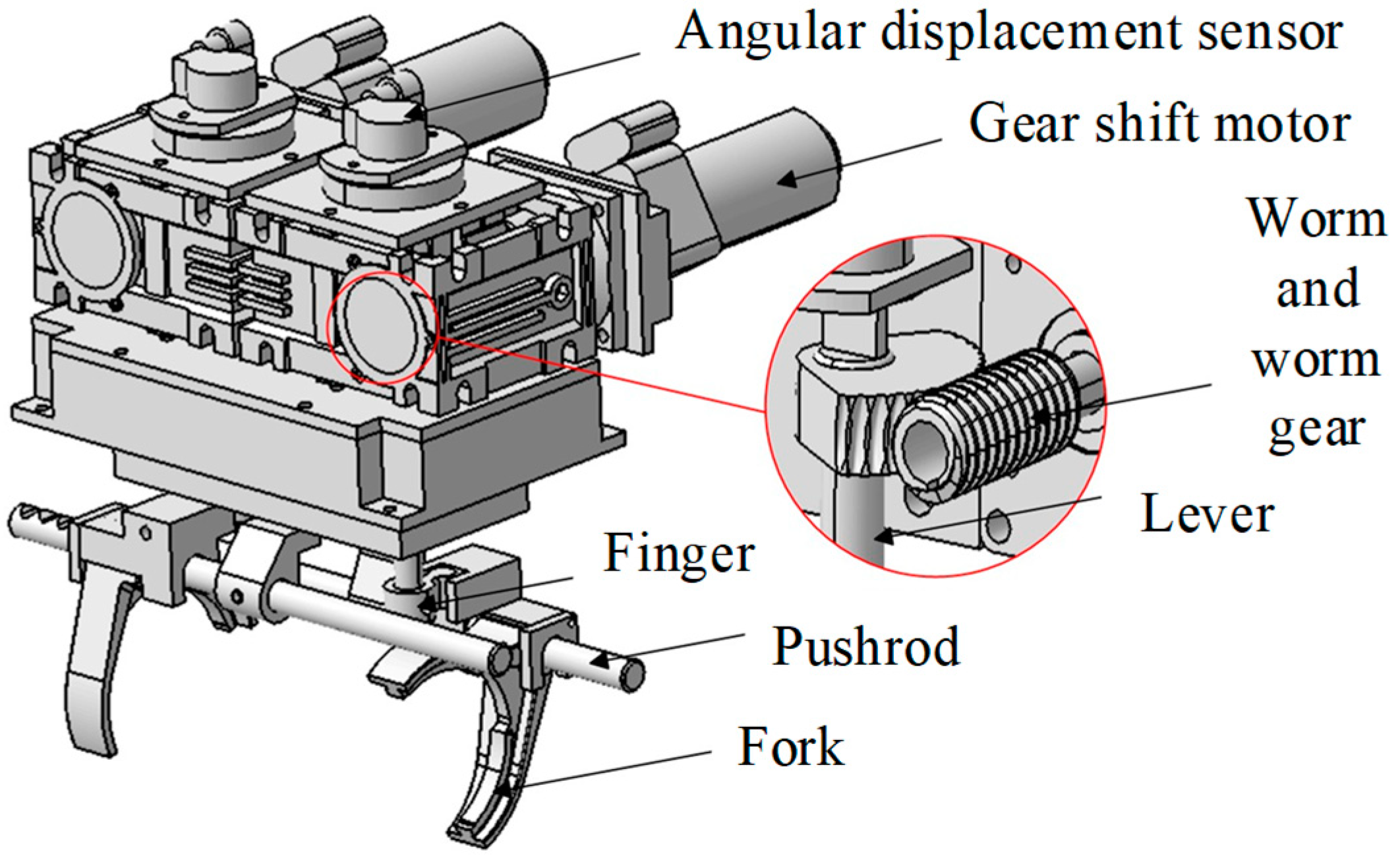
Figure 2. It includes a selector motor and a shift motor, which are decelerated by a worm gear. The selector motor controls the up and down movement of the lever to achieve simultaneous or independent fork control. The shift motor controls the rotation of the lever and plays a role in mode switching. In order to ensure the safety of shifting, the left and right shift forks are moved by a single lever. If one side fails to engage, the other side cannot engage. However, due to the mechanical coupling between the left and right sides, there is a mutual interference problem between the synchronizers on both sides, that is, at any stage of the shift process, one side must wait for the other side to complete the corresponding stage before entering the next stage. This will extend the power interruption time. Moreover, there are gaps in the real system, and it is impossible to ensure that the synchronizers on both sides are in the same stage when shifting, thus causing shifting shock. Therefore, in view of this mutual interference problem existing in single actuators, a new design and control method of shift actuators is required.
Domestic and foreign scholars have performed a lot of research on the structural design of shift actuators. Hu et al. added grooves to the camshaft [
10]. The rotation of the camshaft drives the shift fork to move to achieve gear shifting. However, wear will occur at the contact between the shift fork and the camshaft, which will lead to a decrease in gear shifting accuracy after long-term use. Lin et al. used electromagnetic linear actuators to achieve precise shift displacement control, but the actuator itself was large and occupied cabin space [
11]. Petrov et al. designed a self-holding three-position electric tubular actuator that could achieve a shifting function and had a holding force of 50 N [
12]. Its disadvantages are that it had a complex structure and occupied a large space. Szabó Á et al. designed a floating piston pneumatic actuator, which consisted of a double-acting floating cylinder, a shift finger and other components [
13]. It had a large shift force, but the pneumatic device was large in size, which affected the layout of the transmission. The above-mentioned shifting actuator can achieve a shifting function. However, considering the compact structure and manufacturing cost of a dual-mode coupling drive system, the above-mentioned shifting actuator is not suitable for use in dual-mode coupling drive electric vehicles.
The mode-switching principle of a dual-mode coupling drive system is similar to the AMT (automated manual transmission) shifting principle, and the related research content can be used as a reference for this study. Zhong et al. used the LQR algorithm to control the shift actuator and improved shift quality [
14], but the shift time still needed to be further optimized. Gao et al. used the fast motor response method to reduce the shift time for their invented I-AMT [
15], but the sliding friction was considerable, and the problem of overheating causing damage to the friction surface still needs to be considered. Wang et al. designed a double-loop self-learning fuzzy control framework [
16]. The outer loop adjusts the expected trajectory of the actuator motor through fuzzy logic, and the inner loop controls the trajectory of the actuator motor through the model reference self-learning method. This method can control AMT without accurate system parameters. Montazeri-Gh et al. designed an AMT control strategy for parallel hybrid vehicles [
17]. According to the local traffic conditions, the genetic algorithm was used to optimize the shift control, which improved the economy of the vehicle, but did not consider the shift quality problem. Roozegar et al. used a discrete PID controller for shift control, and used a trial-and-error method and genetic algorithm to optimize PID, which achieved the initial requirements of fast shifting, and still needed to be optimized in the later stage to achieve better results [
18].
In order to solve the problem of mutual interference during the mode switching of single actuators and improve the compactness of shift actuators, a new dual actuator is designed based on the original shift actuator. The mode switching process is theoretically analyzed, and a staged control method is designed to improve the quality of mode switching. In this paper, a dual actuator is designed and the dynamic model of a shift actuator is established. Secondly, a theoretical analysis of the dual-mode coupling drive system’s shift process is carried out. Next, the mutual interference mechanism of the single actuator is analyzed. Then, the dual-actuator shift control method is studied. Finally, the effectiveness of the dual-actuator shift control is verified by real vehicle tests.
3. Analysis of Mutual Interference Mechanism of Single Actuator
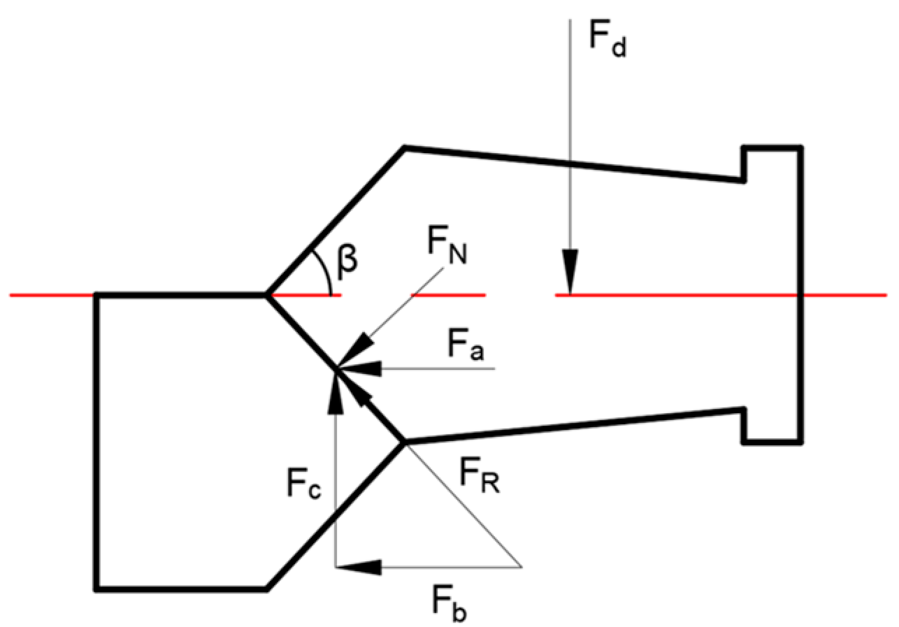
The motion plane diagram of single-actuator gear shifting is shown in
Figure 5. When the single-actuator gear shift is used, the left and right sleeves are controlled by one finger, which may cause the following problems. There must be gaps between parts due to wear or assembly, so the stage on both sides may be different when shifting. The synchronous torques during the synchronization process are inconsistent, and the completion time is different. The side with a smaller speed difference can enter the next stage in advance under the drive of the shift motor while the side with a larger speed difference has not yet completed synchronization. Due to the mechanical coupling relationship on both sides, this will prevent the side with a smaller speed difference from entering the next stage. It may also cause shocks due to forced gear shifting. The target gear speeds will be inconsistent when the wheels on both sides are turning or sliding, and the speed regulation performance of the drive motors on both sides cannot be guaranteed to be exactly the same, which leads to the side that has completed speed regulation having to wait for the other side to complete speed regulation before it can shift gears. During the important stage of tooth shifting, if there is a collision on one side, this will directly affect the tooth shifting state on the other side. Due to the above reasons, there is mutual interference between the two sides of the single actuator, which will cause the power interruption time to be prolonged and the shift shock to seriously affect shift quality.
The interference caused by the shift speed regulation stage is mainly reflected in the extension of the power interruption time. The existence of a gap mainly affects the gear shift shock, and due to the difficulty in installing the sensor, it cannot be verified through using a real vehicle. Therefore, this paper uses Adams (2019) to establish a shift actuator model to simulate and analyze the mutual interference problem of single actuators. The simulation results are shown in
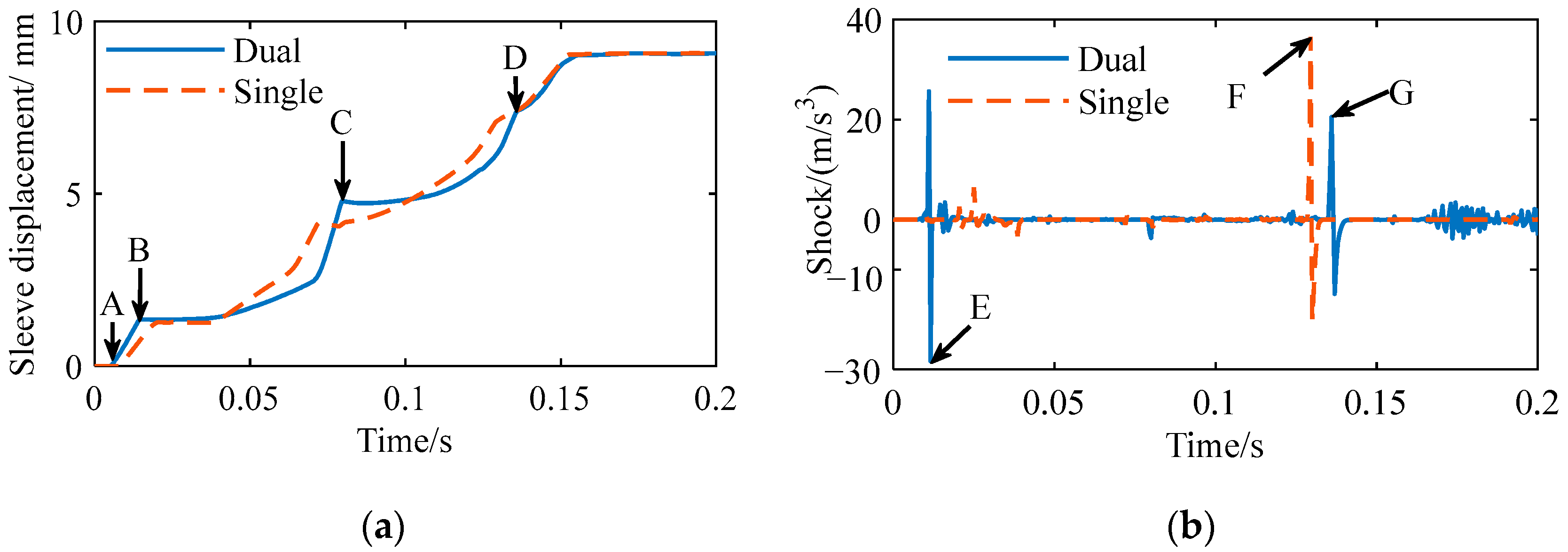
Figure 6; the displacement of the left and right sleeves of the single actuator at point A is inconsistent. The stage indicated by arrows A and B, i.e., 0.04–0.065 s, is the ring-shifting stage. In this stage, the displacement curves of the left and right coupling sleeves of the single actuator are different, i.e., the synchronization time required for the above two sides is different. One side completes synchronization first, but the other side does not, so the coupling sleeve on the completed side tends to enter the ring-shifting stage in advance. The axial resistance of the synchronizer that enters the ring-shifting stage in advance will disappear, and when the other side enters the ring-shifting stage, mutual interference will occur, resulting in obvious shock in the later stages. The shock on the left side is greater because the right side enters the ring-shifting stage early, causing interference on the left side. The time of shock on the left and right sides is not consistent, but relatively close. The shock is random. The simulation shows that the single-actuator shift will produce mutual interference and lead to a higher shock when the gap between the left and right sides is inconsistent.
4. Design of Fuzzy PID Controller Stage
According to the analysis of the shifting process in
Section 2.1, the forces in each stage are not the same, so using different controllers for different stages can achieve better control effects. Fuzzy PID is based on PID, according to the relationship between the error change rate and the error correction PID control parameters in real time; the modified parameters are input into the PID controller through continuous feedback regulation so that the controlled object has good dynamic performance [
24]. The structure of the fuzzy PID control system is shown in
Figure 7.
According to the error
e and the error change rate
ec, the control system uses the fuzzy controller to obtain the correction of the three parameters
Kp,
Ki and
Kd. The adjustment mechanism can be expressed as follows:
where
Kp−1 is the proportional constant of the previous period, Δ
Kp is the proportional constant correction,
Ki−1 is the integral constant of the previous period, Δ
Ki is the correction of integral constant,
Kd−1 is the differential constant of the previous period and Δ
Kd is the correction of differential constant.
4.1. Design and Implementation of Fuzzy Controller
The fuzzy controller must first fuzzify the input and output quantities and formulate fuzzy rules, then defuzzify the output and finally obtain the output quantity. The fuzzy control process is shown in
Figure 8, including fuzzification, fuzzy reasoning and defuzzification.
- (1)
Input and output fuzzification
Firstly, the input quantity was fuzzified, and the fuzzy domains of the error
e and error change rate
ec were defined as [−2,2] and [−8,8], respectively. The fuzzy domains of Δ
Kp, Δ
Ki and Δ
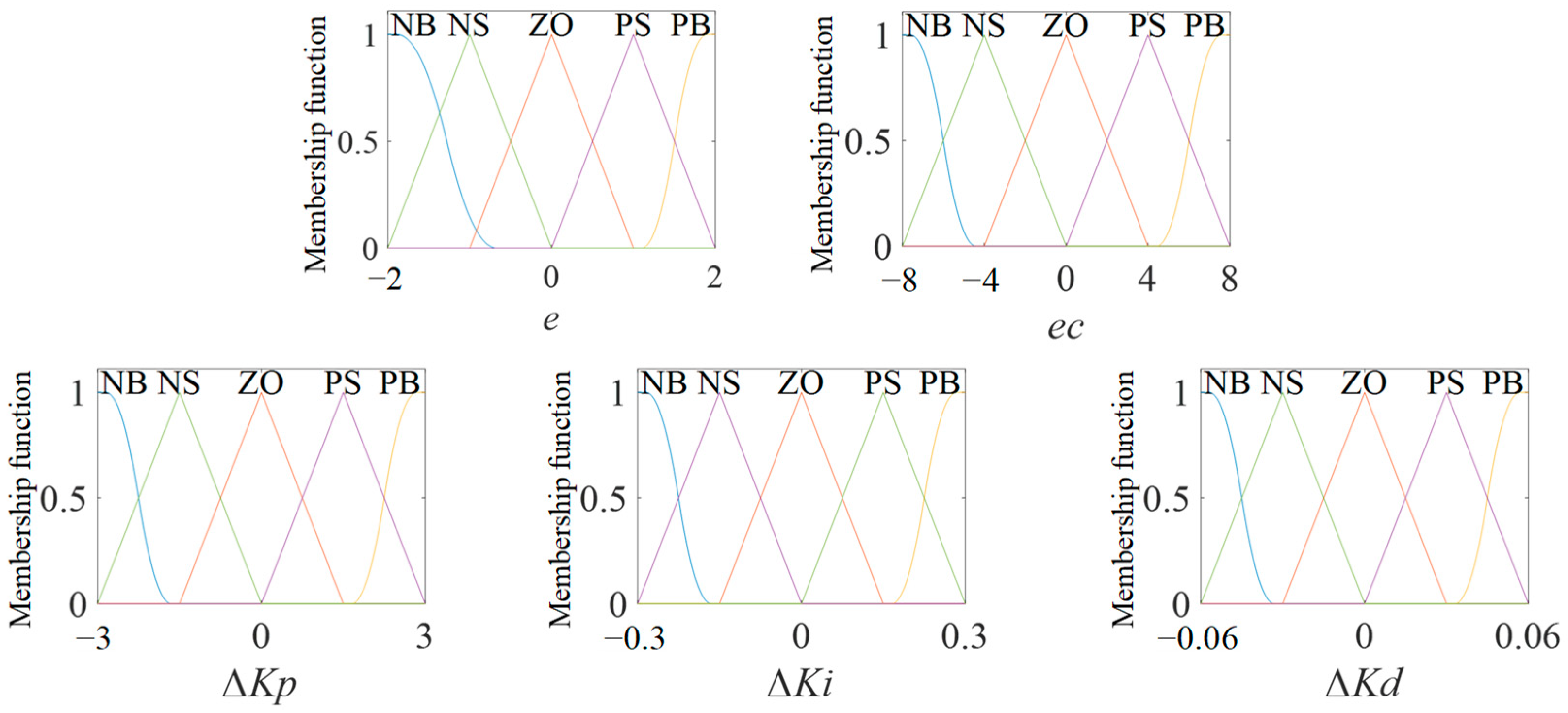
Kd were defined as [−3,3], [−0.3,0.3] and [−0.06,0.06], respectively. The fuzzy domain represents the value range of the variable. Each variable was divided into intervals and NB, NM, ZO, PS and PB were used to represent each fuzzy subset. The definition of the membership function in this paper is shown in
Figure 9. The role of the membership function is to find the membership of the variable and perform fuzzy reasoning based on the membership.
- (2)
Fuzzy rule making
Fuzzy rules mainly determine the corresponding relationship between input and output, which is determined by operating experience and expert knowledge. The fuzzy control rules used in this paper are shown in
Table 2,
Table 3 and
Table 4.
- (3)
Defuzzification
The data calculated by fuzzy rules need to be defuzzied. The common methods of defuzzification are the weighted average method, centroid method and maximum membership method [
25]. In this study, the centroid method was used for defuzzification. The formula can be expressed as:
where
xi is the element in the domain and
μ(
i) is the membership weighting coefficient of fuzzy set.
4.2. Simulation Result Analysis
In this study, the controller was established in MATLAB/Simulink (R2019b) and co-simulated with the shift model established in Adams. The key simulation parameters are shown in
Table 5.
In the case of position control, the target positions at each stage are shown in
Table 6. The single-actuator shift and the dual-actuator shift were compared. The same control method, control parameters and control strategy were used in the shift process, and the simulation results are shown in
Figure 10. The single-actuator shift showed a 36 m/s
3 shock at F, the shock degree of the dual-actuator shift at E was 28 m/s
3, and the shock degree at G was 20 m/s
3. Under the same control method, the shock degree of the dual-actuator shift was 28.57% lower than that of the single-actuator shift. Because the velocity of the sleeve of the dual-actuator shift at A to B was faster than that of the single-actuator shift due to the absence of mutual interference, the dual-actuator shift at E had a greater shock than the single-actuator shift, which could be avoided by control in the later stage. Points F and G are at the beginning of the tooth-shifting stage and have higher shocks, but since there is no interference between the left and right sides of the dual actuator, the shock at point G is lower than that at point F. On the whole, the dual-actuator shift eliminates the mutual interference problem of the single-actuator shift, and the shock of the dual-actuator shift is smaller under the same control method.
In order to verify the effectiveness of the staged fuzzy PID controller proposed in this paper, it was compared with the staged PID control [
26,
27] and the staged BP neural network PID control [
28,
29]. The simulation results are shown in
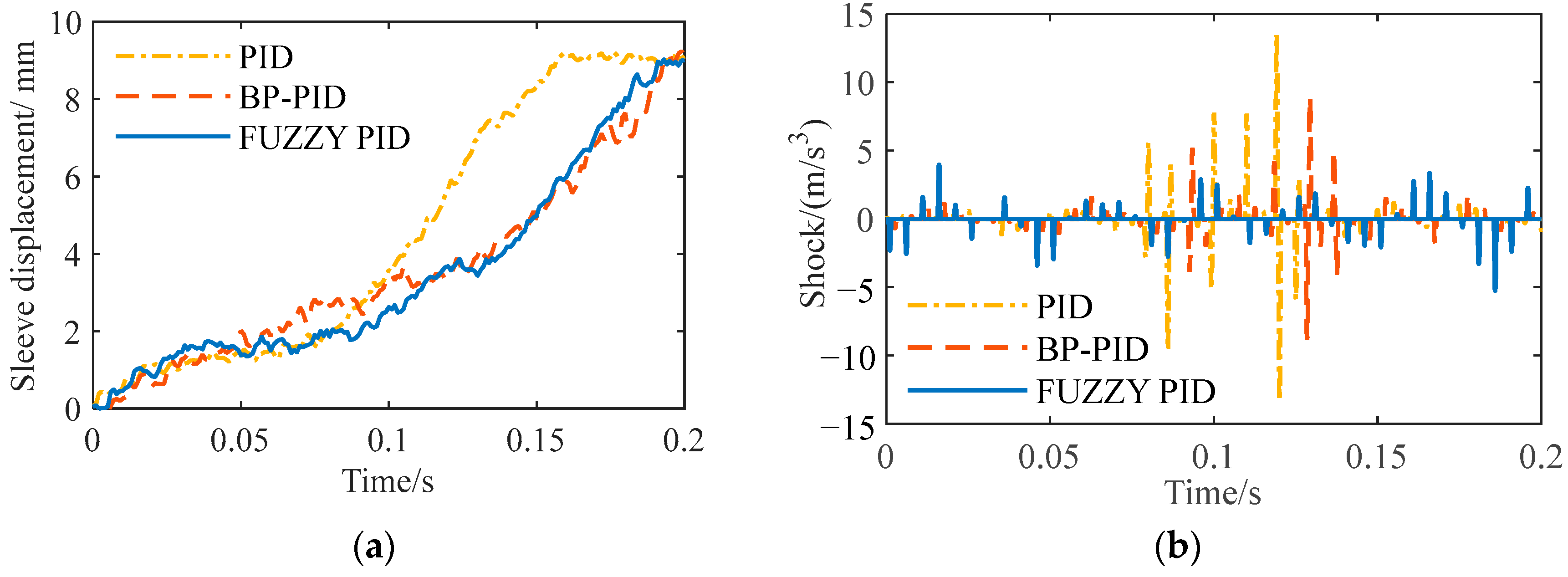
Figure 11. From
Figure 11a, it can be seen that the three control methods all completed the shift within 200 ms, meeting the shift requirements [
30]. The shift time of the staged PID control was 115 ms, the shift time of the staged BP neural network PID control was 135 ms and the shift time of the staged fuzzy PID control was 175 ms. The maximum shock generated by the staged PID control was about 13 m/s
3, the maximum shock generated by the staged BP neural network PID control was about 10 m/s
3 and the maximum shock generated by the staged fuzzy PID control was about 5 m/s
3. Compared with the other two methods, it was reduced by 61.54% and 50%. The staged PID generated 0.84 J of the slipping friction work, the staged BP neural network PID control generated 0.39 J and the staged fuzzy PID control generated 0.58 J. The shifting time of the staged fuzzy PID control is longer, mainly because the shifting ring and gear stages take up a longer time. These two stages affect the shock degree and slipping friction work. Therefore, the shock degree generated was greatly reduced compared with the other two methods, and the slipping friction work was also significantly reduced compared with the staged PID control. The original intention of the dual-actuator shifting design is to reduce shifting shock. Therefore, the staged fuzzy PID control is more suitable for dual-actuator shifting, which produces the smallest shock and has moderate slipping friction work, which can extend the service life of the synchronizer.
5. Actual Vehicle Test and Result Analysis
In this paper, the control effect of the dual-actuator shift was verified by a real vehicle test. The test equipment included a host computer, dSPACE controller, dual-mode coupling drive electric vehicle and high-precision integrated positioning system. The test equipment diagram is shown in
Figure 12.
This paper verified the effectiveness of the dual actuator combined with the staged fuzzy PID control compared with the other two control methods. The test vehicle ran on a straight road, and adopted a centralized drive in the initial stage. When the speed reached 30 km/h, the drive mode was switched to a distributed drive. The test results are shown in
Figure 13.
It can be seen that the staged PID control has a short shift time, but the maximum shock is 14 m/s
3. The shift time of the staged BP neural network PID control is basically the same as that of the staged fuzzy PID control, but the shock is reduced by 64% and 50%, respectively, by using the staged fuzzy PID control, and the shift quality is obviously improved. The comparison of different control methods is shown in
Table 7. The test results are basically consistent with the simulation results, which proves the effectiveness of the staged fuzzy PID control.


