Abstract
External-rotor dual-armature flux-switching PM (ER-DA-FSPM) machines have high torque density and decent fault tolerance, making them promising candidates for in-wheel machine applications in electric vehicles. The torque output and optimal design parameters of ER-DA-FSPM machines are affected by the stator/rotor torque ratio, which is the focus of this paper. Firstly, this paper analyzes airgap flux density harmonics of ER-DA-FSPM to provide a clear insight into the torque-generation mechanism. Then, this paper investigates the influence of torque ratio on average torque under the same copper loss. It is found that the average torque decreases with torque ratio increasing due to the reduction of the positive torque component generated by the sixth airgap field harmonics and the rise in the negative torque component from the eighth harmonics. Moreover, this paper also provides the optimal parameter recommendation to guide the machine design. The split ratio should increase, and the arc of PMs should decrease for a larger torque ratio, whilst the other parameters are hardly influenced. Next, this paper makes a comparison among the ER-DA-FSPM machine, external rotor flux-switching PM (ER-FSPM) machine, and surface-mounted PM (ER-SPM) machines. It shows that the ER-DA-FSPM machine, with the torque ratio being 2, can lead to a much larger total torque. In addition, in the event of rotor winding failure, which is more possible due to the existence of slip rings than stator winding failure, the stator can still provide an average torque larger than that of ER-SPM machine and 92.0% that of the ER-FSPM machine, respectively. Finally, the theoretical analysis is verified by the experiments.
1. Introduction
Electric vehicles have gained significant attention and support from governments worldwide due to their notable advantages, such as high efficiency and low emissions [1,2,3,4]. The in-wheel machine drive is one of the typical driving modes of electric vehicles. In-wheel machines provide a direct drive to the wheels. This driving mode eliminates the need for a traditional transmission system and has high efficiency and a simplified structure [5,6,7]. It also has the characteristics of rapid torque response and accurate control, enabling more effective active vehicle safety control [8,9]. Because in-wheel machine needs to be integrated into the wheel hub, it is limited by the hub’s size and cannot be expanded at will to improve output torque. Therefore, the improvement of torque density for in-wheel machines is a research hotspot [10,11,12]. In addition, since safety is the primary consideration when the vehicle is running, it is essential to ensure high reliability under various working conditions and prevent accidents caused by motor failure. As a result, enhancing the torque density and reliability of in-wheel machines with external rotors has become a prominent area of research.
The flux-switching permanent magnet (FSPM) machine is known for high magnetic density, torque density, and efficiency [13,14,15]. In applications with low speed and high torque, such as electric vehicles, the external rotor structure is particularly advantageous for direct-drive in-wheel machines [10,16,17]. Due to the requirements of higher torque and power to meet the vehicle’s acceleration performance, climbing ability, and high-speed cruise, many methods were proposed to improve torque density. Various FSPM machines have been proposed with different core structures like C-Core, E-Core, and Multi-Teeth design [18,19,20] to improve the torque output. However, these designs have lower space utilization than the traditional U-Core structure, which limits the further improvement of torque density. Using V-shaped magnets [11,21] is another way to improve the torque output. However, this structure has large cogging torque and back electromotive force harmonics [21]. In [22], the design of wedge-shaped stator teeth and magnets was proposed to expand the stator slot area, which greatly increases the torque density. In addition, the external rotor FSPM (ER-FSPM) machine with this design can exhibit negligible torque ripples. However, all of these designs cannot essentially solve the competition of the magnets and slot area.
Improving fault tolerance of the FSPM machine is also a research hotspot. The traditional three-phase winding configuration cannot satisfy the high-reliability requirements. In [23,24], the modular FSPM machine can also increase fault tolerance, but the amount of permanent magnets is half that of the traditional FSPM machine, which limits the torque output. Increasing the number of winding phases can also improve fault tolerance. When the machine fails in one or more phases, it continues to operate through the remaining healthy phases. In addition, machines with more phases have lower mutual inductance. Consequently, the healthy phases are less influenced by the faulty phases, which means such machines have better fault tolerance [25]. However, windings with different phases compete for confined space in the stator slots. Therefore, improving the fault-tolerant capability limits the increase in torque density.
To improve torque density and fault tolerance simultaneously, some research has proposed a double-stator FSPM machine. Because each stator has a set of windings, this machine possesses good fault-tolerant capability and torque density [26,27]. However, this structure is relatively complex, which brings challenges to the production, and the double airgap structure has a larger equivalent airgap length, which limits the increase of torque [28]. To keep the single airgap structure and double-winding configuration, the dual-armature flux-switching permanent magnet (DA-FSPM) machine was proposed, which adds another set of windings on the rotor in the internal-rotor FSPM [29,30]. With two sets of windings, stator and rotor slot areas are specially designed to generate the same average electromagnetic torque, which enables the machine to maintain a certain torque output when one set of windings fails. Moreover, the addition of rotor windings optimizes the use of the machine’s internal space, increasing the electrical loading and thereby significantly enhancing torque density.
The dual-armature structure can also be applied to ER-FSPM machines to improve the torque density and fault-tolerant capability of in-wheel machines, which is rarely found in the previous literature. In conventional ER-FSPM machines, since the armature winding and the PMs are both located on the stator and compete with each other in space, they may cause significant magnetic saturation [17]. Magnetic saturation can impact the performance of the machine, such as the decrease of output torque and the increase of torque ripple and machine temperature [31,32,33]. The double-winding structure also reduces magnetic saturation under the same copper loss. Moreover, with part of the windings moved to the external core, the heat dissipation performance of the FSPM machine can be improved [34]. In addition, PM overheating and irreversible demagnetization can also be suppressed [33].
However, in order to meet the requirements of different operating conditions of electric vehicles, such as frequent acceleration and deceleration, the rotor of the in-wheel machine needs to have small inertia [35], which limits the weight of the rotor’s windings and core. Moreover, slip rings in the rotor can make the failure probability of the rotor winding greater than that of the stator winding. The torque generated by the stator windings should be improved to guarantee relatively large output torque under most fault-tolerant operating conditions. Therefore, the assumption of rotor winding providing the same average torque as the stator winding cannot be applicable to in-wheel ER-FSPM machines for EVs [30]. Research concerning how the ratio of the stator torque to rotor torque influences the machine’s performance is needed. It can guide the design of external-rotor dual-armature flux-switching magnet (ER-DA-FSPM) machines, particularly those requiring high reliabilities.
In this paper, the influence of torque ratio on the electromagnetic performance in ER-DA-FSPM machines is investigated. Firstly, the MMF-permeance model is established for airgap field modulation. Next, this paper investigates the influence of torque ratio on total average torque through the analysis of dominating field harmonics generating torque. The characteristics of optimized dimensional parameters with torque ratio are analyzed subsequently. Then, the comparison is made between ER-FSPM, ER-DA-FSPM, and ER-SPM machines about torque density and fault-tolerant capability. Finally, an experimental validation is conducted.
2. Harmonic Analysis of Airgap Fields
Before the influence of stator/rotor torque ratio on the torque performance of the ER-DA-FSPM machine is investigated, the torque-generation mechanism is analyzed from the point of airgap flux density by the MMF-permeance model.
2.1. Topology of ER-DA-FSPM Machine
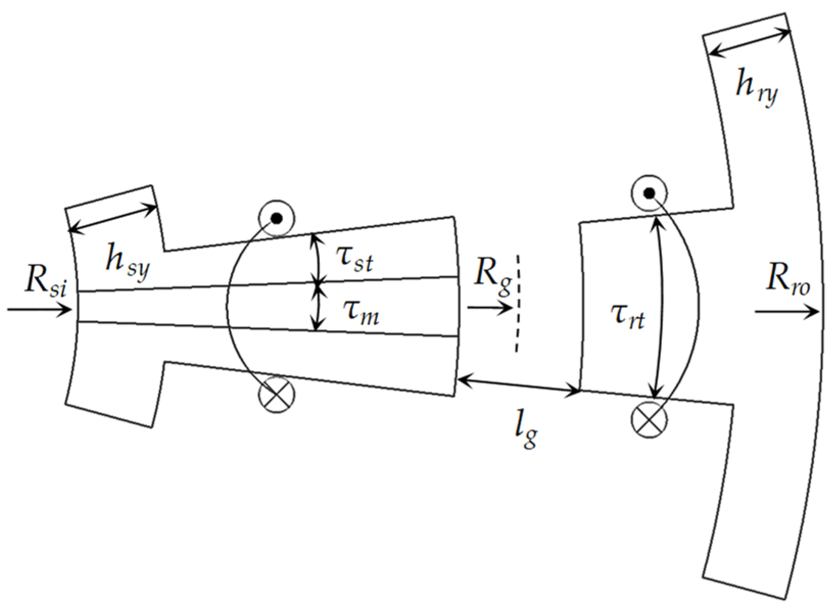
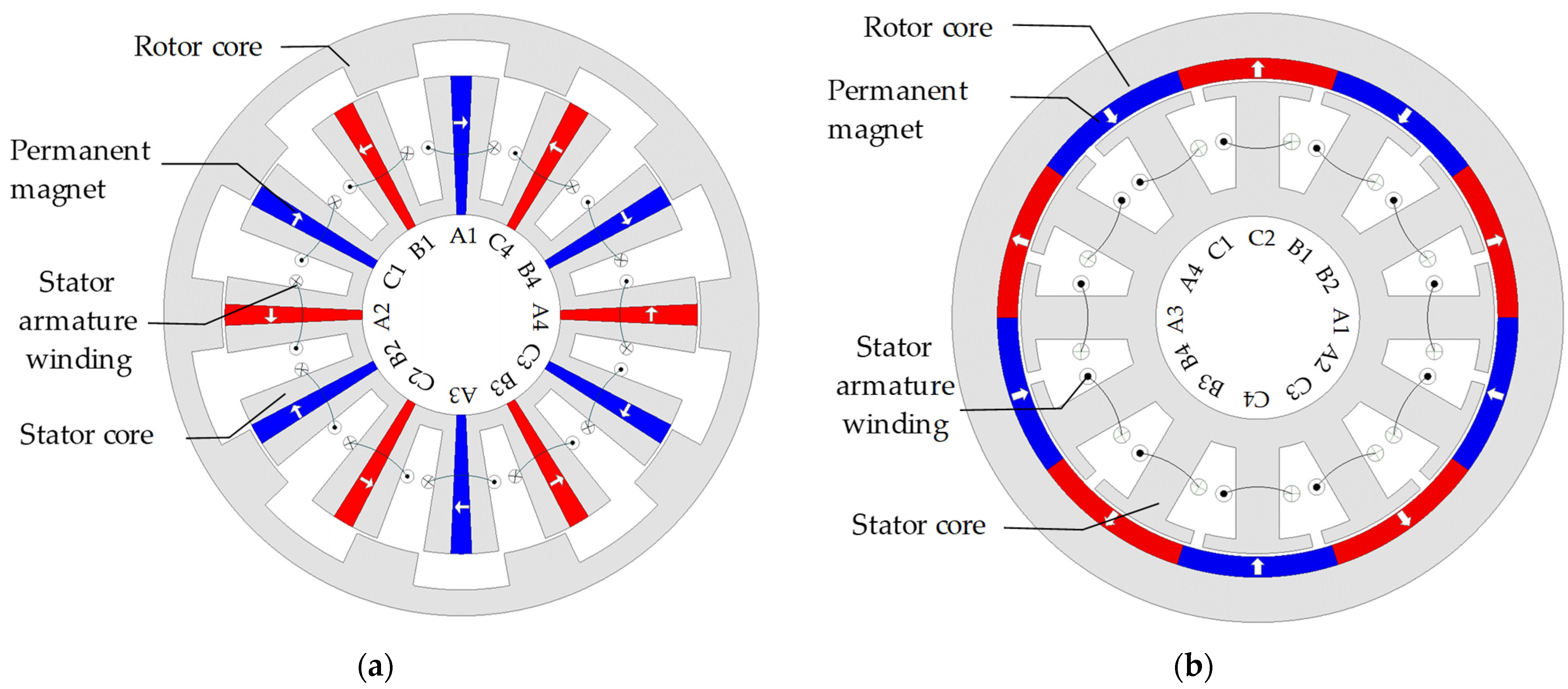
Figure 1 shows the topology of the investigated ER-DA-FSPM machine. Figure 2 shows the diagram of key design parameters, and Table 1 provides the parameter values. Compared with the ER-FSPM machine, the ER-DA-FSPM machine has a much higher torque density due to the utilization of the rotor slot area. In addition, the ER-DA-FSPM machine has the potential for fault-tolerant operation as it has two sets of armature windings. For the investigated ER-DA-FSPM machine, both the stator and rotor use a double-layer winding design for higher torque density [36]. Although single-layer winding configuration can better limit the short-circuit current than double-layer winding to further improve the fault tolerance [37], its resulting torque ripple is higher [38,39]. In addition, it is noteworthy that the investigated machine chooses five phases for the rotor windings to achieve the largest winding factor with a relatively low inverter cost. Additionally, it has been found that a rectangle is not the optimal magnet shape for the ER-FSPM machines [22]. The stator slot area is compressed by PMs near the stator yoke, thus constraining the space for stator armature. Therefore, the ER-DA-FSPM machine in this paper adopts wedge-shaped PMs to further improve torque density.
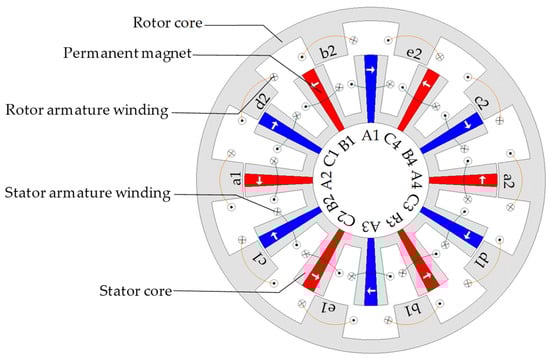
Figure 1.
Topology of ER-DA-FSPM machine.
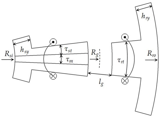
Figure 2.
Diagram of key parameters of ER-DA-FSPM machine.

Table 1.
Parameters of ER-DA-FSPM machine.
2.2. Harmonic Analysis of Airgap Flux Density
When the machine has two sets of winding, the airgap magnetic fields are generated by three sources, i.e., PMs, stator windings, and rotor windings, making the fields complicated [40,41]. It has been proven that the MMF-permeance model is effective and concise for qualitative research [42,43] of airgap fields. Although the airgap flux density from PM or stator armature reaction for ER-DA-FSPM is similar to that of the ER-FSPM machine, the rotor-armature reaction has not been analyzed, which is the main focus of this section. In this paper, the MMF-permeance model is developed neglecting the end effect. In addition, the saturation of steel lamination is also not considered. The flux lines are perpendicular to the steel-lamination surface, which keeps the tangential component of the airgap fields at zero [42].
Figure 3 shows the airgap permeance model accounting for stator saliency. When the leakage flux is neglected, the airgap permeance accounting for stator saliency mainly changes with the permeability along the stator surface shape [44,45,46]. In addition, the permeability of air, copper windings, and permanent magnets are close to vacuum permeability, whilst the permeability of the core is assumed to be infinite. Therefore, the airgap permeance is a rectangular wave with an offset. In Figure 3, P10 and P1 are the DC component and peak–to-peak value of the permeance model. ps, θ1, and θ2 are the PM pole-pair number, the half-arc of PM, and the half-arc of PM plus stator tooth, respectively.
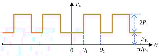
Figure 3.
Airgap permeance model of ER-DA-FSPM accounting for stator saliency.
The Fourier series expansion of this model can be expressed as (1), in which M1n and S1 are the Fourier coefficients [41,42].
The rotor phase currents can be described as
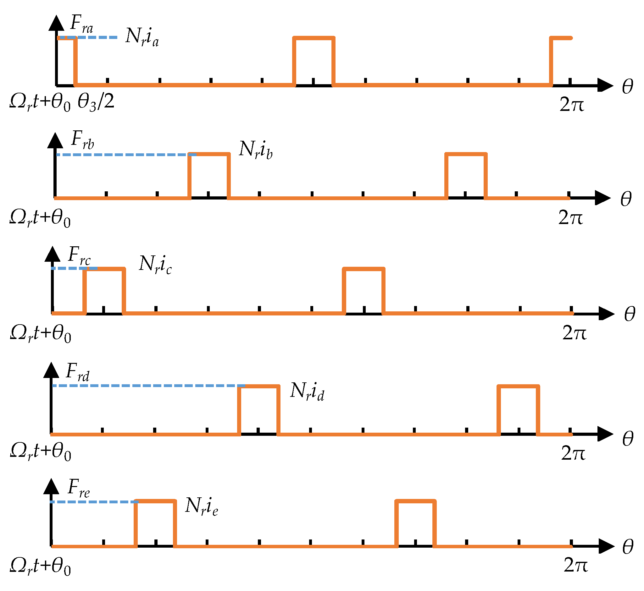
where Ir is the RMS phase current of rotor windings and Ωr is the mechanical rotor speed. The airgap MMF of the rotor-armature reaction in the ER-DA-FSPM machine accounting for the rotor saliency is presented in Figure 4. Nr is the number of turns per rotor coil, θ0 is the initial rotor pole position, and θ3 is the arc of the rotor tooth. For the rotor phase a, the Fourier series expansion of MMF can be expressed as
where tr is the rotor tooth number, and
According to (2), MMF of rotor phase a can be rewritten as
It can be found that the MMF of the rotor phase a contains two components with different frequencies. MMF for other rotor windings can be obtained accordingly. Therefore, the total MMF by all rotor windings can be expressed as
When m = 5l, m = 5l − 1, and m = 5l − 4, the MMF components with each frequency from different rotor phases are cancelled out due to the current phase difference of the five rotor phases. When m = 5l − 2, the MMF components with frequency (ps − 2m)Ωrt are offset, whilst the components with frequency (ps + 2m)Ωrt are in the same phase. Therefore, the total MMF can be obtained as
where
Similarly, when m = 5l − 3, the components with frequency (ps + 2m)Ωrt, are offset whilst the components with frequency (ps − 2m)Ωrt are in the same phase. Therefore, the total MMF can be expressed as
Hence, the airgap MMF of rotor armature reaction can be summarized as
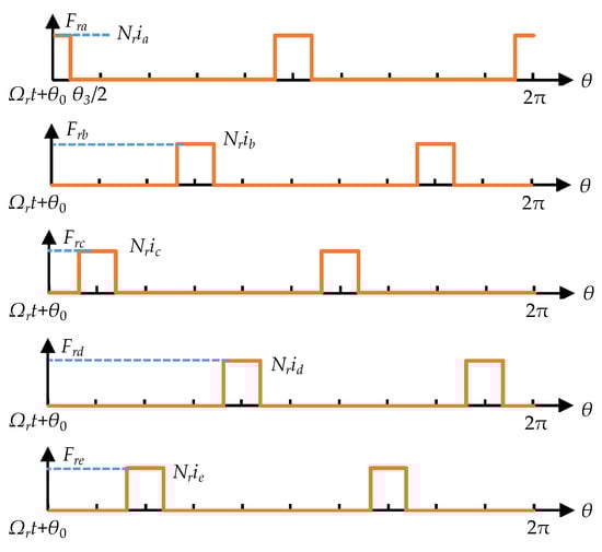
Figure 4.
Airgap MMF of rotor-armature reaction in ER-DA-FSPM machine accounting for the rotor saliency.
Combining the permeance model, when m = 5l − 3, the rotor-armature reaction airgap flux-density distribution Br can be calculated as
when m = 5l − 2, Br can also be expressed by (11) with a negative sign applied to m.
Based on the above analysis, the characteristics of spatial harmonics from the rotor armature reaction are listed in Table 2. The open-circuit and stator armature airgap flux density can be obtained from [42], which are shown in Table 3 and Table 4, respectively, where i and k are nonnegative integers, and q and r are positive integers. It can be found that the pole-pair numbers of stator- and rotor-armature reaction airgap magnetic fields are consistent with those |(2i − 1)ps ± ktr| of open-circuit airgap magnetic fields.
Table 2.
Characteristics of rotor-armature flux-density components.
Table 3.
Characteristics of open-circuit flux-density components.
Table 4.
Characteristics of stator-armature flux-density components.
2.3. FE Validation
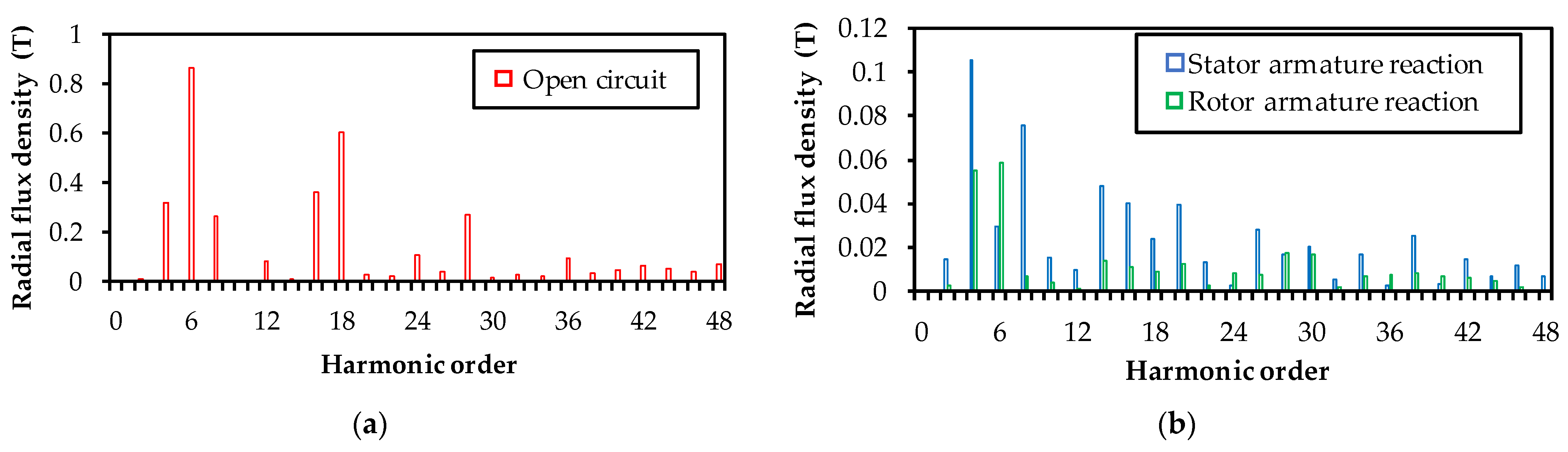
In this part, the above analysis is validated by an FE simulation on the investigated ER-DA-FSPM machine shown in Figure 1. The stator and rotor RMS phase currents are 6.43 A and 2.02 A, respectively. Under such conditions, the ratio of stator torque to rotor torque, i.e., Ts/Tr, is 2. The FE-predicted radial airgap flux harmonics of the ER-DA-FSPM machine are presented in Figure 5. It can be found that parts of the dominating rotor-armature reaction airgap field harmonics have pole-pair numbers 4 and 6 [2m, when (l = 1, n = 2, 3)] without the modulation of stator saliency. The other dominating harmonics have pole-pair numbers 28 and 30 [2(nps + m) when (n = 1, m = 8 and n = 2, m = 3)] due to the modulation of the salient stator to the rotor armature reaction MMF, which matches well with the results by the MMF-permeance model.
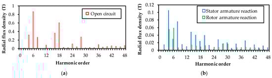
Figure 5.
FE-predicted radial airgap field harmonics. (a) Open circuit. (b) Armature reaction.
3. Influence of Stator/Rotor Torque Ratio
This section investigates the influence of the stator/rotor torque ratio on the torque performance of the ER-DA-FSPM machine, before which the ER-DA-FSPM machine is optimized aimed for maximum average torque under different Ts/Tr.
3.1. Parameter Optimization
In order to make a fair comparison, the key dimensional parameters of the investigated ER-DA-FSPM machine are first optimized. Since this paper focuses on the optimization of dimensional parameters for ER-DA-FSPM machines, the core and PM materials are selected as commonly used ones and kept unchanged, which is shown in Table 1. As for the dimensional parameters, the outer and inner diameters, and the axis length, they are usually constrained by the application space of ER-DA-FSPM machines. In addition, the airgap length is limited by the manufacturing and assembly process. Therefore, these parameters are also fixed in the optimization. Hence, the most influential parameters and their initial values are selected in Table 5, which can determine machine-dimensional characteristics, as well as electromagnetic performance. In addition, during optimization, the total copper loss of stator and rotor windings is fixed at 24 W, considering the temperature limit of winding insulation.
Table 5.
Initial value of key dimensional parameters of ER-DA-FSPM machine.
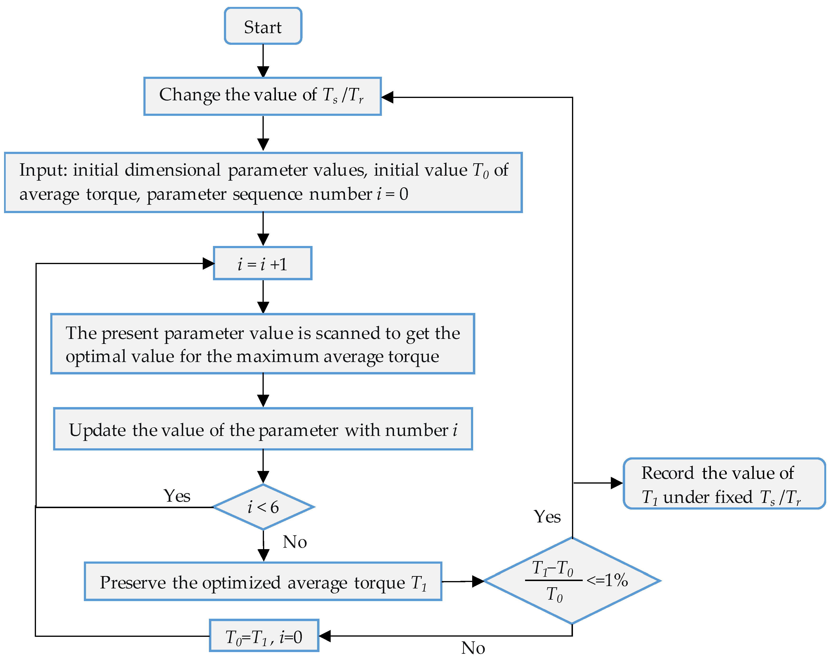
The optimization of the ER-DA-FSPM machine is conducted using a sequential approach, as shown in Figure 6. Firstly, the optimization should identify one fixed value for Ts/Tr. Then, the investigated parameters are optimized one after another. When one optimal parameter is found, it is used as the basis for the optimization of the next parameter. It should be noted that when dimensional parameters vary, the areas of stator and rotor slots also change. Therefore, stator- and rotor-armature currents should be adjusted to keep the fixed copper loss [47]. In addition, according to [30], the parameter-optimization order has little effect on the sequential optimization result. In this article, the order goes in Table 5. After the nth cycle of optimization, the average torque Tn is compared with Tn−1 of the last cycle. If (Tn − Tn−1)/Tn ≤ 1%, the optimization ends and Tn is regarded as the maximum average torque for the current Ts/Tr. The maximum average torque for other Ts/Tr can be obtained by repeating the above steps.
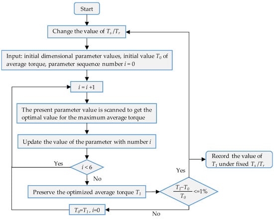
Figure 6.
The flow chart of sequential optimization.
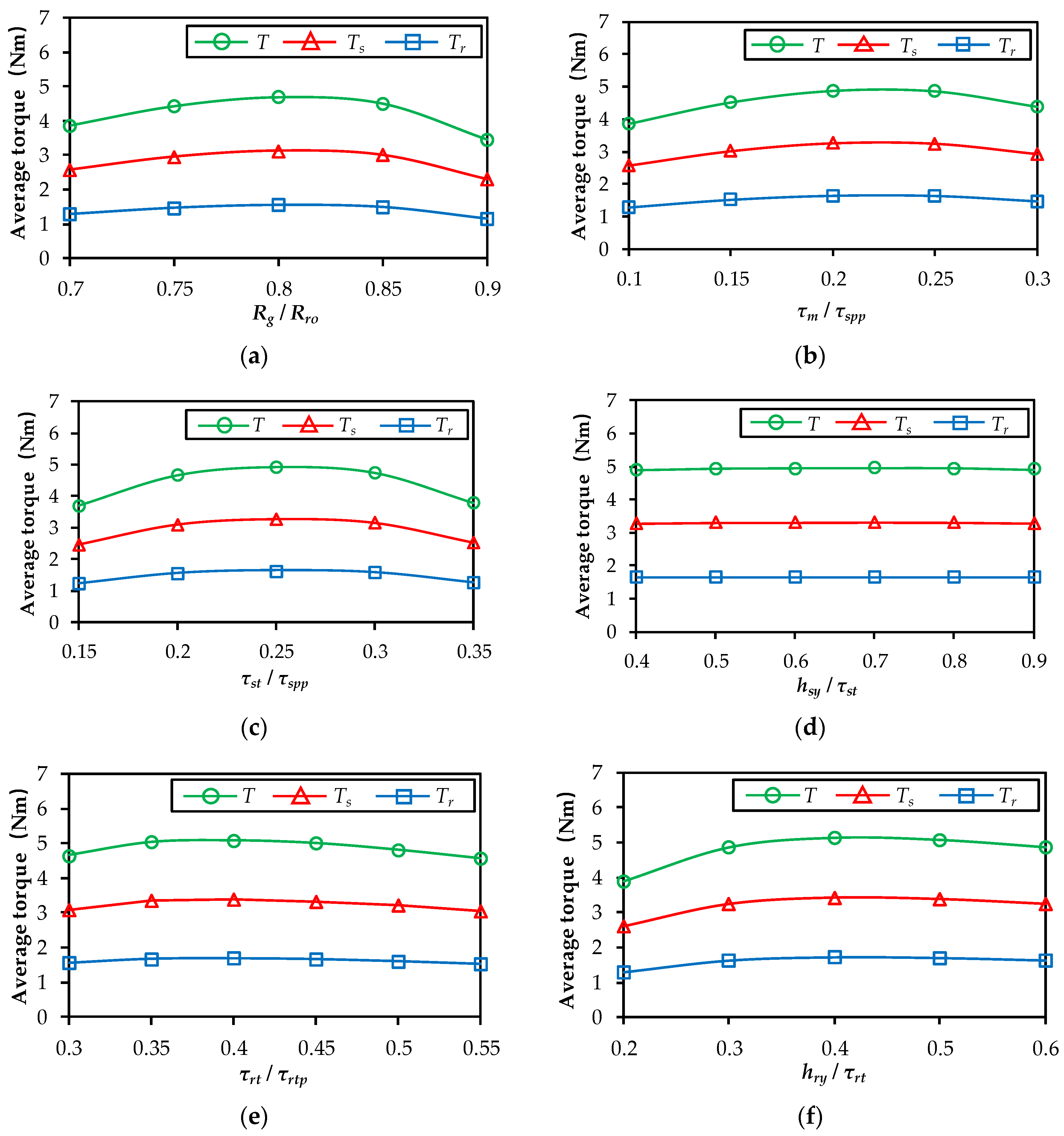
The first cycle of optimization of the six different key dimensional parameters when the Ts/Tr equals 2 is shown in Figure 7, where T is the total torque. For each parameter, the value range around the optimal value is shown for clear visibility. It can be found that, when each parameter increases, a maximum average torque can be achieved due to the mutual constraints between armature and PMs [30]. The maximum average torque increases from 4.80 Nm to 5.15 Nm. For the next cycle, the increase of maximum average torque does not exceed 1%. Thus, 5.15 Nm is the maximum average torque under Ts/Tr = 2. The optimization process under the other Ts/Tr is similar and, thus, neglected. In addition, the sensitivity of average torque to these key parameters can also be observed from Figure 7, which is defined as
where Tmax is the peak average torque when each key parameter is optimized, and Tmin is the minimum average torque when each key parameter deviates from the optimal value from −0.05 to 0.05. The sensitivities of average torque to the following six key parameters are 8.97%, 7.34%, 8.06%, 0.08%, 1.77%, and 4.32%, respectively. It can be found that Rg/Rro has the greatest influence on the average torque, whilst hsy/τst almost has no effect.
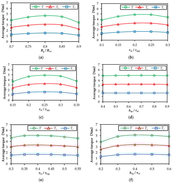
Figure 7.
Optimal value of dimensional parameters when Ts/Tr = 2. (a) Rg/Rro. (b) τm/τspp. (c) τst/τspp. (d) hsy/τst. (e) τrt/τrtp. (f) hry/τrt.
3.2. Influence of Stator/Rotor Torque Ratio on Maximum Average Torque
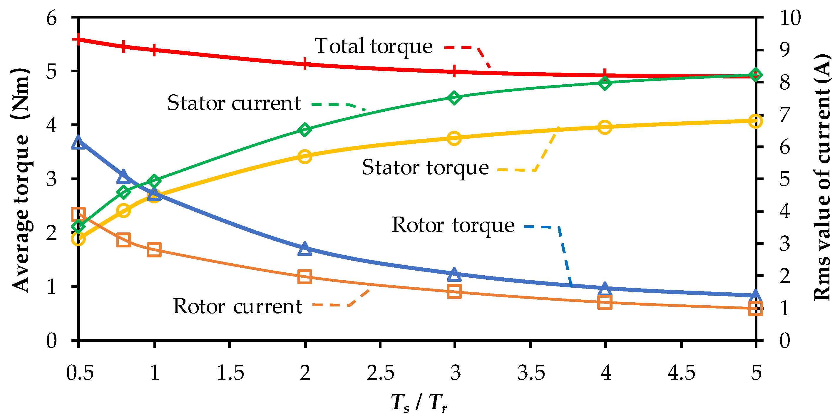
After optimization, the average torque and current under different values of Ts/Tr are shown in Figure 8. It can be found that when Ts/Tr increases, the total average torque decreases with a decline rate. This is because the stator winding of ER-DA-FSPM works as a traditional ER-FSPM machine, whilst the rotor winding works as a spoke-type interior PM (IPM) machine. The former usually leads to smaller torque density. To achieve increasing Ts/Tr, more copper loss should be allocated to the stator windings, i.e., the ER-FSPM machine, which thus makes the total average torque decrease.
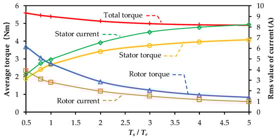
Figure 8.
Maximum average torque under different Ts/Tr.
The paper also explains this phenomenon from the point of airgap field harmonics. The instantaneous electromagnetic torque T(t) excited by radial and tangential field harmonics can be described as
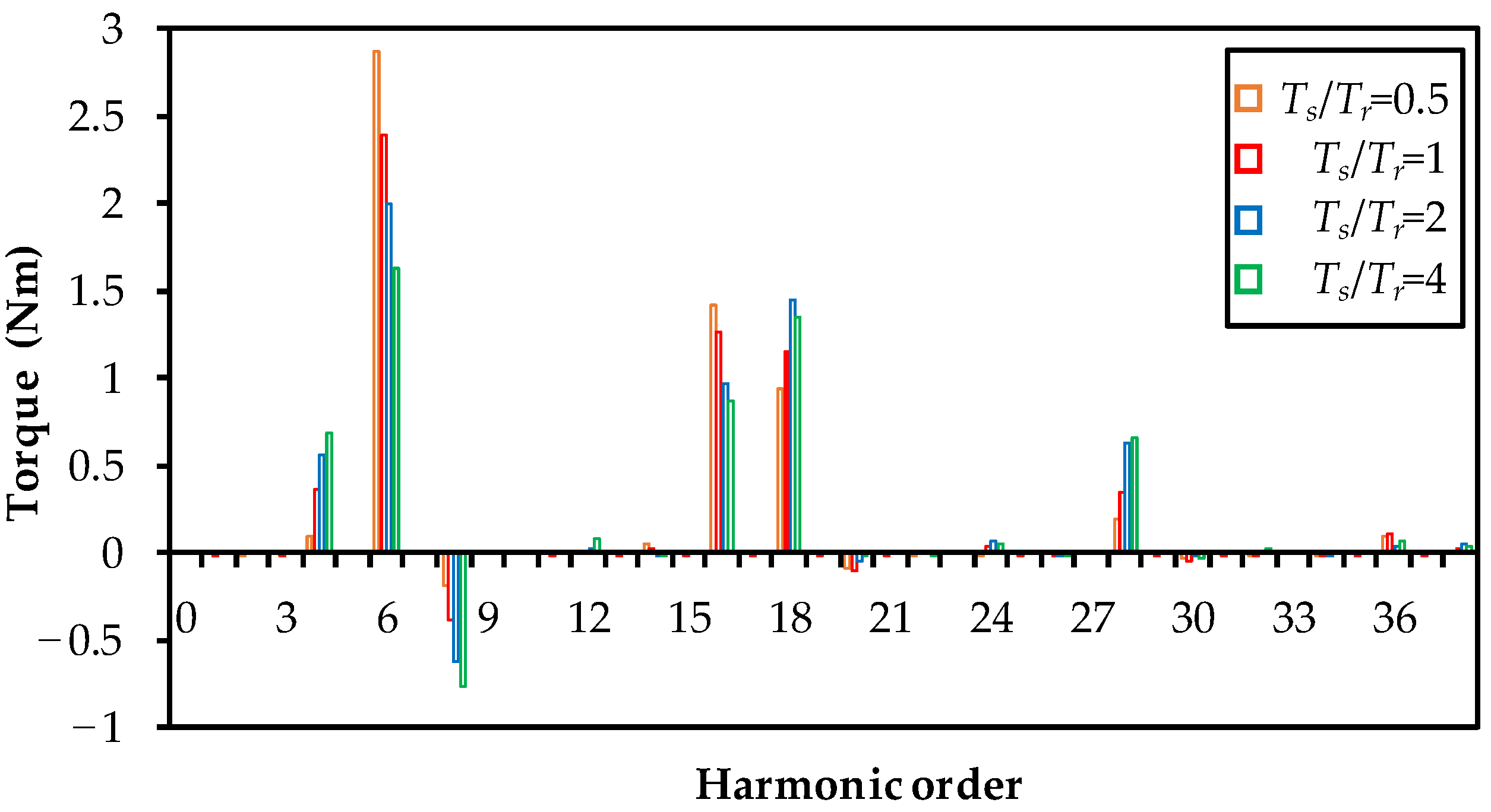
where L is the active length, R is the airgap radius, and Brn and Btn are the nth harmonic magnitudes of the airgap flux-density radial and tangential components, respectively, and θrn and θtn are the corresponding phases separately. By (5), the torque contribution from each dominant airgap flux density harmonic can be analyzed. The radial and tangential components of airgap flux density are obtained by the FE method at a specific time when the transient torque equals the average torque. Figure 9 shows the torque component contributed by each field harmonic when Ts/Tr = 0.5, 1, 2, and 4. It can be found that the 6th (ps), 16th (ps + tr), and 18th (3ps) are the dominating airgap field harmonics contributing to the electromagnetic torque when Ts/Tr = 0.5 and 1. When Ts/Tr = 2 and 4, the 4th (−ps + tr), 8th (3ps − tr), and 28th (3ps + tr) also lead to non-negligible torque components. The reason why the total average torque decreases with the increase of Ts/Tr is the decreasing magnitude of the positive sixth component and the increasing magnitude of the negative eighth component. Moreover, the decline rate of the torque reduction can be attributed to the increasing magnitudes of the positive 4th, 18th, and 28th components.

Figure 9.
Torque contribution of different airgap field harmonics.
3.3. Influence of Stator/Rotor Torque Ratio on Parameter Design
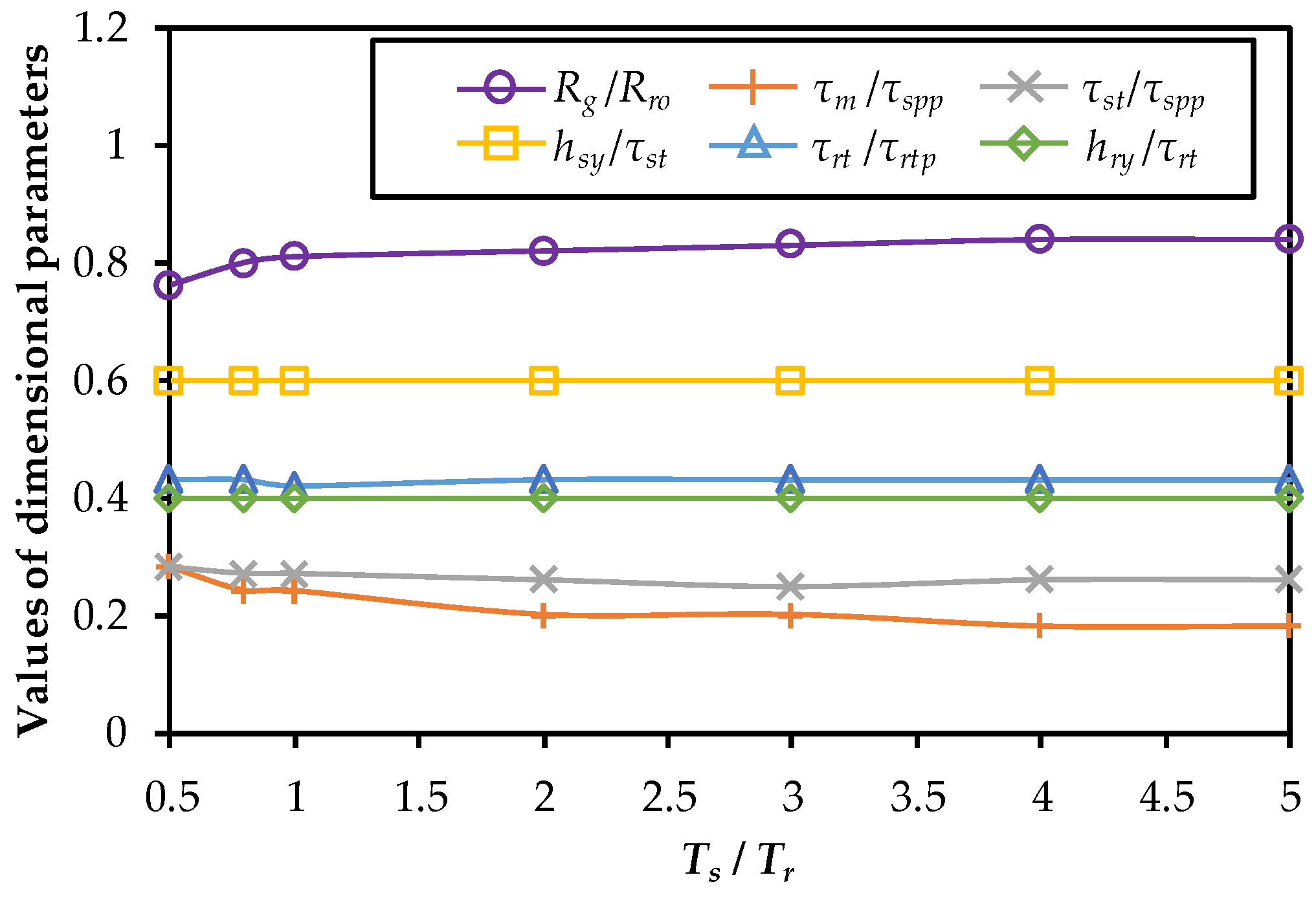
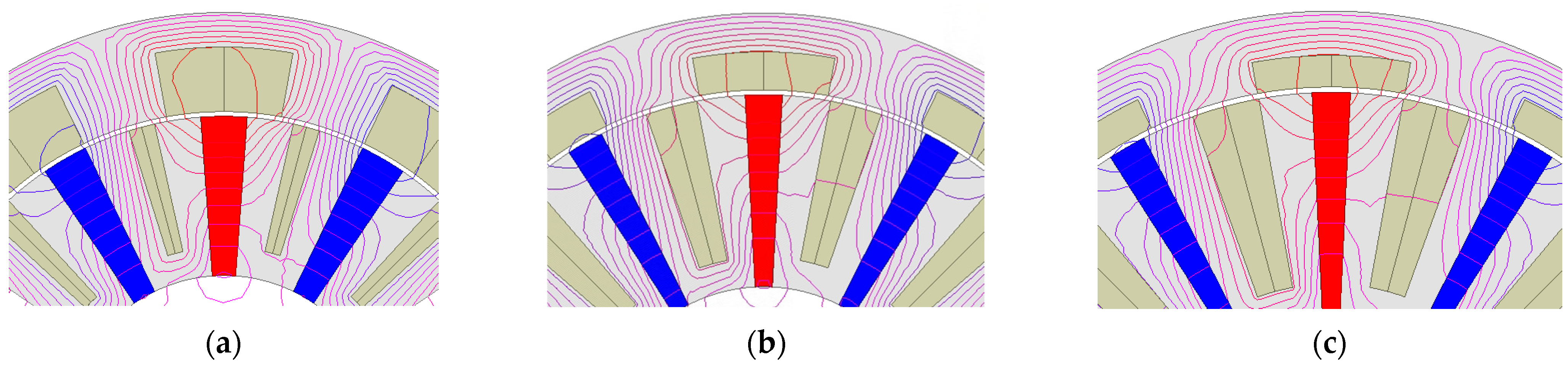
The variation of optimized key dimensional parameter values with Ts/Tr is shown in Figure 10. It can be found that τst/τspp, hsy/τst, τrt/τrtp, and hry/τrt almost do not change under different Ts/Tr. However, the optimized value of Rg/Rro increases, whilst the value of τm/τspp decreases separately with the increasing Ts/Tr. The larger split ratio is preferred because the increasing space for the stator winding and PMs is needed. The selection of τm/τspp is also influenced by the split ratio. For larger Ts/Tr, the rising split ratio increases the PM width, which is perpendicular to the magnetization direction, as shown in Figure 11. It improves the open-circuit flux density yet has a low rate. Under such conditions, reducing τm/τspp to increase the electric load is more effective in improving the torque density.
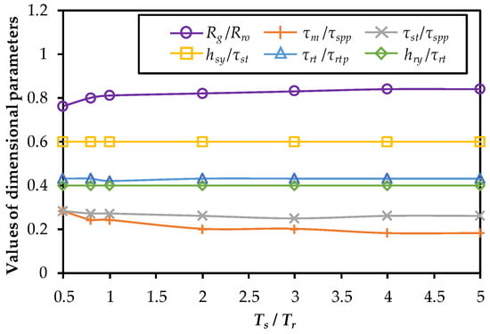
Figure 10.
Optimized dimensional parameters under different Ts/Tr.
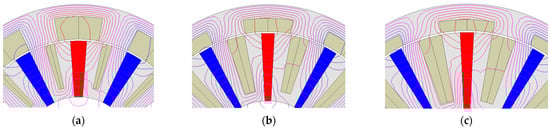
Figure 11.
Topology and open-circuit flux lines under different τm/τspp. (a) τm /τspp = 0.27 when Ts/Tr = 0.5, (b) τm /τspp = 0.2 when Ts/Tr = 2, (c) τm /τspp = 0.18 when Ts/Tr = 4.
4. Advantage of ER-DA-FSPM Machine
To effectively illustrate the superior torque density and fault-tolerant capability of the ER-DA-FSPM machine, a comparative analysis is conducted with the ER-FSPM and external-rotor surface-mounted PM (ER-SPM) machines, which are shown in Figure 12.

Figure 12.
Topology of machines for comparison. (a) ER-FSPM machine. (b) ER-SPM machine.
4.1. Comparison of Average Torque for Different Machines
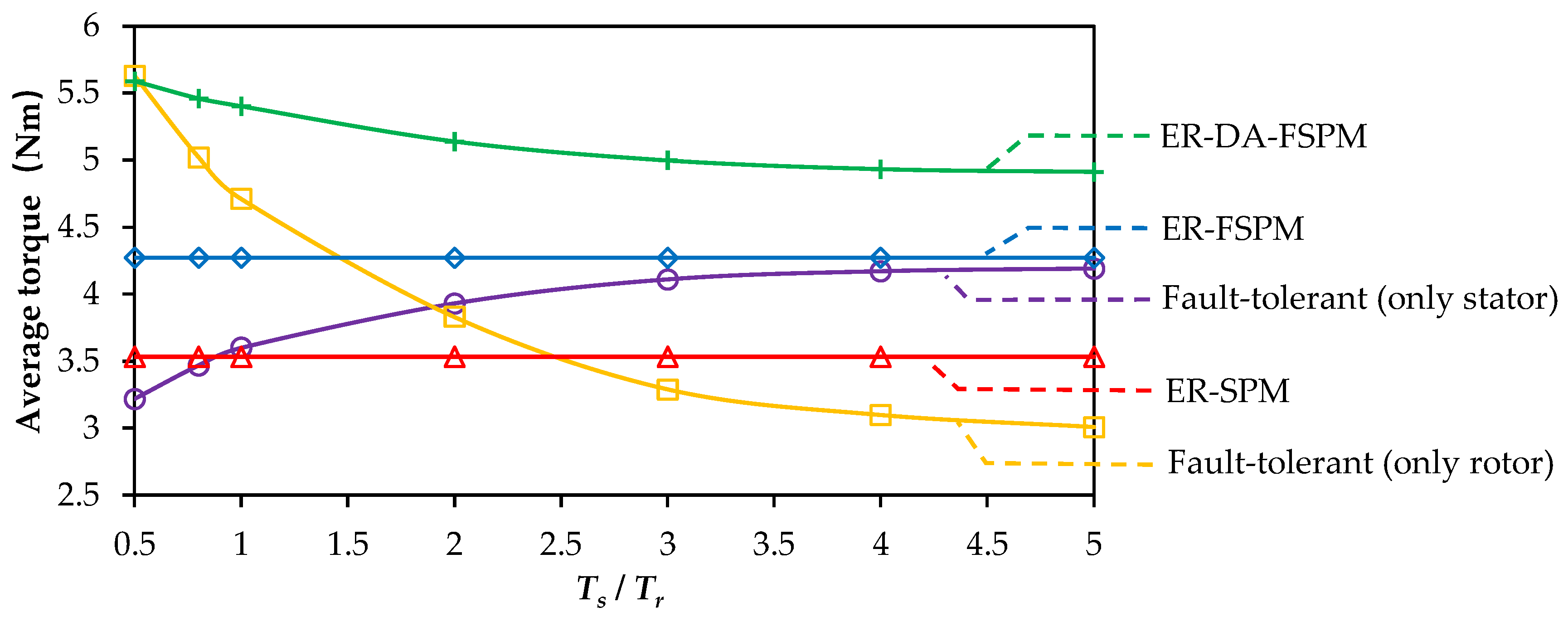
In order to make a fair comparison, the three types of machines are designed with the fixed parameter values shown in Table 6. Sequential optimization is also applied to maximize the average torque for ER-FSPM and ER-SPM machines. The averages of the three machines are shown in Figure 13. It can be found that when Ts/Tr ranges from 0.5 to 5, the least average torque of ER-DA-FSPM can still reach 4.91Nm. The average torques for ER-SPM and ER-FSPM machines are 3.55 Nm and 4.32 Nm, respectively. Therefore, the ER-DA-FSPM machine shows noticeably better torque capability than the ER-SPM and ER-FSPM machines.
Table 6.
Main design parameters of three machines.
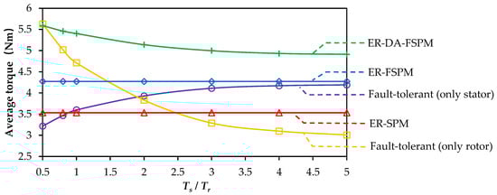
Figure 13.
Optimized average torque of different machines.
4.2. Comparison of Fault-Tolerant Capability for Different Machines
To guarantee machine reliability, the winding temperature is usually carefully checked within the insulation limit, even continuously operating at full load for a much longer time. Compared to the DA-ER-FSPM machine itself, the fault is more likely to happen in the power electronic devices of the converters. Therefore, in this paper, fault-tolerant capability refers to the output torque capability under the same copper loss when a fault occurs in the stator or rotor converter, and the corresponding winding set is completely unsupplied. In addition, the operation of the remaining winding set does not require complicated fault-tolerant control strategies. The average torque when only the stator or rotor winding operates is shown in Figure 13, which is also obtained under total copper loss 24 W. Considering that the failure possibility of the rotor winding is higher due to the existence of the slip ring, the stator torque should be specially focused. It can be found that, when Ts/Tr is 2, the stator winding can output a torque of 76.5% for the whole ER-DA-FSPM machine, which still exceeds that of the ER-SPM machine, and reaches about 92.0% for the ER-FSPM machine. When Ts/Tr becomes larger, the increasing rate of stator torque decreases due to magnetic saturation. In contrast, in the event of a stator-winding failure, both the ER-FSPM machine and the ER-SPM machine are unable to produce torque. Moreover, when Ts/Tr is 2, if the stator winding of the ER-DA-FSPM machine fails, the rotor winding can still generate an average torque of 74.5% for the whole ER-DA-FSPM machine. It is also larger than that of the ER-SPM machine, reaching 89.7% of the ER-FSPM machine under normal operation. Compared to the condition of Ts/Tr = 3, although the stator’s average torque is slightly smaller under fault-tolerant operations, the rotor’s average torque under fault-tolerant operation leads to more torque, and the total torque under normal operation is also larger. Therefore, Ts/Tr = 2 is recommended for the in-wheel machines to achieve decent torque and fault-tolerant capability.
5. Experimental Validation
5.1. Prototype Machine and Experimental Setup
In this section, experimental validation is performed to verify the FE analysis on a 3-stator-phase/5-rotor-phase and a 12-stator-slot/10-rotor-slot internal-rotor DA-FSPM machine. The prototype DA-FSPM machine is shown in Figure 14, and the parameters are listed in Table 7. Since the internal-rotor DA-FSPM machine has a similar working principle to ER-DA-FSPM machines, the experiments on the prototype machine can still validate the accuracy of FE simulation and theoretical analysis. The rotor windings are connected to the slip ring via the groove on the shaft. The experimental setup is shown in Figure 15. The prototype DA-FSPM machine is driven by a DSP controller, and the load is provided by the dynamometer.
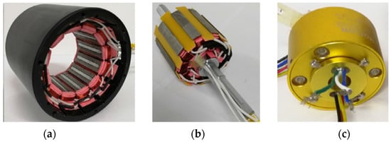
Figure 14.
Prototype DA-FSPM machine. (a) Stator. (b) Rotor. (c) Slip ring.
Table 7.
Parameters of prototype machine.
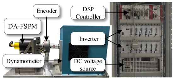
Figure 15.
Experimental setup.
5.2. Torque Experiments and Discussion
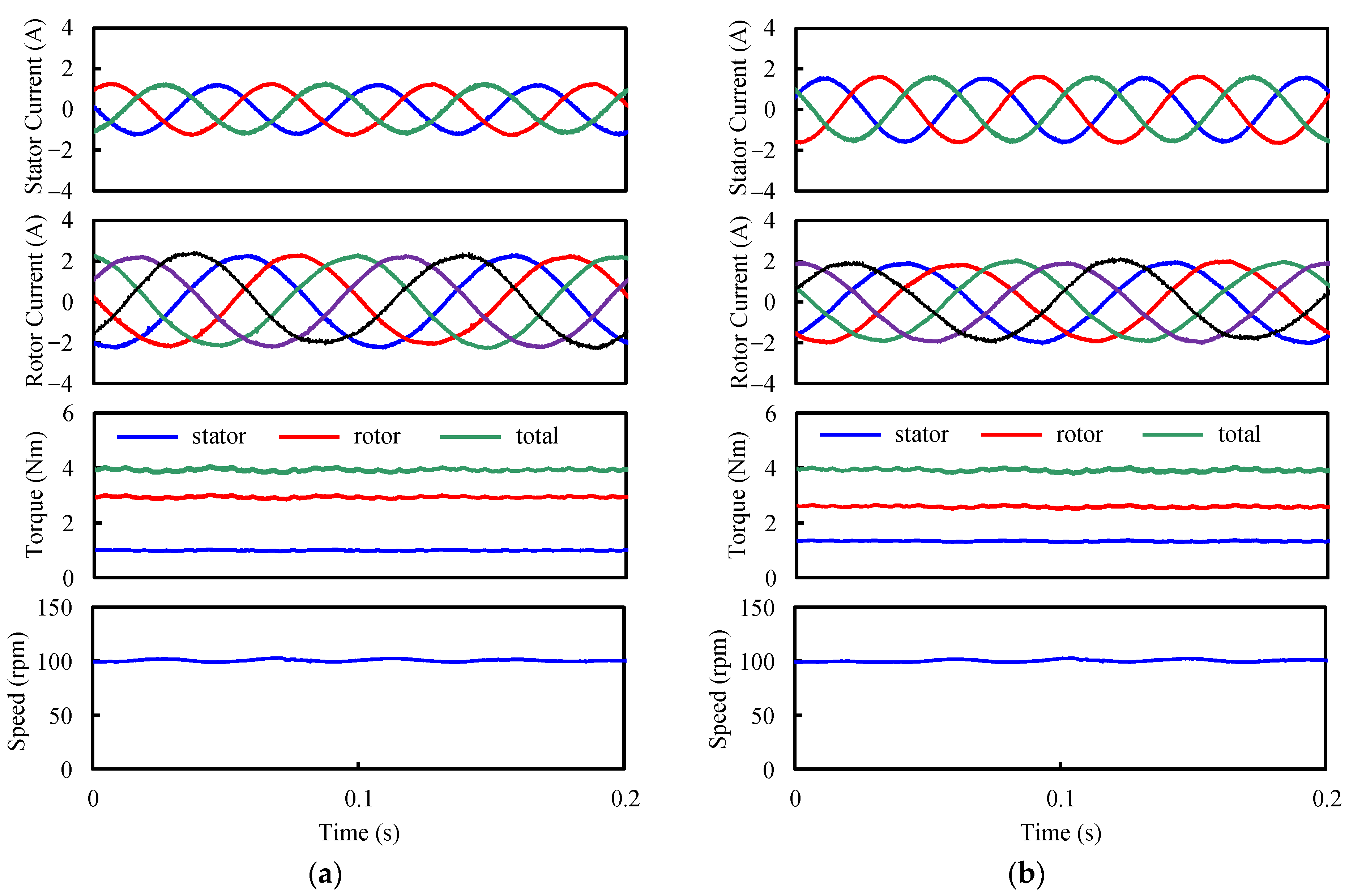
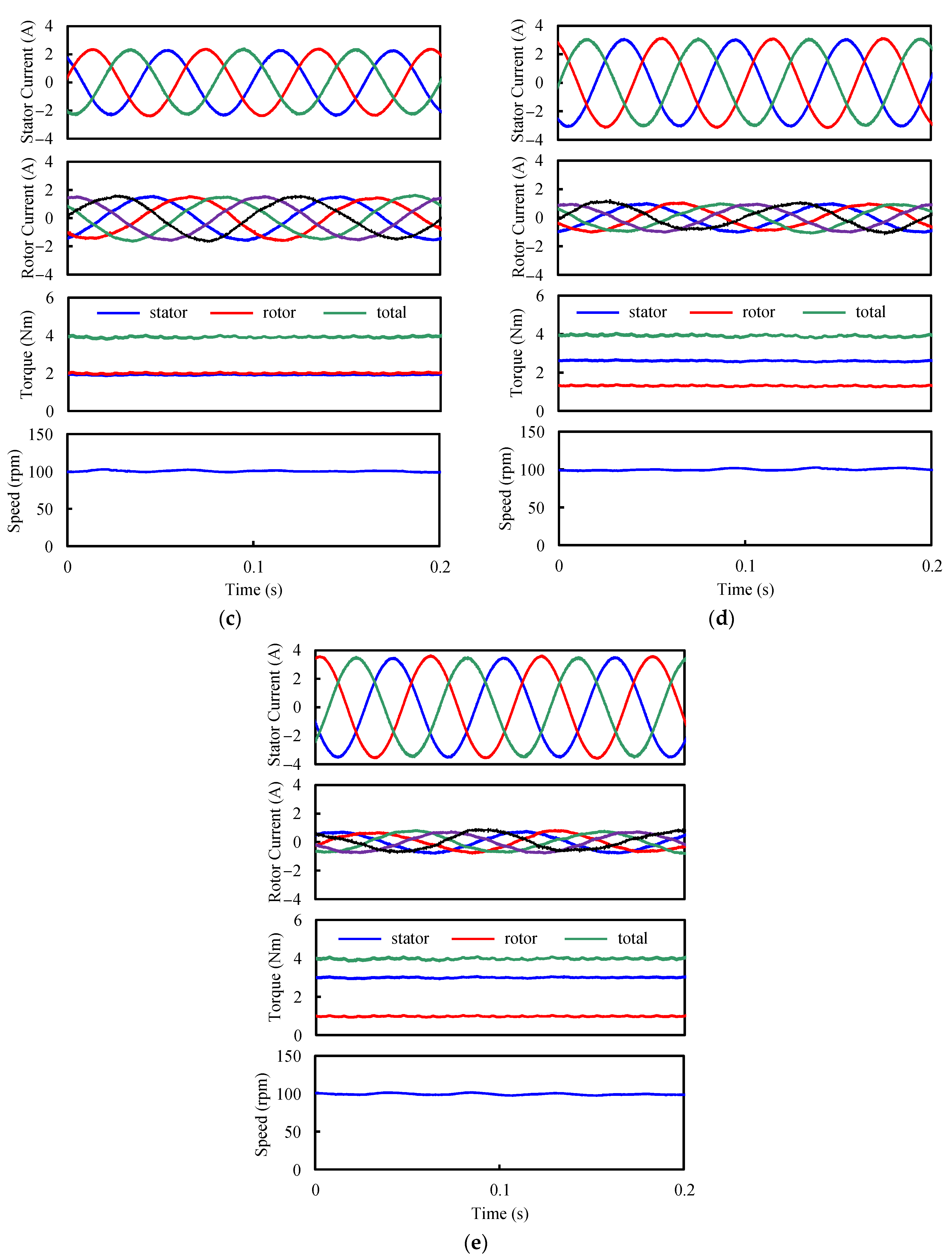
Since the DA-FSPM machine operates in the motor mode, the total torque is set as 4 Nm. The current, torque, and speed waveforms under different Ts/Tr are shown in Figure 16. It can be found that sinusoidal currents are input into the stator and rotor windings. Although there is a slight ripple in the torque waveforms, the average total torque is 4 Nm. The torque components generated by the stator and rotor windings change with the torque ratio. The rotor speed is 100 rpm with negligible ripples.
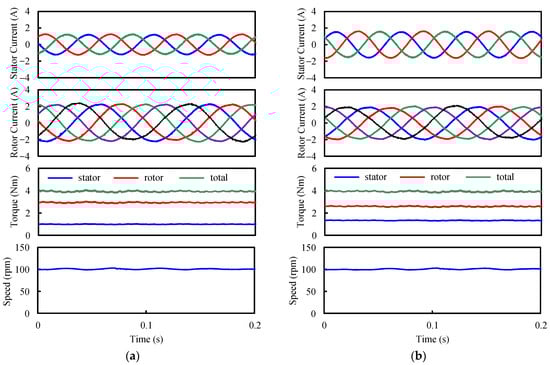
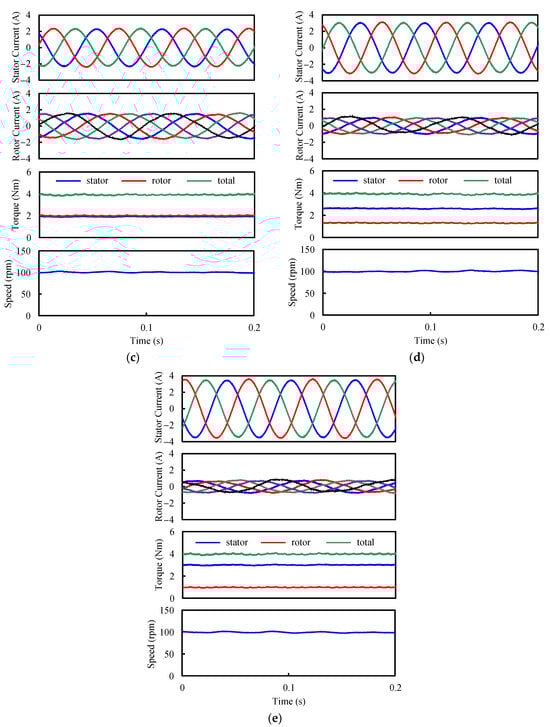
Figure 16.
Current, torque, and speed waveforms under different stator/rotor torque ratios. (a) Ts/Tr = 1/3. (b) Ts/Tr = 1/2. (c) Ts/Tr = 1. (d) Ts/Tr = 2. (e) Ts/Tr = 3.
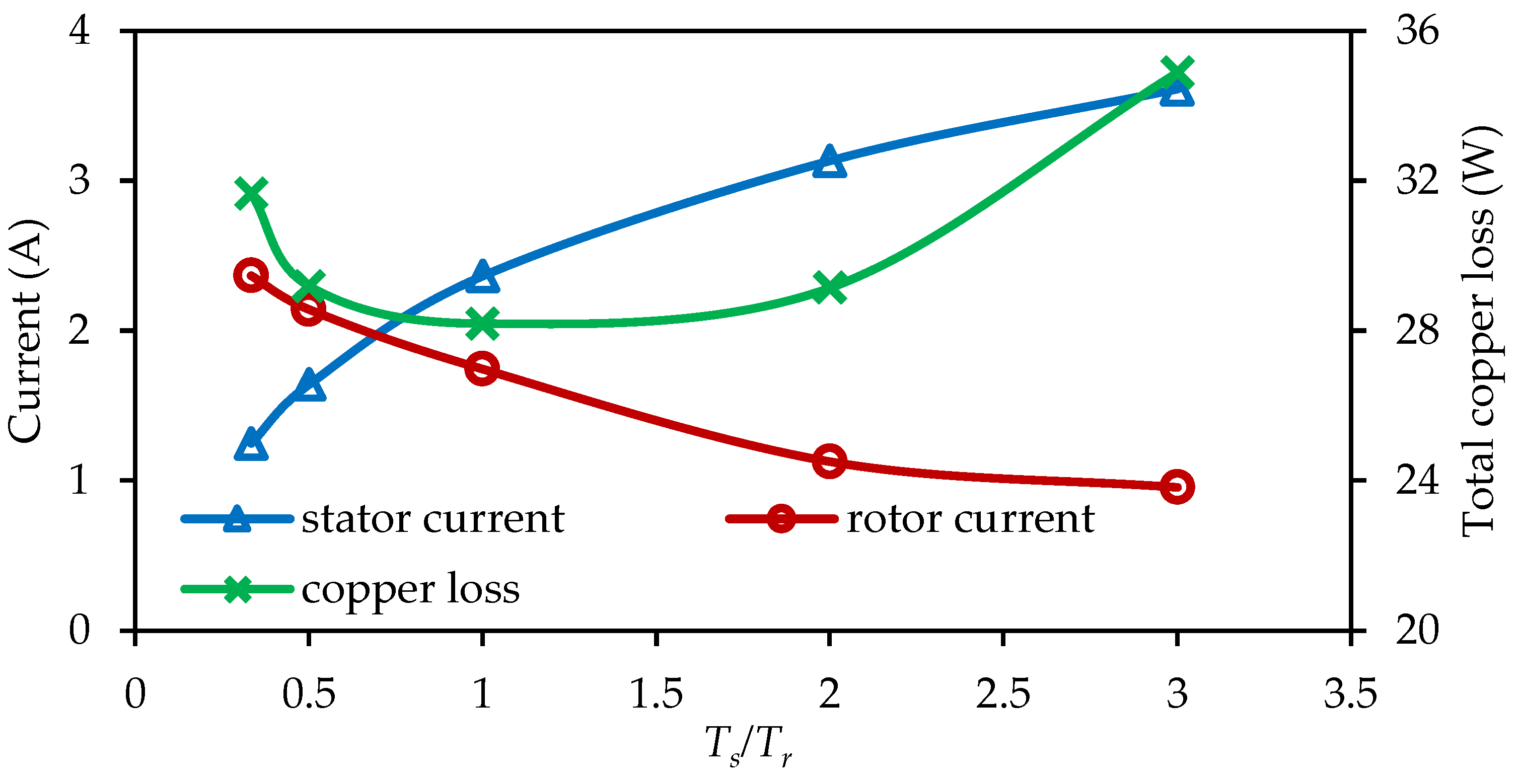
The stator and rotor current amplitude and the total copper loss are summarized in Figure 17. The total copper loss is calculated as
where Zs and Zr, Is and Ir, and Rs and Rr are the phase number, RMS phase current, and phase resistance of stator and rotor winding, respectively.
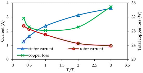
Figure 17.
Variation of current amplitude and total copper loss with Ts/Tr in the experiments.
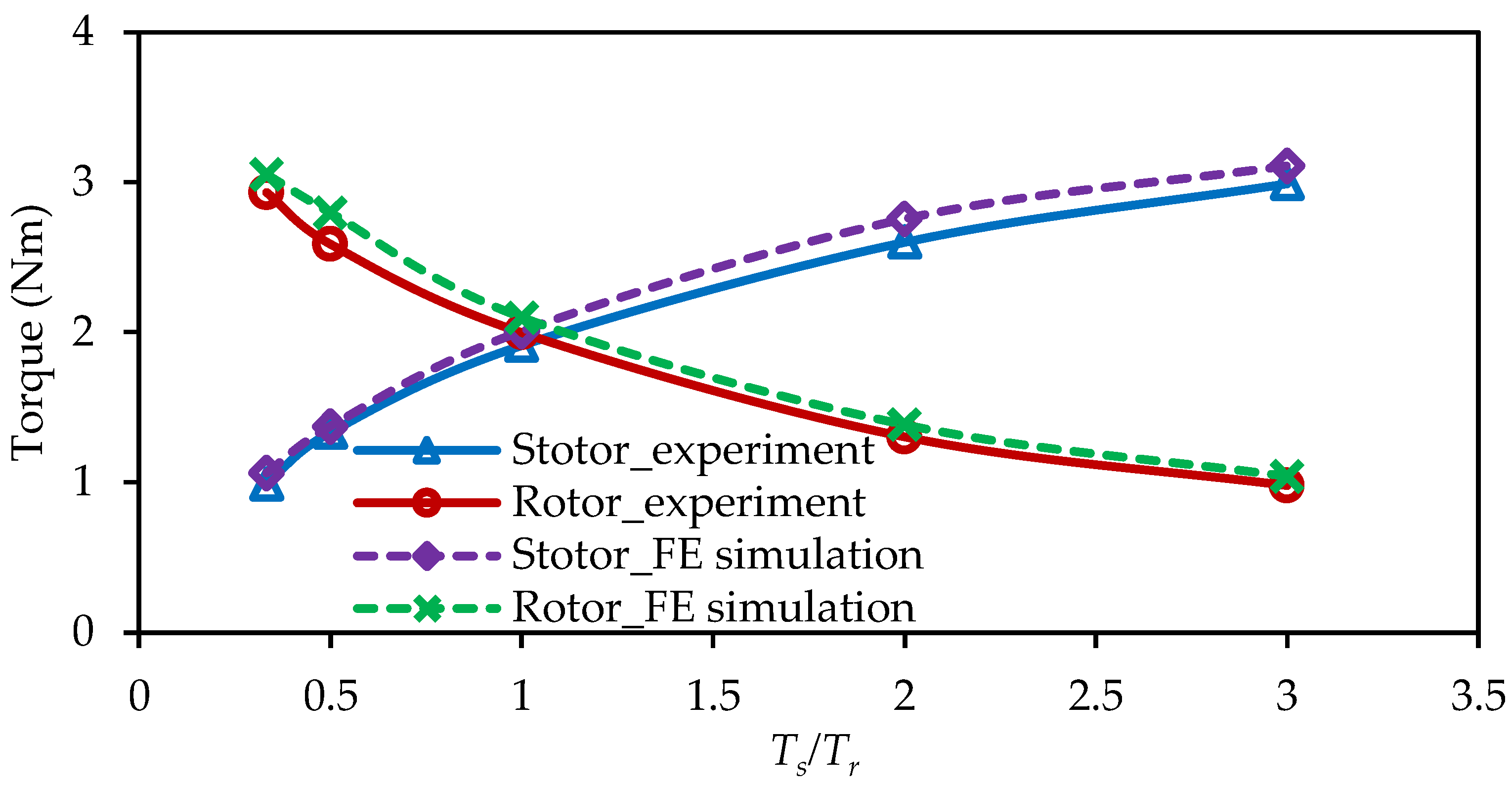
When the total torque remains fixed at 4 Nm, and when Ts/Tr increases, the stator-current amplitude increases, whereas the rotor-current amplitude decreases. In addition, the copper loss first decreases and then increases. When Ts/Tr < 1, the rotor’s winding generates a larger average torque. However, the rotor winding has a larger phase resistance and more phases. Thus, the copper loss decreases with the increasing Ts/Tr. When Ts/Tr > 1, the stator windings generate more torque components. However, since stator winding shows weaker torque capability than rotor winding, the increased rate of the stator current is larger than the decreasing rate of the rotor current. Therefore, the total copper increases with Ts/Tr. When the same currents are input in the FE simulation, the stator and rotor torque with Ts/Tr are shown in Figure 18. It can be found the measured torque is slightly smaller than the FE-predicted results due to the end effect. In addition, the variation trends are close to each other. Therefore, the effectiveness of FE simulation is confirmed, thereby validating the preceding theoretical analysis.
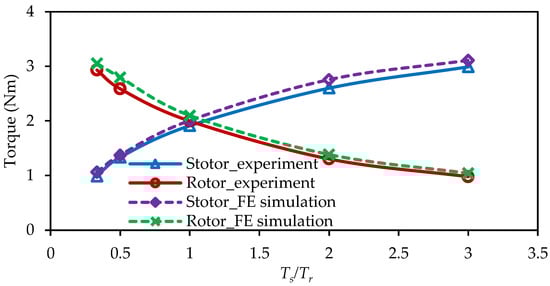
Figure 18.
Variation of average torque with Ts/Tr in the experiments and simulation.
5.3. Speed Experiments and Discussion
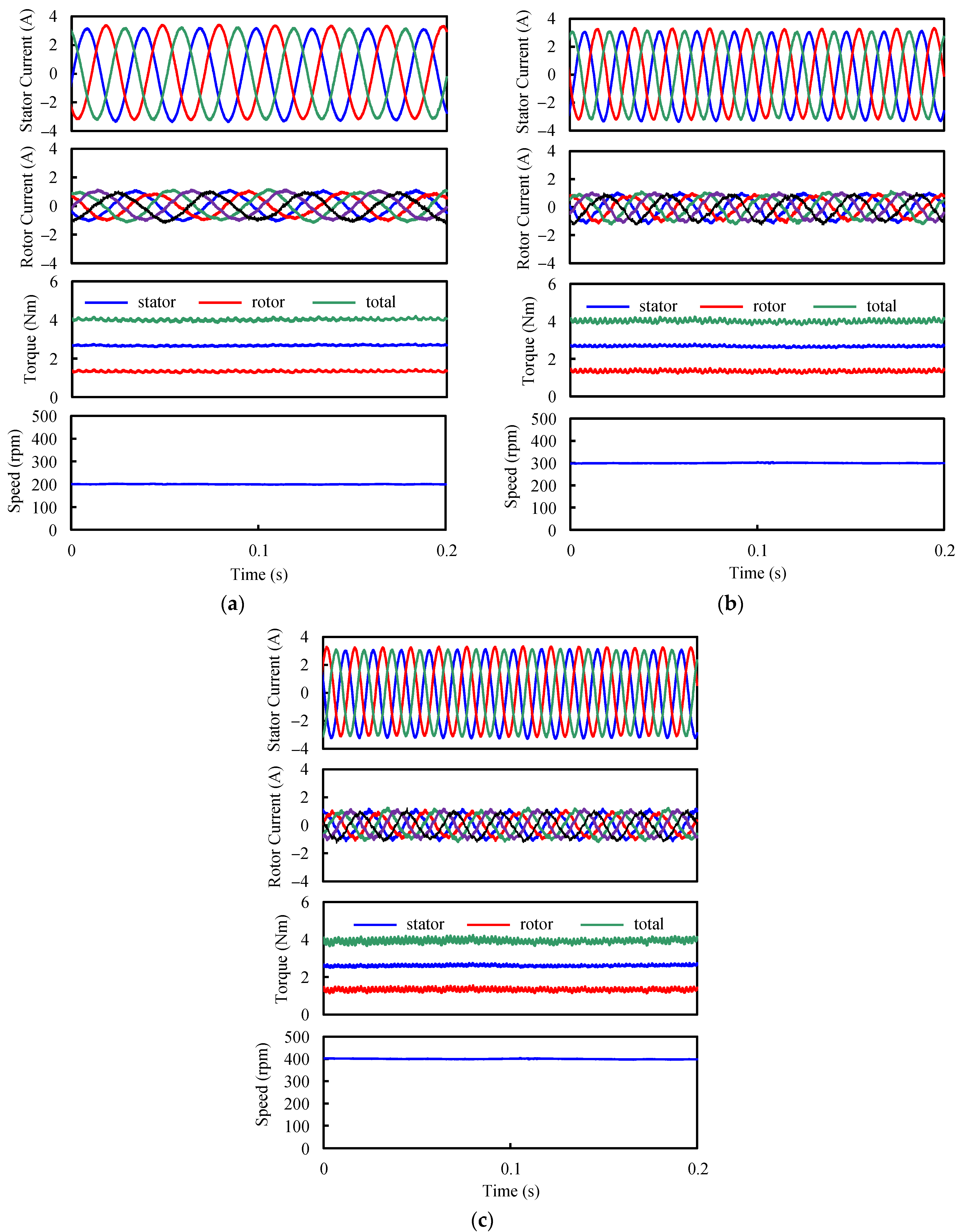
The current, torque, and speed waveforms under different rotor speeds when Ts/Tr = 2 are shown in Figure 19. Compared to the condition of the rotor speed being 100 rpm, which is shown in Figure 16d, it can be found that torque capability remains unchanged when rotor speed increases at the same total copper loss. Therefore, it can be concluded that the above theoretical results are still applicable when the machine operates at different rotor speeds.
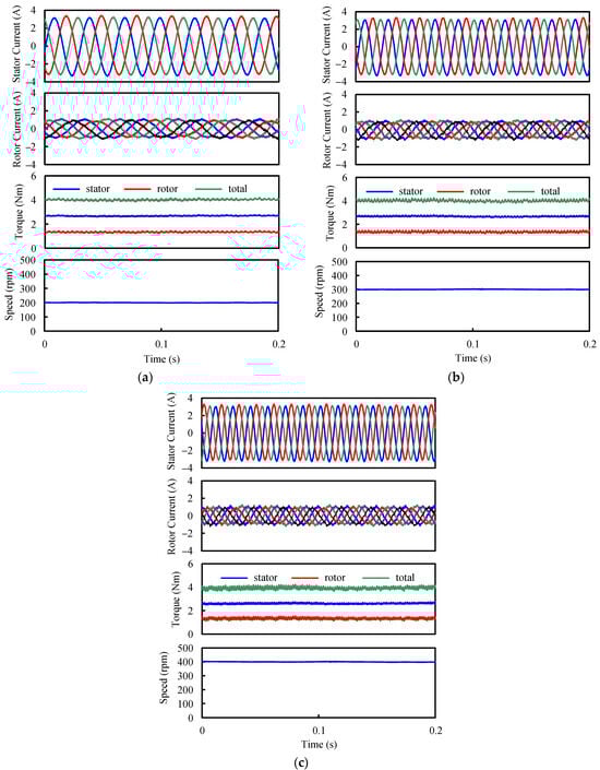
Figure 19.
Current, torque, and speed waveforms under different rotor speeds when Ts/Tr = 2. (a) 200 rpm. (b) 300 rpm. (c) 400 rpm.
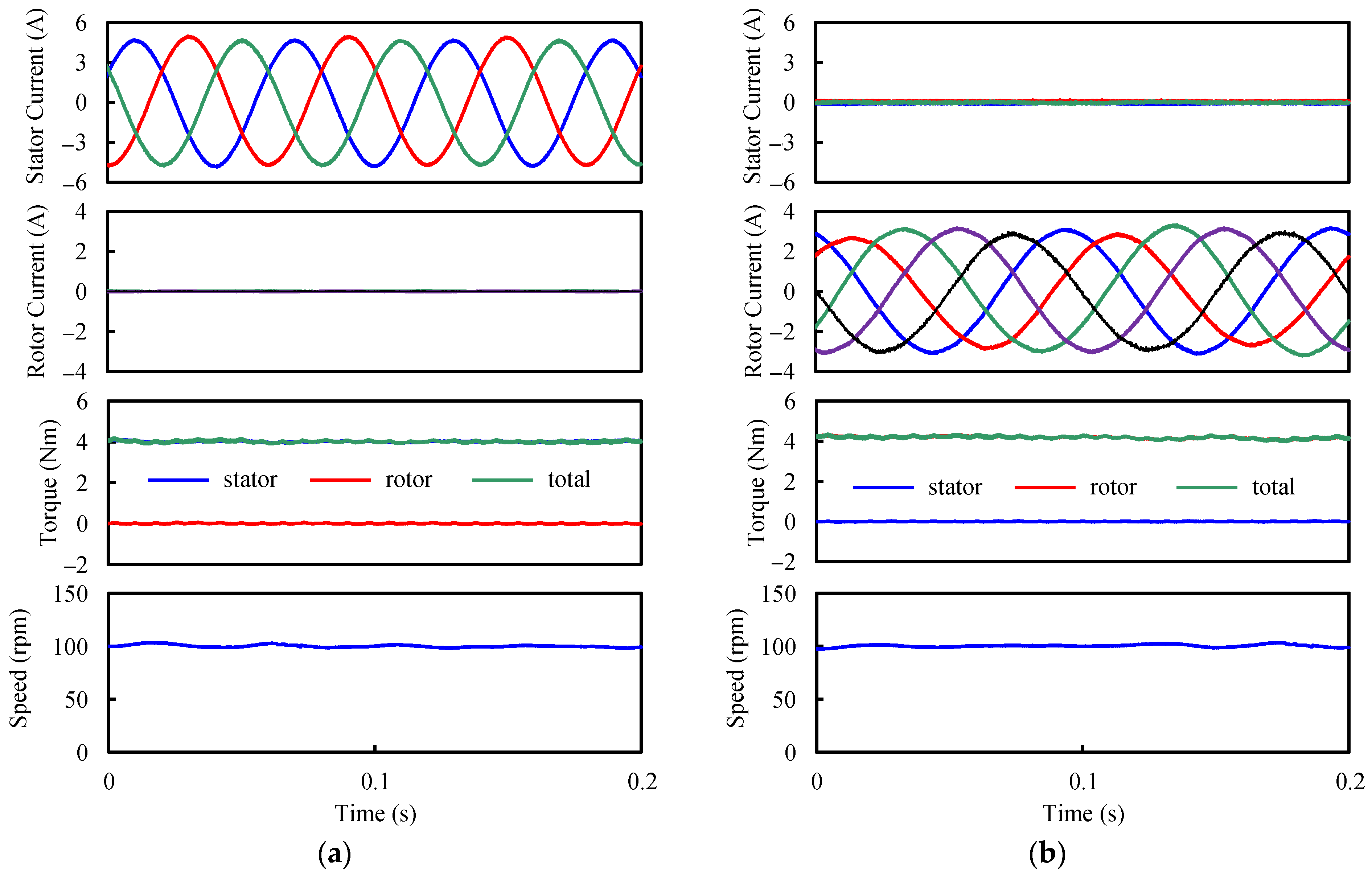
5.4. Fault-Tolerant Experiments and Discussion
The current, torque, and speed waveforms when only stator or rotor winding works are shown in Figure 20. When the total torque remains fixed, the copper losses for only stator- and rotor-fault-tolerant operation are 50.4 W and 58.1 W, respectively, which are much larger than those under normal conditions. In addition, when the current values are input into the FE simulation, the predicted average torques are 4.11 Nm and 4.08 Nm, which are close to the experimental results. Therefore, the accuracy of the FE simulation is again validated.
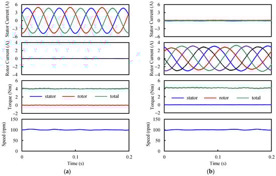
Figure 20.
Current, torque, and speed waveforms under fault-tolerant operation. (a) Only stator. (b) Only rotor.
6. Conclusions
The paper focuses on the influence of stator/rotor torque ratio on torque performance on ER-DA-FSPM machines. Firstly, the MMF-permeance model of the machine is established to analyze the dominant airgap field harmonics. Then, in order to investigate the influence of stator/rotor torque ratio, sequential optimization is used to obtain maximum average torques under different stator/rotor torque ratios. It is found that the optimized average torque decreases with increasing torque ratio. This trend is attributed to the reduction in the positive torque component generated by the sixth airgap field harmonics and the rise in the negative torque component produced by the eighth field harmonics. Additionally, the optimized dimensional values of split ratio and PM arcs should increase and decrease when the stator/rotor torque ratio increases, respectively. Furthermore, the paper conducts a comparison of ER-FSPM, ER-DA-FSPM, and ER-SPM machines. When the stator/rotor torque ratio is 2, the torque output of the ER-DA-FSPM machine can be 20.4% and 45.4% greater than the ER-SPM and ER-FSPM machines. Moreover, under rotor-armature failure, the stator winding can output torque 76.5% of that of the whole ER-DA-FSPM machine, which still exceeds that of the ER-SPM machine and reaches about 92.0% of that of the ER-FSPM machine. When the stator winding of the ER-DA-FSPM machine fails, the rotor winding can still generate an average torque of 74.5% of that of the whole ER-DA-FSPM machine, which is also larger than that of the ER-SPM machine and reaches 89.7% of that of the ER-FSPM machine under normal operation. These results strongly support that the ER-DA-FSPM machine has excellent torque density and fault-tolerant capability for in-wheel machine applications, where the stator winding is designed to produce larger torque output. Finally, the theoretical analysis is validated by experiments of torque, speed, and fault-tolerant capability.
Author Contributions
Methodology, Z.Z.; Software, Z.Z.; Validation, Y.D. and L.Y.; Formal analysis, Z.Z.; Investigation, Z.Z.; Resources, Y.D. and L.Y.; Data curation, Z.Z.; Writing—original draft, Z.Z.; Writing—review & editing, Z.Z., Y.D. and L.Y.; Visualization, Y.D.; Supervision, Y.D. and L.Y.; Project administration, Y.D. and L.Y.; Funding acquisition, Y.D. and L.Y. All authors have read and agreed to the published version of the manuscript.
Funding
This research was funded by Jiangsu Funding Program for Excellent Postdoctoral Talent, grant number 2023ZB259.
Data Availability Statement
Data are contained within the article.
Conflicts of Interest
The authors declare no conflict of interest.
References
- Zhao, X.; Doering, O.C.; Tyner, W.E. The Economic Competitiveness and Emissions of Battery Electric Vehicles in China. Appl. Energy 2015, 156, 666–675. [Google Scholar] [CrossRef]
- Rodrigues Teixeira, A.C.; Sodre, J.R. Impacts of Replacement of Engine Powered Vehicles by Electric Vehicles on Energy Consumption and CO2 Emissions. Transp. Res. Part D Transp. Environ. 2018, 59, 375–384. [Google Scholar] [CrossRef]
- Fu, S.; Fu, H. A Method to Predict Electric Vehicles’ Market Penetration as Well as Its Impact on Energy Saving and CO2 Mitigation. Sci. Prog. 2021, 104, 00368504211040286. [Google Scholar] [CrossRef] [PubMed]
- de Moraes, D.R.; Soares, L.O.; Guimaraes, V.d.A.; de Oliveira, K.F.; Hernandez-Callejo, L.; Ribeiro Vieira, G.M.; Mancebo Boloy, R.A. Energy-Ecological Efficiency of the Fuel Cell Electric Vehicle Powered by Different Biofuels. Clean Technol. Environ. Policy 2022, 24, 1389–1402. [Google Scholar] [CrossRef]
- Dadashnialehi, A.; Bab-Hadiashar, A.; Cao, Z.; Kapoor, A. Intelligent Sensorless ABS for In-Wheel Electric Vehicles. IEEE Trans. Ind. Electron. 2014, 61, 1957–1969. [Google Scholar] [CrossRef]
- Fan, Y.; Zhang, L.; Huang, J.; Han, X. Design, Analysis, and Sensorless Control of a Self-Decelerating Permanent-Magnet In-Wheel Motor. IEEE Trans. Ind. Electron. 2014, 61, 5788–5797. [Google Scholar] [CrossRef]
- Li, C.; Guo, X.; Fu, J.; Fu, W.; Liu, Y.; Chen, H.; Wang, R.; Li, Z. Design and Analysis of a Novel Double-Stator Double-Rotor Motor Drive System for In-Wheel Direct Drive of Electric Vehicles. Machines 2022, 10, 27. [Google Scholar] [CrossRef]
- Huang, J.; Liu, Y.; Liu, M.; Cao, M.; Yan, Q. Multi-Objective Optimization Control of Distributed Electric Drive Vehicles Based on Optimal Torque Distribution. IEEE Access 2019, 7, 16377–16394. [Google Scholar] [CrossRef]
- Wei, H.; Zhang, N.; Liang, J.; Ai, Q.; Zhao, W.; Huang, T.; Zhang, Y. Deep Reinforcement Learning Based Direct Torque Control Strategy for Distributed Drive Electric Vehicles Considering Active Safety and Energy Saving Performance. Energy 2022, 238, 121725. [Google Scholar] [CrossRef]
- Li, Y.; Huang, X.; Yu, D.; Zhang, K.; Zhang, J. Design and Analysis of a Outer-Rotor Permanent-Magnet Flux-Modulated Motor for Electric Vehicles. In Proceedings of the 2016 IEEE Conference on Electromagnetic Field Computation (CEFC), Miami, FL, USA, 13–16 November 2016; p. 1. [Google Scholar]
- Zhu, X.; Shu, Z.; Quan, L.; Xiang, Z.; Pan, X. Design and Multicondition Comparison of Two Outer-Rotor Flux-Switching Permanent-Magnet Motors for In-Wheel Traction Applications. IEEE Trans. Ind. Electron. 2017, 64, 6137–6148. [Google Scholar] [CrossRef]
- Bonthu, S.S.R.; Tarek, M.T.B.; Choi, S. Optimal Torque Ripple Reduction Technique for Outer Rotor Permanent Magnet Synchronous Reluctance Motors. IEEE Trans. Energy Convers. 2018, 33, 1184–1192. [Google Scholar] [CrossRef]
- Rauch, S.E.; Johnson, L.J. Design Principles of Flux-Switch Alternators [Includes Discussion]. Trans. Am. Inst. Electr. Eng. Part III Power Appar. Syst. 1955, 74, 1261–1268. [Google Scholar] [CrossRef]
- Chen, H.; EL-Refaie, A.M.; Demerdash, N.A.O. Flux-Switching Permanent Magnet Machines: A Review of Opportunities and Challenges-Part I: Fundamentals and Topologies. IEEE Trans. Energy Convers. 2020, 35, 684–698. [Google Scholar] [CrossRef]
- Chen, H.; EL-Refaie, A.M.; Demerdash, N.A.O. Flux-Switching Permanent Magnet Machines: A Review of Opportunities and Challenges-Part II: Design Aspects, Control, and Emerging Trends. IEEE Trans. Energy Convers. 2020, 35, 699–713. [Google Scholar] [CrossRef]
- Fei, W.; Luk, P.C.K.; Shen, J.X.; Wang, Y.; Jin, M. A Novel Permanent-Magnet Flux Switching Machine with an Outer-Rotor Configuration for In-Wheel Light Traction Applications. IEEE Trans. Ind. Appl. 2012, 48, 1496–1506. [Google Scholar] [CrossRef]
- Fei, W.; Luk, P.C.K.; Miao, D.-M.; Shen, J.-X. Investigation of Torque Characteristics in a Novel Permanent Magnet Flux Switching Machine with an Outer-Rotor Configuration. IEEE Trans. Magn. 2014, 50, 1–10. [Google Scholar] [CrossRef]
- Chen, J.T.; Zhu, Z.Q.; Iwasaki, S.; Deodhar, R.P. Influence of Slot Opening on Optimal Stator and Rotor Pole Combination and Electromagnetic Performance of Switched-Flux PM Brushless AC Machines. IEEE Trans. Ind. Appl. 2011, 47, 1681–1691. [Google Scholar] [CrossRef]
- Chen, J.T.; Zhu, Z.Q.; Iwasaki, S.; Deodhar, R.P. A Novel Hybrid-Excited Switched-Flux Brushless AC Machine for EV/HEV Applications. IEEE Trans. Veh. Technol. 2011, 60, 1365–1373. [Google Scholar] [CrossRef]
- Zhu, Z.Q.; Chen, J.I.; Pang, Y.; Howe, D.; Iwasaki, S.; Deodhar, R. Analysis of a Novel Multi-Tooth Flux-Switching PM Brushless AC Machine for High Torque Direct-Drive Applications. IEEE Trans. Magn. 2008, 44, 4313–4316. [Google Scholar] [CrossRef]
- Zhou, Y.J.; Zhu, Z.Q. Torque Density and Magnet Usage Efficiency Enhancement of Sandwiched Switched Flux Permanent Magnet Machines Using V-Shaped Magnets. IEEE Trans. Magn. 2013, 49, 3834–3837. [Google Scholar] [CrossRef]
- Hua, W.; Zhang, H.; Cheng, M.; Meng, J.; Hou, C. An Outer-Rotor Flux-Switching Permanent-Magnet-Machine with Wedge-Shaped Magnets for In-Wheel Light Traction. IEEE Trans. Ind. Electron. 2017, 64, 69–80. [Google Scholar] [CrossRef]
- Jin, M.-J.; Wang, C.-F.; Shen, J.-X.; Xia, B. A Modular Permanent-Magnet Flux-Switching Linear Machine with Fault-Tolerant Capability. IEEE Trans. Magn. 2009, 45, 3179–3186. [Google Scholar] [CrossRef]
- Taras, P.; Li, G.-J.; Zhu, Z.Q. Comparative Study of Fault-Tolerant Switched-Flux Permanent-Magnet Machines. IEEE Trans. Ind. Electron. 2017, 64, 1939–1948. [Google Scholar] [CrossRef]
- Shao, L.; Hua, W.; Zhu, Z.Q.; Tong, M.; Zhao, G.; Yin, F.; Wu, Z.; Cheng, M. Investigation of Torque Characteristics in a Novel Permanent Magnet Flux Switching Machine with an Outer-Rotor Con-Figuration. IEEE Trans. Ind. Appl. 2017, 53, 3305–3316. [Google Scholar] [CrossRef]
- Zong, Z.; Quan, L.; Xiang, Z. Comparison of Double-Stator Flux-Switching Permanent Magnet Machine and Double-Stator Permanent Magnet Synchronous Machine for Electric Vehicle Applications. In Proceedings of the 2014 17th International Conference on Electrical Machines and Systems (ICEMS), Hangzhou, China, 22–25 October 2014; pp. 234–239. [Google Scholar]
- Kim, D.; Hwang, H.; Bae, S.; Lee, C. Analysis and Design of a Double-Stator Flux-Switching Permanent Magnet Machine Using Ferrite Magnet in Hybrid Electric Vehicles. IEEE Trans. Magn. 2016, 52, 8106604. [Google Scholar] [CrossRef]
- Kana Padinharu, D.K.; Li, G.J.; Zhu, Z.Q.; Azar, Z.; Clark, R.; Thomas, A. Effect of Airgap Length on Electromagnetic Performance of Surface Mounted Permanent Magnet Vemier Machine. In Proceedings of the 2020 International Conference on Electrical Machines (ICEM), Gothenburg, Sweden, 23 August 2020; pp. 1882–1888. [Google Scholar]
- Wu, L.; Zhu, J.; Fang, Y. A Novel Doubly-Fed Flux-Switching Permanent Magnet Machine with Armature Windings Wound on Both Stator Poles and Rotor Teeth. IEEE Trans. Ind. Electron. 2020, 67, 10223–10232. [Google Scholar] [CrossRef]
- Zhu, J.; Wu, L.; Wen, H. Optimization and Comparison of Dual-Armature Flux-Switching Permanent Magnet Machines with Different Stator Core Shapes. IEEE Trans. Ind. Appl. 2022, 58, 314–324. [Google Scholar] [CrossRef]
- Zhang, G.; Hua, W.; Cheng, M.; Liao, J.; Wang, K.; Zhang, J. Investigation of an Improved Hybrid-Excitation Flux-Switching Brushless Machine for HEV/EV Applications. IEEE Trans. Ind. Appl. 2015, 51, 3791–3799. [Google Scholar] [CrossRef]
- Lin, T.C.; Zhu, Z.Q.; Liu, K.; Liu, J.M. Improved Sensorless Control of Switched-Flux Permanent-Magnet Synchronous Machines Based on Different Winding Configurations. IEEE Trans. Ind. Electron. 2016, 63, 123–132. [Google Scholar] [CrossRef]
- Shu, Z.; Zhu, X.; Quan, L.; Du, Y.; Liu, C. Electromagnetic Performance Evaluation of an Outer-Rotor Flux-Switching Permanent Magnet Motor Based on Electrical-Thermal Two-Way Coupling Method. Energies 2017, 10, 677. [Google Scholar] [CrossRef]
- Tovar-Barranco, A.; Lopez-de-Heredia, A.; Villar, I.; Briz, F. Modeling of End-Space Convection Heat-Transfer for Internal and External Rotor PMSMs with Fractional-Slot Concentrated Windings. IEEE Trans. Ind. Electron. 2021, 68, 1928–1937. [Google Scholar] [CrossRef]
- Feng, T.; Shu, L. Game-Based Multiobjective Optimization of Suspension System for In-Wheel Motor Drive Electric Vehicle. Math. Probl. Eng. 2021, 2021, 5589199. [Google Scholar] [CrossRef]
- Awah, C.C.; Zhu, Z.Q.; Wu, Z.Z.; Shi, J.T.; Wu, D. Comparison of Partitioned Stator Switched Flux Permanent Magnet Machines Having Single- and Double-Layer Windings. In Proceedings of the 2015 Tenth International Conference on Ecological Vehicles and Renewable Energies (EVER), Monte Carlo, Monaco, 31 March–2 April 2015; pp. 1–5. [Google Scholar]
- Li, G.; Ojeda, J.; Hoang, E.; Gabsi, M. Double and Single Layers Flux-Switching Permanent Magnet Motors: Fault Tolerant Model for Critical Applications. In Proceedings of the 2011 International Conference on Electrical Machines and Systems, Beijing, China, 20–23 August 2011; pp. 1–6. [Google Scholar]
- Chen, J.T.; Zhu, Z.Q. Comparison of All- and Alternate-Poles-Wound Flux-Switching PM Machines Having Different Stator and Rotor Pole Numbers. IEEE Trans. Ind. Appl. 2010, 46, 1406–1415. [Google Scholar] [CrossRef]
- Owen, R.L.; Zhu, Z.Q.; Thomas, A.S.; Jewell, G.W.; Howe, D. Alternate Poles Wound Flux-Switching Permanent-Magnet Brushless AC Machines. IEEE Trans. Ind. Appl. 2010, 46, 790–797. [Google Scholar] [CrossRef]
- Zheng, Y.; Wu, L.; Li, H.; Wen, H.; Qiu, L. Harmonic Analysis of Airgap Magnetic Fields in Doubly-Fed Flux Reversal Permanent Magnet Machines. IEEE Access 2020, 8, 134856–134867. [Google Scholar] [CrossRef]
- Zhang, L.; Wu, L.; Wen, H.; Niu, F.; Lu, Q. Improved Primary/Secondary Pole Number Combinations for Dual-Armature Linear Switched Flux Permanent Magnet Machines. IEEE Trans. Transp. Electrif. 2021, 7, 2589–2599. [Google Scholar] [CrossRef]
- Wu, Z.Z.; Zhu, Z.Q. Analysis of Air-Gap Field Modulation and Magnetic Gearing Effects in Switched Flux Permanent Magnet Machines. IEEE Trans. Magn. 2015, 51, 8105012. [Google Scholar] [CrossRef]
- Zhu, Z.Q.; Liu, Y. Analysis of Air-Gap Field Modulation and Magnetic Gearing Effect in Fractional-Slot Concentrated-Winding Permanent-Magnet Synchronous Machines. IEEE Trans. Ind. Electron. 2018, 65, 3688–3698. [Google Scholar] [CrossRef]
- Huang, L.; Feng, J.; Guo, S.; Shi, J.; Zhu, Z.Q. Analysis of Power Factor in Variable Flux Reluctance Machines with MMF-Permeance Model. IET Electr. Power Appl. 2019, 13, 614–624. [Google Scholar] [CrossRef]
- Zhu, X.; Hua, W.; Wu, Z.; Huang, W.; Zhang, H.; Cheng, M. Analytical Approach for Cogging Torque Reduction in Flux-Switching Permanent Magnet Machines Based on Magnetomotive Force-Permeance Model. IEEE Trans. Ind. Electron. 2018, 65, 1965–1979. [Google Scholar] [CrossRef]
- Chen, H.; Li, D.; Qu, R.; Zou, T. Torque Capacity Improvement of Flux-Switching PM Machines Based on Directional Stator Permeance Design. IEEE Trans. Ind. Electron. 2024, 71, 4551–4561. [Google Scholar] [CrossRef]
- Pang, Y.; Zhu, Z.Q.; Howe, D. Analytical Determination of Optimal Split Ratio for Permanent Magnet Brushless Motors. IEE Proc.-Electr. POWER Appl. 2006, 153, 7–13. [Google Scholar] [CrossRef]


Disclaimer/Publisher’s Note: The statements, opinions and data contained in all publications are solely those of the individual author(s) and contributor(s) and not of MDPI and/or the editor(s). MDPI and/or the editor(s) disclaim responsibility for any injury to people or property resulting from any ideas, methods, instructions or products referred to in the content. |
© 2024 by the authors. Licensee MDPI, Basel, Switzerland. This article is an open access article distributed under the terms and conditions of the Creative Commons Attribution (CC BY) license (https://creativecommons.org/licenses/by/4.0/).