1. Introduction
Desertification causes the species and quantity of organisms in the ecosystem to decrease greatly, while biodiversity is destroyed, the land gradually becomes barren, and vegetation is gradually degraded or disappeared [
1,
2]. The decrease in vegetation increases the land exposure to the sun, resulting in a large amount of heat being absorbed by the land, thus affecting the climate and aggravating the phenomenon of drought and high temperature [
3,
4]. In addition, desertification gradually reduces the water content of the land and the groundwater is exhausted. Serious desertification will lead to the depletion of groundwater resources, resulting in serious water shortage. Desertification has a greater impact on agriculture and livestock, as it causes the loss of the land productive value and threatens the livelihoods of farmers and herders. According to statistics, desertification affects one fifth of the world’s population and one third of its land area, resulting in an annual global economic loss of USD 42.3 billion [
5,
6].
Controlling methodology for desertification is a hot topic. Dang, Xugang et al. [
7] stated that the soil structure can be improved by chemical sand fixation agents to achieve the purpose of desert control. The use of chemical sand fixation agents is simple and the effect is immediate, but the cost is high, and they may cause pollution to the local environment and have adverse effects on the ecosystem. Anderson [
8] proposed that desert land can be controlled by wind-driven sand transport. The advantage of wind-driven sand transport is that it can use the natural settlement of obstacles to fix sand and dust, and it has good economy and operability. However, sand control is limited to special areas or parts, and it will consume a lot of manpower and material resources for wind-driven sand transport, which is difficult to guarantee long-term results. Xie, Yunhu et al. [
9] reported that desertification can be controlled through mechanical sand barriers, which have the advantages of high flexibility, good stability, and easy maintenance, but also have the disadvantages of high construction cost and low efficiency.
In the controlling methodologies, paving straw checkerboard barriers is an effective method [
10,
11,
12]. Straw checkerboard barriers are a sand fixation technology that uses grass roots to resist wind [
13], control soil erosion, and conserve water, as shown in
Figure 1. The straw checkerboard barriers are built with straw, which is inserted 0.15–0.2 m deep so that it protrudes out of the dune surface by about 0.1–0.15 m, increasing surface roughness and reducing wind erosion, and these straw checkerboard barriers remain intact for 4–5 years. Due to the limited rainfall in desert areas, cultivated xerophytes placed in the straw checkerboard barriers have time to grow. Ten kinds of xerophytes were selected and planted in 1 m
2 straw checkerboard barriers. Four to five years after the restoration, the stability of the ecosystem on the surface of the dune was enhanced [
14], which slowed down the further expansion of the desert, promoted the recovery of vegetation [
15], provided favorable conditions for the survival of local plants and animals, accelerated the physical skin and evolution of the desert soil [
16,
17], and completed the feat of windbreak and sand fixation. Therefore, paving straw checkerboard barriers is an important means to control desertification.
At present, the straw checkerboard sand barriers are mainly paved manually, which has high labor intensity, low efficiency, and high cost. The automatic paving of straw checkerboard barriers overcomes the shortcomings of artificial planting, and effectively improves the paving efficiency and reduces the cost. In the design of this paper, the design methods of many scholars are referred to. For example, Lu Peng et al. [
18,
19] designed the Tree-Planting Vehicle and Intelligent Vehicle for Transportation in Greenhouses. In the process, it adopts the demand-function method to define the product function according to the design requirements for conceptual design. Huiping Guo et al. [
20,
21] carried out kinematics analysis to research three-dimensional modeling. The computational analysis method and finite element simulation method were adopted by Yingjie Yu et al. [
22,
23,
24,
25,
26]. It is worth mentioning that Suibing Li et al. [
27] combined the Seeding mechanism and clean energy when designing Seeding Robots, which further inspired the design of the portable paving vehicle for straw checkerboard sand barriers. The portable paving vehicle for straw checkerboard sand barriers designed in this paper integrates the design methods mentioned above. In the design process, the concept design of the portable paving vehicle for straw checkerboard sand barriers is carried out through the demand-function method. After that, the three-dimensional modeling of the portable paving vehicle for straw checkerboard sand barriers is carried out through SolidWorks, and the key components are calculated and analyzed. The motion of the grass insertion mechanism is simulated with multi-body kinematics, and the physical prototype is made to verify the performance of the portable paving vehicle for straw checkerboard sand barriers. The integration of various design methods ensures the rigor and feasibility of the design, which makes the design method in this paper superior to other design methods.
2. Design of the Portable Paving Vehicle for Straw Checkerboard Barriers
2.1. The Design Idea of the Portable Paving Vehicle for Straw Checkerboard Barriers
With the continuous progress of desertification control, straw checkerboard barrier paving is becoming more and more common, but manual straw checkerboard barrier paving is time consuming and laborious, and the demand for straw checkerboard barrier paving machines is increasing. The portable paving vehicle for straw checkerboard barriers proposed in this paper can realize the automatic planting of straw checkerboard barriers and reduce the labor cost. Therefore, in order to meet the actual needs, the design requirements of the portable paving vehicle for straw checkerboard barriers are detailed below.
The portable paving vehicle for straw checkerboard barriers is intended to use a single gear transmission to drive the rotation of the grass blade and the belt wheel at the same time, so as to achieve automatic grass insertion while moving.
The design of each part is linked, and the power source is single. The portable paving vehicle for straw checkerboard barriers only needs one power source to realize the function of the whole device. By connecting each part of the portable paving vehicle for straw checkerboard barriers with the transmission mechanism, all the parts are driven by one power source.
The chain plate replaces the wheel to strengthen the straw root. The portable paving vehicle for straw checkerboard barriers is designed to reinforce the straw checkerboard barriers during the completion of grass planting by installing a chain plate on the track to promote the root of the straw.
A security protection mechanism is designed to prevent damage. By installing a cellular mechanism in the portable paving vehicle for straw checkerboard barriers, it ensures that the equipment will automatically raise and tilt upward at a certain angle when the grass is obstructed, which can prevent the damage of the grass blade and improve the service life.
As shown in
Figure 2, the portable paving vehicle for straw checkerboard barriers has a frame and a wheeled track. The frame is provided with a feeding mechanism, a linkage mechanism, and a grass insertion mechanism. The feed mechanism consists of a storage hopper, a feed plate, and a vibration motor for shaking the straw checkerboard barriers to the ground. The linkage mechanism includes a driving part, a gear group, and a connecting rod group, and the power of the driving part is transferred to the wheeled track and the connecting rod group in an alternate form. The grass insertion mechanism is equipped with a grass insert blade to receive the power transmitted by the connecting rod group for grass insert operation. In order to work more effectively, the feeding mechanism is arranged in front of the frame, the storage hopper and the feeding plate are opposed to each other, and the vibration motor is located on the bottom of the feeding plate. The mower is arranged at the rear of the frame, and the mower blade and the frame are configured as a cellular mechanism to implement overload protection. The walking mechanism is configured as a track vehicle, and the first driven gear is configured on one of the wheel shafts.
2.2. The Process of Design
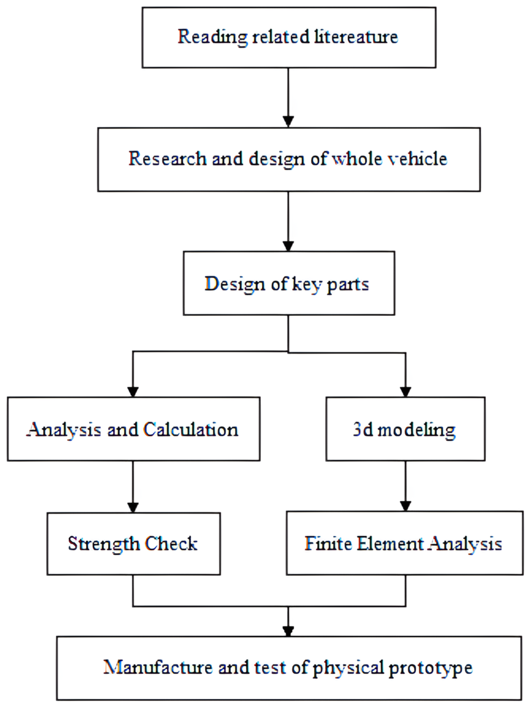
In order to improve the automation of the grass insertion process, the portable paving vehicle for straw checkerboard barriers is designed as a vehicle to control the desert by inserting straw checkerboard barriers. The insertion of straw checkerboard barriers is realized by the grass insertion mechanism and other useful structures and parts. Therefore, the design process becomes very important to enable the portable paving vehicle for straw checkerboard barriers to pave straw checkerboard barriers normally in the desert. The design process of the portable paving vehicle for straw checkerboard barriers includes the whole vehicle structure design [
28], key parts design [
29], and finite element analysis [
30]. In this paper, the method of 3D modeling will be used for design, the method of theoretical analysis and finite element analysis will be verified, and the experimental test will be evaluated. First of all, the related literature were read [
18,
31,
32], and the structure and key parts of the vehicle were designed through SolidWorks. Secondly, DynoWare was used to carry out a load test on the model of the grass insertion mechanism, and theoretical analysis was carried out through the test results to verify the rationality of the design scheme. Then, the finite element analysis of the mower mechanism and key parts was carried out by ABAQUS to further verify the rationality of the test scheme. Finally, a physical prototype was manufactured and the grass insertion experiment was carried out, and the design results were evaluated. The process of design is shown in
Figure 3.
2.3. Design of the Frame Structure
According to the above design ideas, the total length of the frame is 1120 mm, the total width of the frame is 600 mm, the total height is 543 mm, the motion range of the grass blade is 141.65 mm, the total length of the track car is 540 mm, and the distance between the two front and rear wheels is 320 mm. Among them, the distance between the right wheel and the grass blade is 183.5 mm, and the total height is 600 mm. The forward distance of the operation vehicle is 219 mm each time, which is conducive to the completion of small-scale automatic grass insertion requirements. As the portable paving vehicle for straw checkerboard barriers uses a single power source, it is equipped with a 34 w high-power motor. In order to ensure that the chain plate can effectively strengthen the straw root after grass insertion, the distance of each blade insertion is 220 mm. In order to ensure the normal operation of the safety protection mechanism, the motion range of the grass blade is 141.65 mm, so that the equipment can be automatically raised. The main technical parameters of the portable paving vehicle for straw checkerboard barriers are shown in
Table 1.
The concept diagram shown in
Figure 2 provides a visual representation of the proposed portable paving vehicle for straw checkerboard barriers. This illustration illustrates the overall structure and key components of a fully automated grass generation vehicle, providing an overview of its design and functionality. Advanced software tools such as SolidWorks 2020 and ABAQUS 2020 are utilized to enable further precise design and finite element analysis of the proposed mechanism.
2.4. Design of Mechanism
2.4.1. Design of Grass Insertion Mechanism
The transfer motion is transformed into a linear reciprocating motion with the characteristics of quick return, so as to drive the up and down movement of the blade, and realize the high-efficiency motion of grass insertion. In the double-side crank rocker mechanism, the constant speed rotation of the crank is transformed into the variable speed round-trip swing of the rocker with the crank as the primary moving part. In the sine mechanism, when the rocker rod swings, the driven rod moves reciprocally, and its speed changes according to the sine law. The grass insertion mechanism is shown as
Figure 4.
At rest, the distance between the blade and the ground is 42.33 mm. As shown in
Figure 5, the CAD calculation shows that the connecting rod can drive the grass insert blade to move up and down in the scope of 141.65 mm. Therefore, the depth of the grass insert blade is 99.32 mm, which is 141.65 mm minus 42.33 mm.
2.4.2. Design of Intermittent Transmission Mechanism
The transmission part is the fixed shaft gear train. Among this, two coaxial incomplete gears are alternately engaged to drive, as shown in
Figure 6, so as to realize the intermittent movement of the grass insertion mechanism and the driving wheel with linkage beats. When the equipment stops moving forward, the grass is inserted. After the grass is inserted, the grass is spread and advanced. The above motions are repeated to achieve automatic straw checkerboard barrier paving and insertion. Only a single dynamic power source is employed to drive the straw forward.
The index circle diameter of the incomplete large gear is 120 mm, and the tooth part corresponds to the center angle of 3.0 radian. The index circle diameter of the incomplete pinion is 90 mm, while the center angle of the tooth part is about 3.1 radian. Since 3.1 + 3.0 = 6.1 < 2π, this pair of incomplete gears can be fully intermeshed with the gears to complete the alternating transmission. When the gear wheel is not fully engaged, the distance of the grass blade can be inserted is about 220 mm. When the incomplete pinion engages with the coaxial tooth wheel of the driving chain plate wheel, the transmission ratio is 4:3, and the distance that can be driven forward is 93π × ¾ ≈ 219 mm < 220 mm, which can make the straw be completely pressed into the sand to avoid omission.
2.4.3. Design of Metamorphic Mechanism
The frame consists of a front frame and a subframe, which are hinged at the front axle and connected by a pre-loaded spring at the rear axle. The grass blade moves vertically and reciprocally with the front frame as the frame. By using the characteristic that the front frame and the subframe can move relative to each other, the metamorphic mechanism is constituted by restricting the change of its freedom. When the reaction force moment at the blade is less than the front frame gravity moment and the spring preload force moment, the blade keeps moving downward, as shown in
Figure 7. When there is a hard object under the grass blade to hinder its movement, the reaction force at the grass blade is too large, and then the degree of freedom of the mechanism changes from one to two, so the front frame rotates around the front axis at the same time, as shown in
Figure 8. The maximum load value can be set by adjusting the preload spring to achieve overload protection.
2.5. Motors and Power Supplies
The motor used by the portable paving vehicle for straw checkerboard barriers is carefully selected according to the power requirements, friction coefficient, and topographic inclination. Choose the MY36GP-555 DC planetary gear motor, which can increase the output torque while reducing the speed, and it has the characteristics of being light weight, a small size, a large transmission ratio range, high efficiency, smooth operation, low noise, and strong adaptability to ensure easy navigation on uneven terrain. The motor is mounted on the gear shaft, which is connected to the grass insertion mechanism, the intermittent transmission mechanism, and the track chassis. The power supply drives the gear shaft to rotate, and the gear shaft drives the grass insertion mechanism, the intermittent transmission mechanism, and the track chassis to move, so that the portable paving vehicle for straw checkerboard barriers can complete the grass insertion while moving, so that the whole machine can be driven by one power source. The technical parameters of the motor are shown in
Table 2.
The power supply for the operation of a portable paving vehicle for straw checkerboard barriers is usually delivered through a battery. However, considering the working conditions of hot and windy sand in the desert, there is a risk of battery failure, resulting in power and communication interruptions. To solve this problem, solar panels and RF controllers are used as alternative power and communication backup, ensuring continuous operation even in challenging situations. These design considerations and implementations significantly enhance the functionality, reliability, and adaptability of the proposed portable paving vehicle for straw checkerboard barriers, enabling it to operate efficiently in a variety of desert terrain environments.
5. Manufacture and Test of Physical Prototype
Considering the results of mechanism design, instrument analysis, strength check, and finite element analysis, the physical prototype of the product is manufactured on this basis. The frame was designed using mild steel, which was chosen due to its high strength, which provides structural stability and balanced joints. Compared to aluminum, steel has superior strength, making it suitable for the requirements of the system. The portable paving vehicle for straw checkerboard barriers uses a high-power motor. The motor provides the necessary power to overcome obstacles and operate smoothly in challenging environments. The grass insertion mechanism, intermittent transmission mechanism, and metamorphic mechanism further enhance traction, control, and maneuverability, so that the portable paving vehicle for straw checkerboard barriers can effectively adapt to different desert terrain. An important feature of the blade driven by the crank rocker and sinusoidal mechanism is its inherent stability, which enables it to steadily pave straw checkerboard barriers in the sand even in difficult and irregular terrain. This method of actively maintaining stability improves the overall performance and safety of the portable paving vehicle for straw checkerboard barriers during operation. Based on the comprehensive consideration of material selection, motor power, stability mechanism, and other factors, the physical prototype is designed to meet the requirements of paving straw checkerboard barriers. In the manufacturing process of the physical prototype, off-the-shelf components and custom-designed parts are combined. The physical prototype of the portable paving vehicle for straw checkerboard barriers was successfully built, as shown in
Figure 24.
In the laboratory environment, the function of the physical prototype was demonstrated by successfully paving straw checkerboard barriers in the sand, as shown in
Figure 25. This demonstration confirms that the proposed portable paving vehicle for straw checkerboard barriers is performing its intended tasks as designed. However, the efficiency of the portable paving vehicle for straw checkerboard barriers needs to be further enhanced to make it a more viable and practical product.
6. Conclusions
The working part is composed of a chain plate and chain plate wheel, a grass paving mechanism, and a grass inserting mechanism. The grass inserting mechanism is made of a crank rocker and a sine mechanism, which converts the uniform turnover motion of the power source output into a straight reciprocating motion with rapid return characteristics, so as to drive the up and down motion of the grass inserting blade and realize the fixed cycle of grass inserting action. In the working process of the portable paving vehicle for straw checkerboard barriers, the advancing and the paving of grass are interchanged. After the equipment stops moving forward, the mowing mechanism completes mowing and resetting by transforming the rotating motion of the motor into the rapid reciprocating motion of the mowing blade. The blade and the frame form a cellular mechanism as a protection mechanism. When the blade load is greater than the set value, the device will automatically tilt upward at a certain angle, thus realizing overload protection and prolonging service life. To achieve the purpose of portable paving vehicle for straw checkerboard barriers, the cycle of advancing, paving, and inserting straw checkerboard barriers and repositioning can be completed.
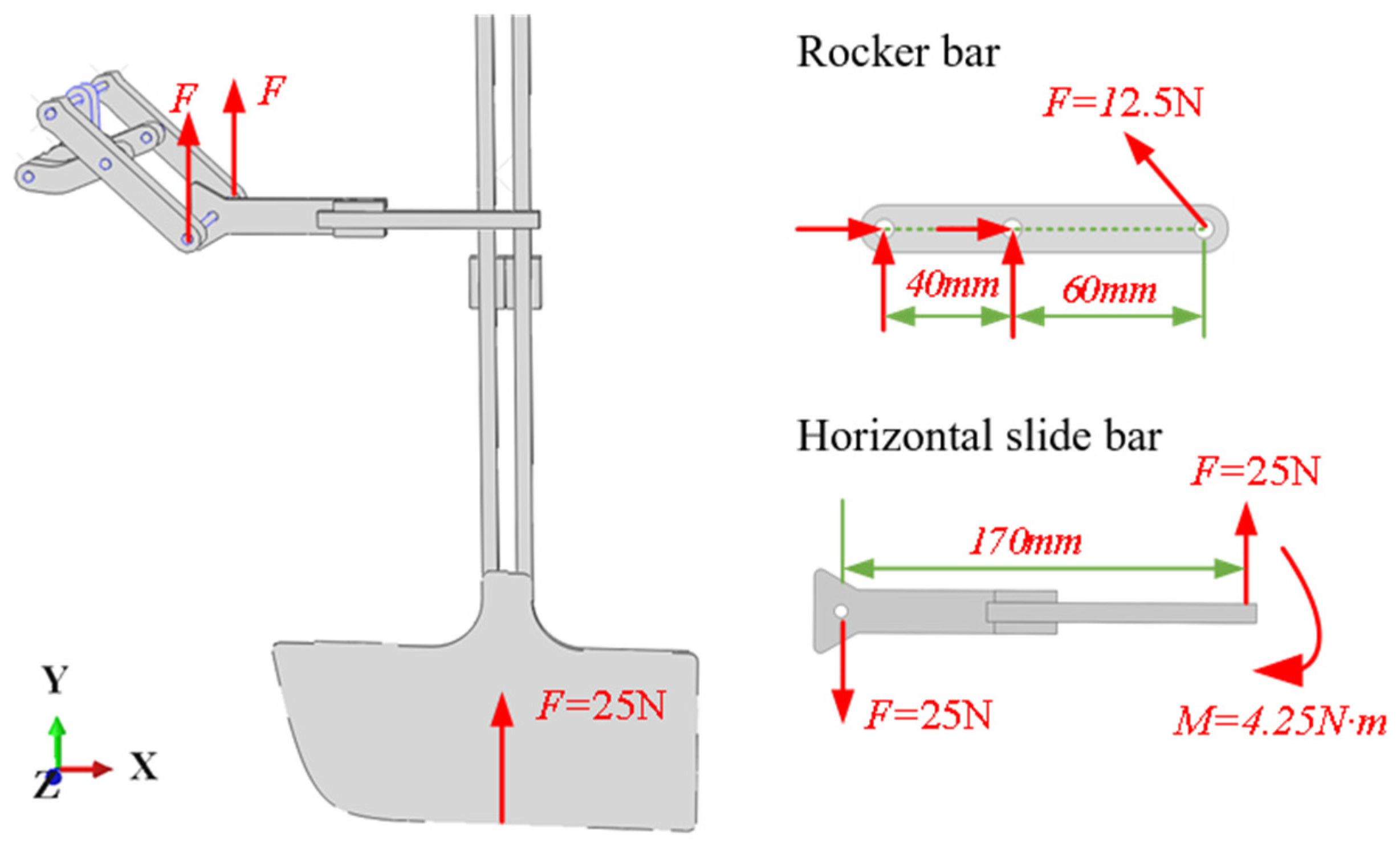
Intelligent and digital methods were applied to the design of this work. The maximum force load was 25N, and the strength of rocker and slide rod was checked according to the test result. The strength checking results show that the allowable stresses of the rocker rod and the horizontal slide rod are 27.3 MPa and 205 MPa, which are less than the allowable stresses and meet the strength requirements. Then, the rationality of the design was verified by the multi-body kinematics simulation analysis of the mowing mechanism by ABAQUS. The static simulation analysis of rocker and slide rod was carried out to verify the strength checking results. The simulation results show that the maximum stresses of the rocker rod and the horizontal slide rod are 1 MPa and 36 MPa, respectively, which verifies the strength checking results. Finally, according to the results of mechanism design, instrument analysis, strength check and simulation analysis, a physical prototype was manufactured and tested in the laboratory. The results show that the portable paving vehicle for straw checkerboard barriers can complete the task of paving straw checkerboard barriers automatically.
The portable paving vehicle for straw checkerboard barriers will perform an important role in windbreak and sand fixation. Compared to manual paving, it paves the straw checkerboard barriers automatically. Moreover, it provides a reference for the sand-control vehicles which pave straw checkerboard barriers to control desert. However, the current prototype is still mainly in the innovative configuration design stage of the mechanism, and the main innovation point is the innovation and application of the mechanism. Due to the limited conditions, many parts are not systematically carried out with rigorous and scientific parametric design. In addition, the current physical prototype is only designed based on the ideal laboratory environment, without considering the impact of bad weather and sand environment in the real desert on mechanical properties, such as the problem of sealing and lubrication of bearings in the sand.


