Abstract
Most studies related to aspects of wellbore stability, such as wellbore breakage, block dropping, and wellbore expansion, revolve around the physicochemical interaction between drilling fluid and surrounding rock, but relevant studies show that drill string vibration during drilling also has a crucial and even decisive influence on wellbore stability. In order to thoroughly explore the influence mechanism of drill string vibration on wellbore stability, our research group established a finite element flexible simulation model of drill string dynamics and used a storage downhole vibration measurement device to collect downhole real drilling vibration data to verify the correctness of the simulation model. Then, based on the critical conditions of wellbore breakage, a wellbore stability evaluation method was established, and the wellbore stability under different drilling parameters and drilling tool combination conditions was evaluated and analyzed. The research results play an important role in revealing the influence mechanism of drill string vibration on wellbore stability and can provide theoretical guidance for engineering problems such as wellbore instability risk assessment.
1. Introduction
In the petroleum industry, with the development of drilling technology, the proportion of deep wells and ultra-deep wells in oil drilling has gradually increased, and the phenomenon of drilling collapse and wellbore falling blocks leading to well leakage or jamming occurs from time to time and will lead to serious safety problems. According to a survey, the global oil industry spends more than USD 6 billion annually on wellbore stabilization, and the time lost due to wellbore instability accounts for 40% of the non-production time of drilling [1,2]. It can be seen that the stability of the wellbore during the drilling process is not only related to the drilling efficiency but also has an important impact on the economy and safety of drilling [3,4]. Therefore, it is of great engineering significance and economic value to study the mechanism of wellbore instability and the influencing factors and to propose measures to ensure the stability of the wellbore.
During the drilling process, the causes of the wellbore instability are usually divided into two categories [5]: one is the physicochemical interaction between the rock and the drilling fluid, which is particularly prominent in shale; the second is mechanical reasons, including the collision of drill strings on the wellbore, the difference in rock mechanics, and the distribution change in formation pressure. In 2003, Moheb A. Fam et al. [6] studied the coupling of physical and chemical properties leading to changes in the mechanical properties of mudstone, analyzed the process of mudstone diffusion under coupling, and speculated to explain the complex influencing factors of mud shale borehole stability under actual working conditions. In the same year, Oort et al. [7] conducted a study of shale wellbores, revealing complex links between transport processes (e.g., hydraulic flow, permeation, ion diffusion, and pressure), physical changes (e.g., hydraulic overbalance losses due to mud pressure infiltration), and chemical changes (e.g., ion exchange, shale water content changes, and expansion pressure changes). In 2003, Yu M. et al. [8] combined chemical and mechanical effects to establish a new model for evaluating wellbore stability. In 2004, S.K. Choi et al. [9] established a coupled partial differential equation under the assumption that shale is regarded as isotropic, considering the coupling of mechanical–thermal–physical–chemical properties, and developed a finite element solution software for simulating shale wellbore stability, which showed that drilling fluid temperature and its properties have a significant influence on wellbore stability. In 2006, M. Azeemuddin et al. [10] established pore pressure, maximum horizontal stress, and overburden stress models. The experimental results were calibrated with logging data, the drilling fluid density was predicted, and the conclusions were successfully applied in the field, which reduced the occurrence of well leakage accidents. In 2007, Perez et al. [11] performed an X-ray diffraction analysis on the water distribution of rock samples from different oil fields and elaborated on the effect of rock expansion on wellbore stability. From 2008 to 2012, AL-Bazali et al. [12,13,14,15] studied the stability of shale wellbores through experiments and simulations, and the analysis results showed that the coupling of the physical and chemical properties of drilling fluid would lead to large changes in the mechanical properties of the surrounding rock, thereby causing borehole instability. Based on this, researchers have conducted much research on the development of new drilling fluids by blending drilling fluid density and composition. From 2019 to 2012, Chenevert’s team [16,17,18] introduced silica into water-based drilling fluid, compared the effects of nanoparticles of different particle sizes and concentrations on the stability of shale wellbores, and found that nanoparticles had a good effect on shale gap plugging and could greatly reduce the permeability of shale. In 2012, McDonald [19] improved the traditional potassium silicate shale stabilizer and prepared a new potassium silicate shale stabilizer, which reduced the erosion effect of the filtrate and had a more prominent inhibitory effect on shale. In 2014, Moroni et al. [20] introduced nanoscale polymers into drilling fluids and found that nanoscale polymers can effectively enhance the stability of shale wellbores and plug shale gaps.
However, as the research on this issue deepened, researchers found that drilling fluid alone could not solve all the problems of borehole instability, especially in hard rock (igneous) formations, so the contact between the drill string and the wellbore began to attract the attention of researchers. In 1996, Dykstra et al. [21] proved that drilling pressure, drilling speed, and the mechanical properties of rock have an impact on the lateral vibration of the drill string, and the lateral vibration acceleration is generally about 20 g and up to 200 g in severe cases. Obviously, when the acceleration is large enough to cause the drill string to hit the wellbore, it will have a great impact on the stability of the wellbore. In 2002, Placido [22] et al. tested three wells in the Amazon, the lithology of which was all basalt, and the vibration of the bottom of the well was monitored by measuring the large hook load, speed, riser pressure, and torque. Through comparative analysis, it was found that the expansion of the well diameter and the vibration of the drill string were obviously correlated, and one of the wells did not show instability in the waterborne mud wellbore, which proved that the borehole instability was not caused by the physical and chemical interaction between the drilling fluid and the rock. In many cases, the impact of the drill string on the wellbore is the main cause of the instability of the wellbore. In 2003, Field et al. [23] measured lateral acceleration using drilling equipment (MWD) and found that the lateral acceleration range was 20–30 g when the wellbore was smooth, and when the wellbore became rough, the lateral acceleration surged to 70 g and even partially exceeded 80 g. In the same year, Melakhessou [24] established the dynamic concentrated parameter model of BHA, which fully considers the four independent degrees of freedom of the drill string lateral displacement, section rotation angle, tangential bending and torsion, and the frictional contact between BHA and the wellbore, and uses the Lagrange equation and the fourth-order Runge–Kutta method to establish and solve the equation. The results show that the initial configuration of BHA has a great influence on the vortex trajectory of the drill string. In 2009, Karkoub et al. [25] combined the proportional integral derivative and the lead–lag controllers with a genetic algorithm to design and optimize the controller, and the results showed that the designed controller could adjust the speed of the drilling column system to the safe range in time and shorten the drilling column vibration settling time, thus achieving the effect of reducing the vibration of the drilling column. In 2011, Liao et al. [26] explored the influence of speed and wellbore friction coefficient on the whirl of BHA and BHA vortex, established a BHA concentrated parameter model, and gave the optimal friction coefficient of the drill string during steady-state motion at the contact point. In 2012, Liao et al. [27] investigated the kinematic parameters of the drill column through a research method of numerical simulation and experimental mutual verification and found that the constructed reduced-order model could identify the characteristics of the collision between the drill column and the wellbore, and a small change in the rotational speed would have a large impact on the kinematic state of the drill column in the state of rotational speed and mass imbalance. From 2013 to 2014, Zhu et al. [28,29] established the collision model between the drill string and the wellbore and found that the impact force of the drill string had a greater influence on the stability of the wellbore. In 2017, Vijayan et al. [30] connected two disks with concentrated BHA mass through massless springs to establish a discrete mass–spring system to analyze BHA reverse whirl. The results show that the reverse whirl of BHA is greatly affected by the speed and axial force, and adjusting the ground speed and large hook load can weaken the reverse whirl of BHA, thereby improving the stability of the wellbore. In the same year, Khaled [31,32] and others developed a new model for predicting wellbore stability, and they found that whirl is directly related to wellbore instability, and collision with wellbore during drill string vibration is an important factor affecting wellbore stability. In 2018, Kapitaniak [33] used a new experimental rig to study the forward and reverse whirl of BHA and, for the first time, experimentally demonstrated the coexistence of the forward and reverse whirl of BHA. In addition, they established a double-degree-of-freedom mathematical model to describe the motion of the bottom plane, calibrated it through experimental results, and further studied it by numerical analysis. In 2020, Zheng et al. [34] proposed an observer-based control scheme for the continuous pole configuration of time-lag systems, which was verified to be effective in suppressing the viscous-slip vibration of the drilling column system. In 2023, Li et al. [35] proposed a set of partial differential equations considering the dynamic effects of continuous tubing drilling based on the beam unit bending theory for longitudinal loads to investigate the contact force between continuous tubing and wellbore in horizontal wells, and the results showed that the contact force between deformed continuous tubing and wellbore was related to the deformation compression rate.
In this paper, the influence of drill string vibration on wellbore stability is mainly studied, and the simulation mathematical model and the theoretical basis of wellbore stability are mainly described in Section 2. In Section 3, the modeling process and boundary conditions of drilling tool combinations are explained. In Section 4, according to the evaluation method of wellbore stability, the influence of different drilling tool combinations on wellbore stability is discussed. The main conclusions are presented in Section 5.
2. Model of the Influence of Drill String Vibration on Wellbore Stability
2.1. Force Analysis Model of Wellbore under Drill String Vibration
Due to the strong vibration of the downhole drill string, the movement state of the drill string in the downhole is more complicated, so the influence of drill string vibration (mainly lateral vibration) should be considered in the wellbore force model. Through analysis, it is found that the wellbore has constraints on the drill string (see Figure 1), and the current common constraint assumptions are as follows: (1) the wellbore is regarded as a rigid body and does not deform; (2) the wellbore is regarded as an elastomer; (3) the wellbore is regarded as a viscoelastic, and factors such as intrusion depth and damping are taken into account. Due to the variety of motion states of the drill string and the frequent nonlinear contact collision with the wellbore, the first two hypotheses are not suitable, so the third hypothesis method is adopted.
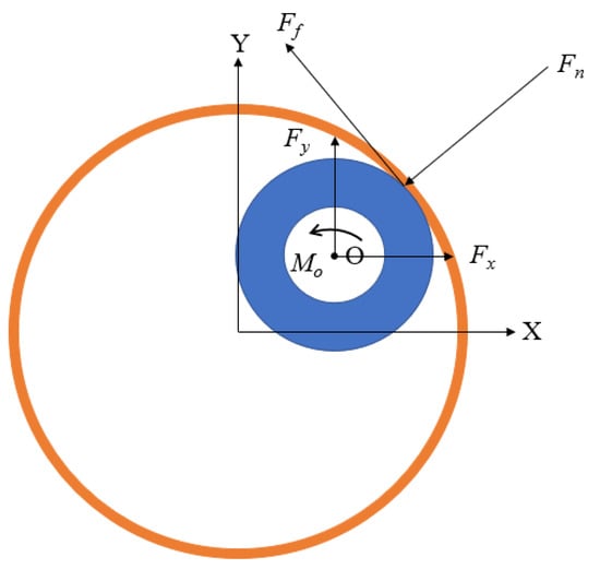
Figure 1.
Contact collision force diagram of drill column section.
The expression of the normal force is as follows:
In the formula,
- —Recovery factor;
- —Radial displacement of the center of mass of the drill string, m;
- —Damping factor;
- —Radial velocity of drill string center of mass, m/s;
- —Wellbore stiffness, N/m;
- —Wellbore diameter, m;
- —Drill string diameter, m.
where the recovery factor expression is as follows:
In the formula,
- —Pre-crash velocity, m/s;
- —Post-collision velocity, m/s.
The damping factor expression is as follows:
The tangential friction expression is as follows:
In the formula,
- —Coefficient of friction;
- —Stick–slip speed, m/s.
The expressions of frictional moment and frictional resistance in the Z direction are as follows:
2.2. Solving Method for Wellbore Instability
Professor Mohamed Shafik [32] of Cairo University summarized the previous research by comparing and analyzing the collision force between drilling tools and the wellbore and the strength of the wellbore rock mass, considering the influence of continuous vibration of the drill string on the rock mass strength, which will lead to the failure of the wellbore rock, divided into the following three situations:
- (1)
- The drilling tool collides with the wellbore, and the collision stress is large and exceeds the bearing capacity of the wellbore rock mass, resulting in the failure of the wellbore rock mass (indoor cyclic load test (marble)).
- (2)
- The drilling tool collides with the wellbore, and the collision stress is small and does not exceed the bearing capacity of the rock mass of the wellbore, but the multiple collisions between the drill string and the wellbore (the number of collisions exceeds 100 times) lead to a decrease in the strength of the rock mass of the wellbore and failure (thick-walled hollow cylinder cyclic loading (fatigue) test).
- (3)
- The collision stress between the drilling tool and the wellbore does not exceed the bearing capacity of the rock mass of the wellbore, but the multiple collisions between the drill string and the wellbore (the number of collisions exceeded 10,000 times) lead to a decrease in the strength of the rock mass of the wellbore and failure (cyclic load experiment (Buria sandstone)).
The criteria for determining whether a rock mass has failed are as follows:
In the formula,
- —The rock strength of the wellbore, Pa;
- —The contact area when the drill string collides with the wellbore, m2;
- —The minimum force required to destroy a rock, N.
The size of the contact area can be expressed by the following equation [36]:
In the formula, = 3.14;
- —Surrounding angle of drill string;
- —Drill string length, m.
In order to take advantage of Equation (8), it is necessary to know the size of and the law of its changes. It has been determined that the analytic formula for the surrounding angle is affected by certain factors, and its values are calculated as follows:
In the formula,
- —The chord length of the arc corresponding to the central angle , m.
The starting and ending points of the chord are determined by the arc length in contact with the wellbore relative to the drill string, which can be expressed by Equation (10):
In the formula,
- —Clay layer thickness, m;
- —The width of the ring gap, m.
The instability evaluation coefficient of the wellbore can be obtained using the following equation, which calculates the minimum force required to break the rock due to the collision of the drill string, drill bit, and wellbore, as calculated by Equation (7):
In the formula,
- —The instability evaluation coefficient of the wellbore;
- —The maximum collision force per meter, N;
- —The minimum force required to break the rock, N.
Due to the limitation of simulation time, there is no significant change in collision frequency in a short period. Therefore, it is necessary to make a reasonable prediction of the collision frequency.
In the formula,
- —Predict the number of collisions between drill string and wellbore per unit length;
- —The number of collisions per unit time per unit contact area;
- —The pure drilling time for drilling through the length of the BHA, s.
where
In the formula,
- —The number of collisions between the drill string and the wellbore per unit length in the simulation time;
- —Simulation time, s;
- —The number of units per contact area;
- —Mechanical drilling speed, m/s;
- —The length of the BHA, m.
where
In the formula,
- —Surface area of the inner wall of the wellbore per unit length, m2.
According to the contact area calculation formula, the contact area between the drill pipe and the drill collar and the wellbore is calculated, and the minimum force required to destroy the rock is calculated according to Equation (7). By combining the derivation of the first section, it can be seen that by obtaining the radial displacement and velocity of the center of mass at any moment on the cross-section of the drilling column, the collision force between the drilling column and the wellbore at that moment can be solved , which can be further combined with the collision frequency to derive the coefficient of the wellbore destabilization, so the establishment of a nonlinear dynamic model of the drilling column and its solution is especially critical.
In this paper, the nonlinear dynamic equation of the drill string is established based on the theory of finite element beam elements, and the Newmark method is used to solve the equation because the equation and solution method are more classic, and the derivation process will not be repeated.
3. Establishment of Drill String Dynamic Model
3.1. Basic Assumptions
During the drilling process under the combined action of drilling pressure and torque, the drill pipe is deformed under external loads and randomly collides with the wellbore, so the model is assumed as follows:
- (1)
- The deformation of the drilling string is limited, and when the combination of drilling tools is deformed, it is guaranteed to have random nonlinear contact collision with the wellbore;
- (2)
- The geometric dimensions and material properties of drill pipes and collars remain constant;
- (3)
- The wellbore is a viscoelastic body, the axis of the wellbore and the axis of the drill pipe should coincide in the initial state, there is a ring gap between the wellbore and the drill string, and the wellbore cross-section is circular;
- (4)
- Treat the surrounding rock within 1 m of the drill string as a whole;
- (5)
- Ignore the influence of drilling fluid on the drill string.
3.2. Establishing a Simulation Model
To avoid too long of a simulation time, we made a reasonable simplification of the drilling tool combination (see Figure 2), and then established the drill pipe and drill collar model. Firstly, the soild185 unit was used to establish the drill pipe and drill collar (see Table 1). According to the actual motion of the drill string on site, the degree of freedom of each member of the model was analyzed by finite element analysis software, and constraints were added at the appropriate position of the model (see Table 2). Finally, the other high-order modes were closed, and the first eight-order modes that play a major role in the deformation of the flexible body were taken into effect, and the establishment of the simulation model was completed (see Figure 3).
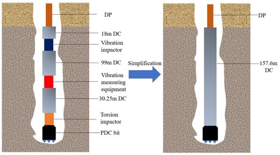
Figure 2.
Simplified schematic diagram of drilling tool combination.

Table 1.
Component modeling parameters.
Table 2.
Constraint relationships between components.
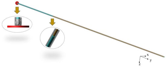
Figure 3.
Drill string dynamics simulation model.
In the actual drilling conditions on site, the drilling operation is mainly controlled by adjusting the drilling pressure and speed. Therefore, in this model, the drilling pressure is mainly applied through the weight of the drilling tool, and a one-way force is added to the top to control the drilling pressure. The top drive is equivalent to a rotary drive with single degrees of freedom to provide the rotational speed. The specific boundary conditions are given in Table 3 and Table 4.
Table 3.
Boundary conditions.
Table 4.
Contact force parameters.
According to the needs of simulation analysis, we created a single-centralizer drilling tool combination and a double-centralizer drilling tool combination concerning the above method and changed the position and size of the centralizer for simulation analysis, which will be explained in Section 4.
3.3. Model Reliability Validation
In a high-temperature and high-pressure downhole environment, based on fully investigating the research work of predecessors, our research group designed the high-frequency vibration measurement short section of this experiment (Figure 4) according to the construction situation on-site and used a high-precision triaxial accelerometer and gyroscope to measure and record the vibration of drilling tools.
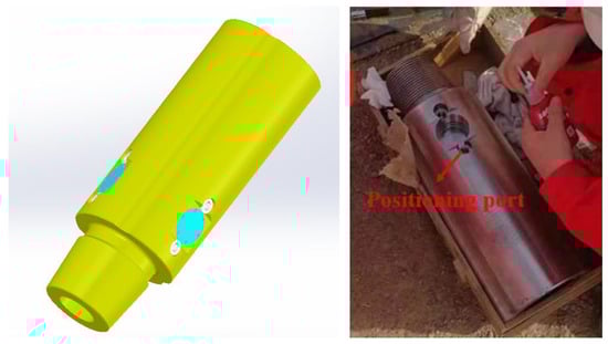
Figure 4.
Structure and physical diagram of vibration measuring device.
To minimize the influence of the shocker and torsion impactor on their measurement results, the measuring device was chosen to be positioned closer to the drill bit in this example, as shown in Figure 5.
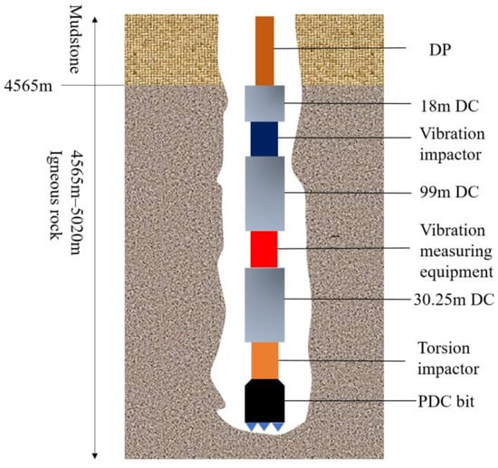
Figure 5.
Schematic diagram of drilling tool combination and installation of vibration measurement equipment.
When the vibration measurement device measures the vibration of the drilling tool, the two methods of high-frequency and low-frequency measurement are used at the same time, and the filter setting is carried out considering the influence of clutter generated by the downhole vibration of the drilling tool. The field data in this paper were collected by the No. 3 sensor high-pass filter (see Figure 6). The specific installation parameters are shown in Table 5 and Table 6.
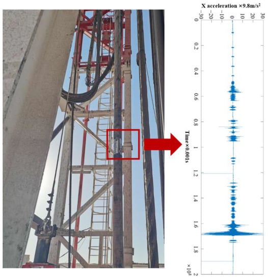
Figure 6.
Collection of downhole vibration data.
Table 5.
Drilling tool assembly dimensions.
Table 6.
Vibration measuring device measures sensor installation parameters.
To verify the accuracy and effectiveness of the simulation model, we used the real drilling data to confirm the accuracy of the simulation model. First, we obtained the triaxial acceleration of the real drilling data, and then used the simulation model to simulate the vibration of the drilling tool according to the corresponding mark point on the model according to the position of the sensor installation (see Figure 7). Finally, we compared the simulation results and the real drilling data to analyze the similarity of the two.
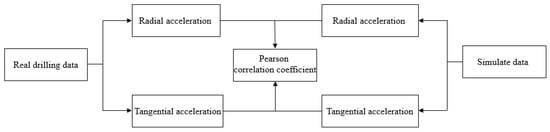
Figure 7.
Model verification technical route.
The arrangement of the sensor in the measuring device is as follows: Y-axis measurement of longitudinal acceleration, X-axis measurement of tangential acceleration, and Z-axis measurement of radial acceleration. The gyroscope direction of the sensor coincides with the positive direction of X, with a drilling pressure of 16 t and speed of 50 rpm. The intercepted radial and tangential acceleration and simulation data were compared and analyzed, as shown in Figure 8 and Figure 9.
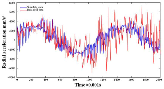
Figure 8.
Comparison of real drilling and simulated radial acceleration.
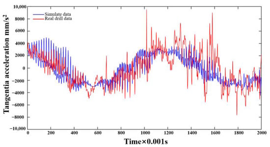
Figure 9.
Comparison of real drilling and simulated tangential acceleration.
From the measured and simulated radial and tangential acceleration curves, the overall trend is similar, the measured radial acceleration fluctuation range is −6~6 g, and the tangential acceleration fluctuation range is −8~10 g. The simulation radial fluctuation interval is −0.5~0.5 g, and the tangential acceleration fluctuation interval is −0.5~0.5 g. The Pearson correlation calculation is used to show that the correlation coefficient between the measured and simulated radial acceleration is 0.6569 and the tangential acceleration correlation coefficient is 0.6982, which can be seen in the Pearson correlation coefficient table; the two are strongly correlated.
In the acceleration solution, the actual downhole rotational angular velocity of the drill string can be solved by the tangential acceleration measured by the three-axis accelerometer, and the movement trajectory of the drill string during drilling at the measurement point position of the drill string can be calculated according to the three-axis acceleration. Through the comparison of the trajectory diagram (Figure 10), the analysis results of the measured data and the simulation show that whirl occurs at this point, and the whirl trajectories of the two are similar.
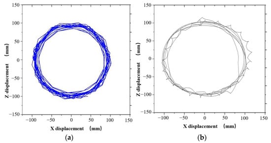
Figure 10.
Comparison of measured and simulated trajectory diagrams. (a) Measured trajectory diagram. (b) Simulated trajectory plot.
Combined with the comparison of tangential and radial acceleration, the accuracy of the nonlinear dynamic simulation model of the drill string and the reliability of the simulation results are verified.
4. Analysis of the Results
4.1. Analysis of the Impact of Borehole Risk Assessment Instability under Drill String Vibration
Using the calculation method introduced in Section 2.2, we calculated the contact area between the drill pipe, the drill collar, and the wellbore, and further calculated the damage force of the wellbore at different frequencies, as shown in Table 7.
Table 7.
Calculation results.
The dynamic model of the drill string in Figure 1, Figure 2 and Figure 3 is simulated by a drilling pressure of 16 t and rotational speeds of 20, 50, and 80 rpm, respectively, and the collision force is shown in Figure 11.
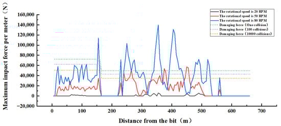
Figure 11.
Schematic diagram of collision force under different rotational speed conditions.
As shown in Figure 11, the collision between the drilling tool and the wellbore has the situation of one-time failure of rock mass and multiple collisions of rock mass failure. When the speed is 80 rpm, multiple positions can destroy the rock mass at one time, and the collision force of the drilling position (0–157.6 m from the drill bit) does not change much overall because the diameter of the drill collar is large, the stiffness is strong, and the collision force changes little in different positions. At the interface between BHA and the drill pipe, the collision force is as high as 113,853 N, far more than the force required for a failure, and the drill pipe part (157.6–657.6 m from the drill bit) generally changes greatly in the collision force and collision frequency, because the diameter of the drill pipe is smaller than the borehole, and the drill pipe accounts for most of the drilling tool combination during the drilling process, and the length is longer. When the speed is 50 rpm, the collision force is reduced compared to 80 rpm, and two positions can cause damage to the rock mass. When the speed is 20 rpm, only local collisions occur, and the collision force is small.
By analyzing the collision between the drilling tool and the wellbore, it is found that the collision force between the drilling tool and the wellbore will increase with the increase in speed. However, we can observe that the collision force is much more than the force required for a failure, but when the collision force is lower than the force required for a failure, the influence of collision frequency should be specifically considered; thus, it is extremely necessary to explore the collision between the drilling tool and the wellbore.
The dynamic model of the above drill string is further simulated and analyzed with a drilling pressure of 16 t and speed of 50 rpm, and the collision force and collision frequency are shown in Figure 12 and Figure 13.
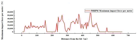
Figure 12.
Schematic diagram of collision force.
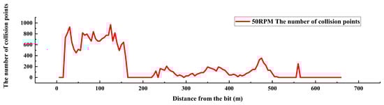
Figure 13.
Schematic diagram of collision frequency.
According to the schematic diagram of the collision force, it can be seen that the collision force at the drill pipe part is significantly greater than the collision force at the BHA, the collision force at the drill pipe part fluctuates greatly, and the maximum collision force of 57,126 N occurs at a distance of 450 m from the drill bit (on the drill pipe), reaching the force required for one failure. The collision force at BHA fluctuated smoothly between 0 and 34,816.5 N, and the maximum collision force at BHA was 34,816.5 N at 155 m from the drill bit.
Using Equation (13), the number of collisions at the same point is reasonably predicted (see Figure 14), and the collision frequency in each contact area is obtained. According to the number of collisions (the number of collisions between the drill collar and the wellbore is generally higher than the number of collisions between the drill pipe and the wellbore), the drilling collar part is more likely to collide with the wellbore in the simulation time than the drill pipe part, which is consistent with the research results that the drilling collar part has a larger diameter and more violent whirl than the upper drill pipe. Among them, the frequency of collision between drilling and the wellbore at 22.6 m from the bottom of the well reached 925 times, indicating that the collision between the drilling collar and the wellbore at the bottom of the well was fierce.
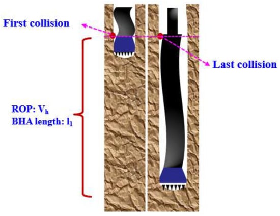
Figure 14.
Schematic diagram of collision frequency prediction.
Combined with the collision frequency and collision force, the wellbore instability evaluation table is established by Formula (12), as shown in Table 8.
Table 8.
Evaluation table of borehole instability.
According to the wellbore instability evaluation method, the safety evaluation of the wellbore is carried out (see Figure 15). It can be seen that the instability coefficient of 1 is exceeded at distances of 240, 265, 380, 375, 450, and 455 m from the drill bit, indicating that the wellbore has been damaged and dropped at these six points.
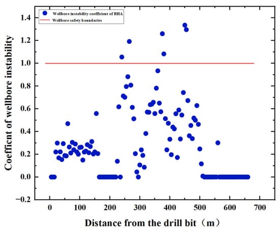
Figure 15.
Borehole instability coefficient with drilling pressure of 16 t and speed of 50 rpm.
4.2. Influence of Drill String Vibration on Wellbore Stability under Different Drilling Tool Combinations
4.2.1. Influence of Single Centralizer Placement on Wellbore Stability
In the actual drilling conditions, the appropriate drilling tool combination will be selected for different formations, which shows that the influence of drilling tool combination on the stability of the wellbore is more prominent, so we changed the drilling tool combination model and simulation analysis. The schematic diagram of drilling tool combinations is shown in Figure 16.
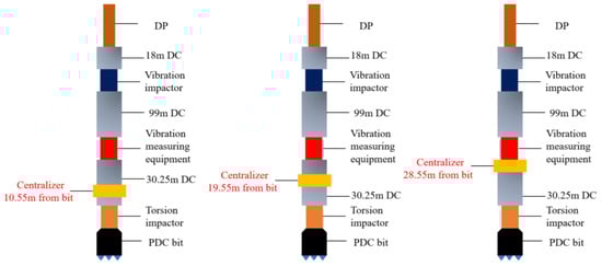
Figure 16.
Schematic diagram showing the placement positions of packed hole centralizers.
Numerical simulation was performed on the placement positions of three types of packed hole centralizers, shown in Figure 16, using a drilling pressure of 16 tons and a rotation speed of 50 rpm, and the collision force and frequency curves are shown in the following figures.
According to the schematic diagram of the collision frequency curves in Figure 17, on the whole, when the packed hole centralizer is installed 28.55 m from the drill bit, the collision frequency of the whole well is generally lower than that of the other two installation positions. At a distance of 105 m from the drill bit, the maximum collision frequencies of the three centralizers are 775, 538, and 452 times, showing that the collision frequency can be effectively reduced when the centralizer is installed 28.55 m from the drill bit, which is 42% and 16% lower than those installed 10.55 m and 19.55 m from the drill bit, respectively.
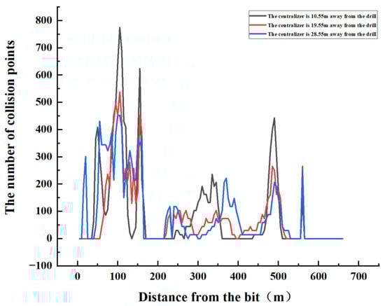
Figure 17.
Collision frequency curves.
According to the collision force curves of different installation positions of the full eye centralizer (see Figure 18), when the packed hole centralizer is installed 10.55 m from the drill bit, the collision force of the whole well does not exceed the force required for a failure, and the maximum collision force is 62,139 N at 60 m from the drill bit. When the packed hole centralizer is installed 19.55 m from the drill bit, five collision forces exceed the required force for one failure, and the maximum collision force of 84,158 N occurs 90 m from the drill bit. When the packed hole centralizer is installed 28.55 m from the drill bit, four collision forces exceed the required force for one failure, and the maximum collision force of 94,161 N occurs 230 m from the drill bit, which is far more than the required force for one failure. By comparing the three centralizer positions, it is found that the collision force of the packed hole centralizer installed 10.55 m from the drill bit is the smallest, and compared with the other two positions, its maximum collision force is reduced by 26% and 34%.
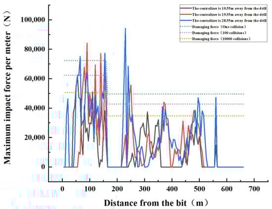
Figure 18.
Collision force curves.
By observing the schematic diagram of the wellbore instability coefficient (see Figure 19), it is found that when the packed hole centralizer is installed 19.55 m from the drill bit, a total of six places exceed the wellbore instability coefficient of 1. When the packed hole centralizer is installed 28.55 m from the drill bit, a total of eight places exceed the wellbore instability coefficient of 1, and when it is installed 10.55 m from the drill bit, there are no points exceeding the instability coefficient of 1 in the whole well. Compared with the placement position of the three types of centralizers, the centralizer is placed 10.55 m away from the drill bit, which can effectively ensure the stability and safety of the wellbore.
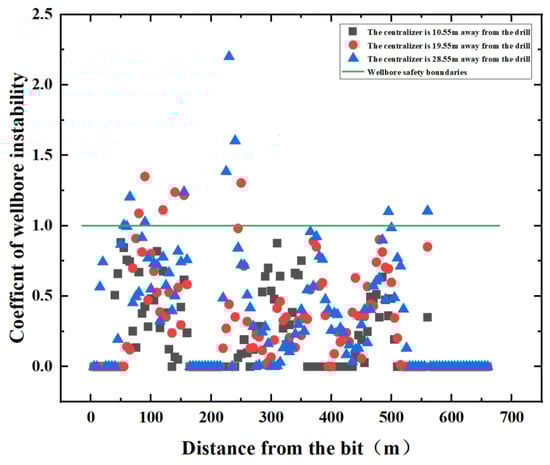
Figure 19.
Evaluation diagram of the wellbore instability coefficient.
4.2.2. Effect of Single Centralizer Size on Wellbore Stability
According to the above numerical simulation results, it is recommended to install the single centralizer at a distance of 10.55 m from the drill bit. The centralizers with packed hole sizes of 330.2 mm, 329.2 mm, and 327.2 mm are placed at a distance of 10.55 m from the drill bit, and the drilling pressure of 16 t and the speed of 50 rpm are used for simulation.
Observing the collision frequency diagram of the three centralizers (see Figure 20), the collision frequency of the 327.2 mm centralizer in the BHA part is significantly higher than the 330.2 mm and 329.7 mm centralizers, and the collision frequency reaches a peak of 1592 times at 105 m from the drill bit. The collision frequency of the full-eye centralizer at BHA is relatively reduced for the 327.2 mm centralizer, reaching a peak of 775 times at 105 m from the drill bit. The collision frequency of the 329.2 mm centralizer is slightly smaller than that of other sizes on the whole, reaching a peak of 645 times at 160 m from the drill bit, and its collision frequency is reduced by 59% and 17% compared with the other two sizes.
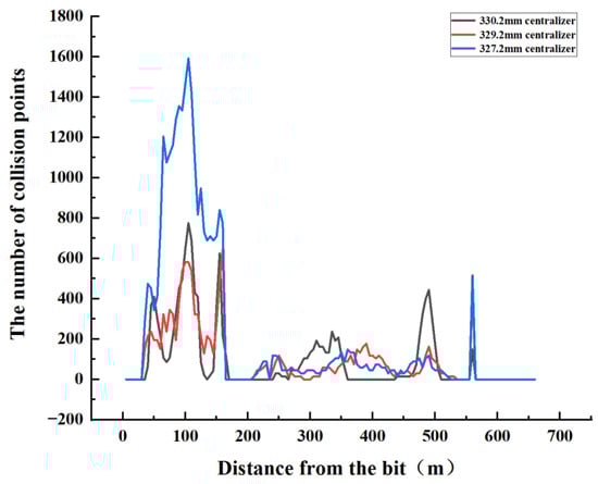
Figure 20.
Collision frequency diagram of different centralizer sizes.
According to the collision force diagram in Figure 21, it can be seen that the combination of drilling tools with centralizers with packed hole sizes of 330.2 mm, 329.2 mm, and 327.2 mm does not exceed the force required for a failure at BHA, and the combination of drilling tools with a 329.2 mm and 327.2 mm centralizer has a large collision force at the drill pipe and exceeds the force required for a single failure. The combination of drilling tools with a 329.2 mm centralizer has a maximum collision force of 82,789.5 N at 500 m from the drill bit, and the maximum collision force of 70,017 N occurs at 425 m from the drill bit with a combination of drilling tools installed with a 327.2 mm centralizer, which far exceeds the force required for a single failure.
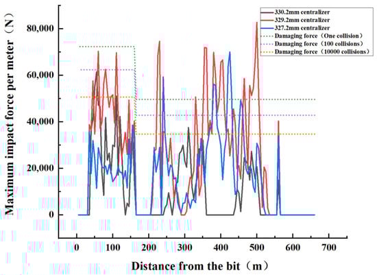
Figure 21.
Schematic diagram of collision force of different centralizer sizes.
In the schematic diagram of the wellbore instability coefficient in Figure 22, it can be seen that when the packed hole centralizer is installed, the instability coefficient of the whole wellbore is below 1. When the 329.2 mm centralizer was installed, the wellbore instability coefficient exceeded 1 in 20 places, and when the 327.2 mm centralizer was installed, the instability coefficient of the wellbore exceeded 1 in 6 places. It can be seen that the combination of drilling tools installed with 329.2 mm and 327.2 mm centralizers results in unstable wellbore phenomena at both the drill pipe and the drilling collar, so it is recommended to use a packed-hole centralizer.
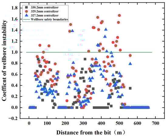
Figure 22.
Schematic diagram of borehole instability coefficient of different centralizer sizes.
4.2.3. Comparative Analysis of the Influence of Single and Double Centralizers on the Stability of the Wellbore
The effect of single and double centralizers on the stability of the wellbore is unknown. Thus, the combination of drilling tools, shown in Figure 23, was simulated and studied.
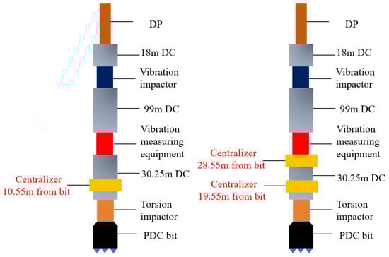
Figure 23.
Schematic diagram of the combinations of single- and double-centralizer drilling tools.
The combinations of single- and double-centralizer drilling tools were simulated with a drilling pressure of 16 t and speed of 50 rpm, and the collision frequency of the two was compared (see Figure 24). The collision frequency of the double-centralizer drilling tool combination reached a peak of 667 times at 80 m from the drill bit, indicating that the bottom movement of the well is complex, the collision frequency of the drill pipe part is relatively stable, and the curve fluctuation is not large. In the combination of single-centralizer drilling tools, the collision frequency at BHA was higher, reaching a peak of 775 collision frequencies at 105 m from the bottom of the well, and the collision frequency of the double-centralizer drilling tool combination was reduced by 14% compared with the single centralizer.
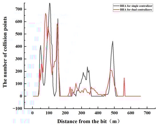
Figure 24.
Schematic diagram of collision frequency of single and double centralizers.
From the perspective of the collision force of single and double centralizers (see Figure 25), regarding the collision force of the combination of double-centralizer drilling tools, four places exceed the force required for one failure, and at 155 m from the drill bit, the maximum collision force is 75,730.5 N. The collision force of the whole well of the single-centralizer drilling tool combination did not exceed the force required for one failure, and the maximum collision force was 62,139 N at 60 m from the drill bit, which was reduced by 18% compared to the double-centralizer drilling tool.
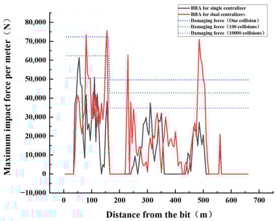
Figure 25.
Schematic diagram of collision force of single and double centralizers.
In the comparison and analysis of the wellbore instability coefficient of the combination of single- and double-centralizer drilling tools (see Figure 26), it is found that nine positions of double-centralizer drilling tools exceed the wellbore instability coefficient of 1, but the combination of single-centralizer drilling tools does not exceed the wellbore instability coefficient of 1 in the whole well. It can be seen that the stability of the wellbore of the single-centralizer drilling tool combination is significantly higher than that of the double-centralizer drilling tool combination.
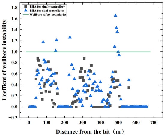
Figure 26.
Schematic diagram of borehole instability coefficient of single and double centralizers.
Based on the above, it is recommended to install a single centralizer with packed holes 10.55 m away from the bit, which can effectively maintain wellbore stability.
5. Conclusions
In this paper, the mechanism of borehole instability caused by drill string vibration is studied, a dynamic simulation model of the drill string is established, and the concept of wellbore stability coefficient is proposed. The wellbore stability is visualized and analyzed by the numerical simulation research method, and the following conclusions are drawn:
- (1)
- When the single centralizer is placed close to the drill bit and the wellbore instability coefficient is low, the stability of the wellbore is improved compared with other situations;
- (2)
- When the packed hole centralizer is installed close to the drill bit, it will further reduce the borehole instability coefficient and improve the stability of the wellbore;
- (3)
- Compared to the double-centralizer drilling tool combination, the wellbore will be more stable with the single-centralizer drilling tool combination;
- (4)
- It is verified that this method can predict wellbore stability and optimize the drilling tool combination and drilling parameters according to the wellbore stability.
Author Contributions
Writing—original draft preparation, Y.S.; methodology, Q.X.; supervision, J.W.; data curation, Y.L. and C.W. All authors have read and agreed to the published version of the manuscript.
Funding
This research was funded by [National Natural Science Foundation of China] grant number [42072341] And The APC was funded by [China University of Geosciences, Beijing].
Data Availability Statement
No new data were created or analyzed in this study. Data sharing is not applicable to this article.
Conflicts of Interest
The authors declare no conflict of interest.
Nomenclature
| The number of units per contact area | |
| Damping coefficient of drill string | |
| Recovery factor of drill string | |
| Drill string diameter, m | |
| Wellbore diameter, m | |
| The maximum collision force per meter, N | |
| The minimum force required to destroy a rock, N | |
| The normal force of the collision of the drill string with the wellbore, N | |
| The friction resistance in the Z-axis direction when the drill string collides with the wellbore, N | |
| Wellbore stiffness, N/m | |
| Drill string length, m | |
| The chord length of the arc corresponding to central angle , m | |
| The length of the BHA, m | |
| The frictional moment of the drill string, N · m | |
| Predict the number of collisions between drill string and wellbore per unit length | |
| The number of collisions per unit time per unit contact area | |
| The number of collisions between the drill string and the wellbore per unit length in the simulation time | |
| The instability evaluation coefficient of the wellbore | |
| The contact area when the drill string collides with the wellbore, m2 | |
| Surface area of the inner wall of the wellbore per unit length, m2 | |
| The pure drilling time for drilling through the length of the BHA, s | |
| Simulation time, s | |
| The velocity before the drill string collides with the wellbore, m/s | |
| The velocity of the drill string after collision with the wellbore, m/s | |
| Mechanical drilling speed, m/s | |
| Radial velocity of drill string center of mass, m/s | |
| Stick–slip speed of the drill string, m/s | |
| Surrounding angle of drill string | |
| The width of the ring gap, m | |
| Clay layer thickness, m | |
| Radial displacement of the center of mass of the drill string, m | |
| Coefficient of friction of the drill string | |
| The rock strength of the wellbore, Pa |
References
- Chao, W.; Mian, C.; Yan, J. A prediction method of borehole stability based on seismic attribute technology. J. Pet. Sci. Eng. 2009, 65, 208–216. [Google Scholar] [CrossRef]
- Zhang, J.; Lang, J.; Standifird, W. Stress, porosity, and failure-dependent compressional and shear velocity ratio and its application to wellbore stability. J. Pet. Sci. Eng. 2009, 69, 193–202. [Google Scholar] [CrossRef]
- Wang, F.; Liu, X.; Jiang, B.; Zhuo, H.; Chen, W.; Chen, Y.; Li, X. Low-loading Pt nanoparticles combined with the atomically dispersed FeN4 sites supported by FeSA-NC for improved activity and stability towards oxygen reduction reaction/hydrogen evolution reaction in acid and alkaline media. J. Colloid Interface Sci. 2023, 635, 514–523. [Google Scholar] [CrossRef] [PubMed]
- Li, Q.; Zhang, C.; Yang, Y.; Ansari, U.; Han, Y.; Li, X.; Cheng, Y. Preliminary experimental investigation on long-term fracture conductivity for evaluating the feasibility and efficiency of fracturing operation in offshore hydrate-bearing sediments. Ocean. Eng. 2023, 281, 114949. [Google Scholar] [CrossRef]
- Pašić, B.; Gaurina-Međimurec, N.; Matanović, D. Wellbore instability: Causes and consequences nestabilnost kanala bušotine: Uzroci i posljedice. Rud.-Geološko-Naft. Zb. 2007, 19, 87–98. [Google Scholar]
- Fam, M.A.; Dusseault, M.B.; Fooks, J.C. Drilling in mudrocks: Rock behavior issues. J. Pet. Sci. Eng. 2003, 38, 155–166. [Google Scholar] [CrossRef]
- Van Oort, E. On the physical and chemical stability of shales. J. Pet. Sci. Eng. 2003, 38, 213–235. [Google Scholar] [CrossRef]
- Yu, M.; Chenevert, M.E.; Sharma, M.M. Chemical–mechanical wellbore instability model for shales: Accounting for solute diffusion. J. Pet. Sci. Eng. 2003, 38, 131–143. [Google Scholar] [CrossRef]
- Choi, S.K.; Tan, C.P.; Freij-Ayoub, R. A coupled mechanical-thermal-physico-chemical model for the study of time-dependent wellbore stability in shales. In Elsevier Geo-Engineering Book Series; Elsevier: Amsterdam, The Netherlands, 2004; Volume 2, pp. 581–586. [Google Scholar]
- Mohiuddin, M.; Khan, K.; Abdulraheem, A.; Al-Majed, A.; Awal, M. Analysis of wellbore instability in vertical, directional, and horizontal wells using field data. J. Pet. Sci. Eng. 2007, 55, 83–92. [Google Scholar] [CrossRef]
- Diaz-Perez, A.; Cortes-Monroy, I.; Roegiers, J.C. The role of water/clay interaction in the shale characterization. J. Pet. Sci. Eng. 2007, 58, 83–98. [Google Scholar] [CrossRef]
- Al-Bazali, T.; Zhang, J.; Chenevert, M.E.; Sharma, M.M. Experimental and numerical study on the impact of strain rate on failure characteristics of shales. J. Pet. Sci. Eng. 2008, 60, 194–204. [Google Scholar] [CrossRef]
- Al-Bazali, T.; Zhang, J.; Chenevert, M.E.; Sharma, M.M. Factors controlling the compressive strength and acoustic properties of shales when interacting with water-based fluids. Int. J. Rock Mech. Min. Sci. 2008, 45, 729–738. [Google Scholar] [CrossRef]
- Al-Bazali, T.M.; Al-Mudh′hi, S.; Chenevert, M.E. An experimental investigation of the impact of diffusion osmosis and chemical osmosis on the stability of shales. Pet. Sci. Technol. 2011, 29, 312–323. [Google Scholar] [CrossRef]
- AL-Bazali, T.M. The consequences of using concentrated salt solutions for mitigating wellbore instability in shales. J. Pet. Sci. Eng. 2011, 80, 94–101. [Google Scholar] [CrossRef]
- Sensoy, T.; Chenevert, M.E.; Sharma, M.M. Minimizing Water Invasion in Shale Using Nanoparticles. In Proceedings of the SPE Annual Technical Conference and Exhibition, New Orleans, LA, USA, 4–7 October 2009. [Google Scholar]
- Cai, J.; Chenevert, M.E.; Sharma, M.M.; Friedheim, J. Decreasing water invasion into Atoka shale using nonmodified silica nanoparticles. SPE Drill. Complet. 2012, 27, 103–112. [Google Scholar] [CrossRef]
- Sharma, M.M.; Zhang, R.; Chenevert, M.E.; Ji, L.; Guo, Q.; Friedheim, J. A New Family of Nanoparticle Based Drilling Fluids. In Proceedings of the SPE Annual Technical Conference and Exhibition, San Antonio, TX, USA, 8–10 October 2012. [Google Scholar]
- Mcdonald, M.J. A Novel Potassium Silicate for Use in Drilling Fluids Targeting Unconventional Hydrocarbons. In Proceedings of the SPE Canadian Unconventional Resources Conference, Calgary, AB, Canada, 30 October 2012. [Google Scholar]
- Moroni, L.P.; Vickers, S.; Gray, C.; Davidson, M. Good Things Come In Little Packages: Nanotechnology for Reduction in Pore Pressure Transmission. In Proceedings of the SPE Annual Technical Conference and Exhibition, Amsterdam, The Netherlands, 27–29 October 2014. [Google Scholar]
- Dykstra, M.W.; Chen, D.; Warren, T.M.; Azar, J.J. Drillstring component mass imbalance: A major source of downhole vibrations. SPE Drill. Complet. 1996, 11, 234–241. [Google Scholar] [CrossRef]
- Pla´ cido JC, R.; Santos HM, R.; Galeano, Y.D. Drillstring vibration and wellbore instability. J. Energy Resour. Technol. 2002, 124, 217–222. [Google Scholar] [CrossRef]
- Field, D.J.; Swarbrick, A.J.; Haduch, G.A. Techniques for Successful Application of Dynamic Analysis in the Prevention of Field-induced Vibration Damage in MWD Tools. In Proceedings of the SPE/IADC Drilling Conference, Amsterdam, The Netherlands, 23–25February 1993. [Google Scholar]
- Melakhessou, H.; Berlioz, A.; Ferraris, G. A nonlinear well-drillstring interaction model. J. Vib. Acoust. 2003, 125, 46–52. [Google Scholar] [CrossRef]
- Karkoub, M.; Abdel-Magid, Y.L.; Balachandran, B. Drill-string torsional vibration suppression using GA optimized controllers. J. Can. Pet. Technol. 2009, 48, 32–38. [Google Scholar] [CrossRef]
- Liao, C.M.; Balachandran, B.; Karkoub, M.; Abdel-Magid, Y.L. Drill-string dynamics: Reduced-order models and experimental studies. J. Vib. Acoust. 2011, 133, 041008. [Google Scholar] [CrossRef]
- Liao, C.M.; Vlajic, N.; Karki, H.; Balachandran, B. Parametric studies on drill-string motions. Int. J. Mech. Sci. 2012, 54, 260–268. [Google Scholar] [CrossRef]
- Zhu, X.; Liu, W. The effects of drill string impacts on wellbore stability. J. Pet. Sci. Eng. 2013, 109, 217–229. [Google Scholar] [CrossRef]
- Zhu, X.; Liu, W.; Liu, Q. The mechanism and law of wellbore instability due to drill string impact in air drilling. Int. J. Oil Gas Coal Technol. 2014, 8, 153–181. [Google Scholar] [CrossRef]
- Vijayan, K.; Vlajic, N.; Friswell, M.I. Drillstring-borehole interaction: Backward whirl instabilities and axial loading. Meccanica 2017, 52, 2945–2957. [Google Scholar] [CrossRef]
- Khaled, M.S. A New Approach for Predicting Drillstring Vibration Impact on Wellbore Stability. In Proceedings of the SPE Annual Technical Conference and Exhibition, San Antonio, TX, USA, 9–11 October 2017. [Google Scholar]
- Khaled, M.S.; Shokir, E.M. Effect of Drillstring Vibration Cyclic Loads on Wellbore Stability. In Proceedings of the SPE Middle East Oil & Gas Show and Conference, Manama, Bahrain, 6–9 March 2017. [Google Scholar]
- Kapitaniak, M.; Vaziri, V.; Chávez, J.P.; Wiercigroch, M. Experimental studies of forward and backward whirls of drill-string. Mech. Syst. Signal Process. 2018, 100, 454–465. [Google Scholar] [CrossRef]
- Zheng, X.; Agarwal, V.; Liu, X.; Balachandran, B. Nonlinear instabilities and control of drill-string stick-slip vibrations with consideration of state-dependent delay. J. Sound Vib. 2020, 473, 115235. [Google Scholar] [CrossRef]
- Li, Z.; Chen, L.; Zhong, Y.; Wang, L. Study on Sinusoidal Post-Buckling Deformation of Coiled Tubing in Horizontal Wells Based on the Separation Constant Method. Machines 2023, 11, 563. [Google Scholar] [CrossRef]
- Makarenko, P.P.; Mande, A.R.; Gesackin, B.P.; Fu, Y. Determination of contact area between heavy drill pipe (УБT) and wellbore. Foreign Oilfield Eng. 1997, 13, 28. [Google Scholar]


Disclaimer/Publisher’s Note: The statements, opinions and data contained in all publications are solely those of the individual author(s) and contributor(s) and not of MDPI and/or the editor(s). MDPI and/or the editor(s) disclaim responsibility for any injury to people or property resulting from any ideas, methods, instructions or products referred to in the content. |
© 2023 by the authors. Licensee MDPI, Basel, Switzerland. This article is an open access article distributed under the terms and conditions of the Creative Commons Attribution (CC BY) license (https://creativecommons.org/licenses/by/4.0/).