Abstract
The aim of this paper is to present our research into the reduction of vibrations in induction motors. The use of power inverters results in the generation of electrical harmonics, which increase the level of the mechanical vibrations of electrical machines. To reduce these harmonics, we present a discontinuous pulse-width modulation (PWM) control strategy based on carrier-wave modulation applied to multilevel inverters. Using the proposed modulation technique, the amplitude of the electrical harmonics is reduced, as compared to other conventional techniques. These current harmonics produce the MMF (magnetomotive force) harmonics in the air gap, which are one of the main sources of vibrations. The control strategy makes it possible to vary the electrical spectrum at the output of a multilevel inverter by modifying a control parameter of the carrier wave in the PWM, thus avoiding the natural frequencies of mechanical resonance. The proposed technique also has the feature of attenuating the total harmonics distortion of the voltage of the multilevel inverters, as well as the achievement of a higher RMS value of the output voltage for the same DC level. Laboratory results for an induction motor with different modulation strategies, applied in a multilevel inverter and compared to the strategy presented, are attached.
1. Introduction
The induction motor is the most widely used type of mechanical drive equipment in industrial environments, and it has positioned itself as an important component in fields such as smart transport and machine manufacturing [1]. These devices need to be controlled using power converters that regulate their torque and speed. These converters generate a pure non-sinusoidal power supply that produces electrical harmonics. These harmonics produce vibrations and noises in the motors, and they can deteriorate them and reduce their life cycles [1,2]. Vibration is a key component in the operation of the motor. If vibration sources are not detected early on, this will lead to the gradual deterioration of the machine, reaching a point where irreparable damage occurs, resulting in motor shutdown, potentially causing accidents.
The steady-state vibration of the engine can be influenced by several sources in addition to those originating from the electromagnetic field. Thus, vibrations originating from the mechanical base of the system, the type of anchoring to the ground, or other devices that are mechanically connected to the motor can be the sources of such vibrations [3]. Additionally, high-voltage switching through pulse-width modulation (PWM) of the motor controllers produces harmonics which generate MMF that, in turn, cause undesired torques during operation.
Considerable focus has been placed on vibrations caused by electromagnetic phenomena, particularly those resulting from harmonics. The slotting effect and the magnetic interaction between the stator and rotor have received significant attention in this regard. In [4], a model is introduced to precisely calculate the electromagnetic parameters associated with vibroacoustic phenomena. This model treats each spatial harmonic generated by the stator winding MMF individually, employing the current-sheet approach to determine the radial and tangential forces present in squirrel-cage induction motors.
The proposal of the present work is to offer a possible solution for avoiding these harmonics, and therefore vibrations, in a motor, for which the use of multilevel power converters (MLI), together with an optimized control technique, is proposed.
The multilevel inverter is a power converter that provides a suitable solution for synthesizing an output voltage to reduce the harmonic content of voltage and current in medium- and high-power systems [5]. The most common topologies of these converters consist of connecting individual inverters, “called stages”, to provide an output voltage that is the result of associating the voltages of the different stages. The advantages of multilevel converters over two-level converters include a lower dv/dt, lower switching losses, a higher fault-tolerance capability, and better output waveform quality [6]. Due to this last advantage, the output filter will also have a smaller volume.
There is a wide range of multilevel inverter topologies [7,8], with the most prevalent voltage source topology being the neutral-point diode converter (NPC) [9], some of them having parallel structures for high-power motors [10]. Other relevant types of topologies would be the flying capacitor converter (FCC) [11] and the modular multilevel converter (MMC) [12,13]. Finally, the cascaded H-bridge converter (CHB) [14], with different control techniques [15] and with symmetrical and asymmetrical power supplies [16], is more applicable as the number of levels increases.
In this research paper, we have opted to use a cascaded H-bridge multilevel inverter for our comparative analysis (see Figure 1), which boasts several advantages over alternative topologies (NPC and FCC). The CHB inverter possesses modularity and enhanced controllability due to the identical structure of each stage. Furthermore, it enables the attainment of multiple levels using minimal components. These alleviate switching losses in the utilized devices, thereby augmenting circuit reliability and efficiency [17]. Consequently, this topology finds extensive utilization in industrial applications [8].
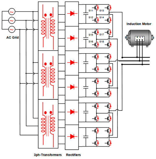
Figure 1.
CHB multilevel power inverter.
One of the applications of the CHB inverter is the provision of power to high-power motors, which is supplied at elevated voltages to minimize current in the windings. This necessitates multiple stages for each phase. It is widely recognized that using such devices for the speed or torque control of AC electrical machines can lead to increased vibrations.
Regarding modulation techniques, the literature offers numerous options for MLI control. The most commonly employed techniques include carrier-based PWM [18], space vector modulation [19,20], and selective harmonic elimination [21,22]. Carrier-based modulation has given rise to highly popular techniques for MLIs, such as phase-shifted pulse-width modulation (PS–PWM) and carrier-level shift pulse-width modulation (LS–PWM) [23,24]. Other techniques involve modifying the carrier-signal frequency and modulating the signal harmonics’ amplitudes to reduce losses and enhance the electrical parameters of the modulated waveform [25]. In [26], an LS–PWM technique is utilized, where the reference signal is vertically shifted to derive the switching signal for the MLI. As a level shift exists between the carrier signals, higher voltage distortion occurs, which is not the case with PS–PWM.
In summary, all electric drives contribute to increased vibrations in electromagnetic circuits [27]. However, the level of these vibrations can be mitigated depending on the control technique and topology employed [28,29]. Here, the proposed strategy focuses on cascaded or H-bridge inverters and utilizes an efficient PS–PWM technique. This technique not only ensures a balanced power distribution among the cells but also results in reduced voltage distortion and the effective suppression of harmonic current distortion. These characteristics play a crucial role in attenuating the vibrations generated by the motor. The vibration results and quality parameters of the inverter output waveform obtained through the proposed modulation technique have been compared with results from other techniques documented in the scientific literature, which have shown promising outcomes. Specifically, the compared techniques include amplitude-shifted modulation in the carrier waves (Figure 2a), phase-shifted modulation in the carrier waves (Figure 2b), and phase-shifted modulation with harmonic injection into the modulating wave (Figure 2c). To the best of our knowledge, there is currently no recent research in the technical literature on reducing vibrations in induction motors using multilevel converters and PS–PWM techniques.
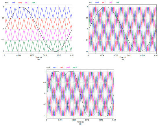
Figure 2.
Multilevel inverter modulation: (a) with amplitude shift; (b) with phase shift; (c) with phase shift and injection of harmonics.
The remainder of the present paper is structured as follows: Section 2 provides an introduction to the vibration frequencies anticipated when feeding an induction motor with either a sinusoidal source or an inverter generating specific sets of harmonics.
In Section 3, the proposed technique for controlling multilevel inverters is presented, outlining its fundamental principles. The generation of the signals applied to the IGBT gate terminals and the waveform at the inverter’s output, based on the control parameter, is described. Additionally, the section illustrates the relationship between the instantaneous frequency of the carrier wave and the modulating signal in relation to the control parameter.
Subsequently, Section 4 presents and analyzes the laboratory results. It showcases the equipment required to generate the control waves for the tested strategies, including the vibration meter setup and the signal analyzer used to record voltage and current waveforms, along with their corresponding electrical spectra. Lastly, Section 5 summarizes the conclusions drawn from the research.
2. Natural Frequencies and Axial Stress Generating MMFs on the Stator
There are two sources of vibrations that occur in an electrical machine, depending on their origin. The first type is composed of axial forces of aerodynamic and mechanical origin and by the eccentricities of its axis (mainly, the fan, bearing, activation of mechanical resonances, and the phenomenon of magnetostriction). They are low-frequency, depend on the degree of saturation in the magnetic circuit of the machine, and the load level has a limited effect on them. Electrical harmonics of the spatial type, due to the restriction of the maximum number of slots and coils (size functions), are another source of vibrations and noise. On the other hand, when an inverter is used to power the motor, the produced electrical harmonics are a new source of vibrations. This last source of vibrations will be a function of the modulation technique used with the power switches of these inverters, the carrier frequency, and the speed set for the motor shaft. These vibrations depend on the current and, therefore, on the load level. When any of these electrical harmonics activate a natural resonance frequency of the engine, the level of vibration can be critical to the lifetime of the machine.
The calculation of the natural resonance frequencies of an induction motor structure can be carried out with the equations found in the technical literature [30]. If the stator length is greater than its mean diameter, , good results are obtained for these frequencies by considering the electrical machine as a cylinder of infinite length. For circumferential modes of vibration where m ≥ 0, the frequency can be expressed as follows:
where is Poisson’s ratio, is the modulus of elasticity, and is the root of the equation of movement. Circumferential mode forces m to zero, and therefore, = 1. For m ≥ 1,
and the dimensionless thickness parameter is
where is the stator thickness. On the other hand, a housing with a bell-shaped end behaves like a cylinder with both ends mechanically constrained. There will be two axes of displacement: a radial one with circumferential vibrational modes, m, “breathing” m = 0, elliptical m = 1, etc., and another axial one with modes n being equal to 1 onwards. The characteristic equation of the movement of a cylinder of finite length, , supported on legs according to the Donnell–Mushtari theory [30], will be of the following type:
where Pmn are the roots of the equation of motion. The housing resonance frequencies have the same structure as those in Equation (1). Three groups of roots correspond to the displacement in the three orthogonal directions in Equation (4), for which the smallest real root determines the natural deflection frequency of the frame, with that being:
where C2, C1, and C0 are the coefficients of the polynomial described in (4), is the average radius of the casing, is the average diameter of the casing, is the thickness of the casing, is its length, is its Poisson’s ratio, and is the density. The circumferential vibrational modes, m equal to 0 onwards (natural numbers), should be calculated for each axial vibrational mode, n.
If the motor is fed from a balanced three-phase power supply, the only harmonics that appear are spatial harmonics. The most significant of these spatial harmonics are the tooth harmonics. They are present when the machine is fed with a three-phase network, and they depend on the number of phases and poles and the winding factor of each harmonic:
with p being the number of pairs of poles, s1 being the number of stator slots, and k equaling the natural numbers from 1 onwards. The amplitude of the vibrations, A, shall be proportional to the products of the terms of the flux densities:
where B is the magnetic flux density in the magnetic circuit of the machine, α is the angular position with respect to a reference, and t stands for time, such that the amplitude and frequency of these vibrations must consider the product of all the harmonic terms of the induction in the machine. Other harmonics are due to the phenomenon of magnetostriction and bearing rollers.
When the machine is powered by a power inverter, the radial forces resulting from the electrical harmonics are caused by the interaction between the stator harmonics and their corresponding time harmonics, resulting in a specific frequency:
where f is the frequency of the fundamental component of the modulated waveform, k is the series of natural numbers, and m1 is the number of phases of the stator. Similarly, the harmonic decomposition of the rotor currents will result in vibrations at specific frequency values:
with s2 being the number of rotor slots. In addition, frequency vibrations are generated as a result of the mutual influence between the frequency of the carrier signal, fc, with the time harmonic frequency of the modulating wave. Its vibrational mode is zero, and therefore, the possibility of producing high vibrations is greater since these are reduced with the order of the vibrational mode. Their frequencies can be obtained as follows:
where fr is the frequency of the force density. If n is even, n′ is odd, and if n is odd, n′ will be even. Therefore, electrical harmonics can be expected at the following frequencies: fc ± 2f, fc ± 4f, 2fc ± f, 2fc ± 3f, and so on. In other words, it can be anticipated that the vibrational harmonics generated by the inverter will manifest themselves at frequencies that are either slightly above or below the frequency of the electrical spectrum of the modulated wave applied to the electric motor. When an electrical harmonic is present at a frequency of f, the corresponding vibrational harmonic will manifest itself at a frequency of either (f + 1) or (f − 1). This is due to the axial force densities being derived from the multiplication of all the flux densities within the air gap.
Power inverters manipulate the voltage level and frequency in the stator of the machine, resulting in an electrical spectrum characterized by amplitudes and frequencies that are contingent upon the modulation technique employed. The existence of these harmonics will produce energy losses, reduced efficiency, and pulsating torques that translate into vibrations in the machine. One common approach to mitigating the adverse effects of these electrical harmonics is to raise the frequency of the carrier signal. However, this frequency is constrained by the maximum switching frequency of the circuit breakers and, in turn, increases the losses incurred by the inverter. Another approach, enabled by the decreased cost of power switches, is to interconnect multiple elementary stages in a series, each utilizing one or more separate sources. This arrangement reduces the number of switching for each IGBT and enables a higher carrier frequency in the PWM technique, thereby amplifying the voltage and power capacities of the electrical machine.
In the case of high power and voltage requirements, minimizing switching losses becomes crucial. This is achieved by minimizing the frequency of the carrier wave in the inverter modulation. However, this strategy amplifies the likelihood of mechanical resonances in the system caused by the time harmonics generated by the inverter. Hence, for such applications, the control strategy assumes special significance.
3. New HIPWM–FMTC Strategy Applied to Multilevel Inverters
The HIPWM–FMTC (harmonic injection PWM–frequency-modulated triangular carrier) technique generates the output voltage of an inverter by comparing a modulating wave that injects harmonics with a triangular carrier wave that is frequency-modulated. The frequency of the carrier waveform is not constant but varies based on a periodic function, specifically a squared cosine, which is synchronized with the phase of the modulating waveform. The employed strategy involves increasing the number of switching pulses when the slope of the modulating waveform is at its maximum or minimum and then gradually reducing it to zero when the slope is at its lowest (near the maximum and minimum phases). However, the total number of pulses in a complete period is maintained in relation to any conventional PWM technique. This strategy is commonly referred to in the technical literature (within the context of three-level inverters) as the HIPWM–FMTC (harmonic injection PWM–frequency-modulated triangular carrier) technique [31].
A modified version of the HIPWM–FMTC technique has been proposed, which introduces a parameter that interrupts the triangular carrier wave during certain time slots of the modulating wave. This modification allows for an increase in the instantaneous switching frequency in some time slots while eliminating switching in others [32]. When applied to multilevel inverters, this technique is referred to as HIPWM–FMTC truncated or HIPWM–FMTCt [33]. The effect of overmodulation to improve the HIPWM–FMTC technique in three-level inverters has also been investigated [34]. The instantaneous pulsation of the carrier wave, denoted as ωi, becomes a discontinuous function that is synchronized with the modulating wave ωm. It can be defined as follows:
The modulating wave and the instantaneous pulse of the carrier wave, ωi, need to be synchronized functions, as depicted in Figure 3. The parameter K, which represents the truncation level, is a real number ranging from 0 to 1, and it is independent of , which represents the number of pulses per period. On the other hand, AM is a parameter that determines the middle of the maximum frequency of the carrier wave. By selecting appropriate values for AM, K, and the frequency modulation order, , the instantaneous maximum frequency can be adjusted. The combination of these parameters (AM and K) enables the modification of the electrical spectrum without altering the value of . Thus, after setting a value for , each value of K will correspond to a specific value of AM. It is important to note that when Equation (12) yields negative values, ωi will be nullified during those intervals.
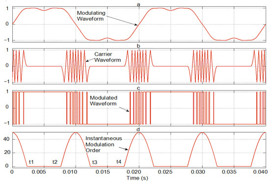
Figure 3.
Simulation of the proposed PWM generation: (a) modulating waveform for f = 50 Hz; (b) HIPWM–FMTCt carrier (K = 0.55 and AM = 111.15125); (c) phase voltage for an H-bridge; (d) instantaneous modulation order.
Note that the frequency modulation order, , is the mean value of a periodic function M(t), thus, the instantaneous frequency modulation order, which will be null between t1 and t2 and between t3 and t4 for each period of the modulating wave to avoid such switching. During a period of the modulating wave, both M and will be the same value:
where Tm is 2π/ωm. The frequency modulation order, , must be set to a natural number, and if the motor is three-phase, it must be set to an odd value that is a multiple of 3.
The primary objective is to ensure that the maximum instantaneous frequency of the triangular carrier wave aligns with the points where the modulating sine wave exhibits the steepest slope (0 and π radians). The frequency of the carrier wave gradually decreases following a quadratic cosine function around these phases and eventually reaches zero within a specific time interval determined by the truncation factor, as described by Equations (12) and (13). In the case of K = 0, the carrier wave frequency theoretically becomes zero only at the phase values of the modulating wave: π/2 and 3π/2. In other words, the instantaneous pulsation of the carrier wave is never eliminated. As K increases from 0 to 1 (excluding 1, which would imply an infinite instantaneous carrier wave frequency), the proposed technique ensures that the carrier frequency becomes zero for progressively longer time intervals centered around the T/4 and 3T/4 of the period of the modulating wave. The frequency of the carrier waveform increases precisely around the 0 and T/2 of the period of the modulating wave, which correspond to the points of its steepest slopes. This approach is adopted because the modulating wave undergoes faster slope changes at these phase values, thereby providing a more accurate representation of the carrier wave’s shape in the modulated waveform. As shown in Figure 3, K = 0.55 and = 15 (AM = 111.15125); for slightly less than half of the period, there will be a modulated triangular carrier, and during the other, slightly more than half, of the period, switching will be canceled. The maximum excursion of the carrier frequency will be AM·ωm·(1 − K) = 50.01806·ωm. Therefore, t1 is 2.3426 ms, and t2, t3, and t4 will be 7.6574, 12.3426, and 17.6574 ms, respectively. For other values of K, regardless of the value of M, the times t1 to t4 will change. For example, for K = 0.5, they will be 2.5, 7.5, 12.5, and 17.5 ms.
By employing this technique, the maximum frequencies of the carrier will be up to π times depending on K, instead of , as would be the case in a sinusoidal PWM technique. In Figure 3, the area beneath the curve of the instantaneous modulation order corresponds to = 15 and K = 0.55. It is possible to identify the modulating, carrier, and modulated functions, as well as the function of the instantaneous modulation order. In Figure 4a, the combined modulating and carrier functions can be observed as a function of time. Figure 4a,b illustrate the signals driving the gates of the 2-stage H-bridge transistors corresponding to one phase of the multilevel inverter shown in Figure 1. The pulse train that triggers the S1_1 base is generated by comparing the modulating signal with the phase 0° harmonic injection with the phase 0° carrier. Similarly, the pulse train that triggers the base of S1_3 is obtained by comparing the modulating signal with the 180° phase harmonic injection with the 0° phase carrier. The pulses resulting from the comparison between the modulator and the 0° and 90° phase carrier stimulate S1_5. Finally, the 180° phase modulator, as compared to the 90° phase carrier, generates the pulses that drive the gate of S1_7. The timing of these signals is shown in Figure 4c.
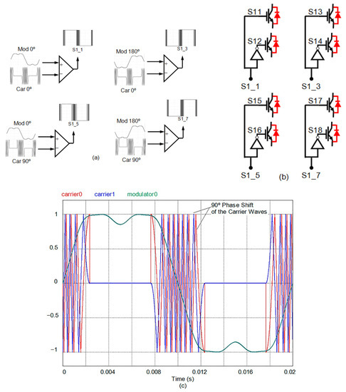
Figure 4.
(a) Single-phase pulse generation; (b) gate signals for IGBTs; (c) modulator and carrier waveforms for f = 50 Hz, = 15 for the proposed technique (K = 0.55 and AM = 111.1513π).
Table 1 shows how some variables evolve against K when ωm are set to 100π rad/s while is fixed at 11 and 15, respectively. The variables presented are t1 (a quarter of the time that makes possible the per-period switching of the output waveform), AM, and AM·(1 − K), with the latter being the instantaneous modulation order of maximum frequency. The maximum carrier frequency is fm multiplied by AM·(1 − K). Figure 5a shows the simulation of two periods of the three-line voltage of the modulated waves, where it can be seen how the switching frequency is higher for values close to zero. Moreover, it decreases until the commutations in the maximum and minimum values disappear. Figure 5b illustrates how the amplitude of the 17th harmonic, as a percentage of the fundamental, changes with respect to the K-value. This is true for the fundamental term as well as for the rest of the harmonics.

Table 1.
AM, t1, and AM·(1 − K) for different values of K with M = 11 and M = 15.
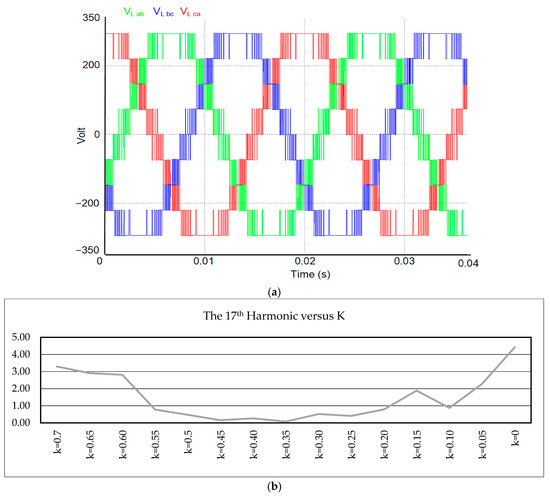
Figure 5.
(a) Modulated line voltage waveforms with HIPWM–FMTCt strategy (K = 0.55, f = 50 Hz, and = 15); (b) amplitude for the 17th harmonic with respect to the K-value.
4. Results
An AEGTM 380/220 V, 1000 W, and 4-pole asynchronous motor with s1 = 36 slots in the stator and s2 = 26 slots in the rotor was used to measure vibrations in the laboratory. The multilevel inverter was built on the basis of GUASCH S.A.TM modules, which have GPT-IGBT transistors. The GUASCH S.A.TM GPT-IGBT module was used to implement the multilevel inverter. It offers a power stack of insulated gate bipolar transistors (IGBTs) for motor control. The power system consists of three-phase bridge rectifiers, capacitor banks, IGBTs with forced-air-cooled heat sinks, opto-coupled drivers, output phase current sensors, DC-link current, and a voltage sensor. The maximum voltage that the DC-link can withstand must not exceed 750 V, and the maximum RMS current in each phase is 32 A.
The hardware system for generating control signals for each of the H inverters that make up the multilevel inverter is based on the NI9154 card from National InstrumentsTM, on which a LabviewTM platform has been developed for generating the PWM techniques that control the different H-bridges of the multilevel inverter. A Chauvin ArnouxTM C.A. 8336 was used to measure the output current harmonics of the multilevel inverter. To measure the vibrations of the machine, a sensor PCBTM Piezotronics Accelerometer model number 333B50 was connected to a METRAVIT Symphonie model 01 dB sound-level meter. Figure 6a illustrates the multilevel power inverter and the NI9155 control equipment, and Figure 6b illustrates the sensor on the AEGTM asynchronous motor.
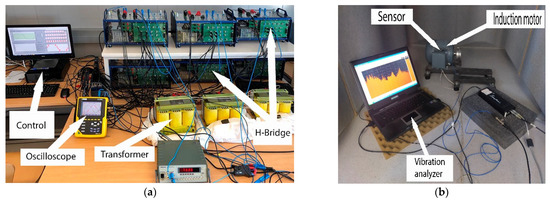
Figure 6.
Implementation: (a) multilevel inverter, NI9154 network analyzer, National InstrumentsTM NI9154 board with LabviewTM system for control of the multilevel inverter bridges; (b) motor with PCBTM Piezoelectric Accelerometer model 333B550 and vibration analyzer.
Figure 7, Figure 8, Figure 9 and Figure 10 illustrate the waveforms and amplitudes of the current spectra (%) of the different PWM techniques, SPWM-I, SPWM-II, and SPWM-III, and the HIPWM–FMTCt technique with K = 0.55 presented in this paper.
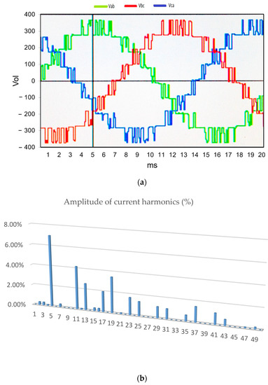
Figure 7.
(a) Line voltage output (220 V RMS) with SPWM-I strategy; (b) amplitude of current harmonics (%): V = 220 V RMS of the fundamental term.
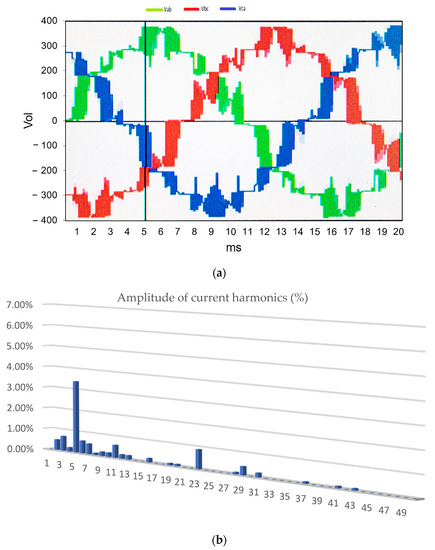
Figure 8.
(a) Line voltage (220 V RMS) of the multilevel inverter with SPWM-II strategy; (b) amplitude of current harmonics (%): V = 220 V RMS of the fundamental term.
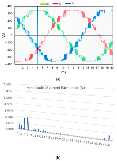
Figure 9.
(a) Line voltage output of the multilevel inverter with SPWM-III technique; (b) percentage amplitude of current harmonics (V = 220 V RMS of the fundamental term).
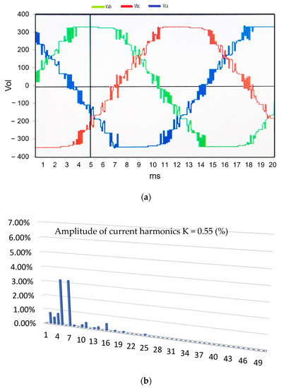
Figure 10.
(a) Line voltage output of the multilevel inverter with technique HIPWM–FMTCt, with K = 0.55 and M = 15; (b) percentage amplitude of current harmonics (V = 220 V RMS of the fundamental term).
The SPWM-I technique corresponds to PWM with an amplitude-shifted triangular carrier wave. This is, perhaps, the most common technique in the technical literature on multilevel inverters. Figure 7a shows the output waveform of the multilevel inverter, and Figure 7b shows the harmonics electrical spectrum of the output current of this waveform. The fundamental harmonic, in terms of the percentage of output voltage, is maintained at 220 V RMS.
The following SPWM-II technique corresponds to a phased-shift for the triangular wave carriers and a sine modulator wave. As in the previous technique, Figure 6a,b correspond to the inverter output voltage waveform and the harmonics electrical spectrum in percentage terms of the current, respectively. The output voltage is maintained at 220 V RMS.
The SPWM-III technique uses a triangular carrier, and harmonics are injected into the modulating waveform. Figure 9a shows the modulated waveforms for the line signal of the multilevel inverter with SPWM-III, and Figure 9b shows the electrical spectrum of the output current (%) of the SPWM-III multilevel inverter (V = 220 V RMS of the fundamental term).
The proposed technique is HIPWM–FMTCt, which has the characteristic of modulating and truncating the frequency of the carrier wave. Figure 10a,b show the output of the inverter voltage and the percentage electrical spectrum of the output current, as in the previous techniques. The same value of the base term is maintained, as in the previous techniques, at 220 V RMS. For these graphs, a value for K = 0, 55 has been chosen as this is the best value of K for reducing vibrations within the field of the measurements made.
By means of the hammer test, it was possible to identify the most significant resonance frequencies of the machine. The vibration graph shows that, after the test, the resonance frequencies coincided with the calculations made using Equations (1)–(10) with the construction parameters of the machine, which are as follow: modulus of elasticity, Ec: 200 × 109 Pa; density, 7700·9.8 N/kg; Dc: 0.176 m; stator slots, s1: 36; tooth height, ht: 0.008 m; stator thickness, hc: 0.01 m; tooth width, ct: 0.0087 m; stator length, Li: 0.25; and stator diameter, Dc: 0.186 m.
As can be clearly seen in Table 2 (calculated values) and Figure 11 (hammer test results), there are resonance frequencies measured at 1600 Hz, which correspond to the calculated 1571 Hz, as well as to the calculated frequency of 2921 Hz (see Table 2), which practically coincide with the experimental result. The calculated housing resonance frequencies exceeded 10 kHz, outside the measurement range, and have therefore not been provided.
Table 2.
Radial frequencies calculated for the induction motor.
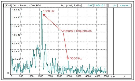
Figure 11.
Natural frequency testing with an impact hammer acceleration (m/s2) versus frequency with two natural frequencies detected.
The vibration results as a function of the frequency of the mains-fed motor and the multilevel inverter are shown below for the SPWM-I, SPWM-II, SPWM-III, and HIPWM–FMTCt techniques. This last technique will only be presented for K = 0.55, for which the vibration level RMS is lowest. The RMS power supply value for all techniques was 220 V RMS. The average frequency of the carrier signals was 750 Hz.
Figure 12 shows the vibrations due to spatial harmonics (tooth harmonics), which are the most significant, as mentioned in Section 2, and which are clearly distinguishable with the sinusoidal power supply. The frequency of the spatial harmonic will be , as Equation (11) shows. With the motor used, the harmonic frequencies of the vibrations produced by these tooth harmonics appear above the values of 18 ± 1 (17,19) and 36 ± 1 (35,37), with p = 2 and s1 = 36. These vibrations will appear in all of the graphs since they are a consequence of the constructive characteristics of the machine. For the 50 Hz power supply, vibrations are identified for 900 Hz and 1800 Hz.
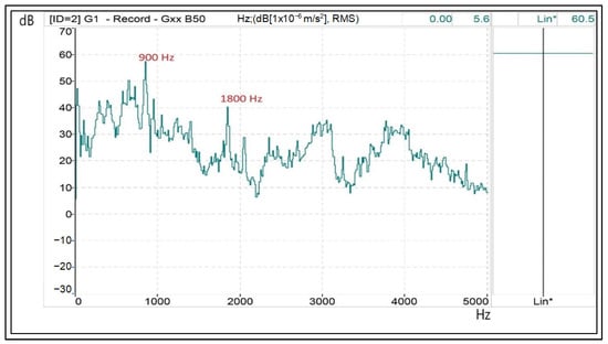
Figure 12.
Tooth harmonics on a spectral vibration diagram—dB/Hz—when the motor is supplied by the three-phase network. (Lin*: measured on a linear scale without weighting adjustment A).
Figure 13 shows the results of the SPWM-I strategy, with M = 15. In addition to the vibrations caused by using a sinusoidal power supply, time harmonics also can be identified. One can observe electrical harmonics 19 (1·750 + 2·50 Hz), 37(2·750 + 7·50 Hz), and 31 (1550 Hz), which activate the natural resonance of 1500 Hz. These electrical harmonics generate vibrational frequencies of 1000 Hz, 1500 Hz, and 1800 Hz, respectively, if the most significant ones are indicated.
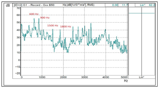
Figure 13.
Mechanical resonances (1500 and 3000 Hz), tooth (900 and 1800 Hz) and electrical harmonics on a spectral vibration diagram—dB/Hz—when the motor is supplied from the multilevel inverter with the SPWM-I technique. (Lin*: measured on a linear scale without weighting adjustment A).
Figure 14 shows the results of the SPWM-II strategy, with M = 15. In addition to the vibrations caused by space harmonics, time harmonics also appeared. It can be observed that electrical harmonics 11, 17, 23, and 29 activate the natural resonance of 1500 Hz. These electrical harmonics generate vibrational frequencies of 600 Hz, 900 (this harmonic coincides with one of harmonic of tooth), 1500 Hz, and 1900 (second-order tooth harmonic).
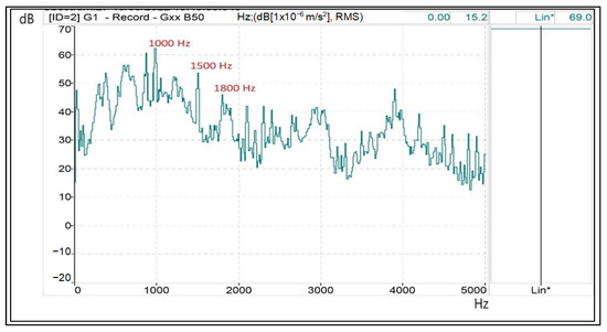
Figure 14.
Mechanical resonances (1500 and 3000 Hz), tooth (900 and 1800 Hz) and electrical harmonics (900 Hz) on a spectral vibration diagram—dB/Hz—when the motor is supplied from a multilevel inverter with the SPWM-II technique. (Lin*: measured on a linear scale without weighting adjustment A).
In Figure 15, we find a vibration spectrum as a function of frequency in the results for the SPWM-III technique that is very similar to the previous one. In addition to the vibrations caused by space harmonics, time harmonics also appeared. It can be observed that electrical harmonics 11, 17, 23, and 29 activate the natural resonance of 1500 Hz. These electrical harmonics generate vibrational frequencies of 600 Hz, 900 (this harmonic coincides with one of harmonic of tooth), 1500 Hz and 1900 (second tooth harmonic).
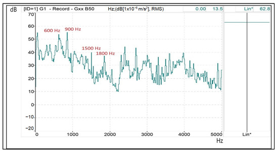
Figure 15.
Mechanical resonances (1500 and 3000 Hz), tooth (900 and 1800 Hz) and electrical harmonics (600 and 900 Hz, mainly) on a spectral vibration diagram—dB/Hz—when the motor is supplied from a multilevel inverter with the SPWM-III technique. (Lin*: measured on a linear scale without weighting adjustment A).
Finally, Figure 16 depicts the results of the proposed HIPWM–FMTCt technique, with K = 0.55 and = 15. It can be seen that vibrations similar to the three previous ones appear, but the vibration is lower, and the natural resonance frequencies of 1500 Hz and 3000 Hz have not been activated due to the adjustment made to parameter K.
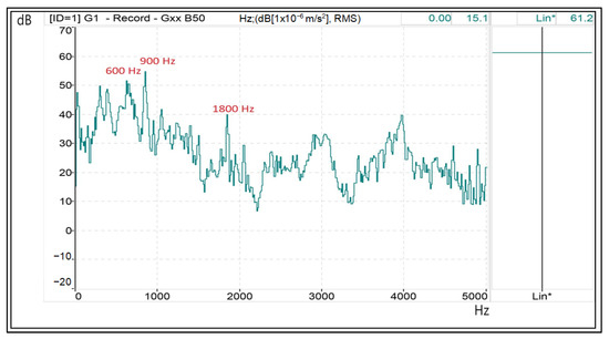
Figure 16.
Tooth harmonics (900 and 1800 Hz) and electrical harmonics (600 and 900 Hz, mainly) on a spectral vibration diagram—dB/Hz—when the motor is supplied from a multilevel inverter with the SPWM-III technique with K = 0.55. (Lin*: measured on a linear scale without weighting adjustment A).
Table 3 shows a summary of the most important results obtained in the laboratory setup. The third column shows the linear value of the accelerometer measurement in dB using 1 × 10⁻⁶ m/s2 as a reference. With the proposed technique and a truncation factor of 0.55, 1 dB less is measured than with the lowest value of the SPWM techniques used for comparison. The RMS line voltage setting at its fundamental term for all of them was 220 V. For that line voltage, the fourth column shows the measured percentage level for the voltage THD. It can be seen that the best value has been obtained by setting the truncation level K to a value of 0.45. Finally, the last column shows how the RMS voltage level at the inverter output can be adjusted by taking the DC-Link voltage at 75 V as a reference.
Table 3.
Experimental Results for = 15 and M = 15.
5. Conclusions
The vibrations produced by an induction machine depend on, among other parameters, the constructive alignments, the electrical harmonics of the power supply, and the degree of saturation of the hysteresis cycle of its magnetic circuit. The use of power inverters to drive them increases the level of vibrations due to the electrical harmonics produced. Among the various sources of vibration production, particularly important are those produced at the natural resonance frequencies of the mechanical structure, which can shorten its useful life. In the present work, a theoretical–practical study of the resonance frequencies of an engine has been described. It has been demonstrated that, by adjusting the control variable of a discontinuous modulation technique, it is possible to avoid the activation of these resonance frequencies, as well as to reduce the vibration level measured with respect to other known techniques (maintaining the frequency modulation order for all the techniques tested). The maximum switching frequencies of the carrier wave for the described technique have also been calculated for two different frequency modulation orders—M = 15 and M = 11—and the results obtained with M = 15 are presented. Measurements were carried out to evaluate both the electrical and vibration results. The main objective of this study was to select values of K that minimize the magnetic harmonic field (MMF) in the air gap, thus reducing the vibrations caused by the motor. If the objective is to reduce the total harmonic distortion (THD) or to increase the root-mean-square (RMS) value of the output voltage, which for the same transferred power will result in a lower current, the most appropriate K value can also be determined. With a K value of 0.55, vibrations are minimized. When K is set to 0.5, there is an improvement in THD, while higher K values cause an increase in RMS values at the inverter output. Within a K range of 0.5 to 0.6, lower vibrations were observed than were with other modulation techniques described in the technical literature. The proposed technique effectively reduces vibrations by not activating mechanical resonances and spatial harmonics with a high winding factor.
Author Contributions
A.R.-G.: conceptualization, methodology, and writing—original draft preparation; F.M.P.-H., J.-R.H.-L. and M.J.M.-G.: simulation and data collection; A.R.-G., F.M.P.-H., J.-R.H.-L. and M.J.M.-G.: hardware implementation, validation, writing—review and editing; F.M.P.-H.: funding acquisition. All authors have read and agreed to the published version of the manuscript.
Funding
This research was funded by National Plan Project ENE-19744C0302, Spain.
Data Availability Statement
The authors confirm that the data supporting the findings of this survey paper are available within the related research papers cited in this article.
Conflicts of Interest
The authors declare no conflict of interest.
References
- Song, P.; Liu, Y.; Liu, T.; Wang, H.; Wang, L. A Novel Suppression Method for Low-Order Harmonics Causing Resonance of Induction Motor. Machines 2022, 10, 1206. [Google Scholar] [CrossRef]
- Liu, H.; Liu, Q.; Zhang, W.; Miao, Y.; Liu, P. Random PWM Technique for Acoustic Noise and Vibration Reduction in Induction Motors used by Electric Vehicles. Trans. China Electrotech. Soc. 2019, 34, 1488–1495. [Google Scholar]
- Devillers, E.; Le Besnerais, J.; Lubin, T.; Hecquet, M.; Lecointe, J. An Improved 2-D Subdomain Model of Squirrel-Cage Induction Machine Including Winding and Slotting Harmonics at Steady State. IEEE Trans. Magn. 2018, 54, 8100612. [Google Scholar] [CrossRef]
- Kocabas, D.A. Novel winding and core design for maximum reduction of harmonic magnetomotive force in AC motors. IEEE Trans. Magn. 2009, 45, 735–746. [Google Scholar] [CrossRef]
- Salem, A.; Van Khang, H.; Robbersmyr, K.G.; Norambuena, M.; Rodriguez, J. Voltage Source Multilevel Inverters with Reduced Device Count: Topological Review and Novel Comparative Factors. IEEE Trans. Power Electron. 2021, 36, 2720–2747. [Google Scholar] [CrossRef]
- Leon, J.I.; Kouro, S.; Franquelo, L.G.; Rodriguez, J.; Wu, B. The Essential Role and the Continuous Evolution of Modulation Techniques for Voltage-Source Inverters in the Past, Present, and Future Power Electronics. IEEE Trans. Ind. Electron. 2016, 63, 2688–2701. [Google Scholar] [CrossRef]
- Yuan, X. Ultimate Generalized Multilevel Converter Topology. IEEE Trans. Power Electron. 2021, 36, 8634–8639. [Google Scholar] [CrossRef]
- Rodriguez, J.; Lai, J.S.; Peng, F.Z. Multilevel inverters: A survey of topologies, controls, and applications. IEEE Trans. Ind. Electron. 2002, 49, 724–738. [Google Scholar] [CrossRef]
- Rodriguez, J.; Bernet, S.; Steimer, P.K.; Lizama, I.E. A survey on neutral-point-clamped inverters. IEEE Trans. Ind. Electron. 2010, 57, 2219–2230. [Google Scholar] [CrossRef]
- Matsui, K.; Kawata, Y.; Ueda, F. Application of parallel connected NPC-PWM inverters with multilevel modulation for AC motor drive. IEEE Trans. Power Electron. 2000, 15, 901–907. [Google Scholar] [CrossRef]
- Huang, J.; Corzine, K.A. Extended operation of flying capacitor multilevel inverters. IEEE Trans. Power Electron. 2006, 21, 140–147. [Google Scholar] [CrossRef]
- Debnath, S.; Qin, J.; Bahrani, B.; Saeedifard, M.; Barbosa, P. Operation, Control, and Applications of the Modular Multilevel Converter: A Review. IEEE Trans. Power Electron. 2015, 30, 37–53. [Google Scholar] [CrossRef]
- Deng, F.; Lü, Y.; Liu, C.; Heng, Q.; Yu, Q.; Zhao, J. Overview on submodule topologies, modeling, modulation, control schemes, fault diagnosis, and tolerant control strategies of modular multilevel converters. Chin. J. Electr. Eng. 2020, 6, 1–21. [Google Scholar] [CrossRef]
- Malinowski, M.; Gopakumar, K.; Rodriguez, J.; Perez, M.A. A survey on cascaded multilevel inverters. IEEE Trans. Ind. Electron. 2010, 57, 2197–2206. [Google Scholar] [CrossRef]
- Corzine, K.A.; Wielebski, M.W.; Peng, F.Z.; Wang, J. Control of cascaded multilevel inverters. IEEE Trans. Power Electron. 2004, 19, 732–738. [Google Scholar] [CrossRef]
- FKhoucha, K.; Lagoun, M.S.; Kheloui, A.; Benbouzid, M.E.H. A Comparison of Symmetrical and Asymmetrical Three-Phase H-Bridge Multilevel Inverter for DTC Induction Motor Drives. IEEE Trans. Energy Convers. 2011, 26, 64–72. [Google Scholar] [CrossRef]
- Yu, Y.; Konstantinou, G.; Hredzak, B.; Agelidis, V.G. Power Balance Optimization of Cascaded H-Bridge Multilevel Converters for Large-Scale Photovoltaic Integration. IEEE Trans. Power Electron. 2016, 31, 1108–1120. [Google Scholar] [CrossRef]
- Tolbert, L.M.; Habetler, T.G. Novel multilevel inverter carrier-based PWM method. IEEE Trans. Ind. Appl. 1999, 35, 1098–1107. [Google Scholar] [CrossRef]
- Yao, W.; Hu, H.; Lu, Z. Comparisons of Space-Vector Modulation and Carrier-Based Modulation of Multilevel Inverter. IEEE Trans. Power Electron. 2008, 23, 45–51. [Google Scholar] [CrossRef]
- Lin, H.; Chen, R.; Li, R.; Zhu, L.; Yan, H.; Shu, Z. A Flexible and Fast Space Vector Pulse Width Modulation Technique for Multilevel Converters. In Proceedings of the 22nd International Conference on Electrical Machines and Systems (ICEMS), Harbin, China, 11–14 August 2019; pp. 1–4. [Google Scholar] [CrossRef]
- Dahidah, M.S.; Konstantinou, G.; Agelidis, V.G. A review of multilevel selective harmonic elimination PWM: Formulations, solving algorithms, implementation and applications. IEEE Trans. Power Electron. 2014, 30, 4091–4106. [Google Scholar] [CrossRef]
- Zolfagharian, O.; Dastfan, A.; Marzebali, M.H. Selective Harmonic Elimination Technique Improvement for Cascaded H-Bridge Multilevel Converters Under DC Sources Uncertainty. IEEE J. Emerg. Sel. Top. Power Electron 2023. [Google Scholar] [CrossRef]
- Darus, R.; Konstantinou, G.; Pou, J.; Ceballos, S.; Agelidis, V.G. Comparison of phase-shifted and level-shifted PWM in the modular multilevel converter. In Proceedings of the 2014 International Power Electronics Conference (IPEC-Hiroshima 2014-ECCE ASIA), Hiroshima, Japan, 18–21 May 2014; pp. 3764–3770. [Google Scholar]
- Subki AS, R.A.; Manap, Z.; Tumari, M.Z.; Jidin, A.Z.; Saat, S.; Abidin, A.F.Z.; Saealal, M.S. Analysis on three phase cascaded H-bridge multilevel inverter based on sinusoidal and third harmonic injected pulse width modulation via level shifted and phase shifted modulation technique. Int. J. Power Electron. Drive Syst. 2021, 12, 160. [Google Scholar]
- Sadegh Orfi, M.; Sarvi, M.; Vlaabjerg, F.; Daravi, P. Improved harmonic injection pulse-with modulation variable frequency triangular carrier scheme for multilevel inverters. IET Power Electron. 2020, 13, 3146–3154. [Google Scholar] [CrossRef]
- Chavarria, J.; Biel, D.; Guinjoan, F.; Meza, C.; Negroni, J.J. Energy-Balance Control of PV Cascaded Multilevel Grid-Connected Inverters Under Level-Shifted and Phase-Shifted PWMs. IEEE Trans. Ind. Electron. 2013, 60, 98–111. [Google Scholar] [CrossRef]
- Ermolaev, A.; Erofeev, V.; Plekhov, A.; Titov, D. Magnetic Vibration in Induction Motor Caused by Supply Voltage Distortion. Energies 2022, 15, 9600. [Google Scholar] [CrossRef]
- Poorfakhraei, A.; Narimani, M.; Emadi, A. A review of modulation and control techniques for multilevel inverters in traction applications. IEEE Access 2021, 9, 24187–24204. [Google Scholar] [CrossRef]
- Seshadri, A.; Lenin, N.C. Review based on losses, torque ripple, vibration and noise in switched reluctance motor. IET Electr. Power Appl. 2020, 14, 1311–1326. [Google Scholar] [CrossRef]
- Gieras, J.F.; Wang, C.; Cho Lay, J. Inverter-Fed Motors in Noise of Poliphase Electric Motors; CRC Press, Taylor&Francis Group: Boca Raton, FL, USA, 2006. [Google Scholar]
- Meco-Gutierrez, M.J.; Perez-Hidalgo, F.; Vargas-Merino, F.; Heredia-Larrubia, J.R. A New PWM Technique Frequency Regulated Carrier for Induction Motors Supply. IEEE Trans. Ind. Electron. 2006, 53, 1750–1754. [Google Scholar] [CrossRef]
- Ruiz-Gonzalez, A.; Meco-Gutierrez, M.J.; Vargas-Merino, F.; Heredia-Larrubia, J.R.; Perez-Hidalgo, F. Pulse width modulation technique with harmonic injection in the modulating wave and discontinuous frequency modulation for the carrier wave to reduce vibrations in asynchronous machines. IET Power Electron. 2019, 12, 2865–2872. [Google Scholar] [CrossRef]
- Ruiz-Gonzalez, A.; Heredia-Larrubia, J.R.; Meco-Gutierrez, M.J.; Perez-Hidalgo, F.M. Pulse-Width Modulation Technique with Harmonic Injection in the Modulating Wave and Discontinuous Frequency Modulation for the Carrier Wave for Multilevel Inverters: An Application to the Reduction of Acoustic Noise in Induction Motors. IIEEE Access 2023, 11, 40579–40590. [Google Scholar] [CrossRef]
- Yegane, M.S.O.; Sarvi, M. An improved harmonic injection PWM-frequency modulated triangular carrier method with multiobjective optimizations for inverters. Electr. Power Syst. Res. 2018, 160, 372–380. [Google Scholar] [CrossRef]


Disclaimer/Publisher’s Note: The statements, opinions and data contained in all publications are solely those of the individual author(s) and contributor(s) and not of MDPI and/or the editor(s). MDPI and/or the editor(s) disclaim responsibility for any injury to people or property resulting from any ideas, methods, instructions or products referred to in the content. |
© 2023 by the authors. Licensee MDPI, Basel, Switzerland. This article is an open access article distributed under the terms and conditions of the Creative Commons Attribution (CC BY) license (https://creativecommons.org/licenses/by/4.0/).