Abstract
The core design elements of the motor for the co-robot joint are miniaturization and high torque. In this paper, a dual rotor axial-flux permanent magnet (DRAFPM) motor is proposed to improve the performance of robot joints. DRAFPM motors have the advantage of reducing iron loss and minimizing volume because they can remove stator yoke. When designing a motor with the same volume, it can be designed to increase the height of the fixed ruler by the thickness of the yoke of the fixed ruler and increase the number of turns. In the case of existing axial-flux permanent magnet (AFPM) motors, the shape of the three-dimensional structure is limited by radial laminating of stator. Therefore, considering the production of 3D printing, the shape of stator shoe is designed. The optimal design problem of DRAFPM motor consists of real and integer design variables. In addition, due to the structural characteristics of DRAFPM motors, 3D finite element analysis (FEA) is required, so it takes a long time to interpret. Therefore, this paper proposes an efficient optimal design process to optimize the remaining real design variables after prioritizing the integer design variables. The proposed optimization process is applied to the DRAFPM motor for robot joints, and the optimal design plan satisfying the design function is derived from various design variables to prove the validity of the optimization process.
1. Introduction
Recently, the robot market is making rapid progress as the fourth industrial revolution technologies, such as artificial intelligence, big data, and 5G combine with robots. As shown in Figure 1, the global robot market is around $30.5 billion in 2019. It will grow at an average annual rate of 32% by 2025. It is projected to grow to $17.2 billion by 2025 [1,2,3,4,5].
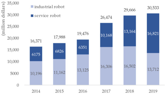
Figure 1.
The growth prospects of the global robot market.
Although the service robot market is rapidly emerging mainly in the logistics sector, the industrial robot market is still growing. The annual number of industrial robots installed in Figure 2 is 384,000 units, up 0.5% from the previous year. A new variable in the industrial robot market is collaborative robot. Collaborative robots are smaller and lighter than conventional industrial robots so that they can be installed beside human workers without additional equipment.
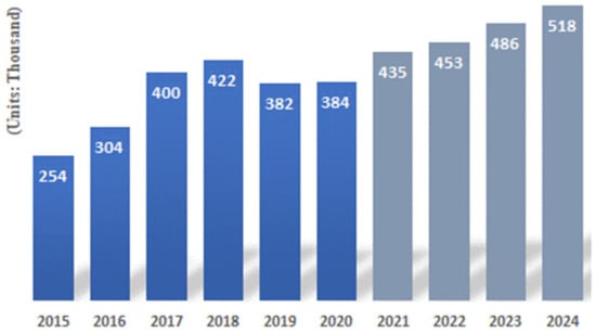
Figure 2.
Number of annual installations of industrial robots.
The motor, one of the core components of the collaborative robot, is very closely related to the speed, repetition accuracy, range of motion, maximum torque, etc., which represent the robot’s athletic ability. Therefore, motors used in collaborative robot joints design elements of miniaturization, high torque, and high control performance [6,7,8]. The axial flux permanent magnet (AFPM) motor proposed in this paper has a higher torque density than the radial flux permanent magnet (RFPM) motor. The AFPM motor is advantageous for torque density, power density, high efficiency, and miniaturization compared to RFPM motor with the same volume and weight [9,10,11,12,13,14].
Figure 3 shows the shape and name of the RFPM motor and the AFPM motor [15].
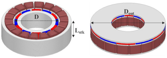
Figure 3.
Shape and name of RFPM and AFPM motor.
The torque of the RFPM motor is proportional to the square of the motor diameter, as shown in Equation (1). In here, is specific electric loading, is winding coefficient, and is a fundamental of airgap magnetic flux density.
The torque of the AFPM motor is proportional to the cube of the motor diameter, as shown in Equation (2). As the AFPM motor can increase the permanent magnet usage at the same volume, it has high torque and high efficiency characteristics compared to the RFPM motor [16,17,18,19,20].
For motor for robot joints, the axial length must be short. This is because it is made into one module per joint. In this paper, an AFPM motor is applied to motors for robot joints that require high torque characteristics at a limited volume. It was designed with dual rotor AFPM (DRAFPM) motor to further enhance the output.
In the case of the DRAFPM motor, the stator back-yoke can be removed by structural features. Consequently, core loss can also be reduced. The thickness of the rotor back-yoke, magnet, stator shoe and teeth, etc., can be changed by the thickness of the removed stator back-yoke. Therefore, many design variables must be considered. In the process, the number of turns can also be changed. As a result, design variables consist of integers and real numbers. The motor’s characteristic analysis generally uses finite element analysis (FEA). In the case of the existing RFPM motor, relatively accurate performance can be predicted only with two-dimensional analysis. However, in the case of the DRAFPM motor, a three-dimensional analysis is structurally required. In the case of 3D analysis, it takes longer to interpret compared to 2D analysis. An efficient optimal design process is needed for the design of the DRAFPM motor.
In this paper, a sequential optimization (SAO) technique based on an efficient progressive meta model was applied to the DRAFPM motor. In addition, the design of experiment-based effect analysis technique was introduced to propose a process for preferentially optimizing integer design variables.
The proposed process is summarized as follows. Step 1 builds a model for advancing the optimum design is constructed. Step 2, the effect analysis method is applied to prioritize optimization of integer design variables. Step 3, the integer design variable is fixed to constant, then the remaining real number design variables are optimized based on the progressive meta-model.
This paper consists of a total of six sections. Section 1 discusses the background and necessity of the study. Section 2 examines the characteristics of the motor for robot joints and explains the characteristics of the AFPM motor. Additionally, we will examine the various topologies of the AFPM motor and briefly describe the characteristics of the DRAFPM motor. Section 3 designs AFPM motors based on target RFPM motor specifications. Section 4 applies the effect analysis technique, optimizes the integer design variables preferentially, then optimizes the remaining real number design variables based on the progressive meta model. Section 5 utilizes the proposed process to advance the optimal design of the DRAFPM motor for robot joints. Section 6 summarizes the conclusions of this paper.
2. Robot Joint Motor and Axial Flux Permanent Magnet Synchronous Motor
2.1. Motor Characteristics for Robot Joints
Figure 4 shows the components of the joint robot and the drive module. Currently, RFPM motor for robot joints is mainly used as shown in Figure 5. The motor size has been reduced to a smaller size, and SPMSM’s performance has reached its limit. Therefore, it is necessary to study the high torque of motor for robot joints.
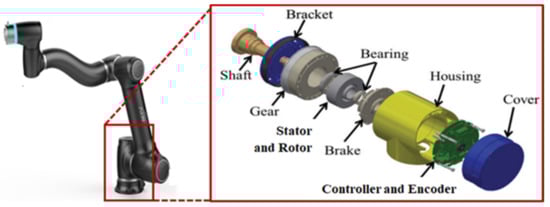
Figure 4.
Joint robot and drive module components.
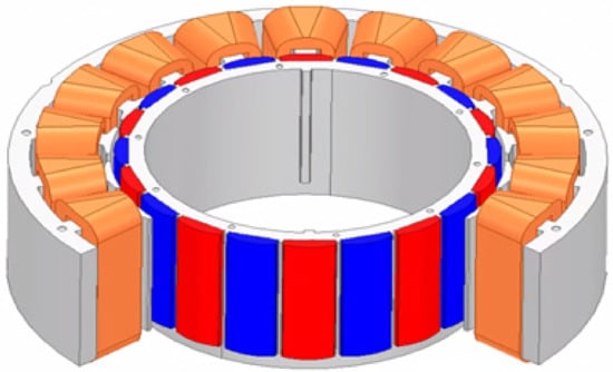
Figure 5.
Surface-mounted permanent magnet synchronous motor.
2.2. Axial Flux Permanent Magnet Motor Characteristics
The AFPM motor shape is shown in Figure 6. The AFPM motor is thin and proportional to the cubic diameter. Therefore, the AFPM motor can effectively generate torque [21,22,23,24]. The shorter the axial length of the motor for robot joints, the better. The AFPM motor is suitable for the motor for robot joints because it has a very short axial length compared to the radial direction. The AFPM motor can be designed in various topologies as shown in Figure 7 depending on the configuration of the rotor and stator, and the permanent magnet arrangement [25].
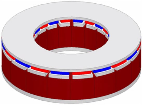
Figure 6.
Axial flux permanent magnet synchronous motor shape.
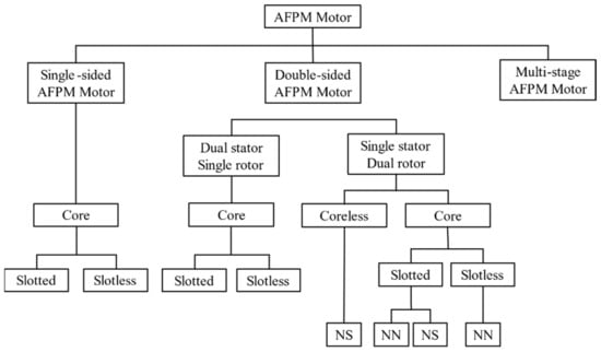
Figure 7.
Topology of AFPM motors.
In this paper, the dual rotor structure was applied to the single stator to enhance the occurrence of torque.
Among them, the NS type rotor has a structure in which the permanent magnetization direction of the two-sided rotor is opposite. One rotor permanent magnet magnetic flux flow to the opposite rotor. The advantage is that there is no magnetic flux flowing through the Stator back-yoke, making the design easier. Furthermore, by removing the stator back-yoke, manufacturing can be performed in a split core structure, and the fill factor can be enhanced [26,27,28,29,30].
3. Dual Rotor Axial Flux Permanent Magnet Synchronous Motor Design
3.1. Target RFPM Synchronous Motor
In this paper, 500 W SPMSM was selected as the target motor among the motors for robot joints. Figure 8a,b show the shape of the target RFPM motor. Table 1 shows the specifications of the target RFPM motor.
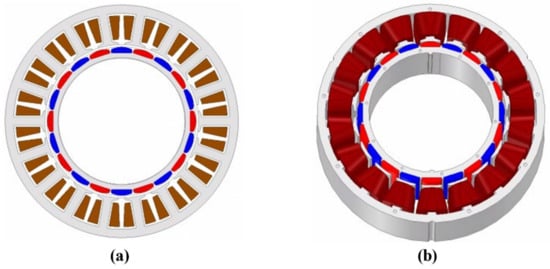
Figure 8.
(a). 2D shape of target RFPM motor; (b) 3D shape of target RFPM motor.

Table 1.
Target RFPM motor specification.
The motor’s back electromotive force (BEMF) and total harmonic distortion (THD) can be identified through a no-load analysis. As the THD decreases, the vibration noise of the motor decreases. The no-load analysis is based on 1000 rpm. Figure 9 shows the BEMF waveform of the target RFPM motor.
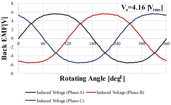
Figure 9.
Back EMF FEA result of target RFPM motor @1000 rpm.
The THD of the target RFPM motor obtained from Figure 9 is 5.51%. The smaller the THD, the more sinusoidal the waveform is. As the waveform is sinusoidal, the heat, vibration, and core loss of the motor are reduced and performance is improved.
3.2. AFPM Motor Design
Figure 10a,b shows the shape of the target RFPM motor and the shape of the AFPM motor. The slot area is the area for obtaining the fill factor. The slot areas of the two motors are the same.
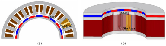
Figure 10.
(a) Shape of target RFPM motor fill factor area. (b) AFPM motor fill factor area.
In the same way as the RFPM motor, no-load analysis was performed based on 1000 rpm. Figure 11 shows the BEMF waveform of the AFPM motor. The voltage is 4.21 and 6.16% for THD.

Figure 11.
Back EMF FEA result for AFPM motor @1000 rpm.
3.3. Dual Rotor Type AFPM Synchronous Motor Design
The DRAFPM motor has rotors on both sides so that the stator back-yoke can be removed. The advantage is that removing the Stator back-yoke can reduce the size of the motor. In this paper, while having the same volume, the height of the stator teeth was increased to further wind up the number of turns.
The DRAFPM motor was designed as a dual rotor by dividing the thickness of the AFPM motor rotor back-yoke and magnet in half. Accordingly, the same permanent magnet usage is used. Figure 12 shows the DRAFPM motor with the same 20 pole 18 slot as the target RFPM motor. To check the performance according to the combination of pole and slot numbers together, the optimal design was carried out in Section 4 by adding a 24 pole 18 slot model.
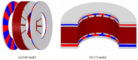
Figure 12.
Shape of DRAFPM motor.
4. Optimal Design Process with Mixed Variables (Integer and Real Number)
4.1. Sequential Approximate Optimization Techniques Based on Progressive Meta-Model
The optimization based on progressive meta-model constructs the initial meta-model with a minimum number of experimental points. After that, the meta-model is upgraded by adding experimental points that approximate the optimization conditions one by one. The optimization-based on progressive meta model differs from the existing optimization-based on meta model when repeatedly generating meta models repeatedly. Instead of adding multiple experimental points repeatedly, only new approximate optimal solutions are added to the existing experimental points. Accordingly, an approximate optimal solution is newly added to an existing experimental point to narrow the region where the solution exists.
The progressive meta model-based optimal design process is shown in Figure 13. We planned the experiment with minimal experimental points for the initial meta-model configuration. After that, a constraint condition for the performance index and an optimization condition for the objective function are defined. After that, an experiment for meta-model generation is performed to configure the meta-model and a predicted value for the Sequential approximate optimization (SAO) is calculated. The propriety of convergence by an optimization Equation and a restriction condition is determined. If it does not converge, the functional expression of the meta model is changed according to the position of the approximate solution in consideration of the convergence of SAO. Accordingly, a meta model can be created by adding approximate optimal solutions one by one. This is much more efficient than the optimization method based on the existing meta-model.
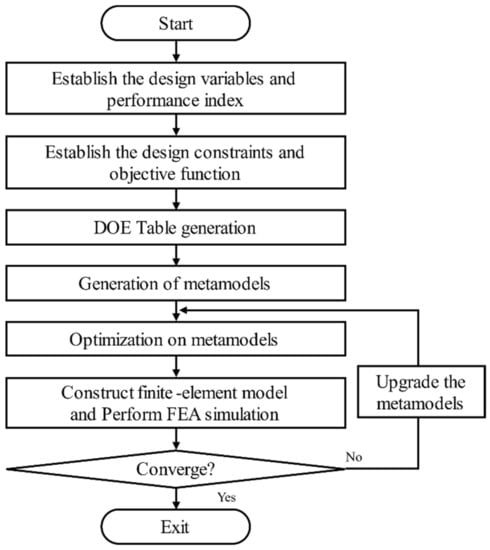
Figure 13.
Sequential approximate optimization process based on progressive meta model.
The progressive meta model based optimal design is efficient but can only be applied to a single type of design variable (real or integer). Therefore, a new optimal design process was proposed in Section 4.2 to apply it to models with a mixture of integer and real number variables.
4.2. Optimal Design Process with Mixed Variables (Integer and Real Number)
An electric motor cannot constitute a finite element model when the number of turns is optimized to a real number. In particular, the DRAFPM motor is a composite model consisting of many real number design variables and integer design variables.
Accordingly, a process for optimizing the real number type design variable based on the progressive meta model is proposed after preferentially determining the optimization candidate of the integer type variable. An optimum design process having an integer type design variable is shown in Figure 14.
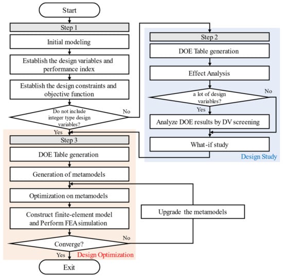
Figure 14.
An optimum design process having an integer type design variable.
In the first stage, a model for advancing the optimum design is constructed. In step 2, an integer type design variable can be preferentially optimized by the Effect Analysis method of the Design of Experiment. As the effect analysis method has discrete experimental points, it is difficult to apply to motor designs that require finite element analysis results, which are continuous functions. However, if the influence of the integer type design variable is determined and used as a method to reduce the range of the integer type design variable, the optimum design can be very efficient. This is because all mixed design variables (integer and real number) can be considered.
Except for integer type design variables, the optimal model may not be found even if the optimal design is advanced several times or even dozens of times. An integer type design variable whose range is narrowed in step 2 is fixed with a constant value and moved to step 3.
In step 3, we will proceed with the optimal design based on progressive meta model. In Section 5, the proposed Optimal design process with mixed variables was applied to the DRAFPM motor.
5. Optimal Design of Dual Rotor AFPM Motor
5.1. Constructing an Optimal Design Model
Figure 15 shows the design variables for the 24 pole 18 slot DRAFPM motor. The design variables of the 20 pole 18 slot model are the same. There are a total of eight design variables, including seven real number design variables and an integer design variable (number of turns), shown in Figure 15.
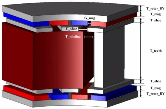
Figure 15.
Design variables of the DRAFPM motor.
The design variables and design areas set in Table 2 are shown. The design area was set based on the DRAFPM motor designed in Section 3.3. The design area of each design variable was set so that the finite element models did not collide with each other. Based on the number of turns of the target RFPM motor, 9 turns, the stator back-yoke is removed, and the number of turns due to the increased slot area, 12 turns, is limited to the upper limit. Accordingly, 9–12 turns is the range of integer type design variables (number of turns). For the remaining real number type design variables, the range of the upper and lower limit values was divided into four. Here, DV was used as an abbreviation for design variable.
Table 2.
Design variables and design areas for DRAFPM motor.
The DRAFPM motor aims to maximize torque at the same volume as the target RFPM motor. Therefore, four performance indices were compared: no-load BEMF and THD, height of the stator teeth, and fill factor. The four performance indices are shown in Table 3. In the case of no-load BEMF, the goal of performance improvement was selected as maximization because it is closely related to torque. THD was selected as an upper limit constraint to have a value less than 5.51%, which is the THD value of the target RFPM motor. As it is designed in the same volume as the target RFPM motor, the target is 28 mm for the height of the stator teeth and 40% for the fill factor.
Table 3.
Objectives and limitations of DRAFPM motor design variables.
The design problem of the DRAFPM motor is defined as shown in Equation (3).
A no-load BEMF () is a maximization condition. A THD () is made smaller than a target motor (), and a height of the stator teeth () and a fill factor () are the same condition as a target RFPM motor (, ).
5.2. Primary Optimization of Integer Design Variables with Design of Experiment-Based Effect Analysis
Table 4 shows the design of experiment (DOE) worksheet for the DRAFPM motor. In this design problem, 12 experimental points of 4 levels were designed. Since the number of experiments is more than the number of design variables and should be a multiple of the number of levels, experimental points were set to 12. Both 20 pole 18 slots and 24 pole 18 slots have the same design variable and performance index. Therefore, use the same DOE worksheet.
Table 4.
DOE worksheet of DRAFPM motor.
Once the DOE worksheet is completed, a finite element model with a total of 12 experimental points is constructed and a finite element analysis is performed. The effects on each design variable were then analyzed. The 20 pole 18 slot and 24 pole 18 slot experiment schedules are the same, but the finite element analysis must be carried out separately.
Effect analysis techniques analyze the influence of design variables on performance. The larger the design variable, the more variable the performance tends to change. In this design problem, we applied it to analyze the influence of the number of turns, which is an integer type design variable.
Figure 16 shows the effect analysis results of the 20 pole 18 slot model according to four performance indices. Figure 17 shows the effect analysis results of 24 poles and 18 slots. This shows the effect of each design variable by level.
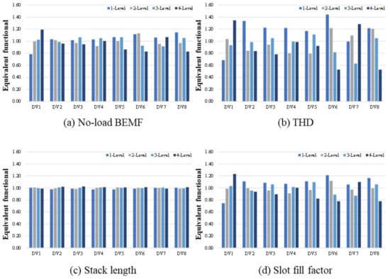
Figure 16.
Effect analysis results (20P 18S).
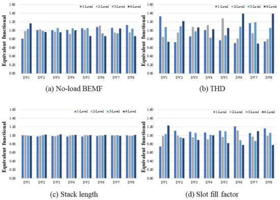
Figure 17.
Effect analysis results (24P 18S).
According to the effect analysis results shown in Figure 16, the magnitude of the no-load counter electromotive force and fill factor tend to increase as the number of turns (DV1) increases. Compared with the no-load counter electromotive force Equation (4), the result is reasonable because it is proportional to the number of turns, where is the induced voltage, is the total Flux linkage of the coil, is the number of turns, and is the average flux linkage per winding.
The biggest difference between the 20 pole 18 slot and the 24 pole 18 slot is as follows. In the 20 pole 18 slot, the THD decreased with increasing winding thickness (DV6) and shoe spacing (DV8). On the contrary, 24 pole 18 slots showed a tendency for THD to increase as the window thickness (DV6) and shoe spacing (DV8) increased.
THD is the total harmonic content. A lower THD means that the waveform of the Back electromotive force is closer to the sinusoidal wave. Accordingly, the THD value varies greatly depending on the value of the design variable affecting the rotor and the stator magnetic flux. The height of the stator teeth is less influenced by the level-specific design variables. The reason for this is that Section 5.1 has set the design area of each design variable to an appropriate range to produce the same volume.
Figure 18 shows the mean value chart by virtual design. The mean value chart indicates that the lowest value is the result closest to the design goal. Accordingly, 10 turns and 11 turns, which are low values in the number of integer type design variable (DV1, turns), are optimal candidates for the 20 pole 18 slot. The 24 pole 18 slot is 11 turns and 12 turns, respectively. In fact, we proceeded with the finite element analysis of the 20 pole 18 slot 12 turns model. It was confirmed that core saturation tends to increase, and performance tends to decrease. Accordingly, step 3 is a 20 pole 18 slot (10 turns, 11 turns) and a 24 pole 18 slot (11 turns, 12 turns) model, and the optimum design is advanced for a total of four types.
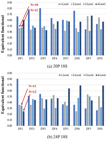
Figure 18.
What-if design mean value chart.
The constraint function and the objective function of Equation (3) are taken to generate the meta model from the DOE worksheet created in Step 2. At this time, the integer type design variables (DV1, turns) determined in step 2 are fixed by constant. After that, the optimum design for the remaining seven real number design variables is advanced. The 4 models are 20 pole 18 slots (10 turns and 11 turns, respectively) and 24 pole 18 slots (11 turns and 12 turns, respectively).
Figure 19 shows the performance index convergence history of the four models. As a result of using the sequential optimization process based on progressive meta model, convergence was confirmed through up to seven iterative optimization processes (calculating the optimization results of the meta model; constructing and interpreting the finite element model; verifying convergence; if not converged, reconfiguring the meta model and repeated calculating the optimization results).
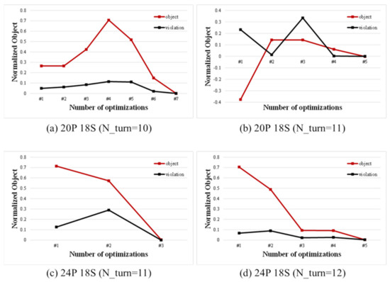
Figure 19.
Convergence history.
5.3. Final Model Selection and Performance Comparison
Figure 20 shows the no-load BEMF FEA results for the four models. Table 5 shows four performance index results including no-load BEMF results.
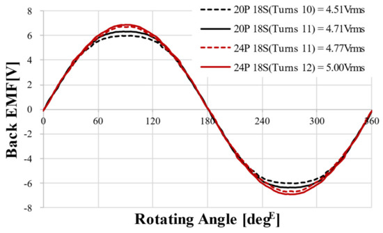
Figure 20.
Back EMF FEA results of optimization model @1000 rpm.
Table 5.
Optimal Design Results.
All four designs satisfied the constraints and objective functions. Therefore, considering that the design objective of the no-load BEMF is maximization, the 24 pole 18 slot 12 turns model was selected as the final model.
The design variable optimization results of the final selected 24 pole 18 slot 12 turn model are shown in Table 6. Figure 21 shows the final design shape of the DRAFPM motor compared to the target RFPM motor. Compared to the target RFPM motor, the no-load BEMF increased by 20.19%, and the THD decreased by 69.69%. At load, torque was increased by 21.92%. Figure 22 shows the torque waveform of the final DRPMSM motor and the magnetic flux density at load.
Table 6.
Final Model Design Variable of Optimization Results.
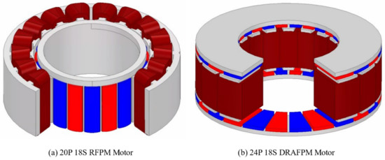
Figure 21.
Shape of final DRAFPM motor and target RFPM motor model.
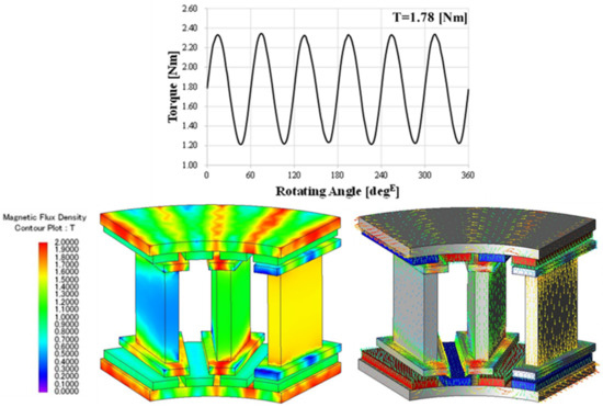
Figure 22.
Torque waveform of the final DRAFPM motor and magnetic flux density distribution at load.
6. Conclusions
Amid the rapid progress of the robot market, interest in cooperative robots that can collaborate with humans is increasing. Therefore, in this paper, an axial magnetic flux permanent magnet synchronous motor having both-sided rotor structure is applied. This can increase the torque density of the motor for cooperative robot joints.
In the DRAFPM motor designed in this paper, the magnetic flux of a permanent magnet forms NS (N pole-S pole) on both sides. A magnetic flux emitted from the N pole of one rotor permanent magnet flows to the S pole of the opposite rotor permanent magnet to constitute a closed circuit. Furthermore, since there is no magnetic flux flowing in the stator yoke, the stator yoke can be removed. This is suitable for motor for robot joints requiring miniaturization, high torque, and high efficiency characteristics. In this paper, the DRAFPM was designed to improve output while having the same volume as target motor. As the stator yoke is removed, the remaining design variables can be changed and performance can be improved.
In the design problem of the DRAFPM motor, the winding can be wound more by removing the stator yoke, and the number of turns (integer type) is also a design variable. In addition, 3D FEA is required for the DRAFPM motor due to its structural characteristics. This will soon cost an enormous amount of time and money to interpret. Therefore, this paper proposes an efficient optimal design process with mixed variables (integer and real number). You can quickly and accurately find excellent solutions for DRAFPM motors with mixed variables (integer and real number).
It is difficult to apply the explicit relationship between the design variables (input variables) and the performance index (output response) to the DRAFPM motor when proceeding with the optimal design. Therefore, the relationship must be established through finite element analysis. However, in the case of the number of turns, since it is an integer type design variable, a finite element model cannot be constructed if it is optimized to a real number type. Therefore, the following optimal design processes are proposed in this paper. An integer type design variable (number of turns) is preferentially optimized. After that, the optimization candidate is fixed with a constant, then the optimum design is advanced for the remaining real number type design variables.
A DRAPFM motor was designed, and polar number slot number models were selected. The optimal design was carried out by applying the proposed optimal design process.
Finally, four motor models were subjected to finite element analysis. As a result, all four models satisfied the design function. This result confirms that the proposed optimal design process can find excellent solutions considering both integer and real number design variables. As all the design functions were satisfied, the model with the highest performance was selected as the final model according to the maximization goal of performance improvement.
To determine the suitability of the optimally designed DRAFPM motor for robot joints, we compared it with the RFPM motor. The validity was verified by obtaining high performance based on the results of no-load and load analysis. It is judged that the DRAFPM motor proposed in this paper can be applied not only in the motor for robot joints, but also in the field of applications requiring miniaturization and high performance.
Author Contributions
Conceptualization, W.-H.K.; methodology, S.-H.Y.; software, S.-H.Y.; validation, S.-H.Y.; formal analysis, H.-J.P.; investigation, H.-J.P.; resources, S.-H.Y.; data curation, S.-H.Y.; writing—original draft preparation, S.-H.Y.; writing—review and editing, H.-J.P. and D.-H.J.; visualization, S.-H.Y. and D.-H.J.; supervision, W.-H.K. All authors have read and agreed to the published version of the manuscript.
Funding
This research was supported by a grant of the Basic Research Program funded by the Korea Institute of Machinery and Materials (grant number: NK242J), and in part by the Gachon University research fund of 2019 (No. 2019-0770).
Data Availability Statement
Not applicable.
Conflicts of Interest
The authors declare no conflict of interest.
References
- Wu, S.-H.; Hong, X.-S. Integrating Computer Vision and Natural Language Instruction for Collaborative Robot Human-Robot Interaction. In Proceedings of the 2020 International Automatic Control Conference (CACS), Hsinchu, Taiwan, 4–7 November 2020; pp. 1–5. [Google Scholar]
- Shin, D.-Y.; Jung, M.-J.; Lee, K.-B.; Lee, K.-D.; Kim, W.-H. A Study on the Improvement of Torque Density of an Axial Slot-Less Flux Permanent Magnet Synchronous Motor for Collaborative Robot. Energies 2022, 15, 3464. [Google Scholar] [CrossRef]
- Liu, L.; Guo, F.; Zou, Z.; Duffy, V.G. Application, development and future opportunities of collaborative robots (cobots) in manufacturing: A literature review. Int. J. Hum. Comput. Interact. 2022, 1–18. [Google Scholar] [CrossRef]
- Hentout, A.; Aouache, M.; Maoudj, A.; Akli, I. Human–robot interaction in industrial collaborative robotics: A literature review of the decade 2008–2017. Adv. Robot. 2019, 33, 764–799. [Google Scholar] [CrossRef]
- Sherwani, F.; Asad, M.M.; Ibrahim, B.S.K.K. Collaborative robots and industrial revolution 4.0 (ir 4.0). In Proceedings of the 2020 International Conference on Emerging Trends in Smart Technologies (ICETST), Karachi, Pakistan, 26–27 March 2020; pp. 1–5. [Google Scholar]
- Haddadin, S.; Albu-Schäffer, A.; Hirzinger, G. Safe Physical Human-Robot Interaction: Measurements, Analysis and New Insights. In Proceedings of the 13th International Symposium of Robotics Research (ISRR2007), Hiroshima, Japan, 26–29 November 2007. [Google Scholar]
- Veronneau, C.; Denis, J.; Lhommeau, P.; St-Jean, A.; Girard, A.; Plante, J.-S.; Bigue, J.-P.L. Modular Magnetorheological Actuator with High Torque Density and Transparency for the Collaborative Robot Industry. IEEE Robot. Autom. Lett. 2022, 8, 896–903. [Google Scholar] [CrossRef]
- Duong, M.-T.; Luu, T.-P.; Do, T.D.; Perriard, Y. Design of High Torque Density Permanent Magnet Motors and Drives for Collaborative Robot Applications. In Proceedings of the 2021 24th International Conference on Electrical Machines and Systems (ICEMS), Gyeongju, Republic of Korea, 31 October–3 November 2021. [Google Scholar]
- Chen, Y.; Pillay, P.; Khan, A. PM Wind Generator Topologies. IEEE Trans. Ind. Appl. 2005, 41, 1619–1626. [Google Scholar] [CrossRef]
- Profumo, F.; Shang, Z.; Tenconi, A. Axial Flux Machines Drives; A New Viable Solution for Electric Cars. IEEE Trans. Ind. Electron. 1997, 44, 39–54. [Google Scholar] [CrossRef]
- Messina, G.; Tamburo, E.; Bella, D.; Morici, L. HTS Axial Flux Permanent Magnets Electrical Machine Prototype: Design and Test Results. IEEE Trans. Appl. Supercond. 2019, 29, 5. [Google Scholar] [CrossRef]
- Alvarez, A.; Suarez, P.; Caceres, D.; Cordero, E.; Ceballos, J.-M.; Perez, B. Disk-shaped Superconducting rotor under a rotating magnetic field: Speed dependence. IEEE Trans. Appl. Supercond. 2005, 15, 2. [Google Scholar] [CrossRef]
- Pippuri, J.; Manninen, A.; Keranen, J.; Tammi, K. Torque density of radial, axial and transverse flux permanent magnet machine topologies. IEEE Trans. Magn. 2013, 49, 2339–2342. [Google Scholar] [CrossRef]
- Qu, R.; Aydin, M.; Lipo, T.A. Performance comparison of dual-rotor radial-flux and axial-flux permanent-magnet BLDC machines. In Proceedings of the IEEE International Electric Machines and Drives Conference, Madison, WN, USA, 1–4 June 2003; pp. 1948–1954. [Google Scholar]
- González-Paradaa, A.; Guía, M.; Ibarraa, O. Development of axial flux HTS induction motors. Int. Meet. Electr. Eng. Res. 2012, 35, 4–13. [Google Scholar] [CrossRef]
- Gieras, J.F.; Wang, R.J.; Kamper, M.J. Axial Flux Permanent Magnet Brushless Machines; Springer: Cham, Switzerland, 2008. [Google Scholar]
- Pyo, H.-J.; Lee, K.; Min, J.-Y.; Hong, M.-K.; Kim, W.-H. Eddy Current Loss Reduction in Axial-Flux Motors Using 3D Printing. Energies 2023, 16, 1318. [Google Scholar] [CrossRef]
- Aydin, M.; Huang, S.; Lipo, T.A. Torque quality and comparison of internal and external rotor axial flux surface-magnet disc machines. IEEE Trans. Ind. Electron. 2006, 53, 822–830. [Google Scholar] [CrossRef]
- Bi, Y.; Pei, Y.; Chai, F. A novel axial flux interior permanent magnet motor with high torque density. In Proceedings of the 2019 22nd International Conference on Electrical Machines and Systems (ICEMS), Harbin, China, 11–14 August 2019; pp. 1–5. [Google Scholar]
- Aydin, M.; Gulec, M. A new coreless axial flux interior permanent magnet synchronous motor with sinusoidal rotor segments. IEEE Trans. Magn. 2016, 52, 1–4. [Google Scholar] [CrossRef]
- Rahim, N.A.; Ping, H.W.; Tadjuddin, M. Design of axial flux permanent magnet brushless DC motor for direct drive of electric vehicle. In Proceedings of the IEEE General Meeting Power & Energy Society, Tampa, FL, USA, 24–28 June 2007; pp. 1–6. [Google Scholar]
- Caricchi, F.; Capponi, F.G.; Crescimbini, F.; Solero, L. Experimental study on reducing cogging torque and no-load power loss in axial-flux permanent-magnet machines with slotted winding. IEEE Trans. Ind. Appl. 2004, 40, 1066–1075. [Google Scholar] [CrossRef]
- Watanabe, A.; Saito, T.; Ueno, T.; Tsuruta, H.; Nakamura, Y. Thin and High-Torque Axial Gap Motor Using Soft Magnetic Powder Cores. SEI Tech. Rev. 2018, 86, 106–112. [Google Scholar]
- Cavagnino, A.; Lazzari, M.; Profumo, F.; Tenconi, A. A comparison between the axial flux and the radial flux structures for PM synchronous motors. IEEE Trans. Ind. Appl. 2002, 38, 1517–1524. [Google Scholar] [CrossRef]
- Capponi, F.G.; De Donato, G.; Caricchi, F. Recent advances in axial-flux permanent-magnet machine technology. IEEE Trans. Ind. Appl. 2012, 48, 2190–2205. [Google Scholar] [CrossRef]
- Hemeida, A.; Taha, M.; Abdallh, A.A.E.; Vansompel, H.; Dupré, L.; Sergeant, P. Applicability of Fractional Slot Axial Flux Permanent Magnet Synchronous Machines in the Field Weakening Region. IEEE Trans. Energy Convers. 2017, 32, 111–121. [Google Scholar] [CrossRef]
- Zhang, B.; Andreas, S.; Doppelbauer, M. Development of a novel yokeless and segmented armature axial flux machine based on soft magnetic powder composites. In Proceedings of the World PM 2016 Congress and Exhibition, Hamburg, Germany, 9–13 October 2016; Volume 63, pp. 2062–2071. [Google Scholar]
- Arand, S.J.; Ardebili, M. Multi-objective design and prototyping of a low cogging torque axial-flux PM generator with segmented stator for small-scale direct-drive wind turbines. IET Electr. Power Appl. 2016, 10, 889–899. [Google Scholar] [CrossRef]
- Woolmer, T.J.; McCulloch, M.D. Axial flux permanent magnet machines: A new topology for high performance applications. In Proceedings of the IET Hybrid Vehicle Conference, Coventry, UK, 12–13 December 2006; Volume 2006, pp. 27–42. [Google Scholar]
- Paiva, R.D.; Silva, V.C.; Nabeta, S.I.; Chabu, I.E. Magnetic topology with axial flux concentration: A technique to improve permanent-magnet motor performance. J. Microw. Optoelectron. Electromagn. Appl. 2017, 16, 881–899. [Google Scholar] [CrossRef]


Disclaimer/Publisher’s Note: The statements, opinions and data contained in all publications are solely those of the individual author(s) and contributor(s) and not of MDPI and/or the editor(s). MDPI and/or the editor(s) disclaim responsibility for any injury to people or property resulting from any ideas, methods, instructions or products referred to in the content. |
© 2023 by the authors. Licensee MDPI, Basel, Switzerland. This article is an open access article distributed under the terms and conditions of the Creative Commons Attribution (CC BY) license (https://creativecommons.org/licenses/by/4.0/).