Article

Design and Implementation of Hardware-in-the-Loop Simulation Environment Using System Identification Method for Independent Rear Wheel Steering System

Platform Safety Technology R&D Department, Korea Automotive Technology Institute, Chungnam 31214, Republic of Korea
Machines 2023, 11(11), 996; https://doi.org/10.3390/machines11110996
Submission received: 11 September 2023 / Revised: 19 October 2023 / Accepted: 24 October 2023 / Published: 27 October 2023
(This article belongs to the Topic Vehicle Dynamics and Control)

Abstract

:
In the automotive field, with the advancement of electronic and signal processing technologies, active control-based chassis systems have been developed to enhance vehicle stability. In this study, a Hardware-in-the-Loop (HiL) simulation environment was developed to effectively improve time and cost during the development process of an independent rear-wheel steering system. The HiL Simulation Environment was developed—a specific test bench capable of simulating driving loads on the prototype. Based on the system identification method, a reaction force modeling technique for the target driving loads was proposed. The full vehicle dynamics simulation model was developed with a lateral maximum error of 4.5% and a correlation coefficient of 0.98, as well as a longitudinal maximum error of 0.1% and a correlation coefficient of 0.99. The reaction force generation system had a maximum error of 2.9%. Using the developed HiL simulation environment, performance verification and analysis of the independent rear-wheel steering system were conducted, showing reductions of 5.1% in lateral acceleration and 5.2% in yaw rate.

1. Introduction

Recently, with the advancement of electronic components and signal-processing technologies in the automotive industry, there has been growing interest in enhancing vehicle stability. Due to increased interest, several studies have been conducted on the control of steering and traction systems to improve driving stability, such as adaptive control of steer-by-wire systems, control methods for four-wheel steering vehicles and wheel-independent drive vehicles [1,2,3,4]. However, suspension design and movement are dominant factors for driving stability.
The conventional vehicle suspension system is a vital chassis component that helps reduce shock transmitted from the ground, maintaining the vehicle’s stable posture for comfortable and safe driving. The suspension system must fulfill the following roles: first, it must control the vehicle’s body movement. In other words, it should be able to isolate the body from inertia caused by steering, acceleration, deceleration, and various disturbances. Second, it should regulate the motion of the suspension device. This means that the suspension should be capable of controlling wheel movement to maintain stability without sacrificing maneuverability. Third, to maintain stability, it must distribute road forces to ensure tire-ground contact for each wheel [5].
In general, suspension systems have traditionally consisted of systems using springs and shock absorbers. Due to their fixed characteristics, these systems exhibit passive attributes, making them unable to adequately respond to varying road conditions or vehicle states. Despite significant efforts to enhance the performance of such systems, achieving a balance between conflicting goals, including ride comfort, maneuverability, and stability, requires careful design and tuning of individual element characteristics. Consequently, the development of active suspension systems that can provide appropriate control forces based on road conditions and vehicle status began. Typically, these systems dynamically control springs and shock absorbers, offering functions such as ride comfort control, body roll control, dive/squat control, and road holding [6].
In order to enhance the functionalities of the suspension, various types of active suspension mechanisms have been presented, such as a novel passive, active suspension system, a self-powered electromagnetic damper system, and an active-hydro-pneumatic suspension system [7,8,9]. Several studies have also been conducted to improve ride comfort and stability through control methods such as decoupling vibration control, model predictive control, observer-based control, and disturbance rejection sliding mode control [9,10,11,12]. Geometric alignment status is another crucial factor influencing the handling stability of vehicles [13,14]. This status, defined by parameters like toe, camber, and caster, passively changes based on vehicle dynamic behaviors such as load shifts during vehicle operation. Alignment status is designed to maintain vehicle stability at all times. Studies have been conducted regarding the influence of suspension stiffness on handling stability [15], the effects of elasticity on subsystems of vehicle dynamics in relation to chassis and suspension [16], and analyses of suspension sensitivity to enhance handling performance [17]. Research has also been carried out to select toe trajectories and bushing stiffness levels for improved vehicle handling stability [18]. However, these systems are mechanically constrained, limiting their range of adaptability. To overcome these limitations, research has focused on dynamically altering the suspension alignment state to enhance driving stability through the design and analysis of an active-geometry-controlled suspension mechanism [19,20,21,22,23].
For the development of an active chassis system, various aspects are required, such as mechanism and actuator design, key components design, vehicle dynamics analysis, and control algorithm design and tuning. Additionally, expertise in component-level and module-level development, optimization of vehicle-based control algorithms, and techniques for evaluating prototype performance is essential. These processes require substantial time and cost.
In the automotive industry, efforts to overcome these drawbacks have led to mathematical modeling studies of development systems based on Hardware-in-the-Loop (HiL) simulation systems. HiL simulation is rapidly advancing the evolving technology commonly used in the automotive research field. Its applications range from control prototyping tools to being a platform for system modeling, simulation, and synthesis paradigms [24]. These time- and cost-effective approaches are utilized for performance optimization and laboratory-level evaluation. HiL simulation systems have been designed and suggested for the development of active suspensions [25,26,27]. Several studies have been conducted to evaluate active chassis systems and their control methods using HiL simulation experiments [28,29,30,31]. During the system development process, the use of hardware components or complete hardware in the simulation loops is crucial for HiL simulations. The real hardware is integrated into the simulation loop instead of extensive and long-term testing of the control algorithm. HiL simulations also encompass Controller-in-the-Loop (CiL) simulations, which are fundamental in the automotive, defense, marine, and space industries. CiL simulations are highly reliable for testing components like electronic control units (ECUs) and are connected to the simulation, replacing actual equipment under control. It is worth noting that modeling actuators can be challenging, but when available, they can be integrated into the simulation loop to enhance the simulation [28].
In this study, one of the intelligent chassis systems—active suspension—is tested using a HiL simulation environment, as several studies have been conducted for active chassis systems using HiL simulation, as discussed above. The target system of this study is the independent rear-wheel steering system, which can actively adjust the toe trajectory, a key alignment factor affecting vehicle stability. The objective of this study is as follows: the establishment of an HiL simulation-based environment for performance and logic reliability evaluation and verification of the system’s ability to enhance driving stability when integrated into vehicles. In order to achieve the objective, a novel method for modeling the interface between the vehicle model and the target system using a system identification method is proposed to simplify the design and implementation of the HiL simulation environment. The proposed method aims to simplify the test bench, including the target system and reaction force generation system, as much as possible. The simplified test bench offers important features, such as direct testing for the target system and a rapid, cost-effective configuration of the test bench. Therefore, this study proposes and validates vehicle dynamics analysis models for the configuring HiL simulation, along with a reaction force model using a system identification method and force control, to precisely apply physical loads and simulate real-vehicle conditions in the prototype.
Section 2 defines the independent rear-wheel steering system and provides the theoretical background of its effects from a vehicle dynamics perspective. In Section 3, the design and configuration of the HiL simulation system, the test bench for generating reaction force on the prototype, and the force control results are explained. Section 4 proposes and executes a system modeling method to simulate the reaction forces of the prototype application that are not covered in commercial vehicle dynamics analysis environments where the target prototype will be applied. Section 5 presents experimental results in a virtual real-world driving environment with the prototype applied based on the developed HiL simulation setup. Finally, in Section 6, conclusions are presented along with a discussion of the experimental outcomes, the system modeling and control techniques proposed in this study for HiL simulation.

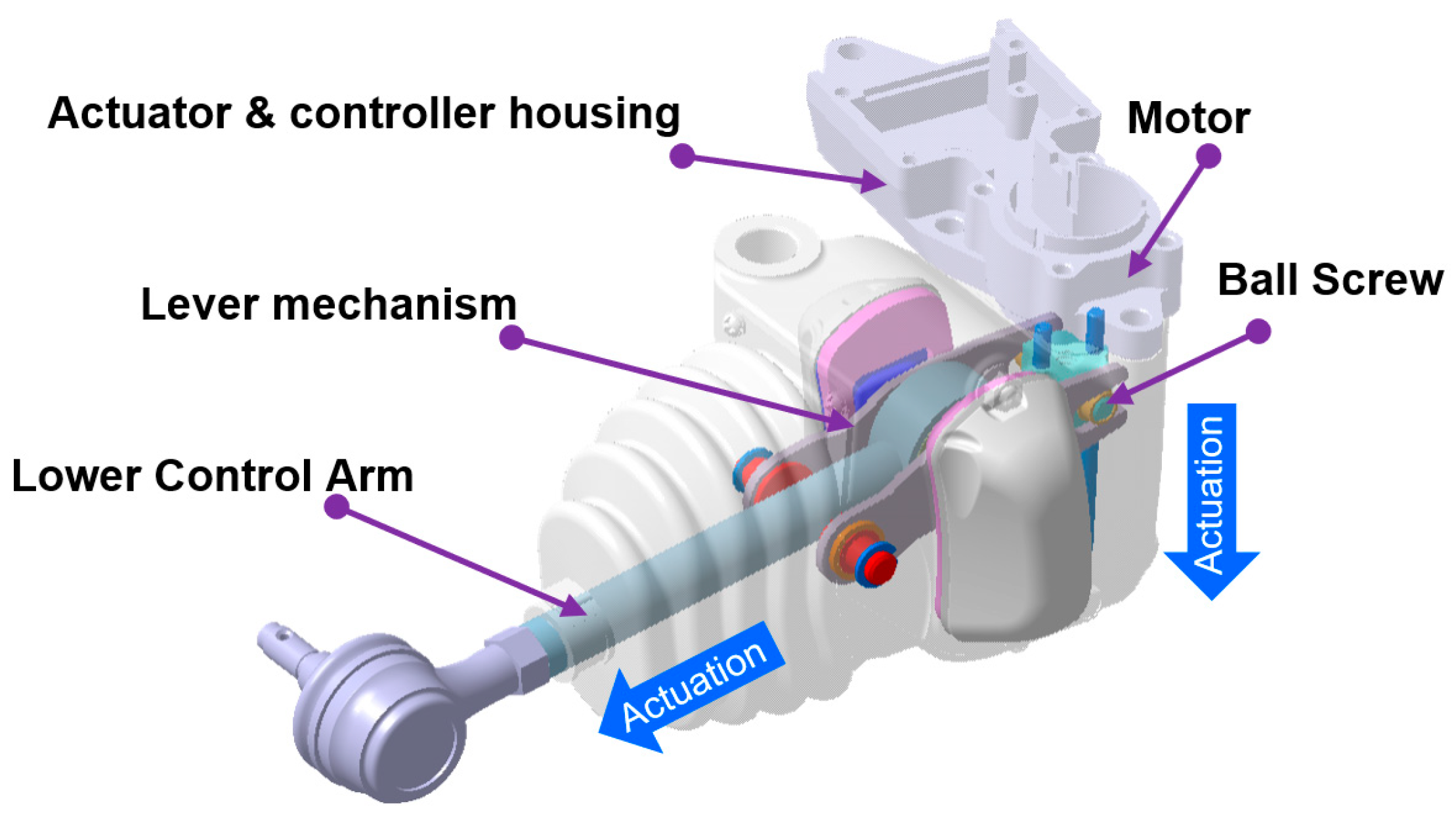
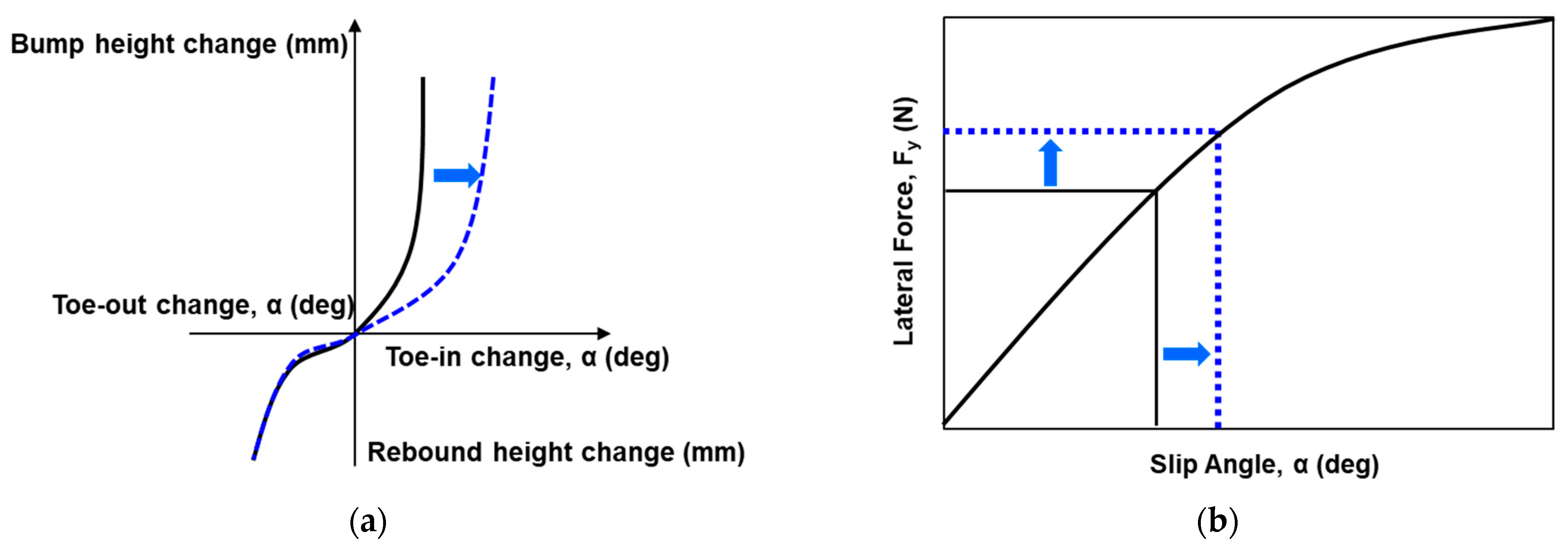
2. Independent Rear Wheel Steering System

The subject of this study is the independent rear-wheel steering system, which actively controls the rear-wheel steer angle to enhance vehicle yaw stability. Unlike conventional rear-wheel steering systems in which the left and right wheels are mechanically linked, in this system, the wheels operate independently. This feature provides advantages in terms of optimizing vehicle space and efficiently controls only the outer wheels, which have a dominant effect on vehicle stability during cornering maneuvers.
The target system achieves control of the rear-wheel steering angle by controlling the position of the assist arm, which determines the toe angle of the rear suspension components in a typical vehicle, as shown in Figure 1. This component supports a significant load during steering, and it applies the lever principle to effectively generate instantaneous control force to ensure cornering stability.
During steering maneuvers, the outer wheel and suspension of the vehicle exhibit a bump motion. At this point, the vehicle mechanically generates a specific amount of toe-in steering angle, as shown in Figure 2a, corresponding to the magnitude of the bump. This leads to the generation of lateral force, as shown in Figure 2b, in response to the change in the side-slip angle. While the bump motion mechanically generates a predetermined amount of toe angle, the independent rear-wheel steering system concurrently generates additional toe angle actively. This results in a counter-yaw moment, leading to optimal vehicle cornering stability.

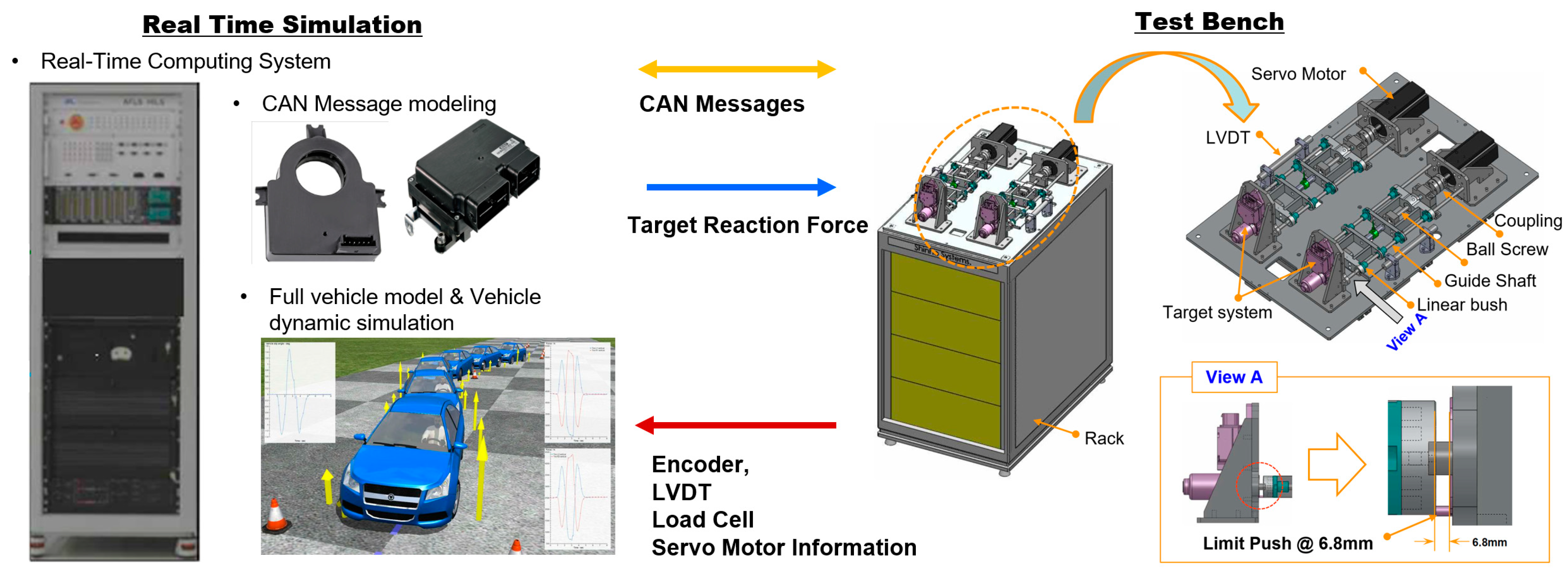
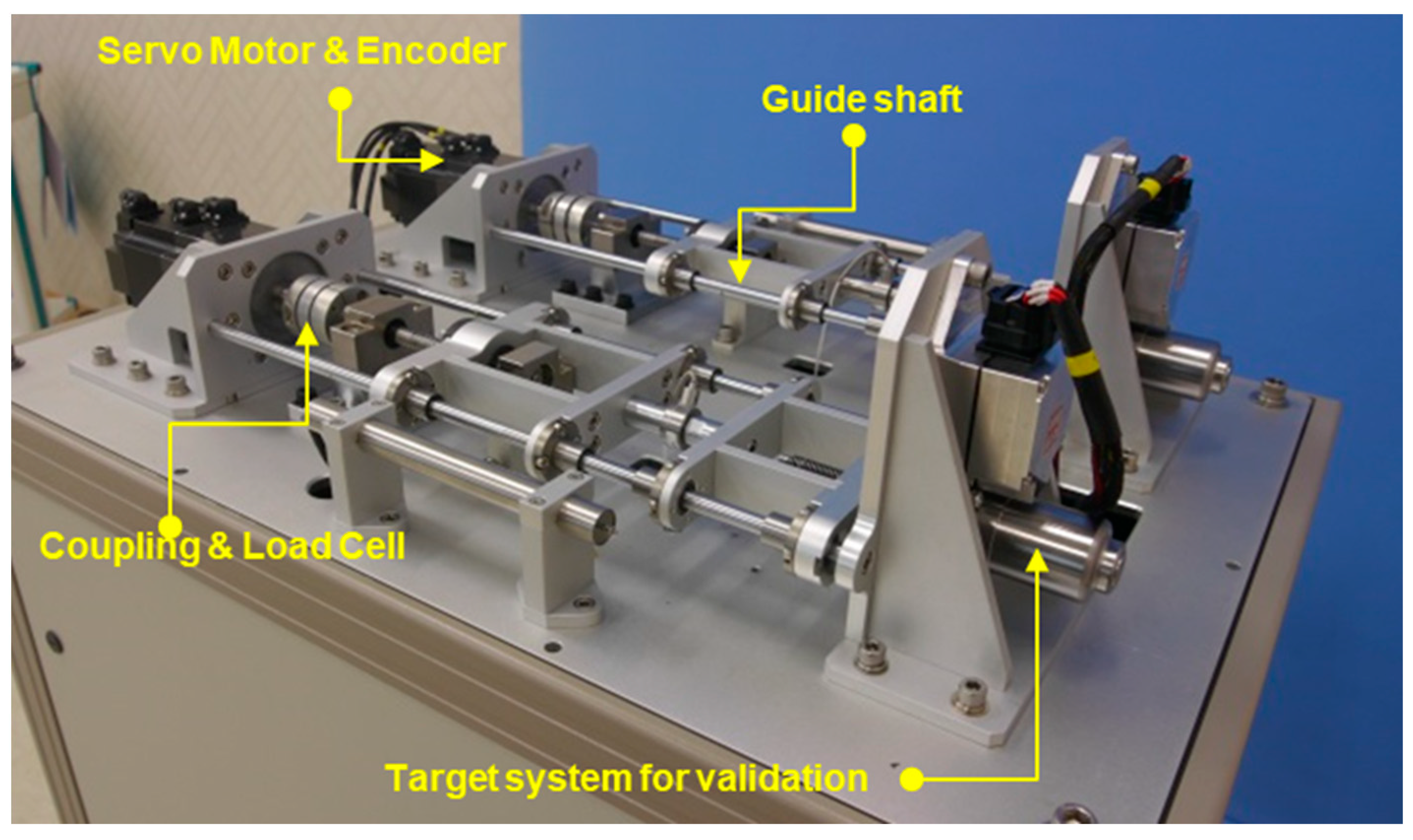
3. Design and Configuration of HILS System

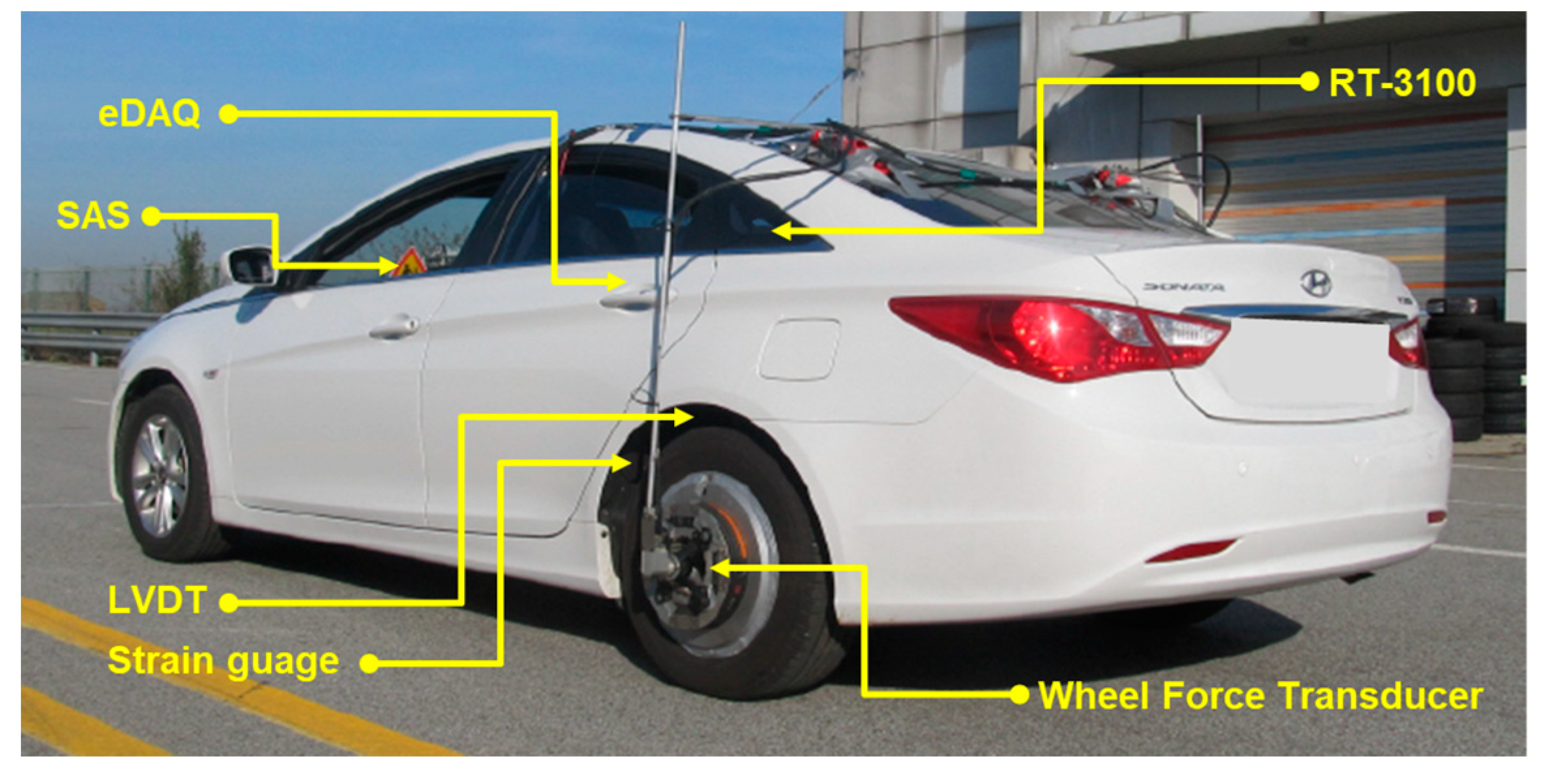
3.1. Real-Time Simulation Environment and System Configuration

The target system of the HiL simulation test consists of the operating motor unit and the control system of the independent rear-wheel steering system. The HiL simulation system was configured, as shown in Figure 3. The real-time simulation component is based on Opal-RT with the QNX operating system, which performs real-time computations. CarSim (Mechanical Simulation, Ann Arbor, MI, USA), a commercial software, is integrated for vehicle dynamics simulation. CAN systems are configured, and CAN messages are defined and coded to exchange various status information and to ensure communication between the RT platform, the target system, and the test bench.
The test bench section is designed to precisely apply the reaction force to the target system during vehicle dynamics simulation in real time. The test bench includes components such as a Servo Motor for simulating driving loads, a LVDT (Linear Variable Differential Transformer) for actuator movement sensing, a Load Cell for applied force feedback, and a guide shaft for ensuring structural robustness. Additionally, limit switches are incorporated for safety during the test.

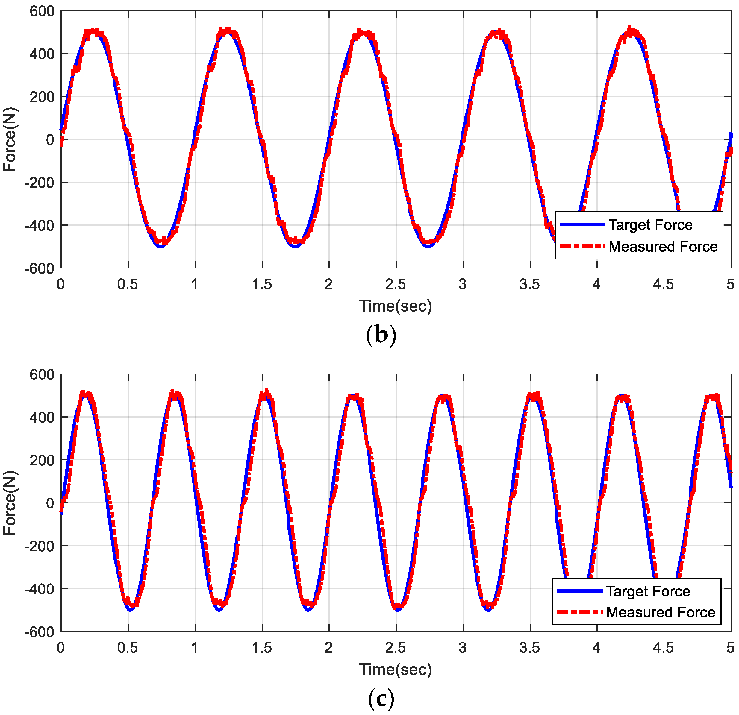
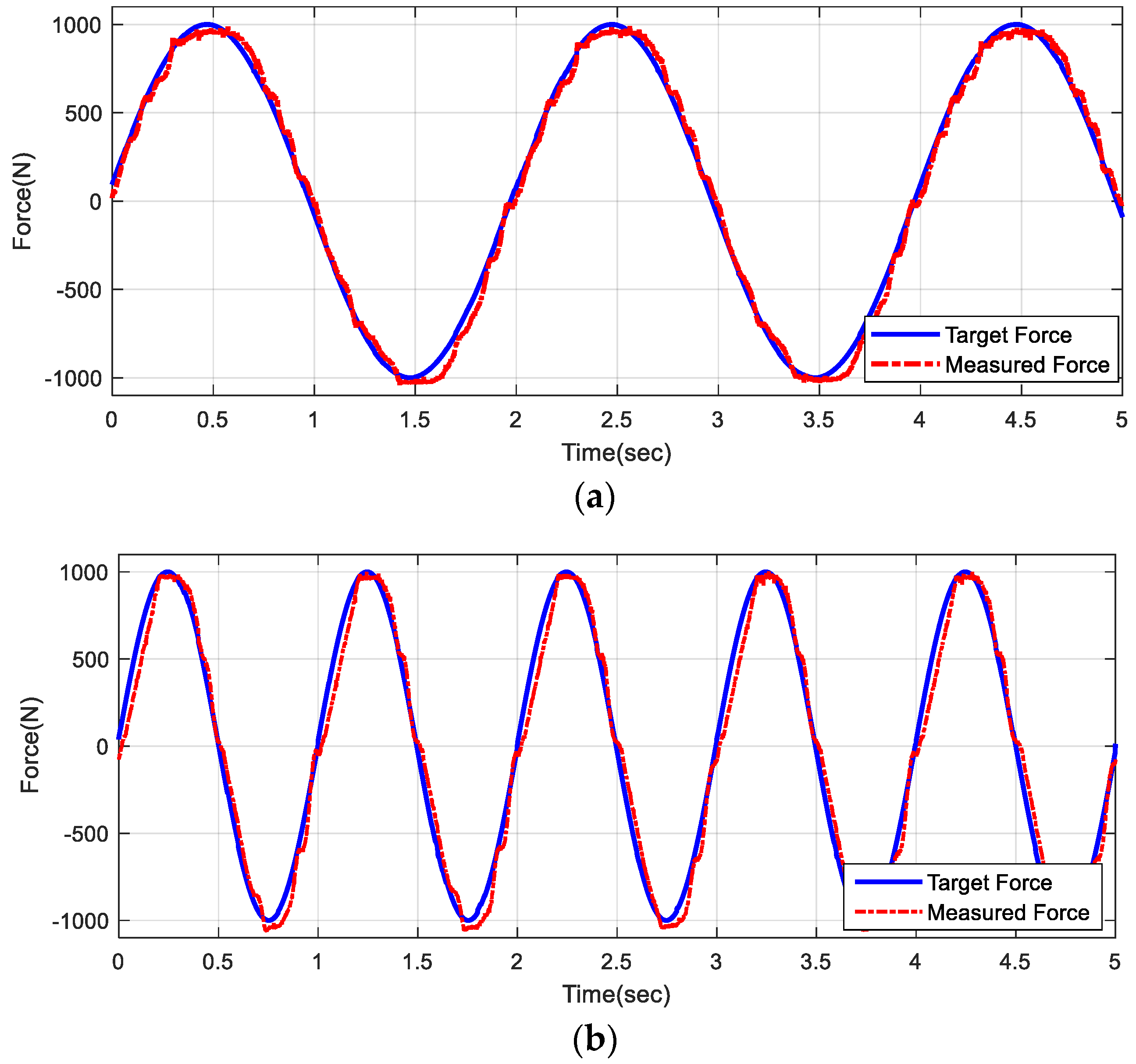
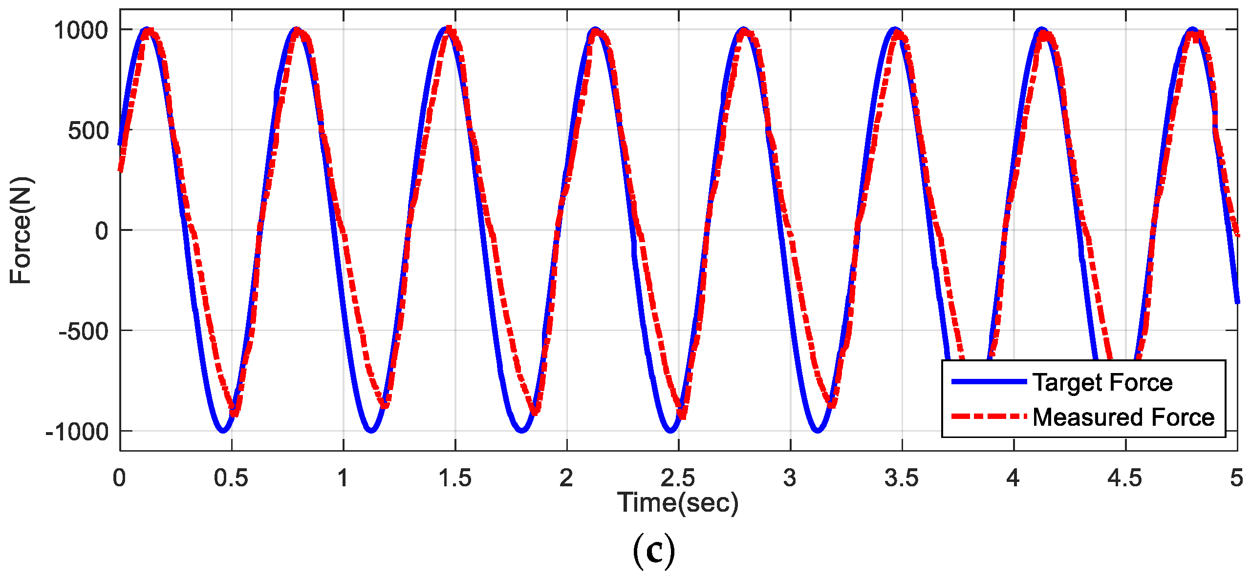
3.2. Reaction Force Generation and Control

For precise application of driving loads to the target system, it is imperative to ensure the control performance of the servo motor system. This control of the reaction force is achieved through feedback of a Load Cell. Figure 4 shows the system configuration of the test bench, while Figure 5 presents the conceptual framework for the reaction force control.
A PI controller was employed for the control logic, and it was observed that the noise present in the Load Cell measurements affected the control performance. A Low-Pass Filter based on the Backward Rectangular Approach (BRA), as shown in Equation (1), was utilized for noise control.
Y ( Z ) = F c ( Z 1 ) / ( T s   Z ) + a   X ( Z )   = T s   F c   Z Z 1 + T s   F c   Z   X ( Z )   = T s   F c ( 1 + T s   F c ) Z 1   X ( Z )
where Fc is the cut-off frequency, and Tc is the sampling time. The lower cut-off frequency of the low-pass filter effectively removes noise; however, it leads to slower updates and a characteristic that approaches the old value. A significant phase lag occurs, which adversely affects real-time computations and control performance. Therefore, to minimize signal distortion by setting the cut-off frequency of the low-pass filter as high as possible, a rate limiter was designed using Equations (2)–(5) for signal processing. First, the rate can be defined as follows:
rate = u ( i ) u ( i 1 ) t ( i ) t ( i 1 )  
where u(i) is current value, u(i − 1) is the old value, t(i) is the current time, and t(i−1) is the old time.
If   rate   >   R       y ( i ) = Δ t R + y ( i 1 )  
If   rate   <   F       y ( i ) = Δ t F + y ( i 1 )  
If   F     rate     R       y ( i ) = u ( i )  
where R is the rising slew rate as an upper limit, and F is the falling slew rate as a lower limit. If the rising slew rate exceeds the threshold value R, Equation (3) is executed. On the other hand, if the falling slew rate is less than the threshold value F, it is output, as shown in Equation (4). If the rate falls between F and R, the current input is directly output. By utilizing a rate limiter for slope control prior to applying a low-pass filter to the signal measured by the Load Cell, signal distortion is reduced, and efficient noise control is achieved simultaneously.
Figure 6 and Figure 7 show the test results for the servo motor control performance during the simulation of the reaction force. To facilitate the potential application of the proposed Hardware-in-the-Loop Simulation system to the entire target module in the future, the tracking performance of sinusoidal references at frequencies of 0.5 Hz, 1.0 Hz, and 1.5 Hz was verified for maximum forces of 500 N and 1000 N. Across all conditions, fine response and accuracy were shown for the regions of compressive force. However, relatively slower response speeds and lower accuracy were observed for the region of tensile force.
However, considering that the independent rear-wheel steering system primarily generates momentary compressive forces crucial for vehicle stabilization, these observed differences do not substantially influence the overall system evaluation. Furthermore, it should be noted that higher tracking accuracy is achieved when the target force is lower, or the input frequency is lower. Therefore, the direct load on the target system, the actuator only, is expected to be much lower than that on the assist arm, and as such, superior performance is expected.

4. Vehicle and System Modeling

To establish a HiL simulation environment, it is essential to replicate all conditions except those involving the target system. To simulate conditions equivalent to those used in real vehicle assessments, subsystem modeling must accurately reproduce the loads applied to the target system in the context of the target vehicle and virtual testing environment.
In this section, to achieve such an environment, various dynamic behaviors of the target vehicle and loads at the installation location were measured. Modeling of both the target vehicle and the subsystem was conducted based on the measured data. A specific modeling process was proposed for the subsystem, identifying modeling parameters through correlation analysis for input. The system identification method was used to model the reaction force.

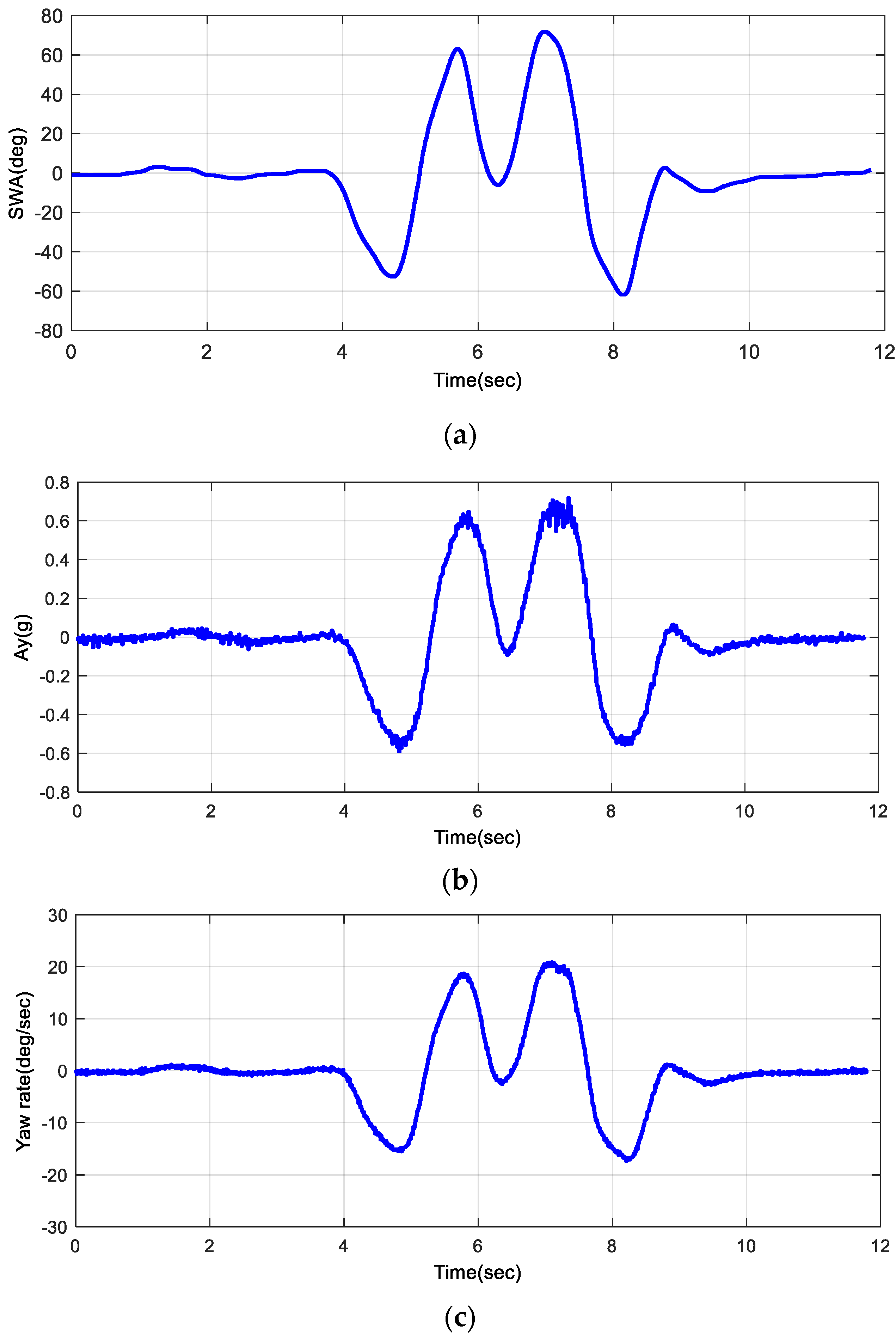
4.1. Data Acquisition for Modeling

To acquire the key data for modeling, Figure 8 shows the test environment configuration of the target vehicle for installation; Figure 9 shows key measurement locations and sensors. A Wheel Force Transducer (WFT) was utilized to measure the loads applied to the wheels during driving. An LVDT sensor was employed to measure the bump and rebound motion of the suspension, and an assist arm in which the independent rear-wheel steering system was supposed to be mounted was strain-gauged to measure loads during driving.
Additionally, the RT-3100 system was used to acquire various data related to the vehicle’s dynamic behaviors. Driver inputs were measured based on CAN communication, and an e-DAQ system was utilized to store all data during the vehicle test in real time. Table 1 presents the sensors and measured signals.
The ISO 3888-1 standard was employed as a representative test condition for analyzing the vehicle’s dynamic behavior [32]. Figure 10 shows the test conditions; the test was conducted under an entry speed condition of 80 kph by a professional test driver. Figure 11 presents the test results, showing key vehicle motion measurement variables, including (a) steering angle input, (b) lateral acceleration, and (c) yaw rate.

4.2. Modeling of Reaction Force

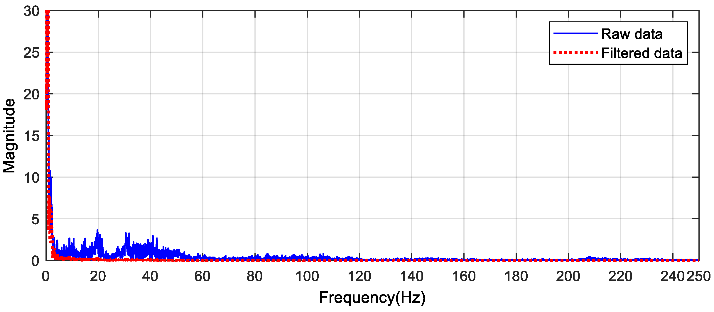
4.2.1. Signal Processing

The most critical aspect of HiL simulation configuration lies in the simulation of reaction forces for the target system. To achieve this, it is necessary to model the generation of reaction forces applied to the target system during driving simulations.
The load data obtained from the assist arm—the target subsystem to be modeled—contain unnecessary noise components. To accurately model the target subsystem, unnecessary noise was removed using a Low-Pass Filter algorithm. In this study, the Backward Rectangular Approach (BRA) method was utilized, as described in Section 3.2.
The cut-off frequency of the Low-Pass Filter was set at 10 Hz. As shown in Figure 12, the cut-off frequency was determined through frequency analysis to ensure that it did not distort system characteristics. Figure 13 shows the measured data and the data after processing through the Low-Pass Filter. Despite having a certain phase lag due to the characteristics of the Low-Pass Filter, the results maintain the dominant frequency components within the acceptable range, thus preserving the overall system characteristics. Moreover, since the results are solely utilized to design the reaction force simulation algorithm and are not intended to influence the modeling results, their effect on the modeling outcomes is considered negligible.

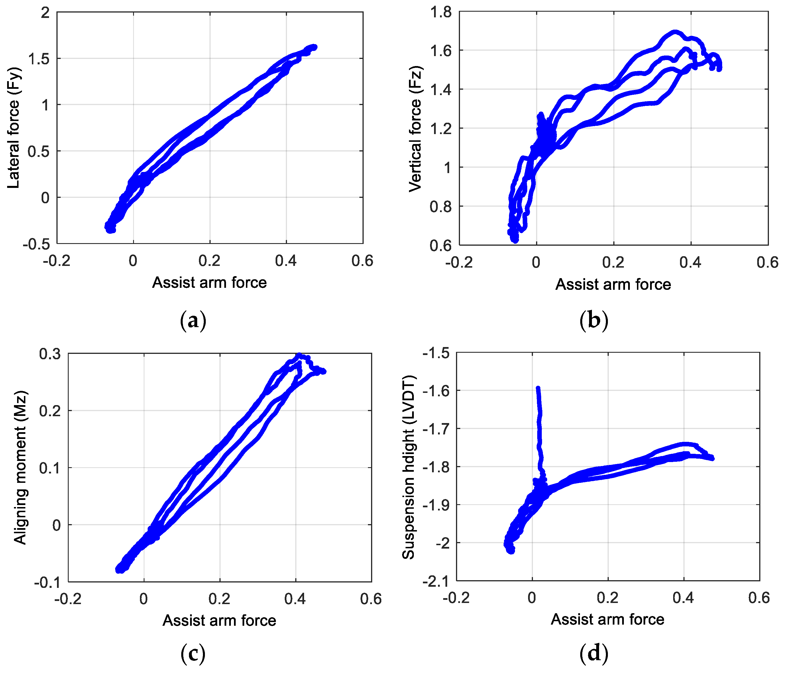
4.2.2. Correlation Analysis for Identifying Input Variable

The system identification method is often used to characterize structural responses [33,34,35]. In this study, to model the reaction forces, the system was assumed to be a Single Input–Single Output (SISO) system. To identify the dominant input variable from the force measured at the Assist Arm, correlation analysis was conducted. The input variables considered for correlation analysis are the lateral force (Fy), vertical force (Fz), and the aligning moment (Mz), as well as the suspension height, which represents the bump and rebound stroke. The correlation analysis was performed using Equation (6), in which x represents the load measured from the assist arm, and y represents the four aforementioned variables used as input variables.
r = k = 1 n ( x k x ¯ ) ( y k y ¯ ) k = 1 n ( x k x ¯ ) 2 k = 1 n ( y k y ¯ ) 2
Figure 14 shows the results of the correlation analysis; Table 2 presents results for the correlation coefficients—a very high correlation between Aligning Moment (Mz) and Lateral Force (Fy) can be observed, while both variables show correlation coefficients at a level suitable for the input variable. In this study, Aligning Moment, which has the highest correlation coefficient, was chosen as the input variable.

4.2.3. Modeling of Reaction Force

To model the reaction force generation from the Aligning Moment (Mz) to the assist arm, a maximum fourth-order SISO (Single Input–Single Output) system was assumed, as shown in Equation (7) below:
H ( j ω ) = K ( 1 + j T z 1 ω ) ( 1 + j T z 2 ω ) ( 1 + j T z 3 ω ) j ω ( 1 + j T p 1 ω ) ( 1 + j T p 2 ω ) ( 1 + j T p 3 ω )
Unknown parameters were estimated using the Recursive Parameter Estimation Algorithm as follows:
θ ( t ) = θ ( t 1 ) + K ( t ) ( y ( t ) y ( t ) )
Here, θ ( t ) is the unknown parameter to be estimated and y ( t ) is the model prediction at the ( t 1 ) th step based on y ( t ) . Additionally, the gain K ( t ) determines how much the current estimation error influences the next estimation and can be obtained as follows:
K ( t ) = Q ( t ) ψ ( t )
Here, ψ ( t ) is the change in the estimated model result y ( t ) for parameter θ . Additionally, Equations (10) and (11) were employed to estimate Q ( t ) using the Kalman Filter.
Q ( t ) = P ( t 1 ) R 2 + ψ ( t ) T P ( t 1 ) ψ ( t )
P ( t ) = P ( t 1 ) + R 1 P ( t 1 ) ψ ( t ) ψ ( t ) T P ( t 1 ) R 2 + ψ ( t ) T P ( t 1 ) ψ ( t )
For each condition from the first to fourth order, the optimal parameters were estimated through 20 iterations each. For the third- to fourth-order models, there was no significant advantage compared to the second-order model. Therefore, a second-order system, which is suitable for representing the behavior of a general physical system, was selected, as shown in Equation (12).
H ( j ω ) = 0.014963 1 + 0.026748 j ω j ω ( 1 + 90.978 j ω )
The raw data from the measured aligning moment (Mz) was used as the model input for validation; it was compared with the results obtained from the proposed model and the measured data. Figure 15 shows the comparison results. Although a slight discrepancy can be seen at around 7.5 s, this corresponds to a non-linear behavior region resulting from excessive tire–road surface slip, which is a momentary phenomenon in real-world vehicle dynamics. The presented SISO system assumes linearity and does not account for such non-linearities—something that is also considered a limitation of the second-order model. Considering the results and practical applicability of the simulation environment, this level of accuracy is considered acceptable.

4.2.4. Force Attenuation Mechanism

To amplify the force applied by the motor for rear-wheel steering angle control, a unique mechanical structure was designed. The final load applied to the target motor control system, in comparison to the load on the assist arm, was attenuated through the inherent mechanism. The mechanism of the presented system is shown in Figure 16a; it is approximated as presented in Figure 16b.
In Figure 16a, A C ¯ corresponds to the assist arm of a conventional vehicle while B D ¯ representing the unique mechanism of the proposed independent rear-wheel steering system. The lever principle operates around Point B , transmitting the road load, while it is assumed there is no loss of transmitted load around Point C . Therefore, the load directly applied to the target system can be approximated using Equations (13) to (14), as follows:
F D C D ¯ = B C ¯ F B
F D = C D ¯ B D ¯ F z
Here, F z is as defined in Equation (15) and d corresponds to the operational stroke of the target motor.
F z = F y sin ( tan 1 ( d / B D ¯ ) )
The attenuated force resulting from the load generated by the reaction force on the assist arm, as presented in Section 4.2.3, provides the ultimate target force applied to the motor of the independent rear-wheel steering system in the HiL simulation system being developed throughout this study.

4.3. Modeling of Target Vehicle

To conduct HiL simulation tests on the target system, a reliable full vehicle dynamic model is essential for real-time simulation of vehicle dynamic behaviors. Leveraging crucial data acquired from the subject vehicle’s Suspension Parameter Measuring Device (SPMD) and dynamic behavior measurement during vehicle testing, a full vehicle simulation model was carried out using CarSim (Mechanical Simulation, Ann Arbor, MI, USA), a commercial software specifically designed for vehicle dynamics. Figure 17 shows the results of the vehicle modeling, with a focus on lateral dynamics, as it is a primary concern in this study. The model ensures accuracy in both longitudinal and lateral behaviors, with the following results: correlation coefficient of 0.9876 and maximum error of 4.5% in lateral dynamics; correlation coefficient of 0.9961 and maximum error of 0.1% in longitudinal dynamics.

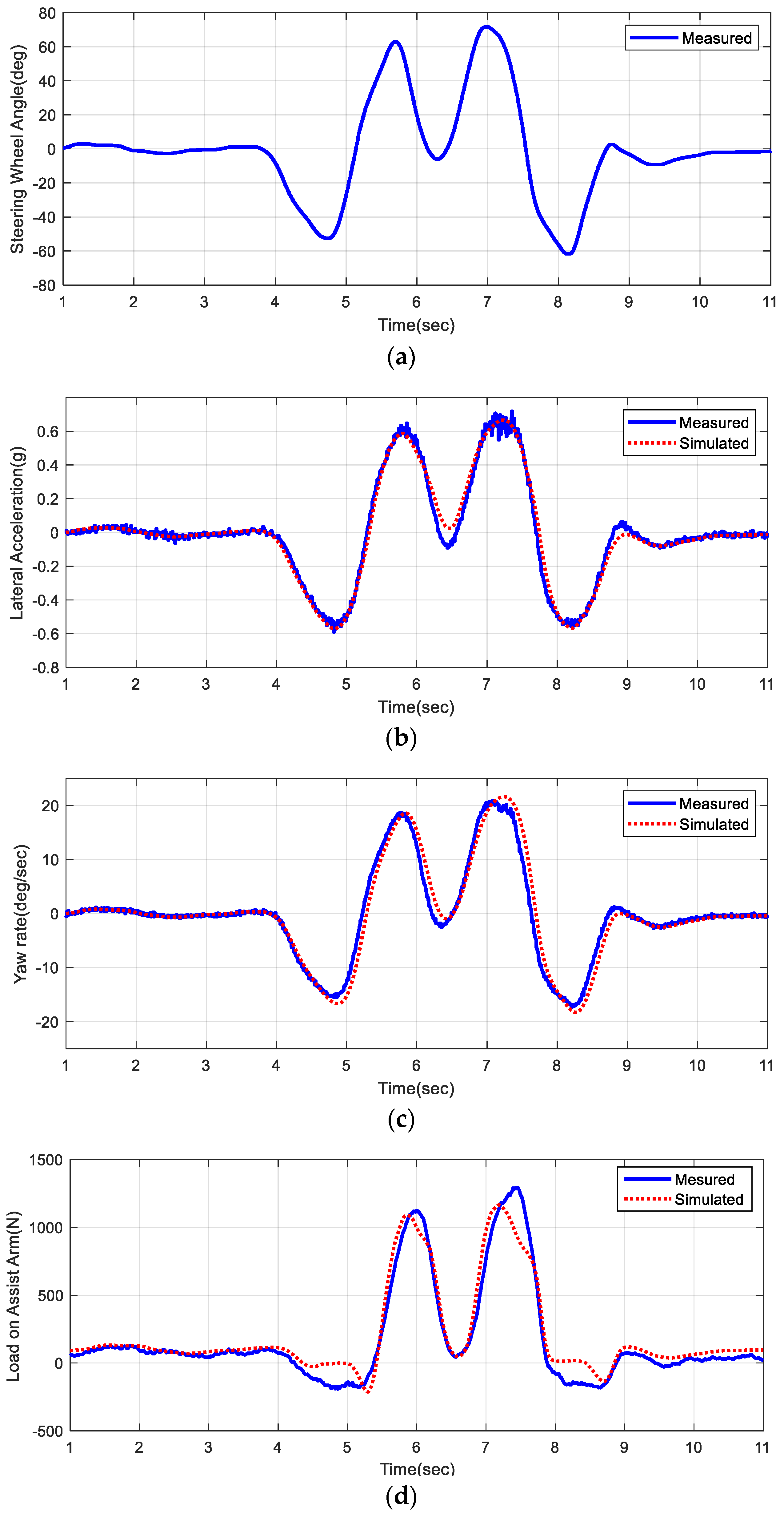
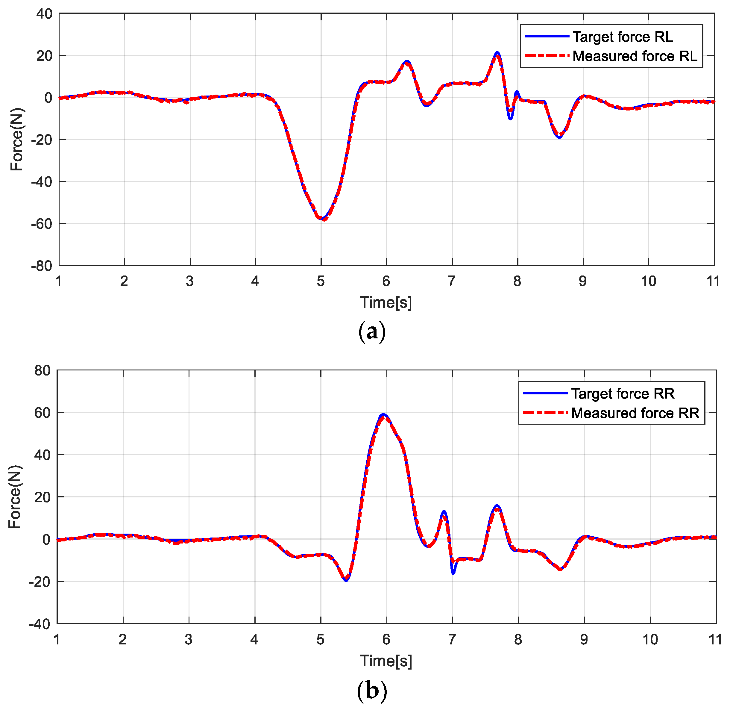
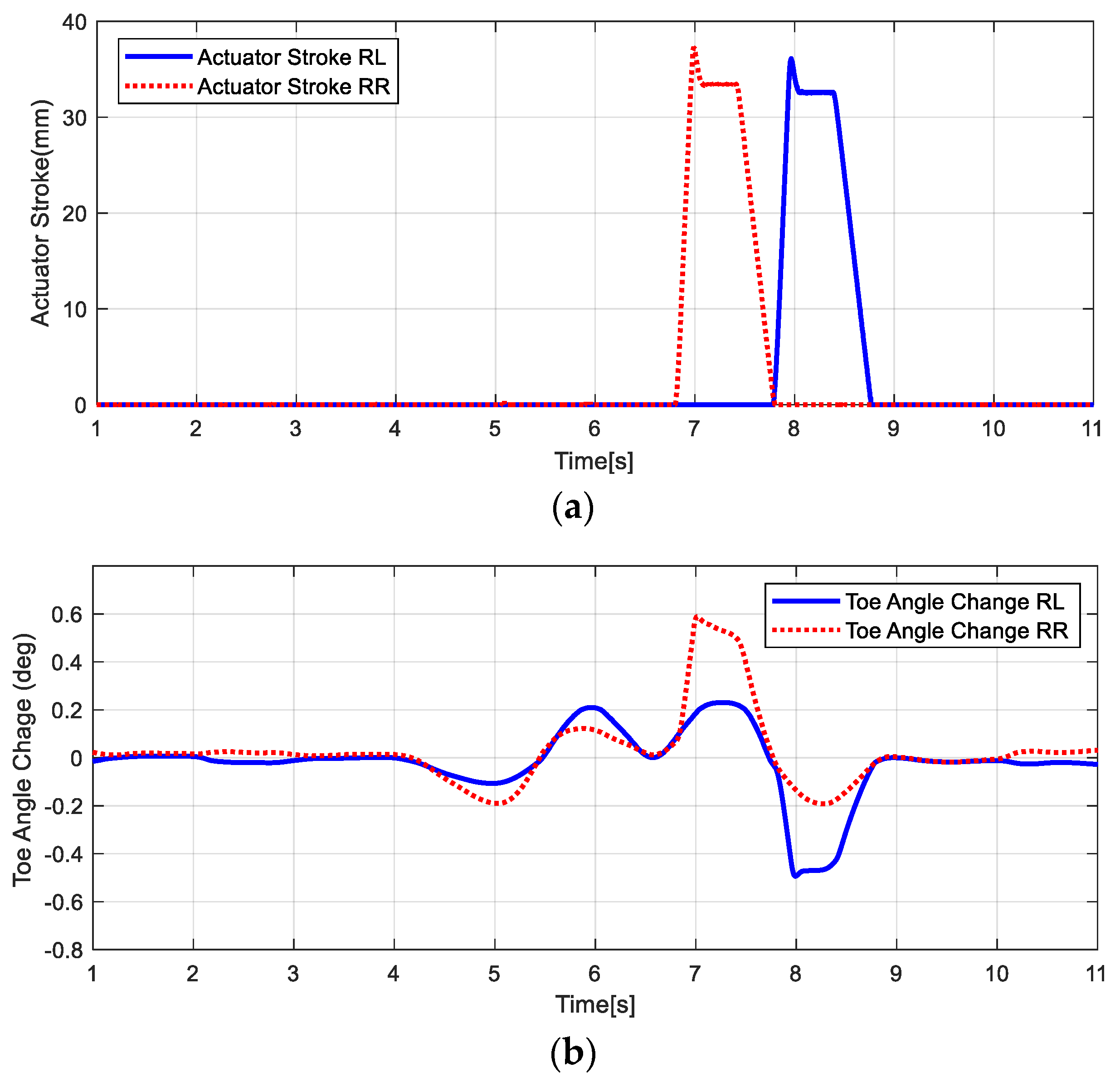
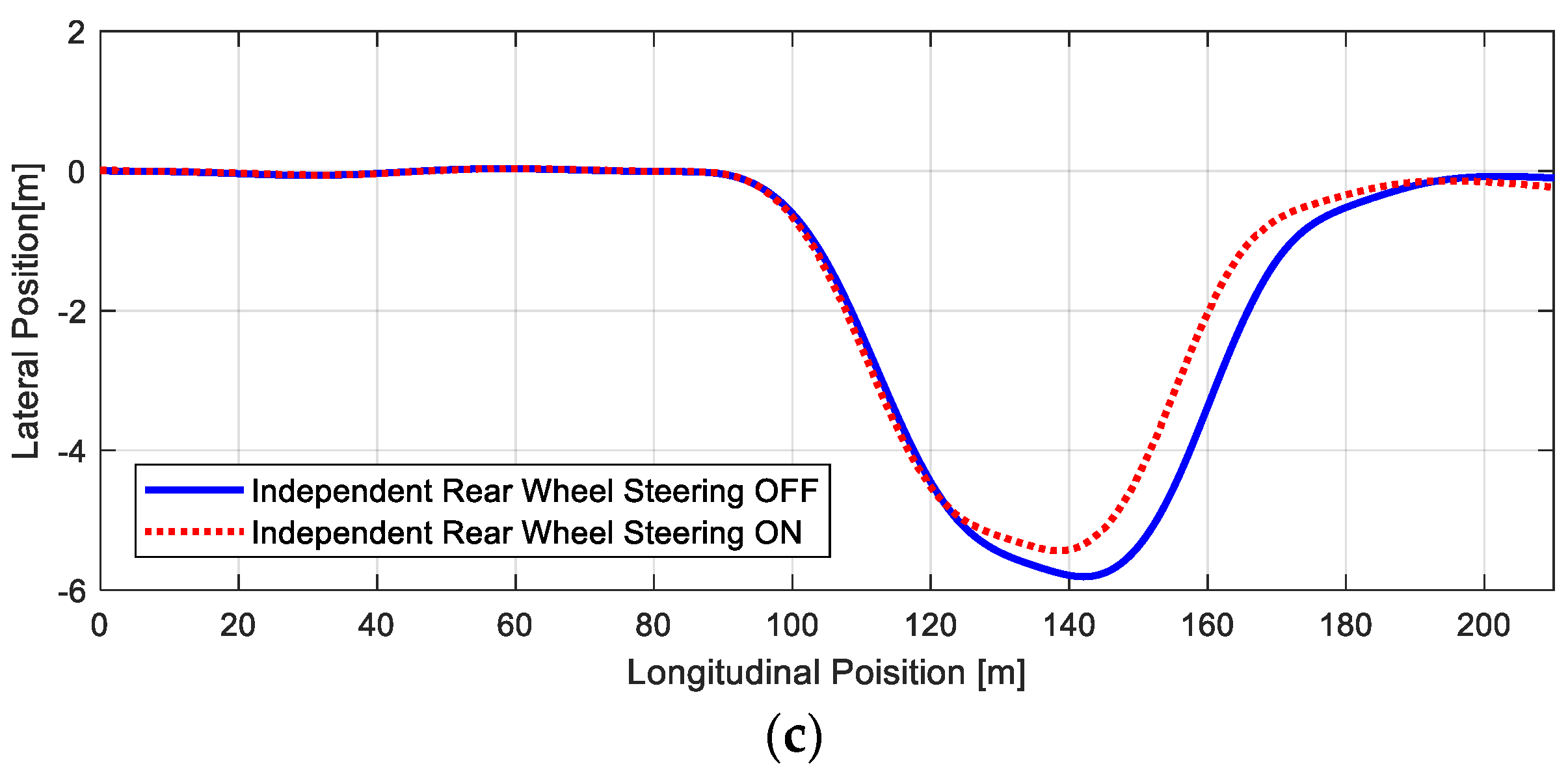
5. Test Results of Target System Using HiL Simulation

The influence of the Independent Rear Wheel Steering System on the vehicle driving stability was evaluated using the Hardware-in-the-Loop simulation environment developed in Section 3 and Section 4. Figure 18 shows the reaction force generation performance applied to the target system, an important aspect of the proposed HiL simulation environment. The maximum reaction force was 60 N; the overall behavior operates at frequencies up to 1 Hz. As mentioned in Section 3, this range ensures that system maintains satisfactory performance, with a maximum error of approximately 2.9%. However, a relatively notable control error of approximately 31.4% was observed in specific regions, particularly for behaviors exceeding 4 Hz. Nevertheless, this is considered insignificant when evaluating the performance of the independent rear-wheel steering actuator, as these instances of minor target force occurrence are temporary.
Figure 19 shows the behavior of the Independent Rear Wheel Steering System during the HiL simulation test. In Figure 19a, the actuator stroke of both Independent Rear Wheel Steering Actuators is shown; Figure 19b shows the changing toe angle during the HiL simulation test. The observed variation when the actuators are inactive is due to the toe angle change caused by jounce motion, influenced by the vehicle’s mechanical structure. Substantial increases in toe angle change are observed when the actuators are engaged on each side. These changes affect vehicle yaw stability or directional stability, as illustrated in Figure 20. Figure 20 presents vehicle dynamic behavior during the HiL simulation test based on the operation of the Independent Rear Wheel Steering System. Figure 20a,b compare important parameters for lateral dynamics analysis, specifically lateral acceleration and yaw rate, showing reductions of approximately 5.1% and 5.2%, respectively, when the system is active. Consequently, as shown in Figure 20c, the lateral offset decreased by about 6.3%, representing an improvement in maneuverability. As explained in Section 2 and shown in Figure 2, an additional toe angle results in a larger lateral force generation. Consequently, the increased lateral force not only enhances maneuverability but also improves the vehicle’s stability. Based on these results, it can be concluded that the independent rear-wheel steering system of the vehicle enhanced both steering stability and path-tracking performance.

6. Discussion and Conclusions

The geometric alignment of an automobile suspension greatly influences driving stability. The alignment relies on a mechanically linked structure that passively adjusts to environmental changes during vehicle motion. However, in this study, using an independent rear-wheel steering system, active enhancement of vehicle driving stability was achieved and validated, surpassing the limits of predefined mechanical changes. A HiL simulation environment was developed for evaluating the independent rear-wheel steering system at the laboratory level. For this purpose, a system capable of real-time simulation of all environments with the independent rear-wheel steering system’s dedicated actuator and control system was constructed. A high-precision full-vehicle model was developed using SPMD and vehicle test data, ensuring correlation. A communication interface based on CAN communication was also developed to facilitate the communication of the control system and vehicle information during the HiL simulation test. Moreover, a load interface model with actuators, not available in commercial vehicle simulation software, was defined and modeled by conducting correlation analysis on various factors that influence the target system. The variable exhibiting the strongest correlation was selected to serve as an input parameter for the reaction force modeling process in system identification. A commercial servo motor system was utilized to realize reaction force generation and control precision.
Through the proposed evaluation environment, enhancement of vehicle driving stability was validated when the independent rear-wheel steering system was activated: reductions of approximately 5% in both lateral acceleration and yaw rate were achieved. The proposed HiL simulation system not only facilitates performance evaluation but also allows various driving tests to be conducted at the laboratory level before the actual vehicle test. The HiL simulation test environment effectively reduces costs and time for research into control logic and tuning of the development system and eliminates potential risks during real-world tests.
Furthermore, leveraging the system identification method based on target vehicle test data, the proposed modeling approach for a specific part of the evaluation target system is highly effective and precise. Therefore, it is expected to be easily applicable to the development of HiL simulation systems for other parts, contributing to process improvement and control technology development for active chassis control systems. By virtually constructing all environments except for the prototype, cost-effective software development and performance evaluation equivalent to real-world tests were achieved, leading to expected savings in time and costs.

Funding

This research was funded by the Ministry of Trade, Industry and Energy (MOTIE, Korea), grant number 20014983 and 20014984.

Data Availability Statement

Data sharing is not applicable due to institute policy.

Conflicts of Interest

The author declares no conflict of interest.

References

  1. Yang, H.; Liu, W.; Chen, L.; Yu, F. An adaptive hierarchical control approach of vehicle handling stability improvement based on Steer-by-Wire systems. Mechatronics 2021, 77, 102583. [Google Scholar] [CrossRef]
  2. Li, L.; d’Andréa-Novel, B.; Quadrat, A. Longitudinal and lateral control for four wheel steering vehicles. IFAC Pap. 2020, 53, 15713–15718. [Google Scholar] [CrossRef]
  3. Wang, L.; Pang, H.; Wang, P.; Liu, M.; Hu, C. A yaw stability-guaranteed hierarchical coordination control strategy for four-wheel drive electric vehicles using an unscented Kalman filter. J. Frankl. Inst. 2023, 360, 9663–9688. [Google Scholar] [CrossRef]
  4. Chen, W.; Liang, X.; Wang, Q.; Zhao, L.; Wang, X. Extension coordinated control of four wheel independent drive electric vehicles by AFS and DYC. Control. Eng. Pract. 2020, 101, 104504. [Google Scholar] [CrossRef]
  5. Appleyard, M.; Wellstead, P.E. Active suspensions: Some background. IEE Proc. Control. Theory Appl. 1995, 142, 123–128. [Google Scholar] [CrossRef]
  6. Gillespie, T.D. Fundamentals of Vehicle Dynamics; SAE International: Warrendale, PA, USA, 1992. [Google Scholar]
  7. He, H.; Li, Y.; Clare, L.; Jiang, J.Z.; Sakka, M.A. A configuration-optimisation method for passive-active-combined suspenstion design. Int. J. Mech. Sci. 2023, 258, 108560. [Google Scholar] [CrossRef]
  8. Shi, X.; Yu, Q.; Wu, Z.; Li, J.Y.; Zhu, S. Active control for vehicle suspension using a self-powered dual-function active electromagnetic damper. J. Sound Vib. 2023, 569, 117976. [Google Scholar] [CrossRef]
  9. Chen, G.; Jiang, Y.; Tang, Y.; Xu, X. Revised adaptive active disturbance rejection sliding mode control strategy for vertical stability of active hydro-pneumatic suspension. ISA Trans. 2023, 132, 490–507. [Google Scholar] [CrossRef]
  10. Liu, P.; Zheng, M.; Ning, D.; Zhang, Z.; Du, H. Decoupling vibration control of a semi-active electrically interconnected suspension based on mechanical hardware-in-the-loop. Mech. Syst. Signal Process. 2022, 166, 108455. [Google Scholar] [CrossRef]
  11. Kim, J.; Lee, T.; Kim, C.; Yi, K. Model predictive control of a semi-active suspension with a shift delay compensation using preview road information. Control. Eng. Pract. 2023, 137, 105584. [Google Scholar] [CrossRef]
  12. Luo, J.; Li, P.; Li, P.; Cai, Q. Observer-based multi-objective integrated control for vehicle lateral stability and active suspension design. J. Sound Vib. 2021, 508, 1169222. [Google Scholar] [CrossRef]
  13. Cho, S.; Im, J. Analysis of vehicle dynamic with car suspension design. J. Korean Soc. Mech. Eng. 1993, 33, 871–883. [Google Scholar]
  14. Min, H.K.; Tak, T.O.; Lee, J.M. Kinematic design sensitivity analysis of suspension system using direct differentiation. Trans. Korean Soc. Automot. Eng. 1997, 5, 38–48. [Google Scholar]
  15. Song, S.J.; Moon, H.K.; Cho, B.K. A study on the effects of flexibilities of suspension system of a vehicle for handling performance. Trans. Korean Soc. Automot. Eng. 1998, 6, 186–197. [Google Scholar]
  16. Zhang, Y.; Xiao, P.; Palmer, T.; Farahani, A. Vehicle Chassis/Suspension Dynamics Analysis—Finite Element Model vs. Rigid Body Model; SAE Technical Paper 980900; SAE International: Warrendale, PA, USA, 1998. [Google Scholar]
  17. Sohn, S.H.; Shin, H.-W.; Lee, H.-W. The Improvement of Handling Performances through the Sensitivity Analysis Validated by the K & C Test; SAE Technical Paper 980898; SAE International: Warrendale, PA, USA, 1998. [Google Scholar]
  18. Sohn, J.; Kim, K.; Yoo, W. Selection of toe geometry and bushing stiffness to improve the vehicle handling characteristics. Trans. Korean Soc. Automot. Eng. 1999, 7, 186–193. [Google Scholar]
  19. Choi, H.; Kim, S.; Han, S.; Lee, S.; Oh, Y.; Lee, U.; Bae, H. Development of Optimized Actuator for Active Geometry Control Suspension; SAE Technical Paper 2007-01-0409; SAE International: Warrendale, PA, USA, 2007. [Google Scholar]
  20. Lee, S. A Study for the Vehicle Dynamic Enhancement via the Active Kinematic Control of Suspension. Ph.D. Thesis, Hanyang University, Seoul, Republic of Korea, 1996. [Google Scholar]
  21. Nemeth, B.; Gaspar, P. Nonlinear analysis and control of a variable-geometry suspension system. Control. Eng. Pract. 2017, 61, 279–291. [Google Scholar] [CrossRef]
  22. Feng, Z.; Yu, M.; Cheng, C.; Evangelou, S.A.; Jaimoukha, I.M.; Dini, D. Uncertainties investigation and mu-synthesis control design for a full car with series active variable geometry suspension. IFAC Pap. 2020, 53, 13882–13889. [Google Scholar]
  23. Fenyes, D.; Fazekas, M.; Nemeth, B.; Gaspar, P. Implementation of a variable-geometry suspension-based steering control system. Veh. Syst. Dyn. 2022, 60, 2018–2035. [Google Scholar] [CrossRef]
  24. Nissimagoudar, P.C.; Mane, V.; Gireesha, H.M.; Iyer, N.C. Hardware-in-the-loop (HIL) simulation Technique for an Automotive Electronics Course. In Proceedings of the 9th World Engineering Eduacation Forum, Chennai, India, 13–16 November 2019. [Google Scholar]
  25. Han, S.S.; Hwang, Y.K.; Nam, K.S. Development of an Air Suspension System HILS with Full Vehicle Model. In Proceedings of the KSAE Annual Conference Proceedings, Incheon, Republic of Korea, 24–26 November 2009. [Google Scholar]
  26. Traphoner, P.; Olma, S.; Kohlstedt, A.; Fast, N.; Jaker, K.P.; Trachtler, A. Hardware-in-the-Loop Simulation for a Multiacxial Suspension Test Rig with a Nonlinear Spatial Vehicle Dynamics Model. IFAC Pap. 2019, 52, 109–114. [Google Scholar]
  27. Hebin, W.; Rui, B. Design of Hardware-In-Loop Simulation Platform for Air Suspension Systems. IFAC Pap. 2018, 51, 142–145. [Google Scholar] [CrossRef]
  28. Jung, J.C.; Lee, K.S.; Kim, S.Y. Control of Active/Semi-Active Suspensions for Commercial Vehicles. In Proceedings of the KSAE Annual Conference Proceedings, Seoul, Republic of Korea, 29–30 November 1996. [Google Scholar]
  29. Kim, H.S.; Lee, H.C. Height and Leveling Control of Automotive Air Suspension System Using Sliding Mode Approach. IEEE Trans. Veh. Technol. 2011, 60, 2027–2041. [Google Scholar]
  30. Mihalic, F.; Truntic, M.; Hren, A. Hardware-in-the-Loop simulations: A Historical Overview of Engineering Challenges. Electronics 2022, 11, 2462. [Google Scholar] [CrossRef]
  31. Liang, J.; Lu, Y.; Pi, D.; Yin, G.; Zhuang, W.; Wang, F.; Feng, J.; Zhou, C. A Decentralized Cooperative Control Framework for Active Steering and Active Suspension: Multi-Agent Approach. IEEE Trans. Transp. Electrif. 2022, 8, 1414–1429. [Google Scholar] [CrossRef]
  32. ISO 3888-1; Passenger Cars—Test Track for a Severe Lane Change Manoeuvre—Part 1: Double Lane Change. Available online: https://www.iso.org/standard/67973.html (accessed on 11 September 2023).
  33. Zhou, K.; Wang, Z.; Gao, Q.; Yuan, S.; Tang, J. Recent advances in uncertainty quantification in structural response characterization and system identification. Probabilistic Eng. Mech. 2023, 74, 103507. [Google Scholar] [CrossRef]
  34. Quan, S.; Wang, Y.X.; Xiao, X.; He, H.; Sun, F. Feedback linearization-based MIMO model predictive control with defined pseudo-reference for hydrogen regulation of automotive fuel cells. Appl. Energy 2021, 293, 116919. [Google Scholar] [CrossRef]
  35. Worden, K.; Hickey, D.; Haroon, M.; Adams, D.E. Nonlinear system identification of automotive dampers: A time and frequency-domain analysis. Mech. Syst. Signal Process. 2009, 23, 104–126. [Google Scholar] [CrossRef]
Figure 1. 3D design of independent rear-wheel steering system.
Machines 11 00996 g001
Figure 2. Effect of rear-wheel steering change: (a) toe change in bump motion; (b) Lateral force change relative to toe change
Machines 11 00996 g002
Figure 3. Configuration of the hardware-in-the-loop simulation system.
Machines 11 00996 g003
Figure 4. Configuration of test bench section.
Machines 11 00996 g004
Figure 5. Framework for reaction force control.
Machines 11 00996 g005
Figure 6. Control performance of reaction force generation for −500 N~+500 N, (a) 0.5 Hz, (b) 1.0 Hz, and (c) 1.5 Hz.
Machines 11 00996 g006aMachines 11 00996 g006b
Figure 7. Control performance of reaction force generation for −1000 N~+1000 N, (a) 0.5 Hz, (b) 1.0 Hz, and (c) 1.5 Hz
Machines 11 00996 g007aMachines 11 00996 g007b
Figure 8. Configuration of Vehicle Test Environment.
Machines 11 00996 g008
Figure 9. Sensors for measurements: (a) SAS (Steering Angle Sensor), (b) WFT (Wheel Force Transducer), (c) strain gauge on the Assist Arm, (d) height sensor, (e) RT-3100, and (f) eDAQ.
Machines 11 00996 g009
Figure 10. Test Condition, ISO 3888-1, Passenger cars—test track for a severe lane-change maneuver.
Machines 11 00996 g010
Figure 11. Measurement results: (a) steering angle input, (b) lateral acceleration, and (c) yaw rate.
Machines 11 00996 g011
Figure 12. Frequency analysis of measured data of assist arm.
Machines 11 00996 g012
Figure 13. Comparisons of raw data and filtered data.
Machines 11 00996 g013
Figure 14. Correlation analysis of assist arm force: (a) vs. lateral force, (b) vs. vertical force, (c) vs. aligning moment, and (d) vs. suspension height.
Machines 11 00996 g014
Figure 15. Modeling results of reaction force on assist arm: (a) model input and (b) comparison between measured data and model output.
Machines 11 00996 g015
Figure 16. Kinematic system of independent rear-wheel steering system: (a) system overview and (b) simplified system movement.
Machines 11 00996 g016
Figure 17. Vehicle modeling results: (a) steering angle input, (b) lateral acceleration, (c) yaw rate, and (d) reaction force on assist arm.
Machines 11 00996 g017
Figure 18. Reaction force generation and control performance of the HiL simulation system: (a) rear-left side (RL) and (b) rear-right side (RR).
Machines 11 00996 g018
Figure 19. Independent rear-wheel steering system behavior during HiL simulation test: (a) actuator stroke and (b) toe-angle change.
Machines 11 00996 g019
Figure 20. Comparison of vehicle dynamic behavior of independent rear-wheel steering system: (a) lateral acceleration, (b) yaw rate, and (c) trajectory.
Machines 11 00996 g020aMachines 11 00996 g020b
Table 1. List of Sensors and Signals.
Sensor TypeLocationSignal TypeNumber of
Channels
SASSteering Wheel ColumnSteering wheel angle, Steering wheel angular velocity2
WFTRear Wheel (L/R)Fx, Fy, Fz, Mx, My, Mz12
Strain GaugeRear Assist Arm (L/R)Force on the assist arms2
LVDTRear Suspension (L/R)Bump/rebound stroke2
RT-3100Center of VehicleVehicle position, velocity, acceleration, heading angle, pitch, roll, yaw angle,16
Table 2. Results of Correlation Analysis.
Output VariableInput VariableCorrelation Factor
Assist Arm ForceLateral Force (Fy)r1 = 0.9801
Assist Arm ForceVertical Force (Fz)r2 = 0.8108
Assist Arm ForceAligning Moment (Mz)r3 = 0.9921
Assist Arm ForceSuspension Heightr4 = 0.7191
Disclaimer/Publisher’s Note: The statements, opinions and data contained in all publications are solely those of the individual author(s) and contributor(s) and not of MDPI and/or the editor(s). MDPI and/or the editor(s) disclaim responsibility for any injury to people or property resulting from any ideas, methods, instructions or products referred to in the content.

