Article

An Overview of Grounding Design and Grounding Fault Detection and Location Methods for a Multiphase Rectifier Generator Power Supply System

National Key Laboratory of Electromagnetic Energy, Naval University of Engineering, Wuhan 430033, China
*
Author to whom correspondence should be addressed.
Machines 2023, 11(11), 985; https://doi.org/10.3390/machines11110985
Submission received: 14 September 2023 / Revised: 12 October 2023 / Accepted: 20 October 2023 / Published: 24 October 2023
(This article belongs to the Section Machines Testing and Maintenance)

Abstract

:
A multiphase rectifier generator is important power generation equipment in DC power systems in transportation fields such as ships and aviation. Grounding design and grounding fault detection and positioning are key technologies for the safe operation of the power system. This article aims to systematically elaborate on the current research status of its related content. Firstly, the topological structure characteristics of the multiphase rectifier generator power supply system are introduced, the advantages and disadvantages of different grounding methods, position selection, and other design schemes are analyzed, and reasonable suggestions are given for the selection of grounding resistance. Secondly, a brief introduction is given to the research progress on ground fault detection and location in the medium voltage DC integrated power systems of ships, and the characteristics of typical methods for ground fault detection and location in DC power grid systems are summarized. Finally, the future research directions are outlined.

1. Introduction

A ship integrated power system can realize the integrated and optimized application of the whole ship’s energy, greatly enhancing ship handling, maneuverability, and acoustic stealth [1,2]. It is the only way to support all kinds of high-energy weapons on board, and it is known as the “third revolution” of ship power systems [1,2]. With the rapid development of electrotechnical materials, electronic components, and protection and control technology, countries around the world are actively laying out and carrying out research related to the integrated power systems of ships, realizing part of the engineering application on ships [3,4,5]. Compared to medium-voltage alternating current (AC) technology, the medium-voltage direct current (DC) integrated power system takes a twelve-phase rectifier generator as its main power supply, which has a good suitability, higher power density, and more flexible grid operation, representing the direction of the future development of the integrated power systems on board ships [6,7,8].
A ground fault is a common power system short-circuit fault [9,10]. The medium-voltage DC power system belongs to the typical AC and DC hybrid system, and a single-phase ground fault is most likely to occur on the AC side [11,12] and a unipolar ground fault on the DC side [13,14,15]. When a grounding fault occurs, a fault current loop will be formed between the system grounding point and the fault point, and there is a safety risk of damaging the line insulation or even jeopardizing the system equipment due to excessive fault current or voltage transients [16].
In order to solve the hazardous effects of grounding faults, research can be carried out mainly considering two aspects: one is to optimize the design of the system grounding scheme, including the selection of the grounding method and grounding location [17,18,19], which can directly affect the insulation requirements of the power system and the reliability of the power supply [20,21], etc.; and the other is to explore fast and accurate methods for detecting and locating the grounding faults, including fault feature extraction, identification, and localization [22,23,24], which are also the basis of the system protection configuration. Compared to the relatively mature application of traditional AC grid grounding technology, the research related to the grounding design and fault detection and localization of MV-DC integrated power systems is still in its initial and exploratory stage, and has not yet formed a unified technical specification.
This paper mainly focuses on ship medium-voltage DC power system grounding design and ground fault detection and localization method research to give a comprehensive and objective description, analyze its problems and difficulties, put forward reasonable suggestions, and look forward to the direction of the follow-up of the relevant research work needs to be carried out.

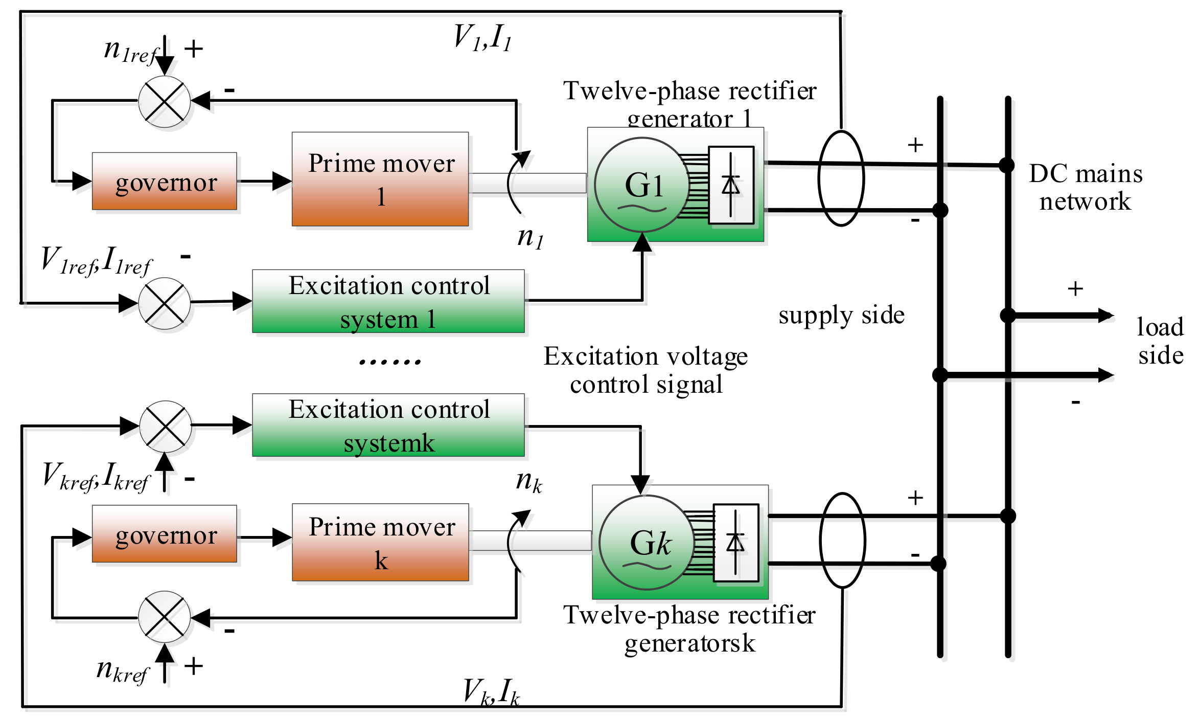
2. Twelve-Phase Rectifier Generator Power Supply System

2.1. System Topology

As shown in Figure 1, multiphase rectifier generators in parallel with the network provide the power supply of the entire ship’s equipment [25]. The twelve-phase rectifier generator set mainly consists of a rectifier generator, a trailing prime mover, and an excitation control system.
In this case, the multiphase rectifier generator consists of multiphase synchronous generators, an uncontrolled rectifier, and an excitation device. The basic working principle of the system is as follows [6,26]: the prime mover governor samples the closed-loop control of the motor speed, drags the twelve-phase rectifier generator to the working speed, and the alternating current (AC) issued by the synchronous generator is converted into direct current (DC) through the twenty-four pulsed-wave uncontrolled rectifier and then connected to the grid in parallel. The excitation control system realizes the voltage regulation of different units, a stable parallel connection, and output power equalization by adjusting the excitation current of corresponding generators.

2.2. Generator Rectifier Bridge Connection
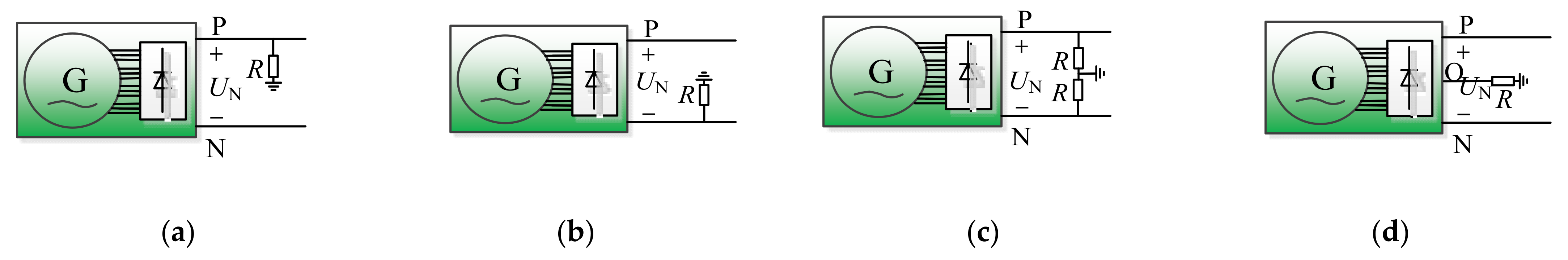
A multiphase synchronous generator generally consists of four sets of independent Y-shaped connections of three-phase AC windings, with each set of AC windings and a three-phase rectifier bridge unit being connected to the four sets of rectifier bridges through flexible series-parallel mixing to form a twenty-four-pulse wave rectifier output. As shown in Figure 2 [27], the rectifier bridge output can be “four parallel”, “four series”, or “two parallel and two series”, with a total of six types of connection combinations, and can achieve a reduction in the generator stator winding voltage at the same time to improve the grid voltage level or lead to the neutral point of the DC output, in order to facilitate the load side of the three-level propulsion inverter and other equipment voltage control [28,29]. It can be seen that the rectifier coupling methods (b), (c), and (f) can lead out the DC neutral point directly, but the other three coupling methods need to construct the DC neutral point with additional balancing resistors and other components at the DC output before it can be led out.

3. Grounding Design

Reasonable grounding design is the basis for the normal operation and ground fault diagnosis of power systems [30]. A multiphase rectifier generator power system, to carry out the grounding scheme (Figure 3) design, needs to comprehensively consider the coupled effects of fault characteristic changes on the AC and DC sides [31].

3.1. Selection of Grounding Method

Depending on whether the system is grounded or not and the selected dielectric path, it can be classified in four ways: ungrounded, directly grounded, resistance grounded, and resonant grounded [32,33]. The common application scenarios and main advantages and disadvantages of the different grounding forms are as follows:
1.
Ungrounded method:
The ungrounding method belongs to the small-current grounding method, and this grounding method is more often used in the traditional low-voltage alternating current (AC) power system [34,35], such as when a single ground fault occurs in the system. The fault current is generated only by the line cable capacitance to ground, and the system can continue to operate at this time [36,37]. The disadvantage is that it is difficult to detect the fault [38].
2.
Direct grounding:
The direct grounding method is a high-current grounding method, which is widely used in land-based, high-voltage power systems [39,40]. Since the fault current is too large when a ground fault occurs in this type of system, the fault line must be removed quickly. As a result, the system power supply continuity is poor, and it is easy to cause regional power losses [41].
3.
Resistance grounding:
According to the size of the grounding resistance value, it can be divided into high-resistance grounding system and low-resistance grounding system [42]. The rectification calculation of the grounding resistance value is the core of it, which can effectively limit the system fault current and voltage, makes it easy to detect faults, and the system can continue to operate when there is a single grounding fault. Therefore, the continuity of power supply is good, and it is widely used in scenarios such as ship medium-voltage power systems [43,44]. The disadvantage is that the formation of a grounding resistance loop produces some losses if other grounding points exist in the system [45].
4.
Resonant grounding:
Resonant grounding means that the system is grounded via an arcing coil (reactor with an air gap core), inducing magnetic field changes to generate inductive currents to compensate and offset the capacitive currents generated by the distributed capacitance of the faulted line to ground. Therefore, it is suitable for power systems with long transmission lines [46]. The disadvantage is that the size of the arcing coil is usually large, and the system distribution parameters are usually difficult to identify, resulting in difficulties in the fine tuning of the coil inductance value [47].
In addition to the above grounding methods, according to different application scenarios, there are capacitor grounding, reactance grounding, and other methods, and some scholars have also proposed a combination of grounding and other methods [48,49]. Considering a comprehensive comparison of multiple perspectives, such as simplicity and economy, continuity of power supply, and ease of fault detection, it is preferable to adopt the high-resistance grounding method for the medium-voltage DC power system of a ship [50].
The grounding methods are compared in Table 1.

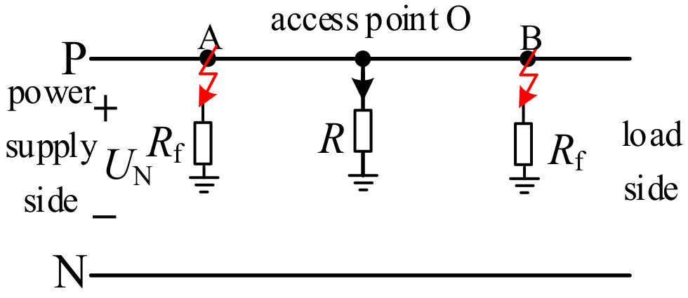
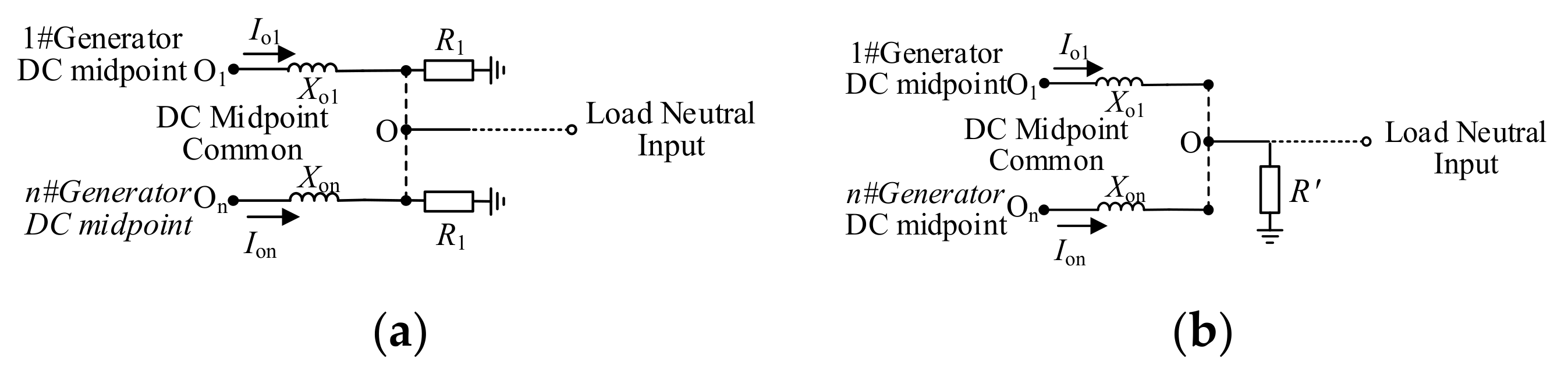
3.2. Selection of Grounding Location

AC-DC hybrid power systems are usually selected to have a single effective grounding method, “AC side grounding only” or “DC side grounding only”, in order to avoid the formation of interference circuits through multiple grounding points for different electrical networks [32]. While limiting the system fault current, the harmonics derived from the grounding side are introduced into the earth through the grounding line, thus making the output power quality more stable and reliable.
For the multiphase rectifier generator, the following disadvantages exist if AC side grounding is used: (1) the four sets of the three-phase windings of the generator are connected together through the grounding circuit, and they are no longer independent of each other, so it is easy to generate a loop current between different windings. At the same time, any one set of winding failure may affect the other winding normally working from the source to reduce the reliability of the system power supply; and (2) when the system ground fault current is large, or due to repeated arcing, generates a large over-voltage, through the grounding circuit, it is easy to directly damage the generator winding.
A multiphase rectifier generator can be used for DC output side grounding. It can be divided into four ways: positive grounding, negative grounding, constructing neutral grounding, and DC midpoint lead grounding [50].
As shown in Figure 4, regardless of the grounding method, the voltage between the positive and negative poles of the DC output remains unchanged. If the ground electrode is positive and affected by the reference ground potential, the positive electrode potential is 0, then the potential of the non-ground electrode (negative electrode) to ground is -UN; if the ground electrode is negative, affected by the reference ground potential, and the negative electrode potential is 0, then the potential of the non-grounded electrode (positive electrode) to ground is UN. Therefore, the rated working withstanding voltage of non-grounding pole line cables and hanging equipment cannot be lower than UN. In addition, when a unipolar ground fault occurs on the DC output side of the generator, if the fault point and the grounding point appear on the same pole busbar, as shown in Figure 5, whether the fault location occurs at A or B, the fault point and the grounding point O will not form a loop, so the current flowing through the ground resistance R has almost no change and it is difficult to determine whether the fault occurs by detecting the parameter change in the current there.
Neutral grounding by the means of an equivalent resistor is suitable for multiphase rectifier generators where the DC midpoint is not drawn out. When the grounding methods in Figure 4c,d are used, affected by the reference ground potential, the DC midpoint potential is 0, the positive electrode to ground potential is UN/2, and the negative electrode to ground potential is –UN/2, which greatly reduces the insulation requirements of DC line cables and network hanging equipment compared to the unipolar grounding method. At the same time, if a ground fault occurs at any pole of the DC output side of the generator, a current loop can be formed between the fault point and the grounding point through the earth, which facilitates the detection of ground faults. In addition, due to the grid DC neutral point construction or direct lead, it can also effectively reduce the three-level propulsion inverter and other medium-voltage power equipment DC side voltage control link.

3.3. Ground Resistance Calibration

The naval power station unit generally consists of two or more multiphase rectifier generator sets, with the DC side of each generator being grounded close to the ground through an independent resistor R1. In order to meet the neutral input requirements of medium-voltage loads, as shown in Figure 6, the DC midpoint of n generators is constructed directly by shorting the cable to the midpoint common O. At this point, the grounding resistance of the system can be equated to a set of resistors R′ and R′ = R1/n.
Because the DC midpoint terminal voltages of different units are not exactly the same, a loop current will be formed through the DC midpoint shorting [51]. As the load impedance characteristics are determined, the system power output is not affected by the DC midpoint loop current between the units, and the main influencing factor on the size of the DC midpoint loop current value of the system is the distribution resistance parameter of the generating unit itself and its neutral point connecting cable. Therefore, the impedance of the connecting line between the DC midpoints of the units can be increased to suppress the loop current by adding a resistance R2 before the DC midpoint parallel point of the units, as shown in Figure 7.
If Rng is used to denote the equivalent grounding resistance of the DC midpoint of a single generating unit, Rsg denotes the grounding resistance of the DC side of the system and Ro denotes the connection resistance between the DC midpoints of two units, and if the DC midpoint cable impedance of the generating unit Xon is ignored, then the expressions for Rng, Rsg, and Ro are as follows:
R ng = R 1 n + R 2 R sg = R 1 + R 2 n R o = 2 R 2  
From Equation (1), it can be seen that both Rng and Rsg are positively correlated with the R1 and R2 resistance values, and Ro is only correlated with R2. Obviously, the larger R2 is, the smaller the DC midpoint loop current between the units is, but incidentally, if Rng and Rsg become larger, the smaller the system damping is, which increases the risk of the possibility of the instability of the system with short-circuit faults [50]. China’s electric power industry standard DL/T 620-1997 [52] “overvoltage protection and insulation matching of AC electrical devices” stipulates that the ground fault current of a high-resistance grounding system should be less than 10 A. Referring to the relevant standards, R1 and R2 should be selected as appropriate values according to the number of system units.
A multiphase rectifier generator power system exists as a single machine and multiple machines in parallel and other operating conditions. If the number of generator sets operating in the system is m (mn) and the point connection in the DC of each generator set remains unchanged, then the system DC side grounding resistance Rng= R1/n + R2/m.

4. Ground Fault Detection and Localization

There are various types of ground faults. On the AC side, these can include single-phase, two-phase, and three-phase ground faults. On the DC side of the power distribution lines, you may encounter single-pole ground faults and pole-to-pole short-circuit faults caused by multiple grounding points [32,53]. When single-phase ground faults occur on the AC side and single-pole ground faults occur on the DC side, although the system can operate briefly, it is crucial to promptly determine the type and location of the fault to ensure the survivability of the ship. Since the theoretical framework for AC ground fault detection technology is more mature, this paper primarily focuses on research related to the detection and localization of single-pole ground faults on the DC side.

4.1. System Distributed Capacitance Calculation

Distributed capacitance parameters not only impact grounding system design, but also directly influence fault characteristics, including variations in voltage and current. Therefore, it is essential to calculate the system’s distributed capacitance to provide precise input parameters for grounding fault detection and localization.
Distributed capacitance on the AC side.
In a multiphase rectifier generator unit, due to the nearly direct connection between the synchronous generator output and the uncontrolled rectifier, we can neglect the distributed parameters of the connecting cables in between. Consequently, the distributed capacitance on the AC side of the unit primarily resides in the AC generator.
The distributed capacitance value in traditional steam turbine generators can be calculated using the empirical formula Cg1 = KλμL1/11.865d1 [54], where K is the correction factor, λ and L represent the number of stator slots and length, respectively, and μ and d stand for the periphery of the conductors within the slots and insulation thickness.
Reference [55] suggests that, if the insulation gap between the stator winding and the stator core is uniformly distributed with a spacing of ‘d’, as shown in Figure 8, then it can be approximated that the stator winding and stator slots are equivalent to two parallel plates. With a uniform distribution of insulation material in the gap between the plates and the insulation layer of the stator winding, the distributed capacitance of the generator stator winding, Cg2, can be expressed using Equation (2):
C g 2 = ε m [ 2 ( h d ) + ( l 2 d ) ] L 4 π k d
In Equation (2), where λ represents the total number of slots in the generator, h is the stator slot height, l is the stator slot width, and L2 is the length of the stator core. Additionally, d and ε denote the insulation thickness of the stator winding and the relative dielectric constant, respectively.
Distributed capacitance on the DC output side.
In shipboard power systems, power is distributed throughout the entire vessel via DC cables. Therefore, the distributed capacitance of DC cables cannot be ignored [56,57]. In the case of a twelve-phase rectifier generator, the distributed capacitance on the DC output side is primarily concentrated in the DC busbar cable. According to marine cable standards, there is typically a metal shielding layer between the inner insulation layer and the outer sheath, as shown in Figure 9. The cable conductor has a radius of r1 and the insulation layer thickness is r2.
From Gauss’s magnetic flux theorem, we can deduce the formula for calculating the distributed capacitance (Cc) of DC cables as follows [58,59]:
C c = 2 π ε i ln r 2 / r 1
In Equation (3), ε i = ε ε 0 ; ε i represents the vacuum permittivity and ε represents the relative permittivity of the insulation material.

4.2. Ground Fault Characteristic Analysis

In the event of a single-pole ground fault in a power system, there will be rapid changes in voltage, current, and other state parameters, and it may even lead to the generation of direct current common-mode fluctuations and non-characteristic harmonics [32]. Furthermore, due to environmental influences, there is a possibility of variation in the transient resistance at the ground fault point, which further complicates the fault detection [60].
Based on the time scale, the changes in system behavior when a single-pole ground fault occurs can be divided into two stages: transient and steady state [50]:

4.2.1. Transient Stage

As shown in Figure 10, when a single-pole ground fault occurs in the DC power grid, the fault circuit exhibits underdamped behavior due to the very low line impedance. The presence of cable distribution capacitance causes the current at the fault point and the ship’s hull to rise rapidly, resulting in an oscillatory fault current with RLC circuit characteristics. When the system ground resistance or ground distribution capacitance is larger, the system damping is smaller, the oscillation amplitude of the system bus voltage after the ground fault occurs, and the longer it takes to stabilize. Clearly, due to the short discharge time of the system fault lines (within milliseconds), the available window for transient fault data changes is brief, necessitating high-sensitivity requirements for fault information acquisition devices.

4.2.2. Steady–State Stage

Due to the relatively shorter cable lengths in a ship’s DC power grid compared to those of land-based grids, and the smaller distributed capacitance of the cables, if there are no other fault-related effects, when the system’s distributed capacitance and the capacitance of the connected DC-side equipment release their stored energy rapidly, the system gradually enters a stable fault operating state. At this point, the current flowing into the ground (ship’s hull) from the fault point also approaches a stable value.
In the field of simulation and mathematical modeling research, Reference [50] constructed a simulation model for a medium-voltage DC comprehensive power system. They conducted simulations to calculate the changes in system voltage and current under various operating conditions. They qualitatively analyzed the influencing factors on ground fault characteristics and the mutual interactions between ground faults at different network levels.
Additionally, Reference [61] modeled a twelve-phase rectifier generator as twenty-four pulse-controlled rectifiers powered by four sets of three-phase ideal voltage sources. They analyzed the commutation and conduction patterns of the rectifiers and established a dynamic mathematical model for a DC single-pole 72 ground fault using switch functions and harmonic balance principles. However, this reference did not account for the dynamic excitation control characteristics of the AC generator during the transient changes in ground fault conditions.

4.3. Fault Detection and Localization

Currently, the research on ground fault detection and localization in multiphase rectifier generator power systems for ships in China is relatively limited. Reference [62] attempted to detect the fault pole by monitoring the current direction flowing through the DC midpoint grounding resistor of a twelve-phase rectifier generator. An additional set of resistors was connected in parallel to the grounding resistor circuit. When a ground fault was detected, fault localization and protection were achieved by comparing the difference in current between the two phases through the closure of the circuit breaker in series with the additional grounding resistor. They built a test system to validate this approach, which is simple in terms of principle and operation. However, this method has limitations, as it does not consider system distributed parameters or transient resistance ground faults. Moreover, its applicability under an increased system scale and quantity requires further research and validation. Additionally, the validation of research outcomes related to ground fault detection and localization is primarily achieved through semi-physical simulations or low-power prototypes. There is currently no reported news on high-power platform testing in this regard.
Research on ground fault detection and localization in land-based DC power grids and DC microgrids is relatively mature and has yielded some theoretical and practical achievements. Some of the research approaches in this field can provide valuable insights. In land-based DC transmission lines, fault detection and localization are primarily conducted using the traveling wave method [63,64]. Collection devices are installed at certain intervals along the transmission lines, and fault types and locations are identified by recognizing fault voltage or current traveling waves. In theory, this method is not affected by the parameters of the transmission lines, but it requires a high signal sampling frequency and faces challenges such as a difficulty in recognizing traveling wave fronts, a poor interference resistance, and synchronization positioning errors. In recent years, the development of intelligent algorithms has provided new avenues for ground fault diagnosis in high-voltage DC transmission systems.
Direct current microgrids and medium-voltage DC comprehensive power systems exhibit a greater degree of similarity, particularly with respect to relatively shorter line lengths. When reviewing ground fault localization methods in DC microgrids, they can primarily be categorized into two types based on the source of fault detection and signal analysis.

4.3.1. Passive Signal Method

Basic Principle: installing voltage and current sensors at critical nodes in the power system to continuously monitor real-time changes in the system’s own state signals. This method analyzes and determines the presence of ground faults and their specific locations. Examples include leakage current detection [65] and impedance methods [66,67]. The advantage of this approach is that it does not affect the normal operation of the system, making online fault monitoring convenient. However, the drawback is that it requires a high precision in collecting data on system state changes, and the cost of equipment installation can be substantial.

4.3.2. Active Signal Method

Basic Principle: based on the topology of the power grid system, select the appropriate node location to arrange the signal injection and signal acquisition equipment, respectively. By injecting signals (primarily low-frequency) into the system and processing the characteristic signals of faults through techniques such as filtering transformations [68,69], morphological filtering [70,71], wavelet transformations [72,73], S-transform [74], and Hilbert–Huang transform [75], it is possible to analyze and determine the location of the faulted circuit. The advantage of this method is its ability to overcome the influence of parameters, like system distributed capacitance, on detection and localization results. However, the drawback is that the algorithm is relatively complex, and signal injection into the system can be considered as a form of interference. Careful consideration is required for factors such as signal energy and frequency to avoid compromising the system operational safety.
A comparison of various fault detection methods is presented in Table 2.

5. Conclusions

Currently, the practical grounding design often uses various grounding methods, such as no grounding, direct grounding, and resistance grounding, using only AC or only DC grounding. This approach carries the risk of damaging the motor windings and impeding the identification of faults. On the other hand, using the DC midpoint without leading out the structure facilitates real-time fault monitoring. Although each method has its benefits, there are areas for improvement. The demand for ground fault detection is increasing, with both passive and active signal methods being used. The passive method is convenient for online fault detection, but requires a high accuracy. The active method can overcome parameter influences like distributed capacitance, but its algorithm is relatively complex and can affect system security.

6. Foresight

With a ship’s functional requirements and the continuous development of integrated power technology, the system capacity becomes larger and pulse loads on board the ship application will be the future development trend. Therefore, the power grid system will be in the short-time repetitive non-periodic transient limit operation state, and any fault-induced fluctuation and impact of the power grid may affect the safe operation of the system, so the design of the system grounding and ground fault detection and localization technology research needs will be more intense. The outlook is as follows:
  • Carry out an analysis of the multi-point grounding characteristics of a medium-voltage DC integrated power system, further optimize the system network topology and grounding scheme design, limit the magnitude of ground fault voltage and current fluctuations, and facilitate the design and specific implementation of fault detection, location, and protection.
  • Based on information perception, artificial intelligence, and other advanced technologies, explore and research the grounding fault detection and location methods applicable to the medium-voltage DC integrated power systems of ships, which can realize online rapid location and minimize regional isolation and cooperative protection, reducing the impact on the system. At the same time, combined with the energy management system, it can intelligently optimize and regulate the integrated power system in multiple time scales and multiple target dimensions to ensure the system’s economy, mobility, and security.

Author Contributions

Conceptualization, H.H. and F.M.; data curation, F.M.; formal analysis, H.H.; investigation, W.Z.; methodology, L.F.; project administration, H.H.; resources, H.H.; software, W.Z.; supervision, H.H.; validation, H.H., F.M. and C.L.; visualization, F.M.; writing—original draft, F.M.; writing—review and editing, L.F. All authors have read and agreed to the published version of the manuscript.

Funding

This research was funded by the National Key R&D Program of China (2022YFE0125200), the National Natural Science Foundation of China (51975426), the Hubei Provincial Key R&D Program of China (2021BAA018, 2022BAA062), and the Wuhan Knowledge Innovation Program of China (2022010801010305).

Data Availability Statement

Not applicable.

Conflicts of Interest

The authors declare no conflict of interest.

References

  1. Ma, W. AC-DC power integration techniques. Eng. Sci. 2002, 4, 53–59. [Google Scholar]
  2. Sun, Y.; Wang, X.; Yin, Z. Harmonic Characteristics of AC/DC Converters and Their simplified Models. Autom. Electr. Power Syst. 2012, 36, 51–56. [Google Scholar]
  3. Wu, B.; Zhang, X.; Chen, L.; Xu, G.; Li, G. Researches on Influence of Grounding Mode of 12-Phase Generator with Rectifier Load on DC Overvoltage. Trans. China Electrotech. Soc. 2019, 34 (Suppl. 1), 321–326. [Google Scholar]
  4. Jordan, S.; Apsley, J. Open-circuit fault analysis of diode rectified multiphase synchronous generators for DC aircraft power systems. In Proceedings of the 2013 IEEE International Electric Machines & Drives Conference (IEMDC), Chicago, IL, USA, 12–15 May 2013; IEEE: New York, NY, USA, 2013; pp. 926–932. [Google Scholar]
  5. Zhang, X. Study on Fault Operation of Twelve-Phase Rectifier Generator System; Qingdao University: Qingdao, China, 2019. [Google Scholar]
  6. Fu, L.; Liu, L.; Wang, G.; Ma, F.; Ye, Z.; Ji, F.; Liu, L. The research progress of medium voltage DC integrated power system in China. Chin. J. Ship Res. 2016, 11, 72–79. [Google Scholar]
  7. Ma, W. Typical applications of power electronics in naval power systems. J. Electrotech. 2011, 26, 1–7. [Google Scholar]
  8. Ma, W. Reflections on the Compound Development of Ship Electrification and Informatization. J. Nav. Eng. Univ. 2010, 22, 1–4. [Google Scholar]
  9. He, Y.; Wen, Z. Power System Analysis; Huazhong University of Science and Technology Press: Wuhan, China, 2002. [Google Scholar]
  10. Wang, B.; Cai, L.; Tong, X.; Li, H.; Wang, H.; Liu, C.; Zhang, H.; Wang, L. Analysis of asymmetric short-circuit faults in neutral ungrounded systems. Power Syst. Prot. Control 2017, 45, 98–104. [Google Scholar]
  11. Guo, Q.; Wu, T. A review of fault routing methods for small-current grounding systems. Power Syst. Prot. Control 2010, 38, 146–152. [Google Scholar]
  12. Liu, J.; Zhang, Z.; Zhang, X.; Du, H.; Shi, J. Single phase to ground fault location based on distribution automation system. Autom. Electr. Power Syst. 2017, 41, 145–149. [Google Scholar]
  13. Dai, Z.; Ge, H.; Yan, S.; Jiao, Y.; Chen, X. Analysis of the impact of grounding mode on fault characteristics in flexible DC distribution networks. Grid Technol. 2017, 318–329. [Google Scholar]
  14. Yu, X.; Xiao, L. An overview of fault identification and location technology for DC distribution networks. Adv. Technol. Electr. Eng. Energy 2019, 38, 56–66. [Google Scholar]
  15. Chen, H.; Tian, X.; Gao, C.; Zheng, S.; Yan, C. Research overview on Fault Location for DC Microgrid. Guang Dong Electr. Power 2019, 32, 44–51. [Google Scholar]
  16. Zeng, X.; Wang, Z.; Yu, K.; Peng, H.; Zhuo, C.; Zhou, D. Arc Suppression Device for Actively Reducing Grounding Fault Phase Voltage Based on Phase Power Supply Feedback in Distribution Network and Its Application. High Volt. Eng. 2022, 48, 3356–3366. [Google Scholar]
  17. Flourentzou, N.; Agelidis, V.G.; Deetriades, G.D. VSC-based HVDC Power Transmission Systems: An Overview. IEEE Trans. Power Electron. 2009, 24, 592–602. [Google Scholar] [CrossRef]
  18. Li, X.; Fan, C.; Wang, G.; Jin, S. DC-side Fault Characteristics and Grounding Mode of Hybrid AC/DC Distribution Network with Two-terminal Power Supply. Autom. Electr. Power Syst. 2022, 46, 161–169. [Google Scholar]
  19. Jia, W.; Cao, S. Parameter optimization design of combination-type grounding mode for large-sized hydropower units. Electr. Power Autom. Equip. 2022, 42, 79–85. [Google Scholar]
  20. Salomonsson, D.; Soder, L.; Sannino, A. Protection of low-voltage DC microgrids. IEEE Trans. Power Deliv. 2009, 24, 1045–1053. [Google Scholar] [CrossRef]
  21. Tian, J.; Yao, L. Analysis of the Influences of Small Resistance Grounding on Distribution Network Reliability. Electr. Eng. 2022, 23, 121–122/126. [Google Scholar]
  22. Zeng, R.; Zhao, Y.; Zhao, B.; Zhong, Q.; Tong, Y.; Yuan, Z.; Yu, Z.; Zhao, Z.; Li, Y.; Chen, J. Research and application prospects of technologies for DC power distribution. Proc. CSEE 2018, 38, 6791–6801. [Google Scholar]
  23. Wang, Y.; Fu, Y.; Zeng, Q.; Song, Y. Review on key techniques for fault protection of flexible DC grids. High Volt. Eng. 2019, 45, 2362–2374. [Google Scholar]
  24. Nian, H.; Kong, L. Review on Fault Protection Technologies of DC Microgrid. High Volt. Eng. 2020, 46, 2241–2254. [Google Scholar]
  25. Ye, Z.; Fang, M.; Ma, F. The principle of generator units switching on/off in naval vessel integrated power system. Ship Sci. Technol. 2012, 34, 49–52. [Google Scholar]
  26. Ji, F.; Fu, L.; Ye, Z. Experimental research of MVDC parallel operation generator sets for vessel integrated power systems. J. Nav. Univ. Eng. 2017, 29, 11–16. [Google Scholar]
  27. Guo, Y.-J.; Wang, D.; Yi, X. Currents of sudden DC-side short circuit of multiphase generator-rectifier system with series-parallel connection. Electr. Mach. Control 2017, 22, 77–92. [Google Scholar]
  28. Hu, L.; Xiao, F.; Lou, X.; Ai, S.; Gao, S. Research on output voltage abnormal voltage pulses of three-level H-bridge inverter base on cascaded carrier modulation. Proc. CSEE 2019, 39, 266–276. [Google Scholar]
  29. Gao, Z.; Li, Y.; Ge, Q.; Zhao, L.; Wang, K. Improved phase opposition disposition pulse width modulation strategy for three-level neutral point clamped converter. Trans. China Electrotech. Soc. 2021, 36, 831–842. [Google Scholar]
  30. Xue, S.; Li, Z.; Liu, C.; Jia, C.; Wang, J.; Li, F.; Zhu, X. Review of DC Microgrids Grounding and Study on Protection Methods Based on Control and Protection Cooperation. High Volt. Eng. 2020, 46, 2255–2268. [Google Scholar]
  31. Dai, Z.; Zhu, H.; Su, H.; Wang, Z. Sequence Component Networks in Hybrid AC/DC Power Systems and Its Application in Analysis on Influence of CDSM-MMC DC-Side Short Fault on AC Side. Power Syst. Technol. 2018, 42, 3583–3593. [Google Scholar]
  32. Howar, F. Designing All Electric Naval Surface Ship; Navy: Arlington, VA, USA, 2008. [Google Scholar]
  33. Gustafson, R.; Albertson, V. Neutral-to-Earth Voltage and Ground Current Effects in Livestock Facilities. IEEE Trans. Power Appar. Syst. 1982, 9, 2009. [Google Scholar]
  34. Burke, J.; Marshall, M. Distribution system neutral grounding Transmission and Distribution Conference and Exposition. IEEE PES 2001, 28, 10–13. [Google Scholar]
  35. Cao, Z.; Guo, X.; Jia, X. Study on grounding mode of distribution network. North China Electr. Power 2007, 51–54. [Google Scholar]
  36. Javed, W.; Chen, D.; Farrag, M.E.; Xu, Y. System configuration, fault detection, location, isolation and restoration: A review on LVDC microgrid protections. Energies 2019, 12, 1001. [Google Scholar] [CrossRef]
  37. Qi, Z.; Tian, J.; Xue, Y.; Cai, Z.; Xu, B. Analysis of Power Frequency Electrical Quantity and Line Selection Applicability for Two-Piont Grouding Faults Occurring on Different Phase in Isolated Neutral System. Trans. CN Electr. Society 2023, 38, 3539–3551. [Google Scholar]
  38. Pan, B.; Guan, T.; Gui, X.; Xue, Y.; Guo, L. Characterization of high-resistance grounding faults in ungrounded systems and analysis of routing applicability. J. Power Syst. Autom. 2017, 56–63. [Google Scholar]
  39. Su, J. Research of neutral grounding modes in power distribution network. Power Syst. Prot. Control 2013, 41, 141–148. [Google Scholar]
  40. Liu, Y.; Wang, J.; Mi, H. Optimization research on neutral grounding mode of 10 kV distribution network. High Volt. Technol. 2015, 3355–3362. [Google Scholar]
  41. Mohammadi, J.; Ajaei, F.B.; Stevens, G. Grounding the DC microgrid. IEEE Trans. Ind. Appl. 2019, 55, 4490–4499. [Google Scholar] [CrossRef]
  42. Ye, Y.; Wang, S.; Xie, M.; Cai, X.; Xu, B.; Wei, L. Study on the Control method of High Impedance faults in the neutral Via Arc Suppression Coil Paralleled with A Low Resistance Grounded system. Power Syst. Prot. Control 2021, 49, 181–186. [Google Scholar]
  43. Chen, L.; Li, G.; Zhang, X. Resistant Parameter Calculation for Shipboard Medium Voltage Neutral Grounded Generator. Mar. Electr. Electron. Eng. 2015, 35, 9–12. [Google Scholar]
  44. Wu, B.; Zhang, X.; Zhang, C.; Liu, S.; Xu, G. Influence of Grounding Mode of 6-phase Generator with Rectifier-Load on Harmonics in Shipboard Medium Voltage Power Systeme. Power Syst. Prot. Control 2019, 47, 92–98. [Google Scholar]
  45. Long, Y.; Ouyang, J.; Xiong, X.; Ma, G.; Yang, M. Protection principle of single-phase high resistance fault for distribution network based on zero-sequence power variation. Trans. China Electrotech. Soc. 2023. early view. [Google Scholar] [CrossRef]
  46. Shao, W.; Liu, Y.; Cheng, Y.; Zhang, Z.; Chen, C. Fault line selection method of grounding fault with high resistance in resonant grounding system based on intensive zero-sequence impedance characteristics. Electr. Power Autom. Equip. 2021, 41, 120–126. [Google Scholar]
  47. Liu, B.; Zeng, X.; Zhang, H.; Ma, H. Optimal control method for accurate and fast suppression of unbalanced zero-sequence voltage and voltage arc suppression full compensation. Trans. China Electrotech. Soc. 2022, 37, 645–654. [Google Scholar]
  48. Ye, Y.; Wang, S.; Huang, T.; Wei, L. Study on Grounding Mode of Neutral Point through Arc Suppression Coil in Parallel with Median Resistance. J. Electr. Eng. 2021, 16, 159–165. [Google Scholar]
  49. Zhang, B.; Hong, Y. Analysis on the Neutral Point Grounding via Arc Suppression Coil Paralleled Controllable Small Resistance. Electr. Saf. Technol. 2022, 24, 21–24. [Google Scholar]
  50. Zhang, Q. Research on Ground Fault Detection and Localization Method of Medium Voltage DC Integrated Power System; Naval Engineering University: Wuhan, China, 2015. [Google Scholar]
  51. Huang, H.; Ma, F.; Fu, L.; Zhang, X.; Jing, C. DC Neutral Point Circulating Current Characteristics and Suppression Method of Twelve-phase Rectifier Generator Parallel Power Supply System. Trans. China Electrotech. Soc. 2022, 37, 1760–1767. [Google Scholar]
  52. DL/T 620-1997; Overvoltage Protection and Insulation Matching of AC Electrical Devices. CSIC-DL: Madrid, Spain, 1997.
  53. Xia, Y.; Wan, Y.; Xi, H. Analysis of line over-voltage protection accident caused by multi-point grounding of PT secondary circuit. Electr. Eng. 2021, 94–98. [Google Scholar]
  54. Liu, S. Research on Neutral Grounding Method of Generator; Tianjin University: Tianjin, China, 2004. [Google Scholar]
  55. Wu, B.-X. Research on Grounding Method of Medium Voltage DC Power System of Ship; Naval Engineering University: Wuhan, China, 2019. [Google Scholar]
  56. Cao, S. Research Report on Neutral Grounding Technology of Power Supply System; China Shipbuilding Heavy Industry Corporation, 704 Research Institute: Shanghai, China, 2007. [Google Scholar]
  57. Borioli, E.; Brenna, M.; Faranda, R.; Simioli, G. Comparison between the Electrical capabilities of the cables used in LV AC and DC power lines. In Proceedings of the International Conference on Harmonics and Quality of Power, Lake Placid, NY, USA, 12–15 September 2004. [Google Scholar]
  58. Nie, D.; Luo, N. The Estimation on Distributed Capacitance of Middle-voltage Shipboard Power System. Mar. Electr. Electron. Eng. 2014, 34, 68–80. [Google Scholar]
  59. Wu, B.; Li, H.; Luo, N. Estimation of Medium Voltage Shore-to-Ship Power System Distributed Capacitance. Ship Electron. Eng. 2014, 34, 187–190. [Google Scholar]
  60. Li, C.; Zhao, C.; Xu, J.; Ji, Y.; Zhang, F.; An, T. A pole-to-pole short-circuit fault current calculation method for DC grids. IEEE Trans. Power Syst. 2017, 32, 4943–4953. [Google Scholar] [CrossRef]
  61. Li, C. Dynamic Modeling of DC Main Grid Grounded Short Circuit Characteristics of Shipboard Medium Voltage DC Integrated Power System; Naval Engineering University: Wuhan, China, 2019. [Google Scholar]
  62. Zhang, Q.; Fan, M.; Jiang, H. A Method of Grounding Fault Protection in DC Power System with Grounding Resistance. Mar. Electr. Electron. Eng. 2015, 35, 1–5. [Google Scholar]
  63. Ge, Y. New Relay Protection and Fault Ranging Principle and Technology; Xi’an Jiaotong University Press: Xi’an, China, 2007. [Google Scholar]
  64. Bai, T.; Zhang, B.; Dong, H. Application of traveling wave method in fault location and detection high voltage transmission line. Electr. Eng. 2020, 46–49. [Google Scholar]
  65. Qi, J.; Yang, G.; Luo, Z. Error analysis of phase difference magnetic modulation DC leakage current sensor. Autom. Instrum. 2018, 9, 149–152. [Google Scholar]
  66. Xue, S.; Lu, J.; Liu, C.; Fan, B.; Shi, Z.; Lian, J. Single-end fault ranging method for MMC-HVDC transmission system based on virtual line impedance. Grid Technol. 2019, 43, 2868–2875. [Google Scholar]
  67. Jia, K.; Dong, X.; Li, L.; Feng, T.; Bi, T. Distribution network fault ranging based on sparse voltage magnitude measurement. Grid Technol. 2020, 44, 835–845. [Google Scholar]
  68. Macedo, J.R.; Resende, J.W.; Bissochi, C.A.; Carlos, A.; Carvalho, D.; Castro, F. Proposition of an interharmonic-based methodology for high-impedance fault detection in distribution systems. IET Gener. Transm. Distrib. 2015, 9, 2593–2601. [Google Scholar] [CrossRef]
  69. Li, Y.; Meng, X.; Song, X. Application of signal processing and analysis in detecting single line-to-ground (SLG) fault location in high-impedance grounded distribution network. IET Gener. Transm. Distrib. 2016, 10, 382–389. [Google Scholar] [CrossRef]
  70. Shu, H.; Gong, Z.; Tian, X.; Dong, J.; Li, S. Singleline-to-ground fault line selection based on fault characteristic frequency band and morphological spectrum. Power Syst. Technol. 2019, 43, 1041–1048. [Google Scholar]
  71. Li, Z.; Liu, J.; Xi, Y.; He, Z.; Lv, J.; Long, X. Fault location method for distribution network based on transient waveform correlation. Autom. Electr. Power Syst. 2020, 44, 72–79. [Google Scholar]
  72. Tao, C.; Du, X.; Gao, F.; Wang, Y.; Yang, Q. Single-phase to ground fault location of hybrid transmission lines based on empirical wavelet transform. Power Syst. Prot. Control 2021, 49, 105–112. [Google Scholar]
  73. Zheng, W.; Zhang, F.; Li, W.; Lu, T. Single-phase ground fault location for EHV transmission lines based on dyadic wavelet transform. Electron. Des. Eng. 2021, 29, 115–118. [Google Scholar]
  74. Yang, Y.; Wu, H.; Tian, H. Single-ended intelligent fault location method for HVDC transmission lines. Proc. CSU-EPSA 2023, 35, 120–129. [Google Scholar]
  75. Deng, X.; Lin, Y.; Yu, H. Research on Cable Fault Location Based on Improved HHT. Mech. Electr. Inform. 2022, 82–85. [Google Scholar]
Figure 1. Schematic diagram of twelve-phase rectifier generator parallel power supply unit.
Machines 11 00985 g001
Figure 2. Equivalent topology of a twelve-phase rectifier generator: (a) quadruple parallel structure; (b) four-string configuration; (c,d) two-parallel-two-strings structure 1, 2; and (e,f) two-parallel-two-strings structure 3, 4.
Machines 11 00985 g002
Figure 3. Schematic diagram of common grounding methods: (a) ungrounded; (b) directly grounded; (c) grounding through resistance; and (d) grounding through arc suppression coil.
Machines 11 00985 g003
Figure 4. DC output side grounded through resistance: (a) positive grounding; (b) negative grounding; (c) constructing neutral grounding; and (d) DC midpoint lead grounding.
Machines 11 00985 g004
Figure 5. Grounding fault diagram of single machine grounding system.
Machines 11 00985 g005
Figure 6. DC neutral point grounding topology of generators parallel power supply system: (a) generator DC midpoint conventional grounding method and (b) equivalent system DC midpoint grounding.
Machines 11 00985 g006
Figure 7. Adding series resistance to DC neutral.
Machines 11 00985 g007
Figure 8. Equivalent diagram of estimating distributed capacitance of generator stator windings. Equivalent diagram of the distributed capacitance of the generator stator winding.
Machines 11 00985 g008
Figure 9. Diagram of cross-sectional structure of selected cables.
Machines 11 00985 g009
Figure 10. Voltage and current waveform of grounding fault [55]: (a) fault voltage waveform (positive polarity); and (b) fault current waveform.
Machines 11 00985 g010
Table 1. Comparison of advantages and disadvantages of different grounding methods.
NumberMethodsCostAdvantageDisadvantage
1UngroundedNoContinue to operate with single faultDifficult to detect the fault
2Directly groundedLowQuick fault removalPoor power supply continuity
3Resistance groundingAverageGood power supply continuityEnergy consumption during fault operation
4Resonant groundingVery HighLong line systemLarge volume and difficulty in parameter tuning
Table 2. Comparison of advantages and disadvantages of different fault detection methods.
MethodsCostAdvantageDisadvantage
Passive detection methodLeakage current detection, impedance methods et alHighMinimal impact on the power system, simple principle, and facilitates online fault monitoringRequires high precision in collecting data on system state changes
Active detection methodFiltering transformations, morphological filtering,
wavelet transformations,
S-transform, Hilbert–Huang transform et al.
LowOvercome the influence of system parameterEasy to affect the power system, algorithm complexity, and difficulty in achieving online fault monitoring
Disclaimer/Publisher’s Note: The statements, opinions and data contained in all publications are solely those of the individual author(s) and contributor(s) and not of MDPI and/or the editor(s). MDPI and/or the editor(s) disclaim responsibility for any injury to people or property resulting from any ideas, methods, instructions or products referred to in the content.

