

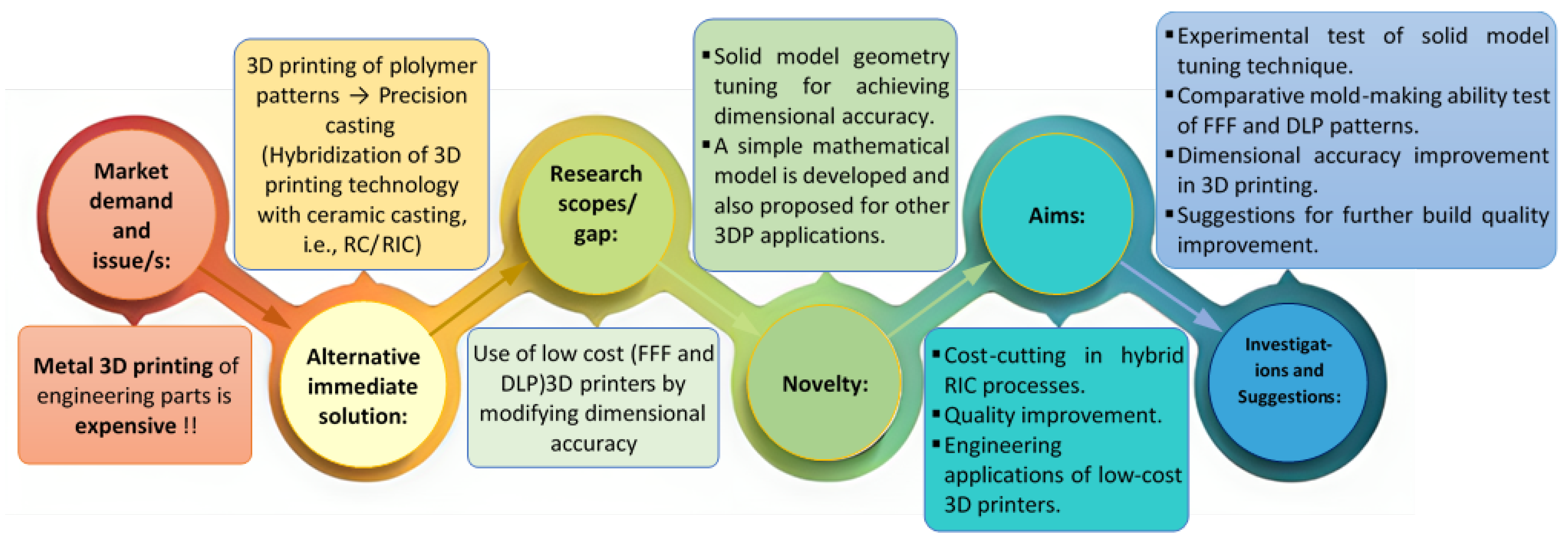
Enhancing Dimensional Accuracy in Budget-Friendly 3D Printing through Solid Model Geometry Tuning and Its Use in Rapid Casting


Abstract
:1. Introduction
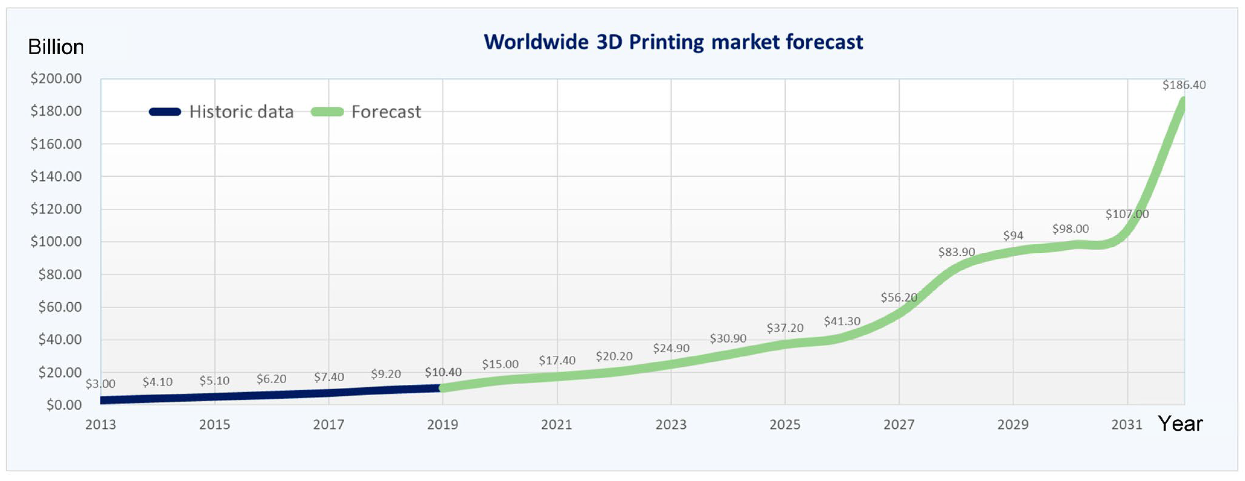
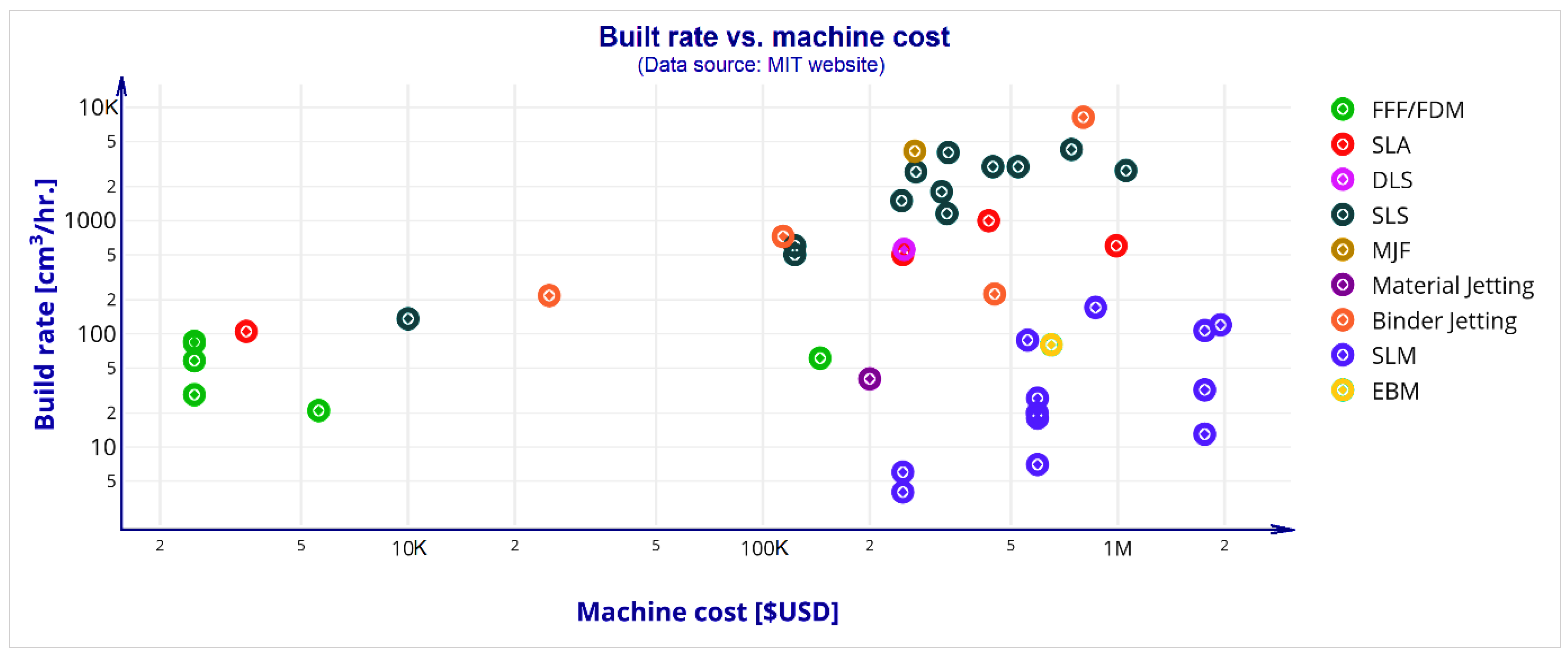
1.1. The 3D Printing Technology and Its Industrial Significance
1.2. Integration of 3DP in Rapid Casting in Industrial Contexts
- ▪
- Shape complexity: almost any degree of external complexity and a wide range of internal complexity can be achieved;
- ▪
- Freedom of alloy selection: super alloys, MMC, advanced materials, etc.;
- ▪
- ▪
- The availability of prototype and temporary tooling;
- ▪
- Reliability: demanding industries, including gas turbine engines, petroleum, chemicals, military, and medicine, have long relied on investment casting [27];
- ▪
- Wide range of applications: few grams to more than 300 kg.
1.3. Statement of the Research Objectives
- ▪
- To develop a solid model (1st phase) and 3DP by FFF and SLA (DLP) technology and measure the dimensional variations in X, Y, and Z directions.
- ▪
- Tuning/modifying first solid mode by adjusting dimensional variations (allowances) in X, Y, and Z directions and developing a modified solid model (second) and 3DP for dimensional accuracy improvement verification.
- ▪
- A modified solid model is used for pattern printing in the FFF and SLA (DLP) process and tested to make the same metallic parts in rapid casting.
- ▪
- Exploring the technical issues and remedial measure findings as the future scope of this work.
2. Materials and Methods
2.1. Three-Dimensional Printing Machine and Material Details
2.2. RC Mould Making and Material Details
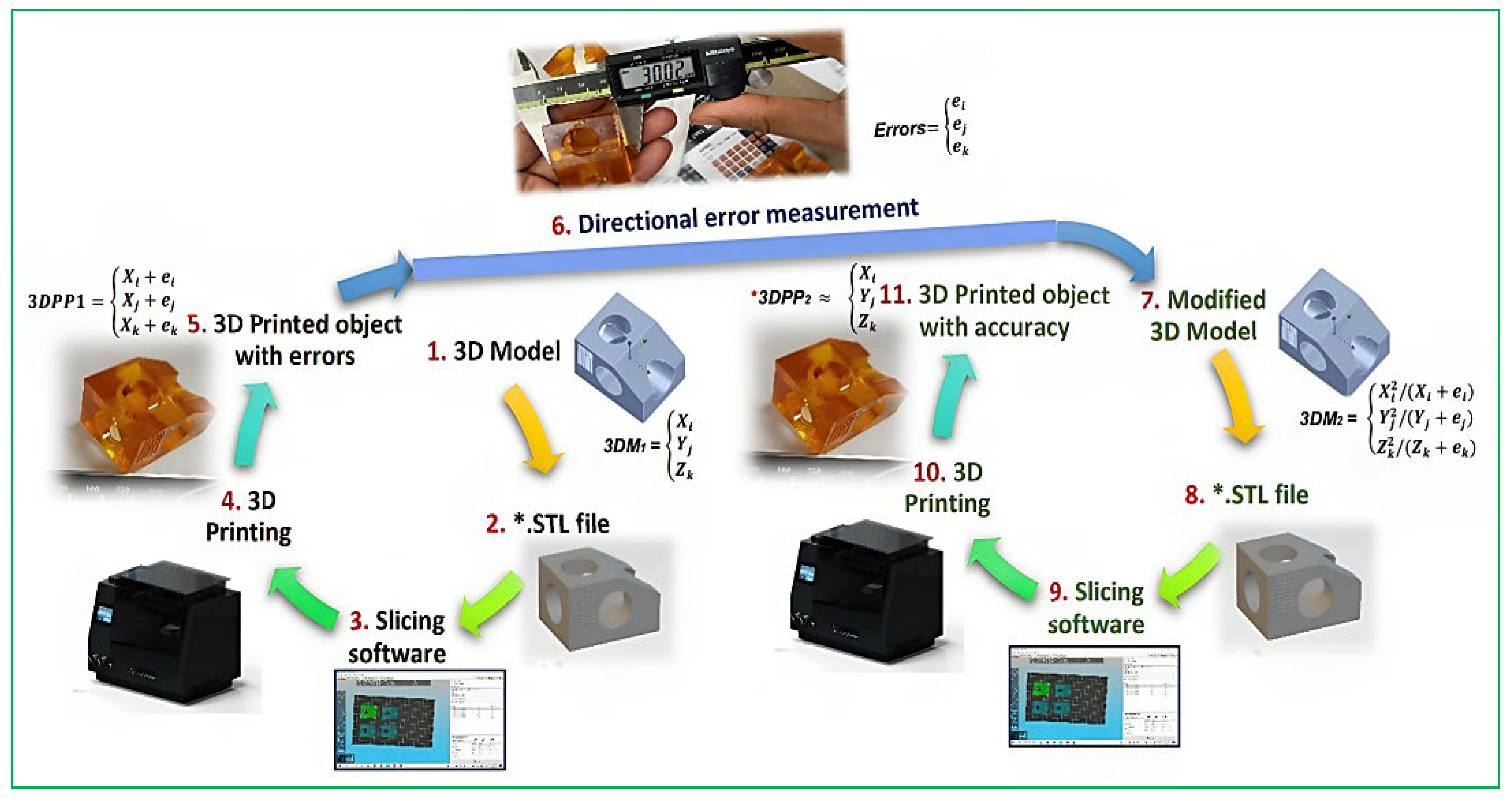
2.3. Techniques for Solid Model Geometry Tuning
The Error-Tuning Model
| Final product dimensions | Tuned 3D model dimensions |
2.4. Rapid Casting Test
3. Results and Discussions
3.1. Presentation of Empirical Data Showcasing Dimensional Accuracy before and after Geometry Tuning
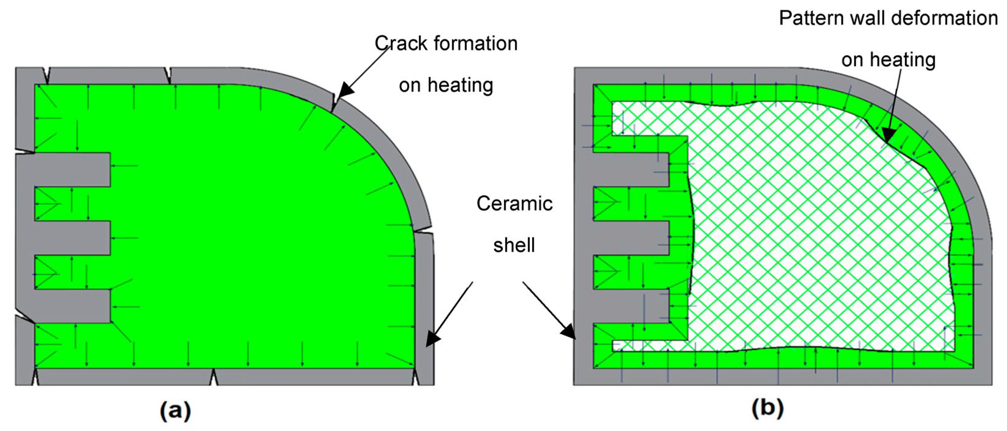
3.2. Observations in Rapid Casting
4. Conclusions
- ▪
- Highly complex parts that cannot be manufactured using other manufacturing processes can be effectively produced through direct metal 3D printing. For low- to medium-complexity metal parts, cost-effective production can be achieved through the RC/RIC process.
- ▪
- A substantial amount of research and investigation is crucial for the commercialisation of the RC/RIC process.
- ▪
- Affordable 3D printing (3DP) technologies, such as FFF or DLP processes, can potentially be leveraged for cost-effective engineering applications and the manufacturing of metal products using the RC/RIC route in job shop production houses through solid model tuning.
- ▪
- The proposed and experimentally tested mathematical model for solid model geometry tuning can be applied to other 3D printing methods to enhance the dimensional accuracy of 3D-printed products, making them compliant with engineering tolerances and suitable for various applications.
- ▪
- This study examines the ceramic mould-building capacity for rapid casting (RC) using medium-sized (4 to 10 cm) wax-made DLP patterns and PLA-made FFF patterns. The hollow interior of the FFF-based 3D-printed patterns facilitates successful RC.
- ▪
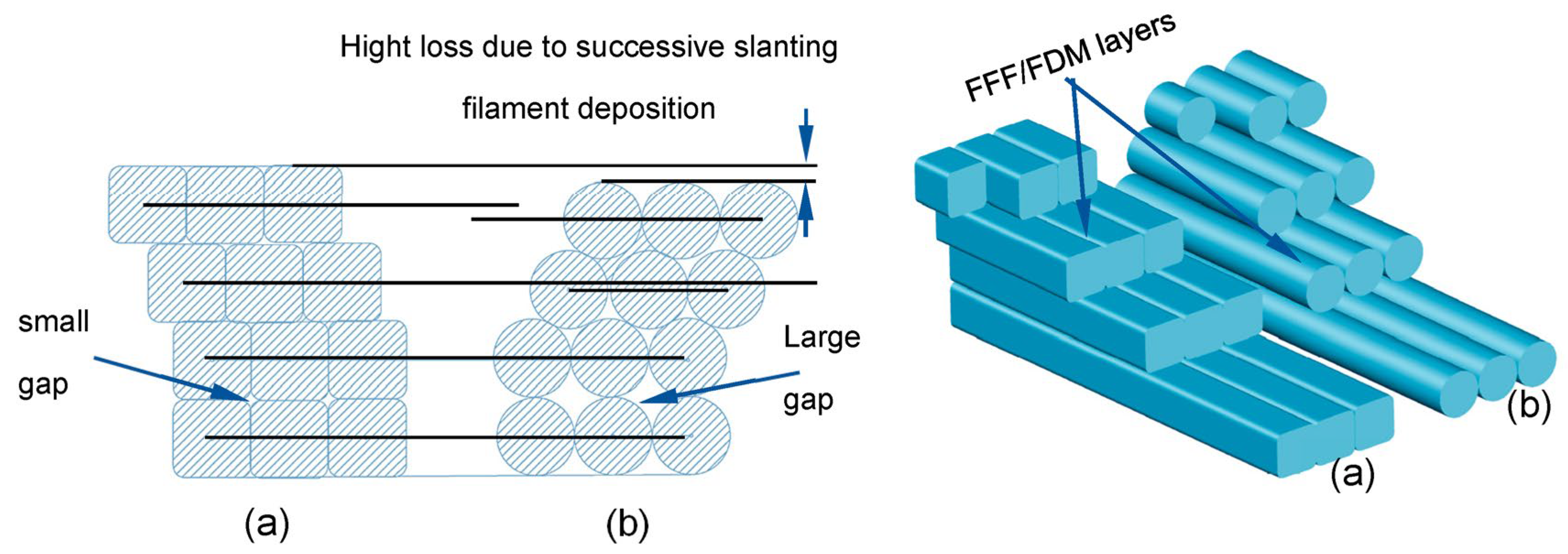
- The suggested filleted square shape extruder nozzle may deposit better build quality products than the commonly used circular extruder in FFF 3DP.
- ▪
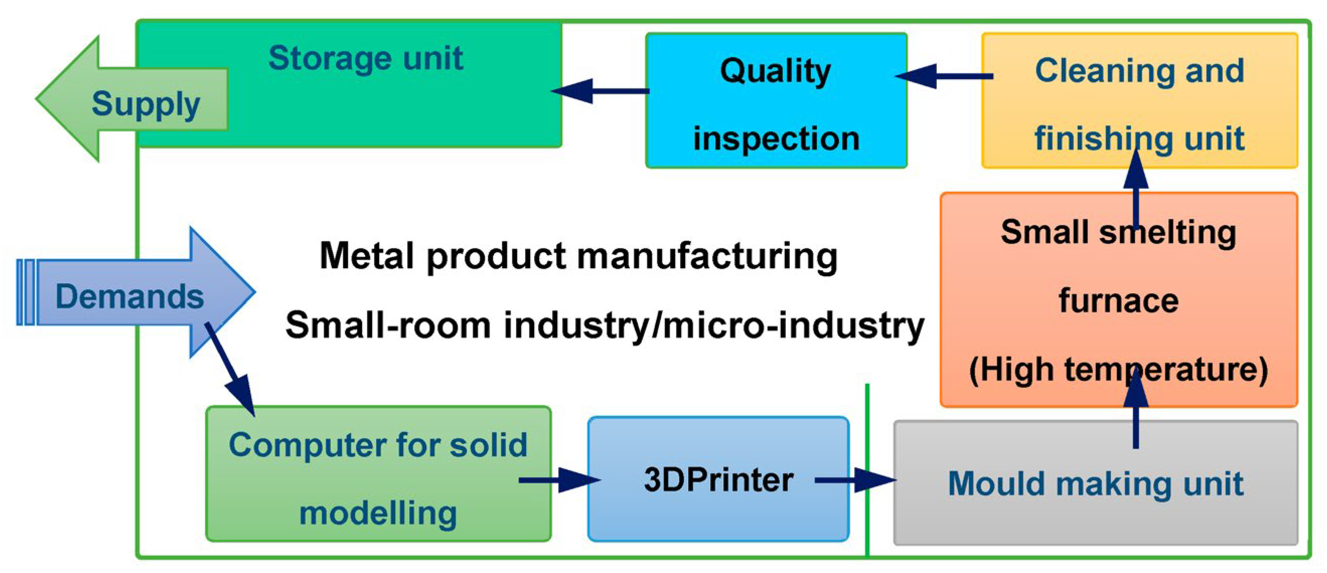
- Such low-cost process development could enable the establishment of a room-based or micro-scale RC/RIC industry with a low initial investment cost.
Funding
Data Availability Statement
Conflicts of Interest
Nomenclature
| 3DP | 3D Printing |
| AI | Artificial Intelligence |
| AM | Additive Manufacturing |
| DLP | Digital Light Processing |
| DLS | Digital Light Synthesis |
| DM | Direct Manufacturing |
| DMLS | Direct Metal Laser Sintering |
| DMP | Direct Metal Printing |
| EBM | Electron Beam Melting |
| FDM | Fused Deposition Modelling |
| FEP | Fluorinated Ethylene Propylene |
| FFF | Fused Filament Fabrication |
| IC | Investment Casting |
| LPBF | Laser Powder Bed Fusion |
| MJF | Multi Jet Fusion |
| MMC | Metal Matrix Composite |
| PLA | Polylactic Acid |
| RC | Rapid Casting |
| RP | Rapid Prototyping |
| SLA | Stereolithography |
| SLM | Selective Laser Melting |
| SLS | Selective Laser Sintering |
References
- Cheah, C.M.; Chua, C.K.; Lee, C.W.; Feng, C.; Totong, K. Rapid prototyping and tooling techniques: A review of applications for rapid investment casting. Int. J. Adv. Manuf. Technol. 2005, 25, 308–320. [Google Scholar] [CrossRef]
- Gibson, I.; Rosen, D.; Stucker, B. Additive Manufacturing Technologies: 3D Printing, Rapid Prototyping, and Direct Digital Manufacturing, 2nd ed.; Springer: Berlin/Heidelberg, Germany, 2015; ISBN 9781493921126. [Google Scholar]
- Vafadar, A.; Guzzomi, F.; Rassau, A.; Hayward, K. Advances in metal additive manufacturing: A review of common processes, industrial applications, and current challenges. Appl. Sci. 2021, 11, 1213. [Google Scholar] [CrossRef]
- Ngo, T.D.; Kashani, A.; Imbalzano, G.; Nguyen, K.T.Q.; Hui, D. Additive manufacturing (3D printing): A review of materials, methods, applications and challenges. Compos. Part B Eng. 2018, 143, 172–196. [Google Scholar] [CrossRef]
- Singh, J.; Singh, R.; Singh, H. Dimensional accuracy and surface finish of biomedical implant fabricated as rapid investment casting for small to medium quantity production. J. Manuf. Process. 2017, 25, 201–211. [Google Scholar] [CrossRef]
- Niemelä, M.; Shi, A.; Shirowzhan, S.; Sepasgozar, S.M.E.; Liu, C. 3D printing architectural freeform elements: Challenges and opportunities in manufacturing for industry 4.0. In Proceedings of the 2019 36th International Symposium on Automation and Robotics in Construction (ISARC 2019), Banff, AB, Canada, 21–24 May 2019; pp. 1298–1304. [Google Scholar] [CrossRef]
- Varotsis, A.B. 3D Printing Trends Q1 2019. Available online: https://www.hubs.com/blog/3d-printing-trends-q1-2019/ (accessed on 9 February 2023).
- Roberts, T.; Bartkova, B. Additive Manufacturing Trend Report 2021 (3D Printing Market Growth in the Year of the COVID-19). Available online: https://f.hubspotusercontent10.net/hubfs/4075618/Additive%20manufacturing%20trend%20report%202021.pdf?utm_campaign=Gated%20Content%20Downloads&utm_medium=email&_hsmi=82605589&_hsenc=p2ANqtz-9pM5X9Hu5jL_49jLKLdBARaGb5PVPhM3kYwzk2c36z2bmdpMZRLJiSd4n5ZKSZOJoCbPnSwFXfi64pLJvjvFjceDPf3w&utm_content=82605589&utm_source=hs_automation (accessed on 12 August 2023).
- 3D Printing Market Size. Available online: https://www.fortunebusinessinsights.com/industry-reports/3d-printing-market-101902 (accessed on 10 September 2023).
- Industrial 3D Printing Market Size, Share and Growth. Available online: https://www.alliedmarketresearch.com/industrial-3d-printing-market-A17129 (accessed on 10 September 2023).
- 3D Printing Market Size to Worth around USD 98.31 BN. Available online: https://www.globenewswire.com/en/news-release/2023/03/28/2635882/0/en/3D-Printing-Market-Size-to-Worth-Around-USD-98-31-BN-by-2032.html (accessed on 10 August 2023).
- MIT Comparing AM Processes. Available online: http://apt.mit.edu/am-process-comparisons (accessed on 1 February 2022).
- Alsoufi, M.S.; Elsayed, A.E. Surface Roughness Quality and Dimensional Accuracy—A Comprehensive Analysis of 100% Infill Printed Parts Fabricated by a Personal/Desktop Cost-Effective FDM 3D Printer. Mater. Sci. Appl. 2018, 9, 11–40. [Google Scholar] [CrossRef]
- Pandian, A.; Belavek, C. A review of recent trends and challenges in 3D printing. In Proceedings of the 2016 ASEE North Central Section Conference, Michigan, MI, USA, 18–19 March 2016; pp. 1–17. [Google Scholar]
- Yarbrough, J.; Shearer, A.B.; Bent, S.F. Next generation nanopatterning using small molecule inhibitors for area-selective atomic layer deposition. J. Vac. Sci. Technol. A 2021, 39, 021002. [Google Scholar] [CrossRef]
- How to get all-metal parts with 3D FDM printing. Available online: https://filament2print.com/gb/blog/70_sintering-metal-parts-fdm-3d-printing.html (accessed on 12 August 2023).
- Markforged Types of 3D Printing in Metal. Available online: https://markforged.com/resources/learn/design-for-additive-manufacturing-metals/metal-additive-manufacturing-introduction/types-of-3d-printing-metal (accessed on 18 September 2023).
- Wohlers Associates. Wohlers Report 2021. 2021. Available online: wohlersassociates.com (accessed on 10 September 2023).
- Stefaniak, A.B.; Bowers, L.N.; Knepp, A.K.; Luxton, T.P.; Peloquin, D.M.; Ham, J.E.; Wells, J.R.; Johnson, A.R.; Lebouf, R.F.; Martin, S.B.; et al. Particle and vapor emissions from vat polymerization desktop-scale 3-dimensional printers. J. Occup. Environ. Hyg. 2020, 16, 519–531. [Google Scholar] [CrossRef] [PubMed]
- Formlabs Introduction to Casting for 3D Printed Jewelry Patterns. Available online: https://formlabs.com/company/recommended-casting-houses (accessed on 10 August 2023).
- Yap, Y.L.; Yeong, W.Y. Additive manufacture of fashion and jewellery products: A mini review: This paper provides an insight into the future of 3D printing industries for fashion and jewellery products. Virtual Phys. Prototyp. 2014, 9, 195–201. [Google Scholar] [CrossRef]
- Ott, D.; Raub, C.J. Investment Casting of Gold Jewellery. Gold Bull. 1986, 19, 34–39. [Google Scholar] [CrossRef]
- Pattnaik, S.; Jha, P.K.; Karunakar, D.B. A review of rapid prototyping integrated investment casting processes. Proc. Inst. Mech. Eng. Part L J. Mater. Des. Appl. 2014, 228, 249–277. [Google Scholar] [CrossRef]
- A Modern Casting Staff Report. Census of World Casting Production: Total Casting Tons Dip in 2019; Modern Casting, 2021, 28. Available online: https://www.qgdigitalpublishing.com/publication/?m=55001&i=687958&p=30&ver=html5 (accessed on 12 August 2023).
- Pattnaik, S.; Karunakar, D.B.; Jha, P.K. Developments in investment casting process—A review. J. Mater. Process. Technol. 2012, 212, 2332–2348. [Google Scholar] [CrossRef]
- Stefanescu, D.M. ASM Handbook Volume 15:Casting; ASM International: Michigan, MI, USA, 1998; ISBN 978-0871700223. [Google Scholar]
- Olson, D. What Is Investment Casting and How Does It Work? Available online: https://www.metaltek.com/blog/what-is-investment-casting-and-how-does-it-work/ (accessed on 19 September 2023).
- The Accuracy of Investment Casting. Available online: https://www.improprecision.com/introduction-investment-casting-accuracy-grades/ (accessed on 10 September 2023).
- Xu, M.; Lekakh, S.N.; Von Richards, L. Thermal property database for investment casting shells. Int. J. Met. 2016, 10, 342–347. [Google Scholar] [CrossRef]
- Chen, Y.; Zhao, E.; Kong, F.; Xiao, S. Fabrication of thin-walled high-temperature titanium alloy component by investment casting. Mater. Manuf. Process. 2013, 28, 605–609. [Google Scholar] [CrossRef]
- Klotz, U.E.; Legner, C.; Bulling, F.; Freitag, L.; Faßauer, C.; Schafföner, S.; Aneziris, C.G. Investment casting of titanium alloys with calcium zirconate moulds and crucibles. Int. J. Adv. Manuf. Technol. 2019, 103, 343–353. [Google Scholar] [CrossRef]
- Li, F.; Ji, X.; Wu, Z.; Qi, C.; Lai, J.; Xian, Q.; Sun, B. Digital light processing 3D printing of ceramic shell for precision casting. Mater. Lett. 2020, 276, 2–5. [Google Scholar] [CrossRef]
- Mukhtarkhanov, M.; Perveen, A.; Talamona, D. Application of stereolithography based 3D printing technology in investment casting. Micromachines 2020, 11, 946. [Google Scholar] [CrossRef]
- Tiwary, V.K.; Arunkumar, P.; Deshpande, A.S.; Rangaswamy, N. Surface enhancement of FDM patterns to be used in rapid investment casting for making medical implants. Rapid Prototyp. J. 2019, 25, 904–914. [Google Scholar] [CrossRef]
- Wang, D.; Dong, A.; Zhu, G.; Shu, D.; Sun, J.; Li, F.; Sun, B. Rapid casting of complex impeller based on 3D printing wax pattern and simulation optimization. Int. J. Adv. Manuf. Technol. 2018, 100, 2629–2635. [Google Scholar] [CrossRef]
- Macků, M.; Horáček, M. Applying RP-FDM Technology to Produce Prototype Castings Using the Investment Casting Method. Arch. Foundry Eng. 2012, 12, 75–82. [Google Scholar] [CrossRef]
- Wang, S.; Miranda, A.G.; Shih, C. A study of investment casting with plastic patterns. Mater. Manuf. Process. 2010, 25, 1482–1488. [Google Scholar] [CrossRef]
- Vaezi, M.; Safaeian, D.; Shakeri, M. Integration of reverse engineering and rapid technologies for rapid investment casting of gas turbine blades. Virtual Phys. Prototyp. 2011, 6, 225–239. [Google Scholar] [CrossRef]
- Bassoli, E.; Gatto, A.; Iuliano, L.; Violante, M.G. 3D printing technique applied to rapid casting. Rapid Prototyp. J. 2007, 13, 148–155. [Google Scholar] [CrossRef]
- Vallejos Baier, R.; Contreras Raggio, J.I.; Toro Arancibia, C.; Bustamante, M.; Pérez, L.; Burda, I.; Aiyangar, A.; Vivanco, J.F. Structure-function assessment of 3D-printed porous scaffolds by a low-cost/open source fused filament fabrication printer. Mater. Sci. Eng. C 2021, 123, 111945. [Google Scholar] [CrossRef]
- Mushtaq, R.T.; Iqbal, A.; Wang, Y.; Khan, A.M.; Petra, M.I. Advancing PLA 3D Printing with Laser Polishing: Improving Mechanical Strength, Sustainability, and Surface Quality. Crystals 2023, 13, 626. [Google Scholar] [CrossRef]
- Minetola, P.; Calignano, F.; Galati, M. Comparing geometric tolerance capabilities of additive manufacturing systems for polymers. Addit. Manuf. 2020, 32, 101103. [Google Scholar] [CrossRef]
- Minetola, P.; Galati, M. A challenge for enhancing the dimensional accuracy of a low-cost 3D printer by means of self-replicated parts. Addit. Manuf. 2018, 22, 256–264. [Google Scholar] [CrossRef]


| Characteristics | Metallic Product Manufacturing Through: | |
|---|---|---|
| FDM/FFF or SLA Patterns | Direct 3DP | |
| Advantages: |
|
|
| Limitations: |
|
|
| Research scope: |
| |
| Characteristics | FDM/FFF process | DLP 3DP |
|---|---|---|
| Cost: |
|
|
| Consumable: |
|
|
| Running skills: |
|
|
| Health issue: |
|
|
| Maintenance: |
|
|
| Running cost: |
|
|
| Accuracy: |
|
|
| Surface quality: |
|
|
| Complexity: |
|
|
| Material savings: |
|
|
| Characteristics | Low-Cost (FFF, SLA) 3DP (AM) Technologies | Investment Casting | Rapid Investment Casting/Rapid Casting |
|---|---|---|---|
| Cost: | Low | Metallic die price is affordable in mass production only. | Profitable for job production to batch production, reverse engineering, just-in-time, and cellular manufacturing |
| Material: | Low melting points like PLA, PVA, WAX, etc. | Metals, alloys, super alloys | Metals, alloys, super alloys |
| Production time: | 1 to 7 days for a batch of product | Significant time consumed initially for making metallic dies | 2-8 days for a batch of product |
| Geometry complexity: | FDM/FFF can make any complex internal geometry, and any externally connected internal geometry can be made using SLA 3DP | Any externally connected internal geometry can be made using SLA 3DP | Any externally linked internal geometry can be made using SLA 3DP |
| Just-in-time: | Possible | Not viable for small amounts and quick delivery | Possible |
| Cellular manufacturing: | Possible | NA | Possible |
| Reverse engineering: | Possible | NA | Possible |
| Researcher/s Details | Research Objectives | Materials | Results/Conclusion |
|---|---|---|---|
| (2021), F. Li et al. [32] |
|
|
|
| (2020), M. Mukhtarkhanov et al. [33] |
|
|
|
| (2019), UE Klotz et al. [31] |
|
|
|
| (2019), V. K. Tiwary et al. [34] |
|
|
|
| (2018), D. Wang et al. [35] |
|
|
|
| (2013), Y. Chen et al. [30] |
|
|
|
| (2012), M. Macků and M. Horáček [36] |
|
|
|
| (2010), S. Wang et al. [37] |
|
|
|
| (2011), M. Vaezi et al., 2011 [38] |
|
|
|
| (2007), E. Bassoli and A. Gatto [39] |
|
|
|
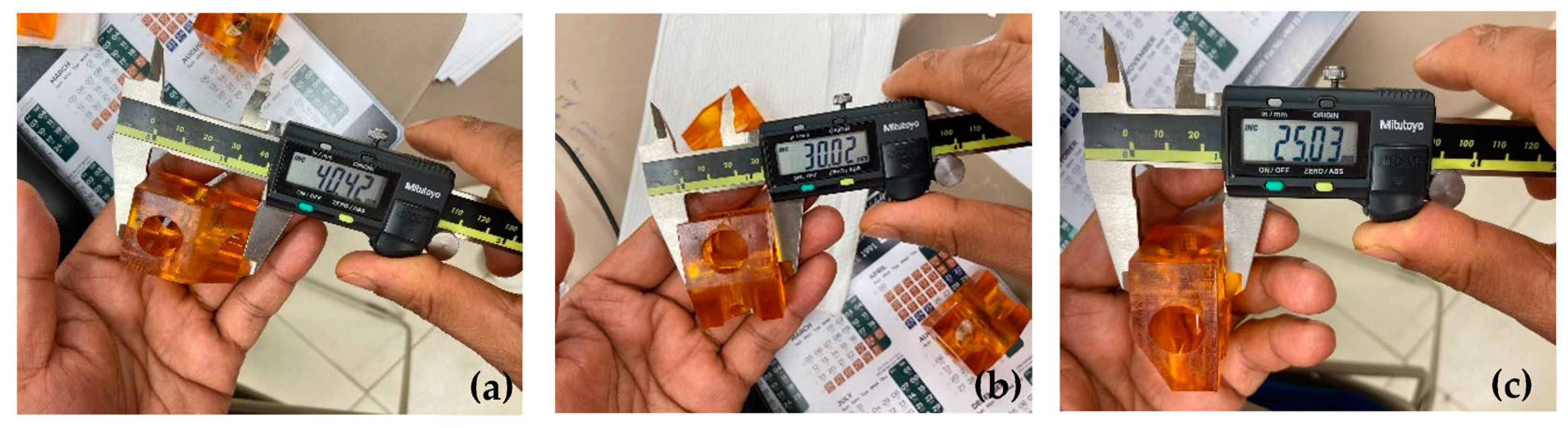
| 3D Object Directions | 1st Model Dimension (Actual Target) | 1st Printed Object Dimensions (mm) | Tuned 2nd Model Dimensions (mm) | 3DP Specimen after Solid Model Tuning (mm) | Actual Error (%) (Before Validation) | Error (%) in 3D-Printed Specimen after Validation | Reduction in Error (%) after First Validation |
|---|---|---|---|---|---|---|---|
| X | 40 | 40.48 | 39.52 | 40.42 | 1.2% | 1.05% | 0.15% |
| Y | 30 | 30.12 | 29.88 | 30.02 | 0.4% | 0.07% | 0.33% |
| Z | 25 | 24.51 | 25.51 | 25.03 | −2.04% | 0.12% | 2.16% |
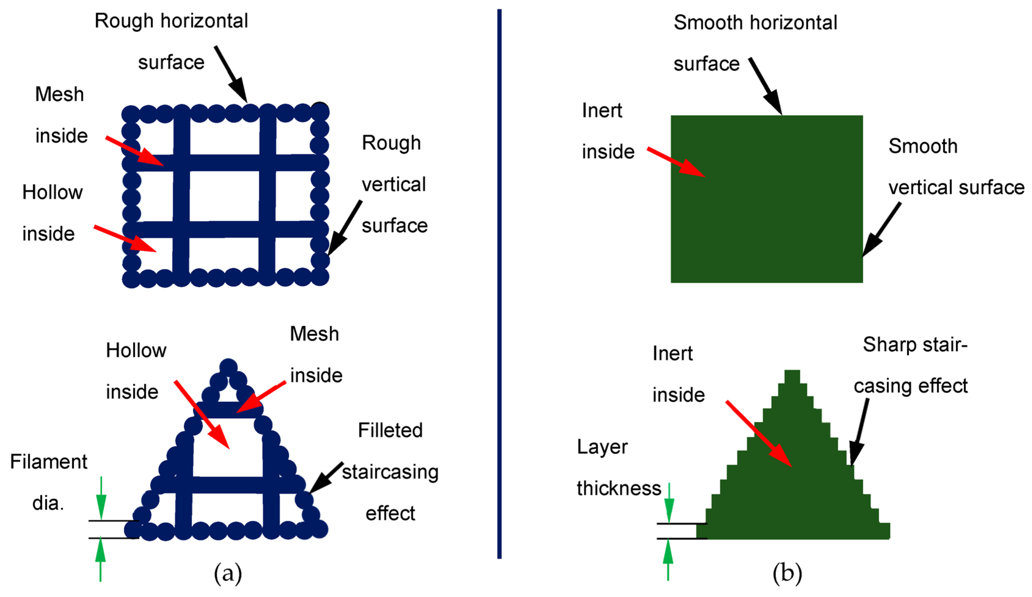
| Pattern-Making Process and Material | Observations | |||
|---|---|---|---|---|
| Pattern Surface Quality | Pattern Burning Effects | Mould Quality | Rapid Casting Status | |
| FFF/PLA: |
|
|
|
|
| SLA(DLP)/ Wax: |
|
|
|
|
Disclaimer/Publisher’s Note: The statements, opinions and data contained in all publications are solely those of the individual author(s) and contributor(s) and not of MDPI and/or the editor(s). MDPI and/or the editor(s) disclaim responsibility for any injury to people or property resulting from any ideas, methods, instructions or products referred to in the content. |
© 2023 by the author. Licensee MDPI, Basel, Switzerland. This article is an open access article distributed under the terms and conditions of the Creative Commons Attribution (CC BY) license (https://creativecommons.org/licenses/by/4.0/).
Share and Cite
Haldar, B. Enhancing Dimensional Accuracy in Budget-Friendly 3D Printing through Solid Model Geometry Tuning and Its Use in Rapid Casting. Machines 2023, 11, 1020. https://doi.org/10.3390/machines11111020
Haldar B. Enhancing Dimensional Accuracy in Budget-Friendly 3D Printing through Solid Model Geometry Tuning and Its Use in Rapid Casting. Machines. 2023; 11(11):1020. https://doi.org/10.3390/machines11111020
Chicago/Turabian StyleHaldar, Barun. 2023. "Enhancing Dimensional Accuracy in Budget-Friendly 3D Printing through Solid Model Geometry Tuning and Its Use in Rapid Casting" Machines 11, no. 11: 1020. https://doi.org/10.3390/machines11111020
APA StyleHaldar, B. (2023). Enhancing Dimensional Accuracy in Budget-Friendly 3D Printing through Solid Model Geometry Tuning and Its Use in Rapid Casting. Machines, 11(11), 1020. https://doi.org/10.3390/machines11111020