Abstract
In recent years, the recreational and commercial use of flight and driving simulators has become more popular. All these applications require the calculation of orientation in either two or three dimensions. Besides the Euler angles notation, other alternatives to represent rigid body rotations include axis-angle notation, homogeneous transformation matrices, and quaternions. All these methods involve transcendental functions in their calculations, which represents a disadvantage when these algorithms are implemented in hardware. The use of transcendental functions in software-based algorithms may not represent a significant disadvantage, but in hardware-based algorithms, the potential of rational models stands out. Generally, to calculate transcendental functions in hardware, it is necessary to utilize algorithms based on the CORDIC algorithm, which requires a significant amount of hardware resources (parallel) or the design of a more complex control unit (pipelined). This research presents a new procedure for model orientation using rational trigonometry and quaternion notation, avoiding trigonometric functions for calculations. We describe the orientation of a gimbal mechanism presented in many applications, from autonomous vehicles such as cars or drones to industrial manipulators. This research aims to compare the efficiency of a rational implementation to classical modeling using the techniques mentioned above. Furthermore, we simulate the models with software tools and propose a hardware architecture to implement our algorithms.
1. Introduction
The kinematic analysis of a rigid body is usually done by taking its center of mass as a reference. However, since not all bodies have high symmetry, it is necessary to specify both position and orientation. The orientation can be visualized by adding an orthogonal vector base to the center of mass. Many methods describe the orientation of a rigid body; however, two of the most common techniques are the Euler angles and the quaternions.
Euler angles are properly called the six configurations in which the initial and final rotations are made on the same axis (e.g., z-y-z). On the other hand, Tait–Bryan angles (a.k.a., nautical angles) are three angles that define a rotation uniquely concerning the body reference frame. Unlike Euler angles, the Tait–Bryan procedure develops sequence rotation about different axes. In some literature, the Tait–Bryan sequence, x-y-z, is called roll, pitch, and yaw. This rotation sequence is widely used in aerospace engineering, but in some references, Tait–Bryan and Euler angles are used under the same terminology and are simply called Euler angles.
The most important quality of Euler orientation is that any combination of rotations is equivalent to a single rotation. Although matrix notation was introduced after the Euler results, it can be shown that the rotation’s composition turns mathematically equivalent to the product of orthogonal matrices. Another way of representing rotations is known as the Euler vector or rotation vector, which states that every rotation matrix has a real Eigenvector and represents the axis of rotation. Based on this idea, Euler introduced an alternative notation to determine the orientation, defined as a vector perpendicular to the plane of rotation the module of which is equivalent to the rotated angle. Therefore, any vector through the origin can represent a rotation.
A similar concept to Euler vectors is the quaternion representation, which includes vectors of four components and a module equal to one. This has many advantages over Euler representations since it is numerically more stable, computationally more efficient and easier to convert into matrices.
The orientation of a rigid body in 3D space changes by rotation, and when the solid has rotational symmetry, not all rotations are visually distinguishable. For instance, this happens when a sphere is rotated around its center in any direction or a cylinder around its symmetry-axis. All the above methods can be studied as purely geometric concepts, applicable to describing rigid bodies’ orientation in space.
Regardless of the chosen method, there are two ways to implement an algorithm in order to compute the orientation of a rigid body: by software or by hardware. These involve transcendental functions, from their definitions to their calculations. On the other hand, avoiding transcendental functions in software-based algorithms may not represent a great advantage, because current processors are so fast. However, in hardware-based algorithms, the potential of rational models stands out.
Generally, to compute transcendental functions in hardware, it is common to use algorithms based on CORDIC, which requires a large number of hardware resources (parallel) or the design of a complex control unit (pipelined). Some CORDIC algorithm implementations require 21 stages to compute a transcendental function, and it is possible to reduce these stages to at least 11 by losing accuracy. Many researchers use the CORDIC algorithm to compute orientation [1,2], and some of them combine this with quaternion representations to compute orientation [3]. In robotics, it is mandatory that applications compute variables at least 30 times per second, or even faster [4].
This research presents a novel approach to model orientation using rational trigonometry, avoiding trigonometric functions. We describe the orientation of a gimbal mechanism present in many applications, from autonomous vehicles such as cars or drones to industrial manipulators. This work aims to compare how the efficiency of implementation in a rational way to classical modeling that utilizes the techniques previously mentioned.
The main contributions of this paper are two novel models based on rational trigonometry: one for the orientation of a gimbal mechanism and the other for the position and orientation of a wrist mechanism, based on quaternions and dual quaternions in a rational way, respectively. It is worth mentioning that none of these proposed models involve using transcendental functions, which reduces the hardware demands of rational models for synthesizing circuits that compute additions, subtractions, multiplications, and some divisions. This proposition has the advantage of allowing more efficient and smaller hardware implementations than the classic CORDIC-based implementations.
The rest of the work is arranged as follows. In Section 2, a review of related works is presented. Section 3 and Section 4 are oriented to illustrate our proposed approach related to the quaternion transformation. Section 5 presents an application focused on orienting a robotic arm employing rational modeling. Section 6 shows the results of implementing our proposal in rational Euler angles and on physical hardware. Lastly, Section 7 is focused on concluding and highlighting some advantages of our proposal. Furthermore, Appendix A explains rational concepts equivalent to distance and angle, for the better understanding of the reader.
2. Related Work
In the film and advertising industry, there has been a need to use robotics to improve and automate the film and commercial recording process. One of the most used mechanisms to define the orientation of cameras and other devices is the so-called gimbal. This mechanism is widely used in patents [5,6,7,8] and even in measuring large-scale systems such as buildings [9].
In the robotics field, companies such as the Motorized Precision Company use industrial robotic arms to perform video capture. This company has adapted different kinematic modeling and trajectory generation techniques to achieve a wide range of features on its products, and orientation modeling is one of the fundamental factors in achieving all these features.
Another field in which research has been invested to improve orientation models is drone design [10,11]. Companies such as DJI sell devices that offer a wide range of features, including autonomous flight and flight stabilization in different environmental conditions.
The orientation issue is present in many robotic mechanisms, from platform systems for virtual reality to the most sophisticated manipulative robots. The described orientation is influenced by the ease with which the user interprets it. For instance, Euler angles are often preferred for orientation models because they are easier to understand and interpret for the user [12].
Fu et al. [13] presented an efficient method based on dual quaternion for coordinate calibration of dual robots in collaborative motion. In contrast, we have developed a modeling technique to describe the orientation of a gimbal mechanism using quaternions in a rational way. We have called this method rational modeling because no trigonometric functions have been used, as is common in all algorithms included in the bibliography [14,15,16]. We generate a rational model analog for Euler angles. Then, we develop a new model to describe the orientation of a robotic mechanism known as the spherical wrist, which is present in most industrial manipulators [17,18].
When we refer to robotic arms, the wrist mechanism is the one responsible for the orientation of the end effector. There are several techniques that try to reduce the number of operations needed to calculate the orientation, as developed in the following works [19,20,21].
In robotics and automation, orientation holds an important role in welding tasks because an efficient description of the orientation is required [22]. There are algorithms used to calculate the orientation either online or offline. However, most of the time, it is preferred to perform computations offline, since doing them online can be more cumbersome, and many times the accuracy requirements of the process are not met [23,24].
Nowadays, computer vision is present in many industrial processes. In this area, orientation modeling is required to control the position and orientation of objects in the workspace. For instance, some techniques have been developed to control the position and orientation of mobile robots based on control with neural networks [25,26].
3. Quaternions in a Rational Way
Rational trigonometry relies on the idea that algebra is more basic than analysis [27], and that the true measurements in elementary geometry should be quadratic rather than linear. In contrast to classical trigonometry, rational trigonometry does not require using transcendental functions [28]. We have included some rational concepts equivalent to distance and angle in Appendix A.
Quaternions are a form of four-dimensional algebra that lets us represent rotations in a simple way [29]. Every quaternion can be visualized in the diagram of Figure 1a, where the blue sphere is the sphere formed by all unit quaternions (i.e., ), and the green box is the usual vector space. Any quaternion q has a component on the t-axis and a projection in the vector space. Such a projection has a unique vector representing the rotation axis in the vector space.
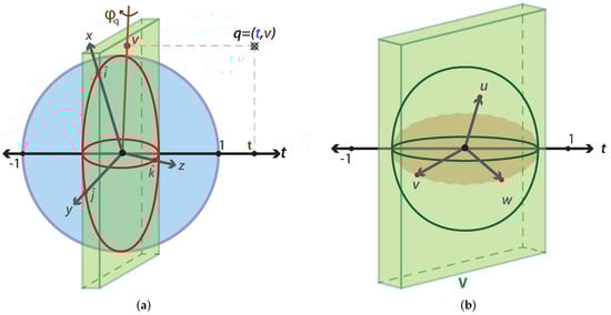
Figure 1.
Representation of four-dimensional space. (a) 4D space where the blue sphere represents an S3 sphere, the red sphere describes an S2 sphere, and q is a quaternion on the 4D space. (b) 4D space where the V space in green is equal to a 3D space and the t-axis is orthogonal to this space.
In order to understand the quaternion transformation, we analyze what happens with the space when we multiply by a general unit vector u. Suppose that vector u is orthogonal to the plane formed by v and w according to Figure 1b. The first step in analyzing the transformation is to break the 4D space into two planes, one span by and the second span by , as shown in Figure 2.
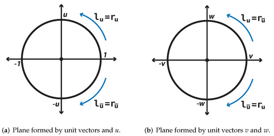
Figure 2.
Decomposition of 4D space.
Quaternion multiplication is not commutative, and it follows the rules:
On the plane generated by the multiplication between and u, the left and right generate a counter-clockwise rotation, as shown in Figure 2a. However, if we conjugate the imaginary unit u (i.e., ), the multiplication generates a clockwise rotation. In the plane spanned by , the multiplication by u on the left of any vector is equivalent to a counter-clockwise rotation. In contrast, the multiplication by u on the right is equivalent to a clockwise rotation. When we multiply by the conjugate of u, the right and left multiplication generates a counter-clockwise and clockwise rotation, respectively.
To develop a transformation in a classical way, we choose a quaternion as:
where is the amplitude of the rotation angle and , , are the components of the unit vector , which represents the rotation axis. The plane generated by is invariant under this transformation; however, the plane generated by suffers a rotation twice the magnitude of .
In the rational method, we choose a quaternion more easily, and therefore we choose a rotation axis and a half-turn to compute the t parameter:
where vector does not have to be unitary. The quaternion components are:
Lastly, the expression that describes a rotation in a rational way is the following:
where is the quadrance of q and when q is unitary. The connection between angles and half-turns is done by the relation between the classical parameterization and the rational parameterization of the unit circle:
4. Dual Quaternions in a Rational Way
Dual quaternions let us encode both position and orientation with only one quaternion [30]. A dual quaternion is a dual number where ; is tied to the dual part and satisfies the expression . Dual quaternion transformation can be analyzed into two parts, one for pure translation and one for pure rotation.
The pure translation is represented by a dual quaternion in the next form:
where , , and represent the displacements for each coordinate given in quadrances. Applying transformation (4) with and to the vector position in dual form , we obtain a new dual quaternion :
To represent a pure rotation transformation, we need to apply transformation (4), where quaternions and have the following form:
if and are unity, , but in another case, the transformation is:
the components of dual part , , , and are computed as:
where vectors and are the original position vector and the rotation axis, respectively. encodes the amplitude of rotation according to Equation (1).
5. Orientation Model
The robotic mechanism called the spherical wrist is responsible for guiding the tool placed at the robot’s tip. Figure 3 shows the wrist configuration of most industrial robotic arms.
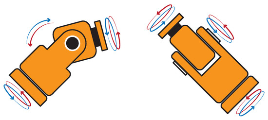
Figure 3.
Spherical wrist mechanism for orientation of a robot manipulator.
In order to orient the mechanism in an arbitrary form, it is mandatory to define at least three parameters (one for each joint). A common way to describe the orientation is as a sequence of rotations on the Cartesian axes x, y, and z.
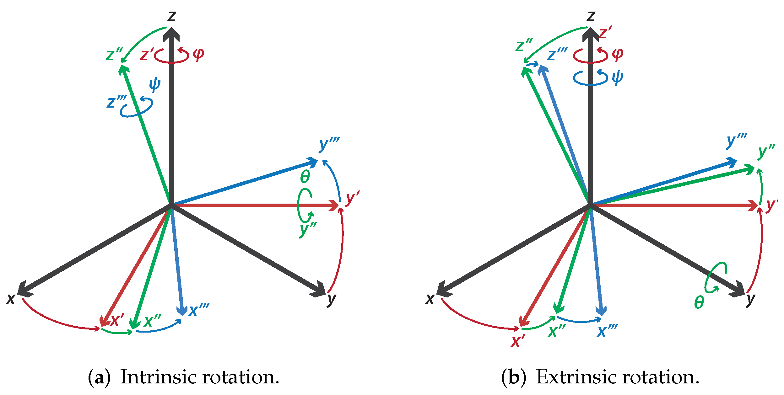
We use the z-y-z configuration for Euler angle notation, since it is used in most industrial robot manipulators. The letters z-y-z are the sequence of axes on which the rotations are made. Nevertheless, there are two ways to do this procedure, known as extrinsic and intrinsic rotations [31]. An extrinsic rotation applies rotations around the axes z-y-z belonging to the body frame, as shown in Figure 4a. On the other hand, an intrinsic rotation involves rotations around the axes z-y-z belonging to the general reference frame, as displayed in Figure 4b.
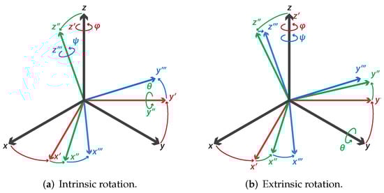
Figure 4.
Kinds of rotations.
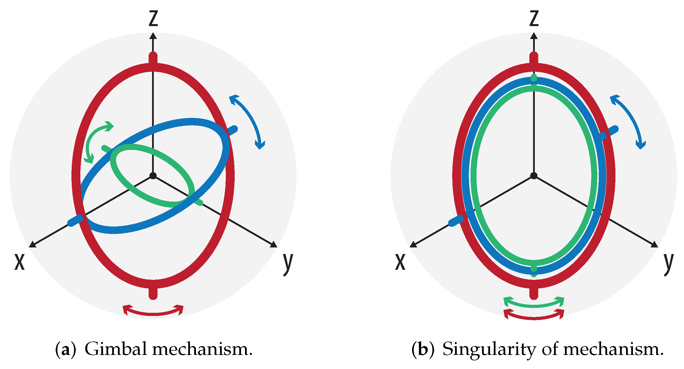
Euler angle representation is very useful because it adapts perfectly to the gimbal mechanism, as shown in Figure 5a, and can be adapted to the mechanism presented in Figure 3. However, the main problem of this mechanism is that it has singularities; i.e., when two different rotation axes are aligned, the mechanism loses a degree of freedom, as displayed in Figure 5b; the green axis rotates in the same direction as the red axis. In short, this implies that there are infinite solutions that put the mechanism in a particular configuration. Another popular representation for orientation is “roll-pitch-yaw”, also called Tait–Bryan angles, which is used in drones.
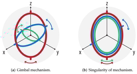
Figure 5.
Kinds of rotations.
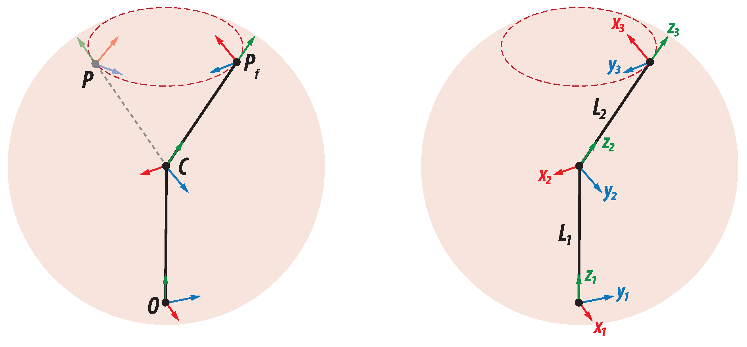
In contrast with the gimbal mechanism (Euler angles), the spherical wrist mechanism does not have its joints at the same point. Therefore, we should add some displacements between the joints, representing the length of robot joints. The following analysis is purely geometric. Figure 6 shows the breakdown movement according to the robotic orientation mechanism presented above.

Figure 6.
Orientation change.
According to Figure 6, it is important to point out the following:
- The point O corresponds to the fourth joint of an industrial robotic arm and is the first degree of freedom for the orientation mechanism. Its rotation axis is parallel to the axis of our main reference frame;
- The point C corresponds to the fifth joint of an industrial robotic arm and is the second degree of freedom for the orientation mechanism. This point is where the three rotation axes of the wrist intersect. The opening of this joint defines the final position of the wrist mechanism, but this point remains fixed under any variation of the three joint parameters;
- The point P corresponds to the sixth joint of the manipulator and is the last degree of freedom for the orientation mechanism. P is where the end effector is, as long as the first joint of the orientation mechanism does not change. Otherwise, the end effector moves through the circular trajectory to .
In this orientation modeling, we consider the reference frame at the point O that exactly matches the origin of the Cartesian space.
5.1. Euler Angles in a Rational Way
Euler angles can be represented in matrix form in the following way:
where , , and represent the amplitude of rotation. Each rotation matrix can be interchanged with a quaternion in the form of Equation (1), as shown below:
If we replace the angles by half-turns in the above expression, we obtain a rational representation for the configuration z-y-z of the Euler angles, as shown below:
where , , and are the magnitude of rotation according to Equation (2). Finally, by computing and simplifying, we obtain a rational model for Euler angles.
5.2. Real Mechanism in a Rational Way
In order to obtain a real model of the mechanism depicted in Figure 6 that gathers both position and orientation, we will use a dual quaternion for each joint as follows:
Applying Equation (17) for each joint, we obtain the following expression:
where each dual quaternion has the following parameters, according to Figure 6:
where .
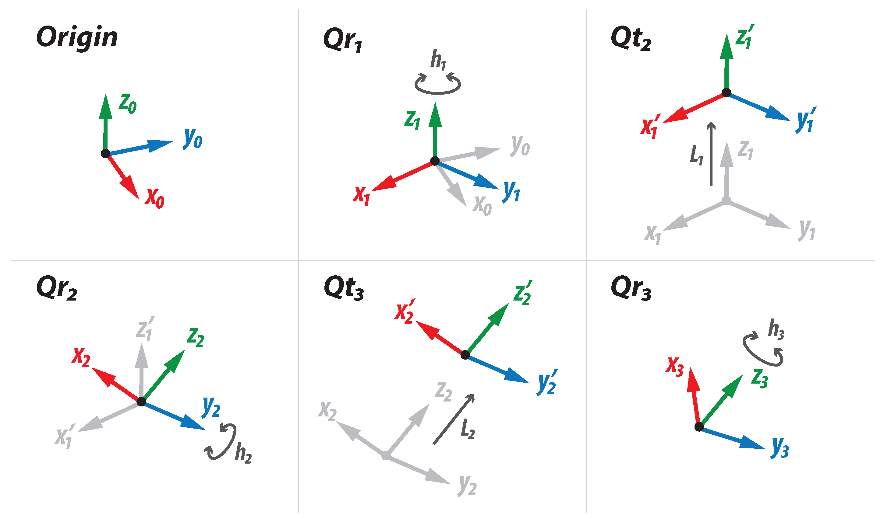
Computing all multiplications according to Equation (17), we obtain a unique dual quaternion whose components transform the original vector V into . Figure 7 shows each transformation independently, beginning from the origin frame and ending in the final frame of the wrist mechanism. Note that does not appear, since the first joint is on the origin of the reference frame.
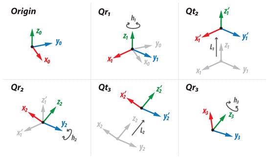
Figure 7.
Development of transformations for the rational orientation model.
6. Experimental Results
6.1. Rational Euler Angles Implementation
The direct kinematic problem for orientation consists of finding the final orientation given three joint parameters. These three parameters are generally given in degrees or radians. However, they could also be provided in any of the aperture measurements discussed in Appendix A (spread, turn, or half-turn).
A common way of solving the direct kinematics for the orientation of a robotic arm is to employ rotation matrices to represent the Euler angles z-y-z. As already mentioned, this representation is not the most convenient, but it is one of the easiest to understand. The equations are obtained after multiplying the three rotation matrices corresponding to the axes z-y-z successively by an arbitrary vector :
Thus far, the rotation has not been described and the equations do not contain transcendental functions. Considering the concept of half-turn proposed in the Appendix A, Equations (24)–(26) can be transformed in such a way that all the trigonometric functions disappear, as shown below:
Equations (27)–(29) could be considered as the description of the orientation with Euler angles, but in a rational way, since they do not contain any transcendental functions. The parameters involved in the calculation of the orientation are and , where is a parameter obtained with Equation (2).
Vector corresponds to the axis of rotation on which each half-turn acts. The values , , and represent the coordinates of the resulting vector oriented according to the three parameters of half-turns entered by the user. As a result, Equations (21)–(23) represent an alternative to model the orientation without the need to involve trigonometric functions.
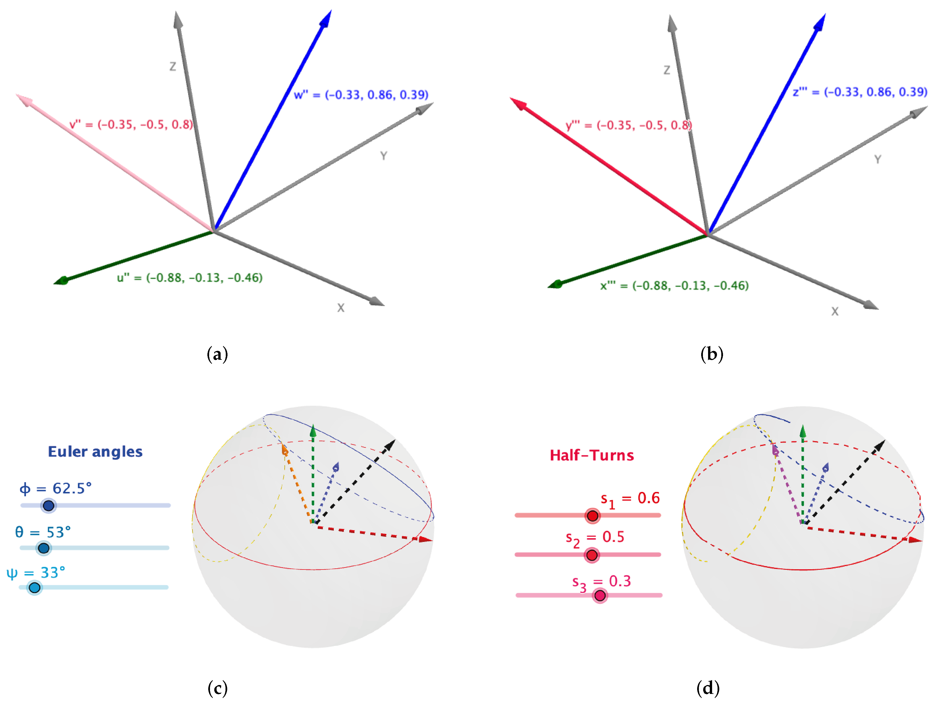
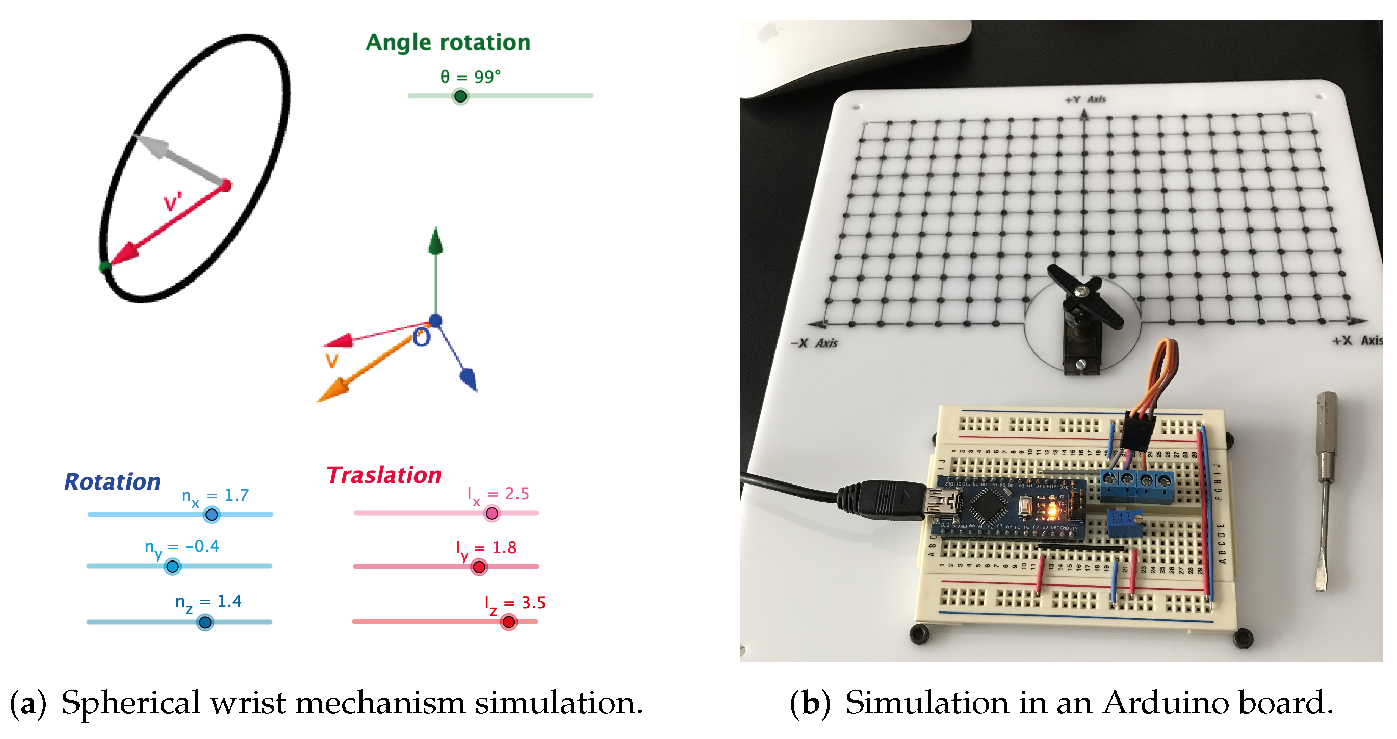
For Euler angle implementation, we used a graphical software called GeoGebra. Figure 8a,b show the implementation of intrinsic and extrinsic rotation, respectively. On other hand, Figure 8c exhibits the classical implementation of Euler angles using Equations (24)–(26). Finally, Figure 8d displays the rational replacement for Euler angles using Equations (27)–(29). The simulation of the wrist mechanism with dual quaternions is presented in Figure 9a. Additionally, the rotation algorithms for one axis were implemented in an Arduino-nano board, in order to prove how they work in real life after compiling them in the Arduino IDE software, as pictured in Figure 9b.
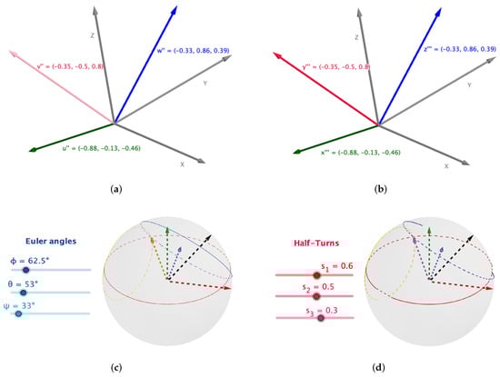
Figure 8.
Simulation of different rotation techniques. (a) Intrinsic rotation, where rotations were performed around the body reference frame with parameters ϕ = 111°, ɵ = 67°, and φ = 60°. (b) Extrinsic rotation, where rotations were performed around the general reference frame with parameters ϕ = 60°, ɵ = 67°, and φ = 111°. (c) Classical rotation algorithm with three parameters given in angles. (d) Rational rotation algorithm with three parameters given in rational form (half-turns).
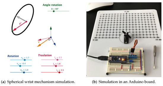
Figure 9.
Simulation for the spherical wrist mechanism.
6.2. Hardware Implementation
As mentioned in the above section, software simulation was done using GeoGebra. Hardware implementation was done with an Intel FPGA using the rational analog for Euler angles (half-turn).
For hardware implementation, we used a 16-bit fixed-point architecture, where the integer part has eight bits (one bit for the sign and seven bits for the half-turn) and the other eight bits are for the fractional part of the half-turn. Table 1 shows the relation between the number of bits of the integer part and the maximum angle rotation in degrees that can be represented. Notice that we are describing the amount of rotation in “half-turn”, but in Table 1, this amount is expressed in degrees for didactic reasons.

Table 1.
Relation between bits for the integer part and half-turns in degrees.
The first column begins with two bits because the integer part always has one bit for the sign. Table 2 shows the relation between the number of bits of the fractional part and the minimum angle rotation in degrees that can be represented.
Table 2.
Relation between bits for the fractional part and half-turns in degrees.
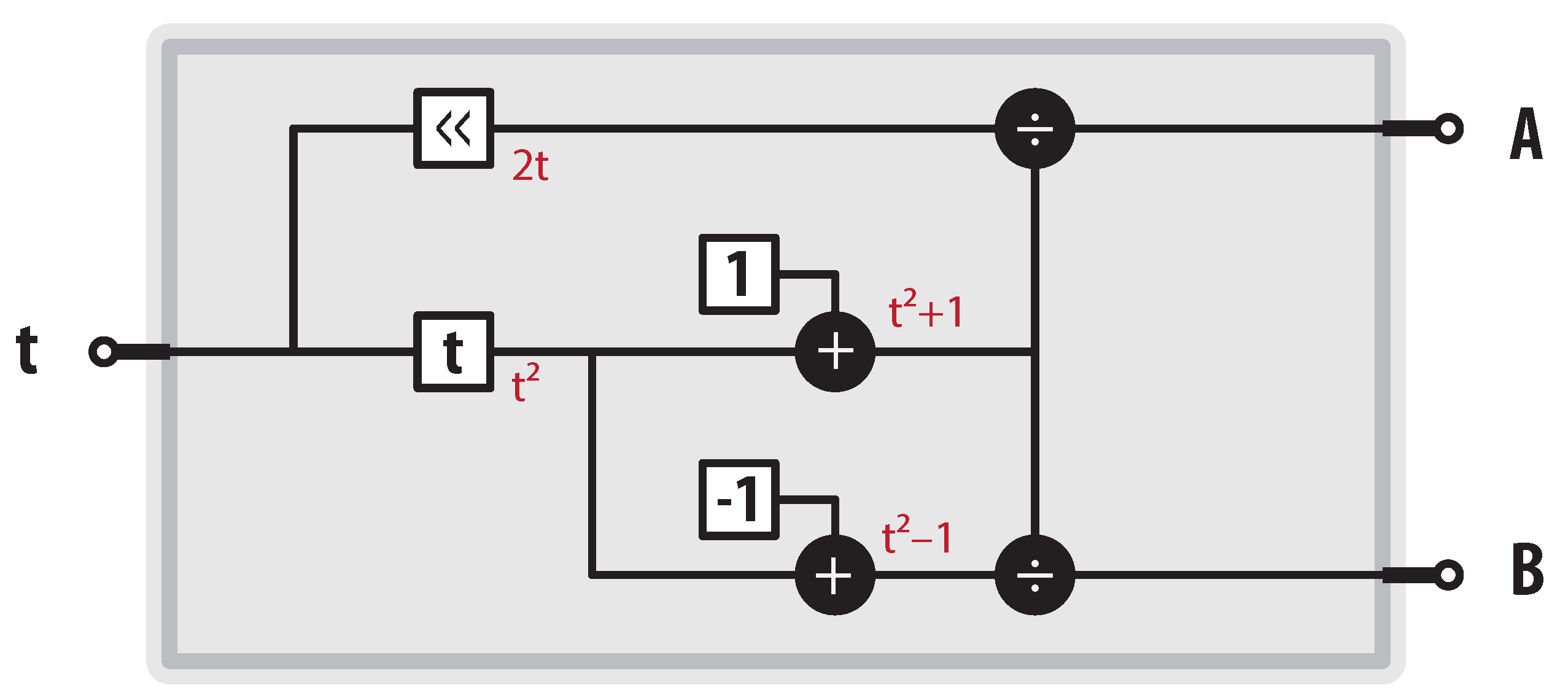
The first step for computing the final orientation of the gimbal mechanism is to find the rotation generated through a single axis. However, to easily calculate the final orientation of each rotation, we must compute the coefficients involved in each. Figure 10 depicts how to compute the rational replacements for the transcendental functions sine and cosine according to Equation (5). Notice that output A is the rational analog for the sine function and output B is the rational analog for the cosine function.
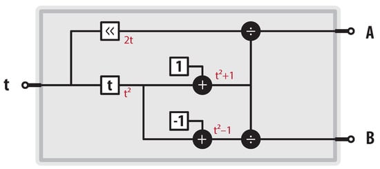
Figure 10.
FACTOR module for computing coefficients.
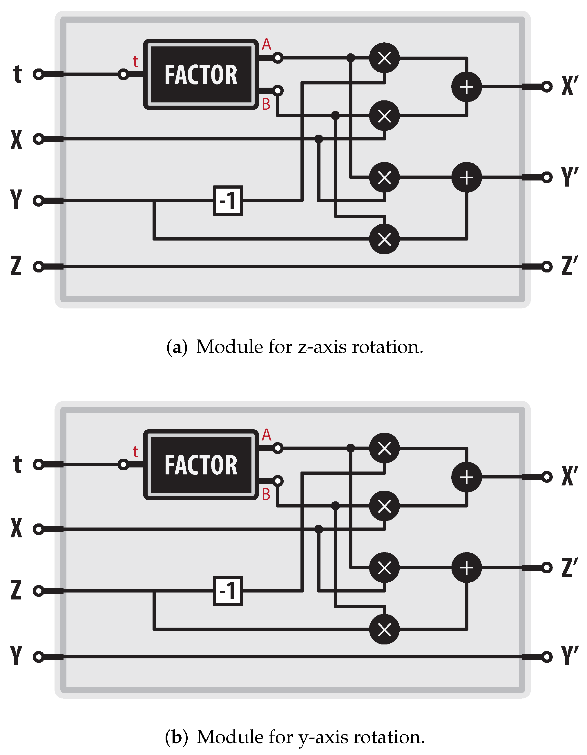
Because the gimbal mechanism uses the Euler angles in the z-y-z sequence, we can compute the final orientation using the modules presented in Figure 11. The module displayed in Figure 11a computes the rotation on the z- and the module shown in Figure 11b computes the rotation on the y-. Notice that the module named “FACTOR” is the module depicted in Figure 10.
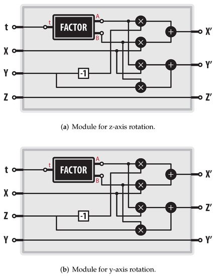
Figure 11.
Modules to compute rotations in a rational way.
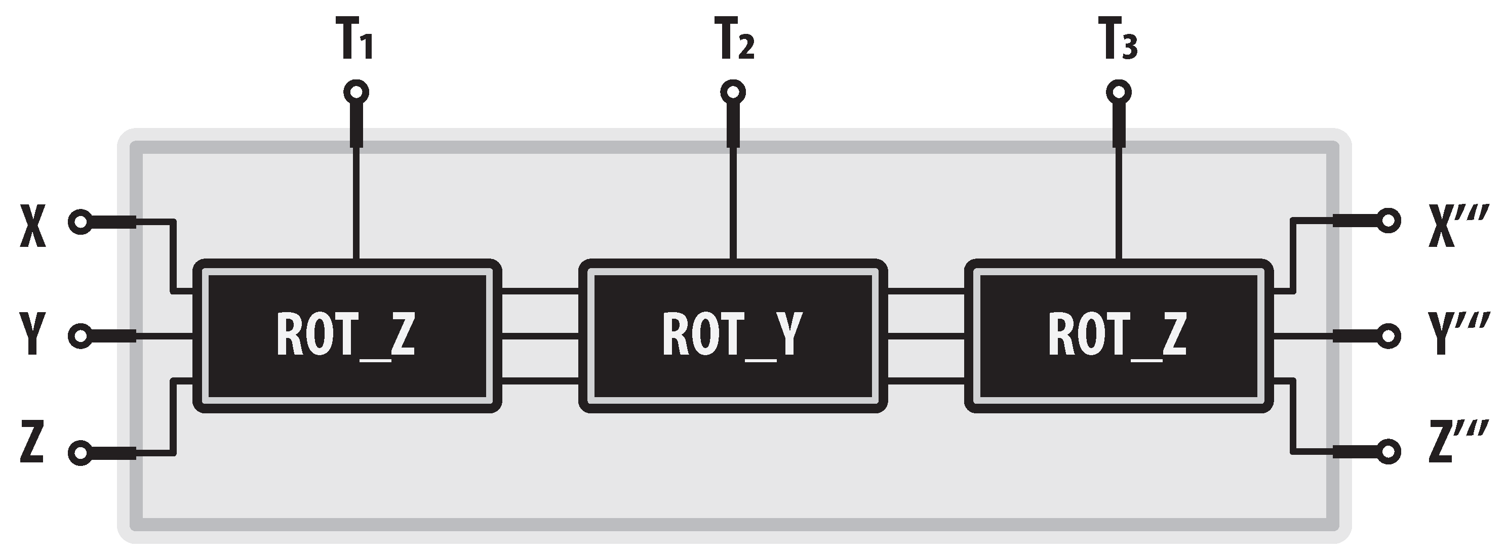
Finally, using modules shown in Figure 11, we can compute the final orientation of the gimbal mechanism as exhibited below in Figure 12.
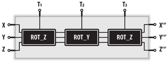
Figure 12.
Orientation module for the gimbal mechanism.
In order to compare the classical and rational methods, we contrast how many operations are involved for each one, as shown in Table 3 and Table 4. Although , , and square root are transcendental functions, we treated them separately due to the complexity that each one requires for its calculation in hardware.
Table 3.
Number of operations for each rotation computation.
Table 4.
Total number of operations for orientation computing.
7. Conclusions
Rational trigonometry provides an efficient alternative to represent rotations in space using quaternions. The implementations we made are more compact than those that would result from implementing the calculation of the orientation using rotation matrices and the CORDIC algorithm.
The use of rational trigonometry eases the computation of orientation, since there are no transcendental functions involved. Using quaternions in the rational form leads to an efficient and compact description of any robotic mechanism in real life. However, the only drawback is that we cannot parameterize a joint range of , since the behavior of the “half-turn” is asymptotic. Still, with a relatively low number of bits, we can describe joint ranges greater than (e.g., 7 ). Therefore, for practical applications, the proposed model is very useful. It is essential to point out that an architecture with more bits, e.g., 32 bits, would be required to improve the computation accuracy of the orientation.
The first model, called the “gimbal mechanism”, was simulated in GeoGebra software and implemented on an Arduino microcontroller to prove its operation. The second model, “wrist mechanism”, was also simulated in GeoGebra and implemented on an Arduino to verify its operation. Only the first model was implemented in hardware to compare the number of logic elements between classical and rational implementations. Both models are the continuation of research carried out by the authors [32], where some rational algorithms were obtained for calculating the direct and inverse kinematic for robotic mechanisms, showing that in a hardware implementation, these algorithms are more efficient.
Author Contributions
Methodology and investigation, R.M.; formal analysis and supervision, E.Z.; funding acquisition, H.S.; visualization, writing—review and editing, F.A.; writing, L.A.S. All authors have read and agreed to the published version of the manuscript.
Funding
This work was economically supported by the Instituto Politécnico Nacional under projects: 20200630, 20200651, 20210316, 20210788, 20220226, and 20220002, and CONACYT under projects 65 (Fronteras de la Ciencia) and 6005 (FORDECYT-PRONACES).
Institutional Review Board Statement
Not applicable.
Informed Consent Statement
Not applicable.
Data Availability Statement
Not applicable.
Acknowledgments
E.Z. and H.S. would like to acknowledge the support provided by CIC-IPN in carrying out this research, and F.A. would like to thank the Centro de Investigaciones en Óptica A.C. The first author thanks CONACYT for the scholarship granted towards pursuing his PhD studies.
Conflicts of Interest
The authors declare no conflict of interest.
Appendix A
In rational theory, there are some fundamental concepts; for instance, quadrance measures the separation between two points. The quadrance between the points and is the number:
where , , and are the coordinates of points and , respectively, and they are rational numbers or even real numbers. By making a relationship between classical and rational trigonometry, the quadrance can be seen as the square of the Euclidean distance:
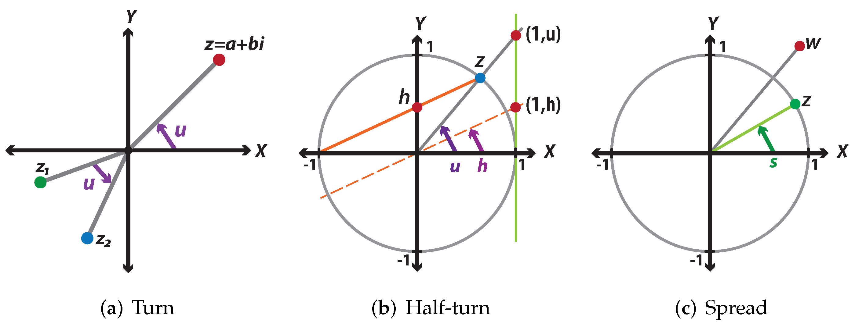
Since the quadrance is the rational analog for distance, it makes sense to wonder, what is the rational analog for angle notion? The answer includes three rational replacements for angle, which are spread, turn, and half-turn. We only focus on the turn and half-turn in developing our experiments. Figure A1 compares these three rational measures for rotations in the plane.
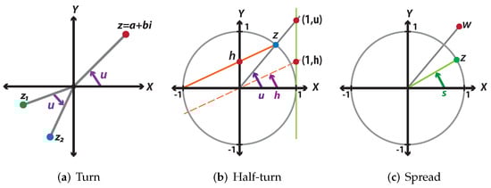
Figure A1.
Rational analogs for angle.
Figure A1.
Rational analogs for angle.
Let be a complex number and be its complex conjugate, where and . We can define the quadrance of z by:
The definitions of the rational replacements for angle are explained as follows:
Turn: The turn of any complex number z is defined as:
In a more general case, to compute the turn between two different complex numbers and as shown in Figure A1a, we need to apply:
Half-turn: For any complex number z on the unit circle, except the point , the half-turn is the intersection between the y-axis and the line through the points and z, as shown in Figure A1b. Therefore, the half-turn is defined by:
In order to make an analogy between turns and half-turns, we will translate the orange line from the point to the origin, as presented in Figure A1b. Notice that the separation between the points and the x- is exactly half of the separation between the points and the x-. This is true for any complex number on the unit circle, except the point , and this is the reason why these parameters are called turns and half-turns.
Spread: The spread can be defined in several ways. According to Figure A1c, the spread is determined by:
where z is a unit complex number and . However, in a more general way, the spread can be specified for any complex number by the next expression:
Rotations on the Plane
For every , we may associate a rotation given by:
and in the same way, for each rotation, we can assign a complex number.
As in a stereographic projection, we make a rational parameterization for a circle:
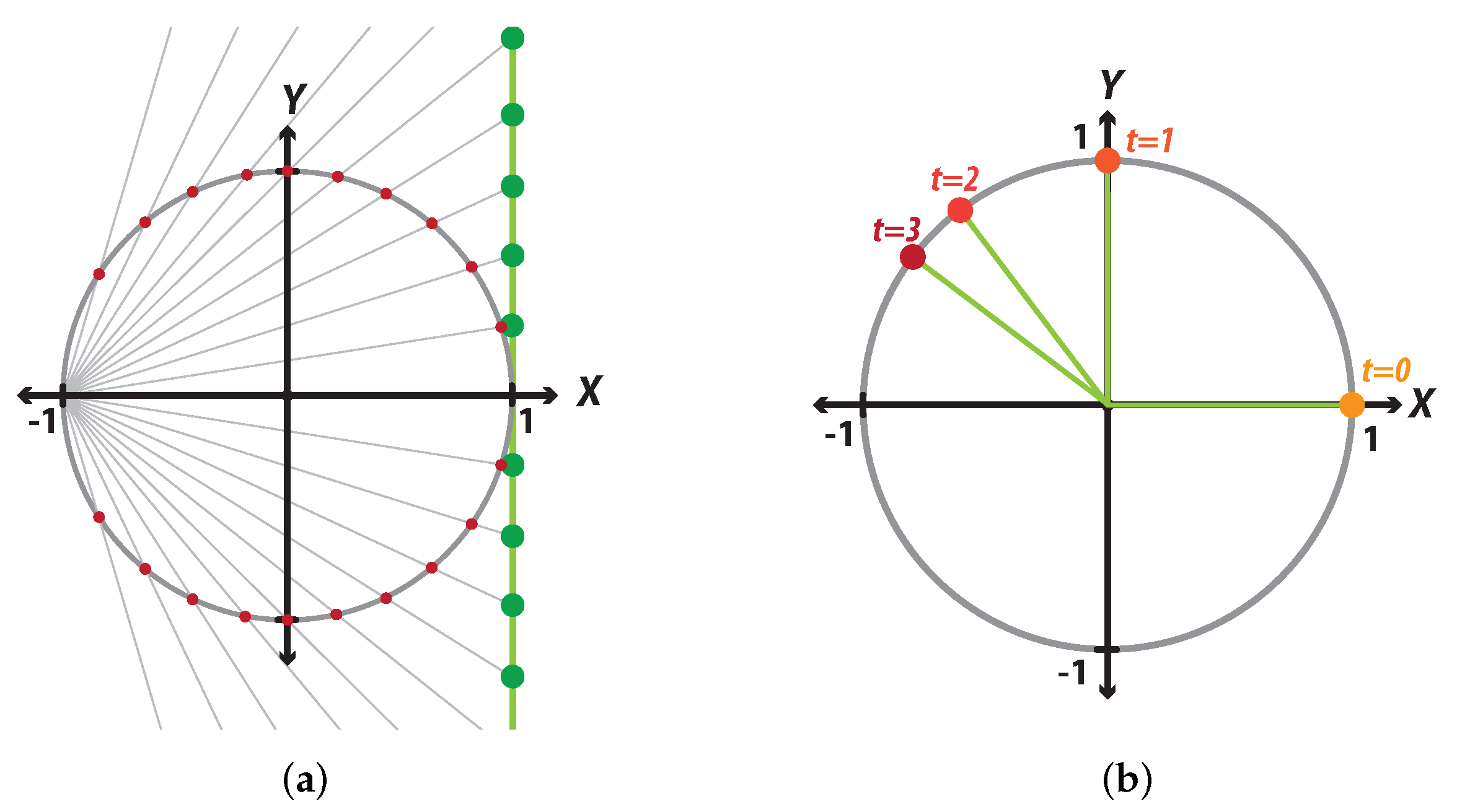
Figure A2a represents the stereographic projection in the complex plane of the circumference, centered at the origin with a radius equal to 1 on the straight-line . According to Equation (A7), is defined as the point , resulting from the intersection between the y-axis and the line that goes from the point to the point . On the other hand, can be described geometrically as the point of coordinates from the intersection between the line that goes from the center of the circumference to the point and the line . Finally, if we move the orange line, created when defining , to the origin of the coordinates, we observe that the intersection of this line and the straight line occurs at the point . In summary, Figure A2a shows the stereographic projection of the circle on the complex line , and Figure A2b displays the values obtained with the rational parameterization of the circumference using Equation (A10).
Additionally, as shown in Figure A2a, every point on the unit circle, except the point , can be mapped over the line , and every point on the line can be associated with only one point on the unit circle, where h is the parameter half-turn defined above. The point is the only one that does not have a projection on the line, since this point can correspond to , depending on the direction from which you approach the point. The rational parameterization of the circle, according to Equation (A10), lets us describe almost any point of a circle with radius one, centered on the point , as presented in Figure A2b. This parameterization will help us to develop the quaternions in a rational way.
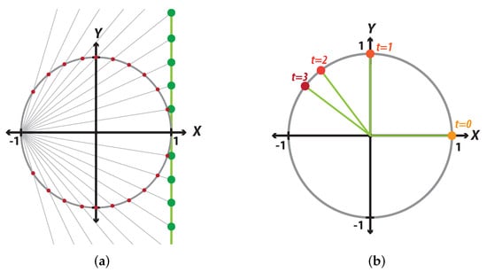
Figure A2.
Rational parameterization of the unit circle. (a) Representation of the stereographic projection for the unit circumference. (b) Some points on the unit circle according to the half-turn parameter.
Figure A2.
Rational parameterization of the unit circle. (a) Representation of the stereographic projection for the unit circumference. (b) Some points on the unit circle according to the half-turn parameter.
Example: Find the points on the unit circle when , Figure A2b:
References
- Arrigo, J.; Chau, P. Accurate motion capture at high rotational rates using the CORDIC algorithm. In Proceedings of the Thrity-Seventh Asilomar Conference on Signals, Systems and Computers, Pacific Grove, CA, USA, 9–12 November 2003; Volume 2, pp. 2203–2207. [Google Scholar]
- Lang, T.; Antelo, E. High-throughput 3D rotations and normalizations. In Proceedings of the Conference Record of Thirty-Fifth Asilomar Conference on Signals, Systems and Computers (Cat. No. 01CH37256), Pacific Grove, CA, USA, 4–9 November 2001; Volume 1, pp. 846–851. [Google Scholar]
- Biswas, D.; Ye, Z.; Mazomenos, E.B.; Jöbges, M.; Maharatna, K. CORDIC framework for quaternion-based joint angle computation to classify arm movements. In Proceedings of the 2018 IEEE International Symposium on Circuits and Systems (ISCAS), Vancouver, BC, Canada, 23–26 May 2018; pp. 1–5. [Google Scholar]
- Arrigo, J.F.; Chau, P.M. Power aware attitude computation during rapid rotational motion. IEEE Trans. Instrum. Meas. 2006, 55, 63–69. [Google Scholar] [CrossRef]
- Osborne, J.; Hicks, G.; Fuentes, R. Global analysis of the double-gimbal mechanism. IEEE Control Syst. Mag. 2008, 28, 44–64. [Google Scholar]
- Ahi, B.; Nobakhti, A. Hardware implementation of an ADRC controller on a gimbal mechanism. IEEE Trans. Control Syst. Technol. 2017, 26, 2268–2275. [Google Scholar] [CrossRef]
- Choi, C.L.; Rebello, J.; Koppel, L.; Ganti, P.; Das, A.; Waslander, S.L. Encoderless gimbal calibration of dynamic multi-camera clusters. In Proceedings of the IEEE International Conference on Robotics and Automation (ICRA), Brisbane, Australia, 21–25 May 2018; pp. 2126–2133. [Google Scholar]
- Rajesh, R.; Kavitha, P. Camera gimbal stabilization using conventional PID controller and evolutionary algorithms. In Proceedings of the 2015 International Conference on Computer, Communication and Control (IC4), Indore, India, 10–12 September 2015; pp. 1–6. [Google Scholar]
- Lo, Y.L.; Li, Y.C.; Kim, Y.C. Downstream interference effect of low-Scruton-number high-rise buildings under turbulent boundary layer flow. J. Wind Eng. Ind. Aerodyn. 2020, 198, 104101. [Google Scholar] [CrossRef]
- Altan, A.; Hacıoğlu, R. Model predictive control of three-axis gimbal system mounted on UAV for real-time target tracking under external disturbances. Mech. Syst. Signal Process. 2020, 138, 106548. [Google Scholar] [CrossRef]
- Zheng, P.; Tan, X.; Kocer, B.B.; Yang, E.; Kovac, M. TiltDrone: A Fully-Actuated Tilting Quadrotor Platform. IEEE Robot. Autom. Lett. 2020, 5, 6845–6852. [Google Scholar] [CrossRef]
- Craig, J.J. Introduction to Robotics: Mechanics and Control; Pearson Educacion: London, UK, 2005. [Google Scholar]
- Fu, Z.; Pan, J.; Spyrakos-Papastavridis, E.; Chen, X.; Li, M. A Dual Quaternion-Based Approach for Coordinate Calibration of Dual Robots in Collaborative Motion. IEEE Robot. Autom. Lett. 2020, 5, 4086–4093. [Google Scholar] [CrossRef]
- Rodman, L. Topics in quaternion linear algebra. In Topics in Quaternion Linear Algebra; Princeton University Press: Princeton, NJ, USA, 2014. [Google Scholar]
- Morais, J.P.; Georgiev, S.; Sprößig, W. Real Quaternionic Calculus Handbook; Springer: Berlin/Heidelberg, Germany, 2014. [Google Scholar]
- Kavan, L.; Collins, S.; O’Sullivan, C.; Zara, J. Dual Quaternions for Rigid Transformation Blending; Technical report; Trinity College Dublin: Dublin, Ireland, 2006. [Google Scholar]
- Ma, R.; Gupta, K.C. On the motion of oblique bevel geared robot wrists. J. Robot. Syst. 1989, 6, 509–520. [Google Scholar] [CrossRef]
- Zhang, H. Feasibility analysis of displacement trajectories for robot manipulators with a spherical wrist. In Proceedings of the 1991 IEEE International Conference on Robotics and Automation, Sacramento, CA, USA, 9–11 April 1991; pp. 1252–1257. [Google Scholar]
- Jo, H.M.; Lim, D.J.; Chung, W.J.; Choi, J.K.; Kim, D.Y.; Ahn, Y.J.; Ahn, H.S. Optimal wrist design of wrist-hollow type 6-axis articulated robot using genetic algorithm. In Proceedings of the 2018 IEEE International Conference on Mechatronics and Automation (ICMA), Jilin, China, 5–8 August 2018; pp. 1486–1491. [Google Scholar]
- Bailly, F.; Charbonneau, E.; Danès, L.; Begon, M. Optimal 3D arm strategies for maximizing twist rotation during somersault of a rigid-body model. Multibody Syst. Dyn. 2021, 52, 193–209. [Google Scholar] [CrossRef]
- Chu, C.Y.; Xu, J.Y.; Lan, C.C. Design and experiment of a compact wrist mechanism with high torque density. Mech. Mach. Theory 2014, 78, 65–80. [Google Scholar] [CrossRef]
- Cheng, L.; Wang, H.; Liu, Y. Movement coupling analysis on the wrist of 165Kg spot welding robot. In Proceedings of the 2011 IEEE International Conference on Cyber Technology in Automation, Control, and Intelligent Systems, Kunming, China, 20–23 May 2011; pp. 244–248. [Google Scholar]
- Hildenbrand, D. Foundations of geometric algebra computing. In Proceedings of the AIP Conference Proceedings, Ft. Worth, TX, USA, 5–10 August 2012; American Institute of Physics: College Park, MD, USA; Volume 1479, pp. 27–30. [Google Scholar]
- Cao, Y.; Ji, W.; Li, Z.; Zhou, H.; Liu, M. Orientation-singularity and nonsingular orientation-workspace analyses of the stewart-gough platform using unit quaternion representation. In Proceedings of the 2010 Chinese Control and Decision Conference, Xuzhou, China, 26–28 May 2010; pp. 2282–2287. [Google Scholar]
- Wang, C.; Fu, Z. A new way to detect the position and orientation of the wheeled mobile robot on the image plane. In Proceedings of the IEEE International Conference on Robotics and Biomimetics (ROBIO 2014), Bali, Indonesia, 5–10 December 2014; pp. 2158–2162. [Google Scholar]
- Paulraj, M.; Ahmad, R.B.; Hema, C.; Hashim, F.; Yusoff, S. Active stereo vision based system for estimation of mobile robot orientation using affine moment invariants. In Proceedings of the 2008 International Conference on Electronic Design, Penang, Malaysia, 1–3 December 2008; pp. 1–7. [Google Scholar]
- Wildberger, N. A rational approach to trigonometry. Math Horizons 2007, 15, 16–20. [Google Scholar] [CrossRef]
- Wildberger, N.J. Divine Proportions: Rational Trigonometry to Universal Geometry; Wild Egg: Sydney, Australia, 2005. [Google Scholar]
- Jia, Y.B. Quaternions and rotations. Com. S 2008, 477, 15. [Google Scholar]
- Kenwright, B. A beginners guide to dual-quaternions: What they are, how they work, and how to use them for 3D character hierarchies. In Proceedings of the 20th International Conference in Central Europe on Computer Graphics, Visualization and Computer Vision 2012, Plzen, Czech Republic, 26–28 June 2012; pp. 1–10. [Google Scholar]
- Paul, R.P. Robot Manipulators: Mathematics, Programming, and Control: The Computer Control of Robot Manipulators; The MIT Press: Cambridge, MA, USA, 1981. [Google Scholar]
- Peralta, R.M.; Gómez, E.Z.; Azuela, J.H.S. Efficient FPGA hardware implementation for robot manipulator kinematic modeling using rational trigonometry. IEEE Lat. Am. Trans. 2019, 17, 1524–1536. [Google Scholar] [CrossRef]


Publisher’s Note: MDPI stays neutral with regard to jurisdictional claims in published maps and institutional affiliations. |
© 2022 by the authors. Licensee MDPI, Basel, Switzerland. This article is an open access article distributed under the terms and conditions of the Creative Commons Attribution (CC BY) license (https://creativecommons.org/licenses/by/4.0/).