
Control and Dynamic Characteristics Analysis for the Double-Compound Axial Piston Pump Based on Working Conditions


Abstract
:1. Introduction
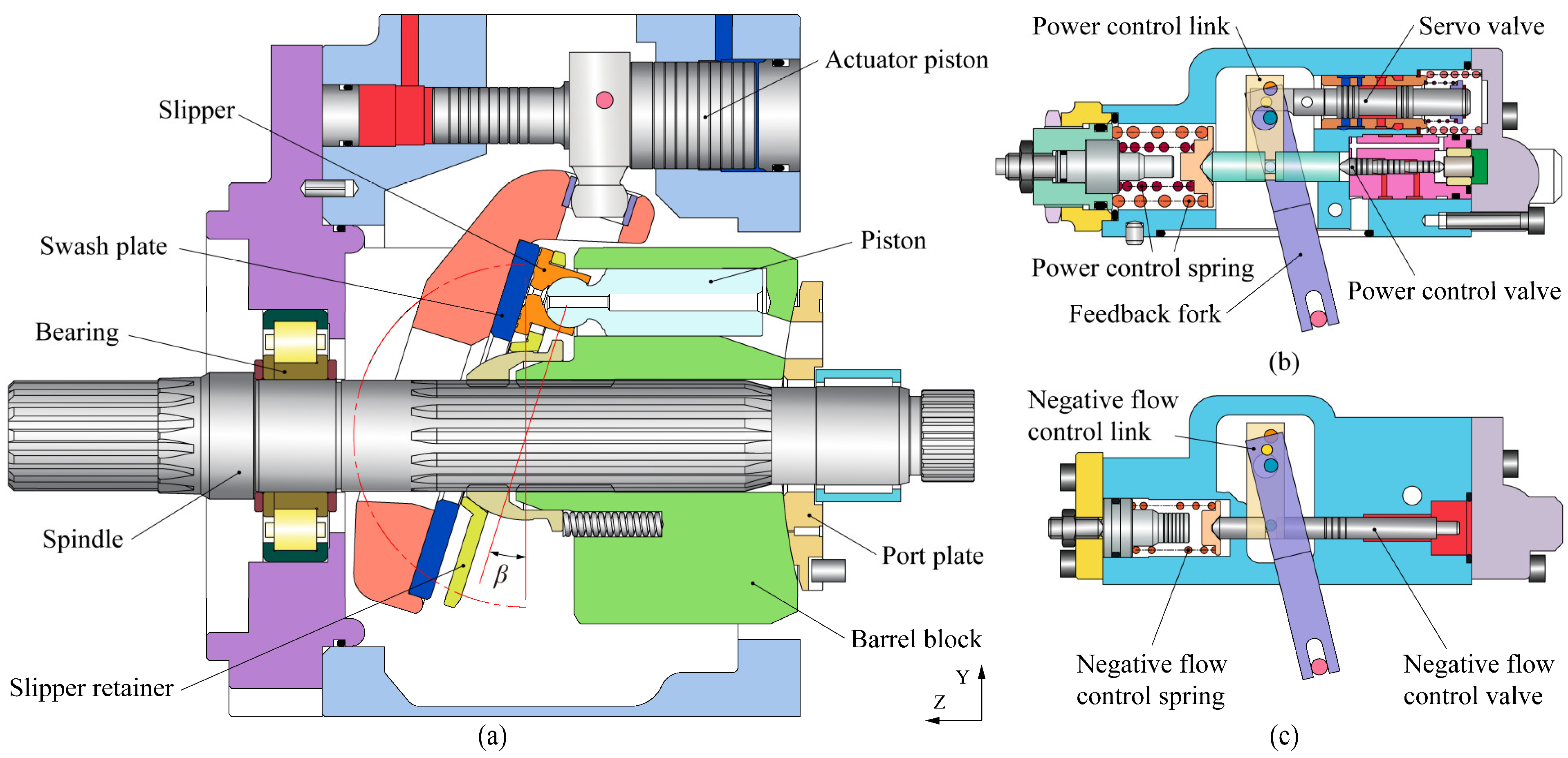
2. Description of Physical System
3. Numerical Model of the Double-Compound Axial Piston Pump
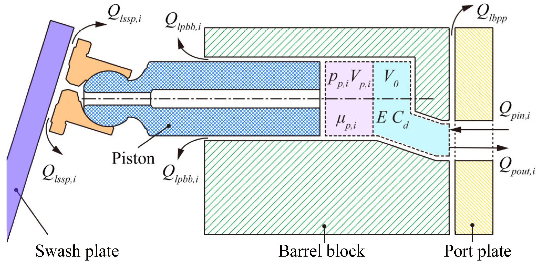
3.1. Dynamic Model of Axial Piston Pump Body
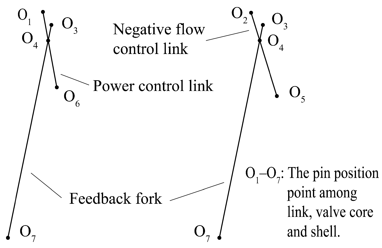
3.2. Model of Swash Plate Variable Displacement Control
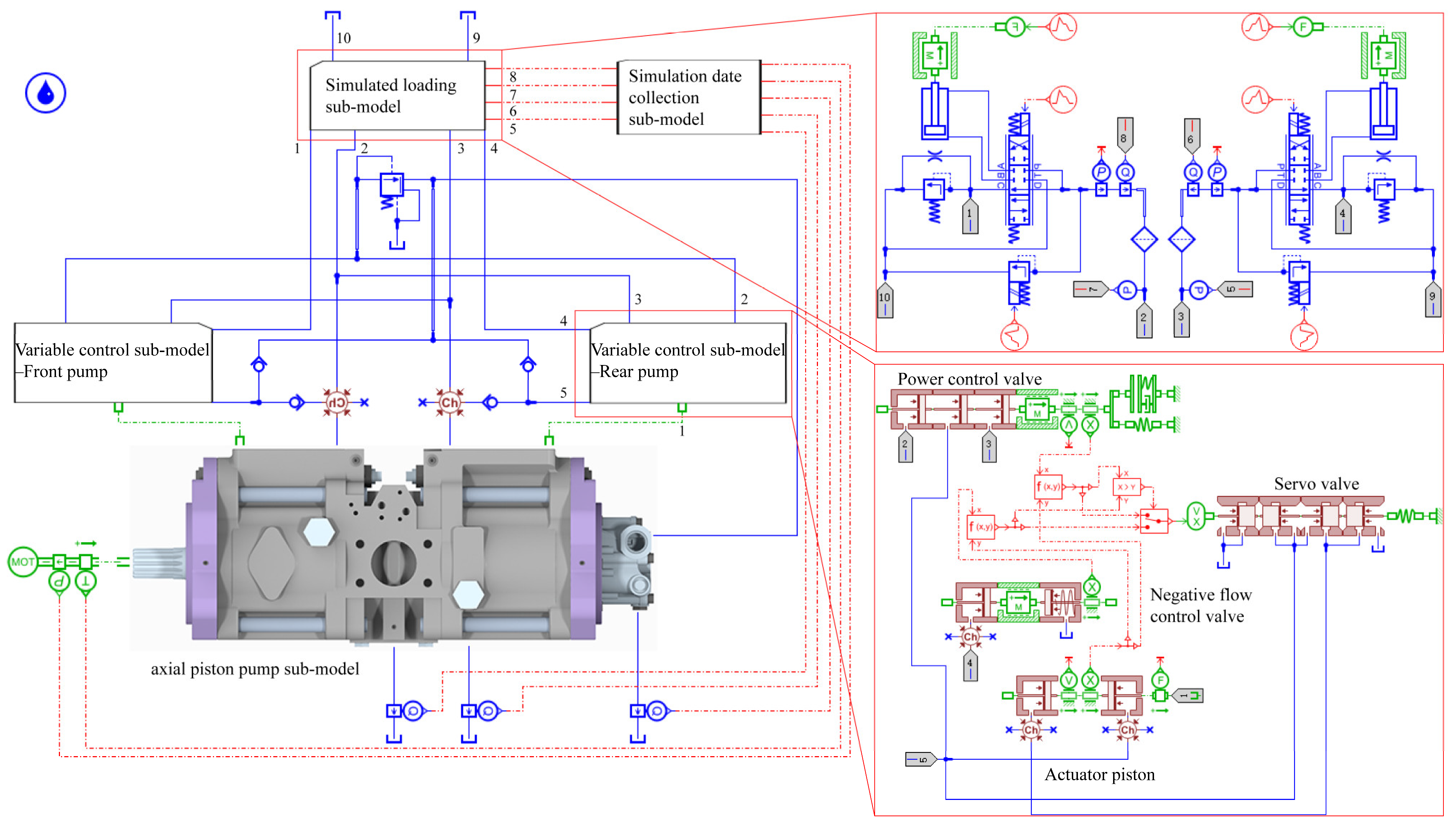
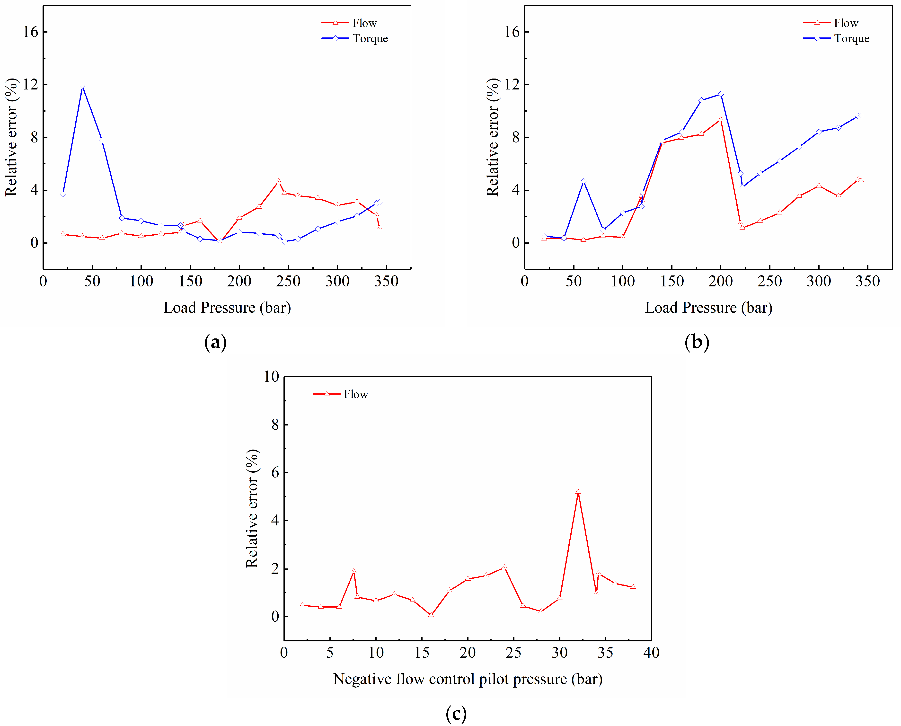
4. Numerical Simulation Model and Experimental Verification
5. Analysis of Control Characteristics of the Double-Compound Axial Piston Pump
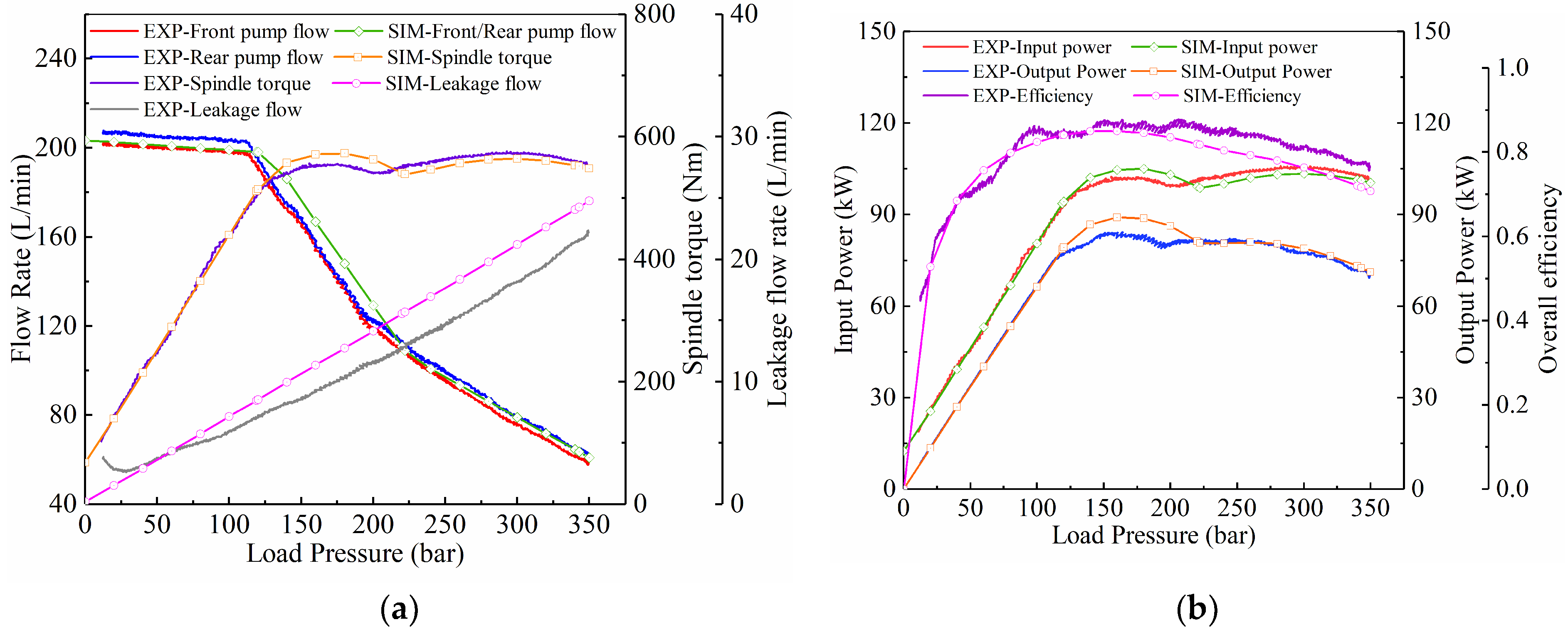
5.1. Analysis of Constant Power Control Characteristics
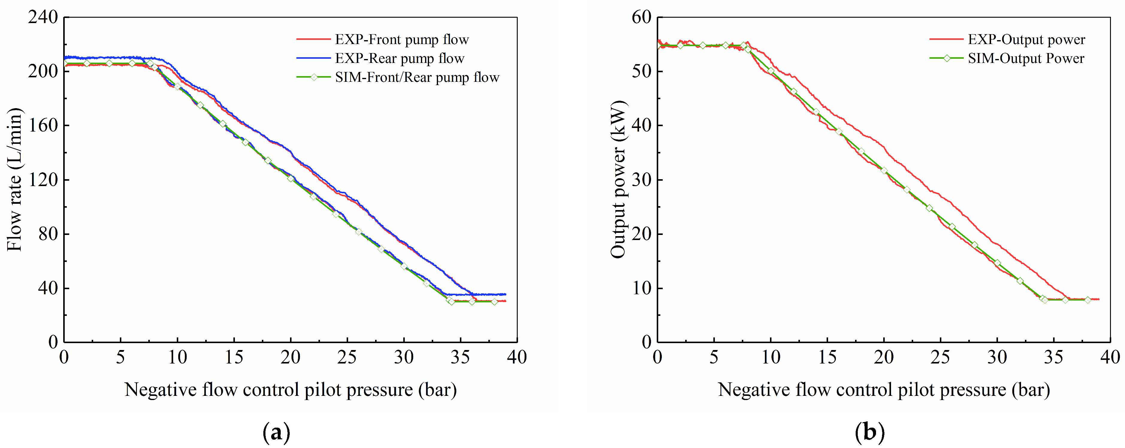
5.2. Analysis of Variable Power Control Characteristics
6. Dynamic Characteristics Analysis of the Double-Compound Axial Piston Pump
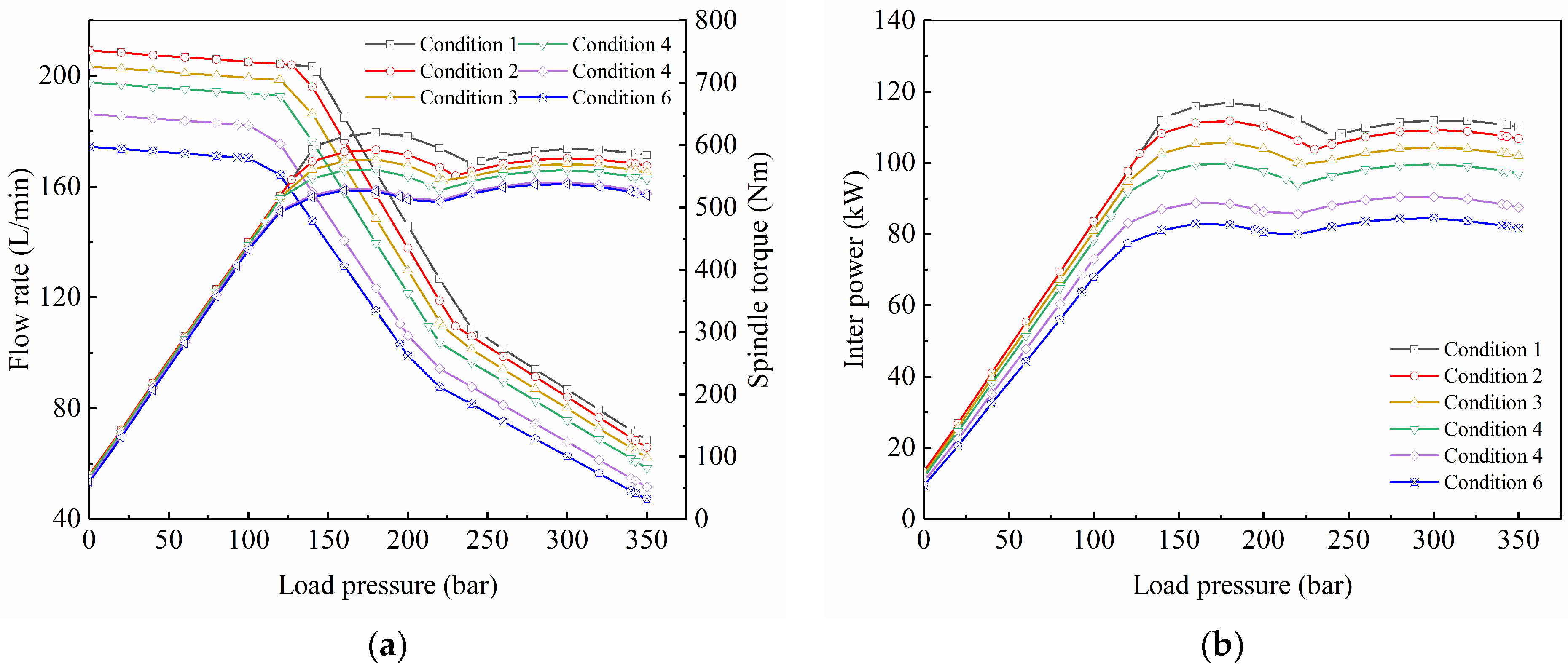
6.1. Influence of Load Pressure on Dynamic Characteristics
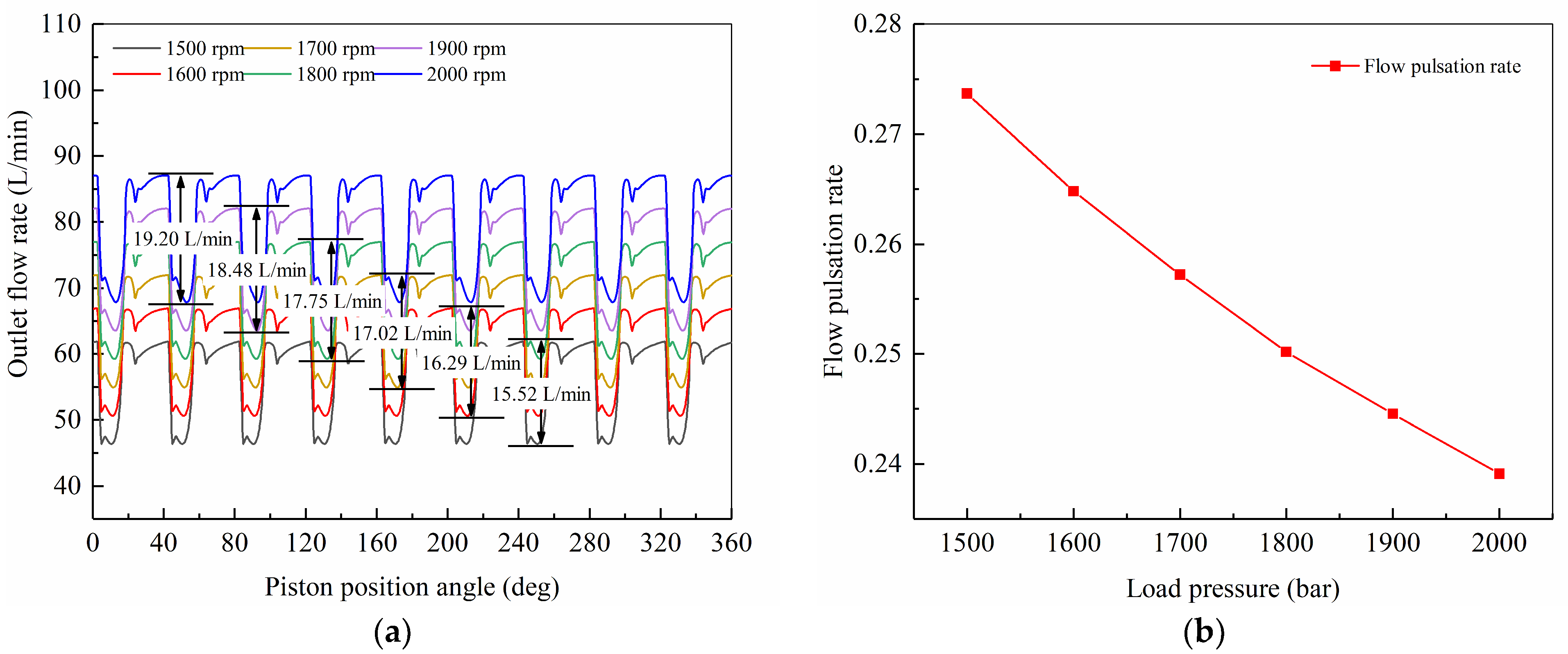
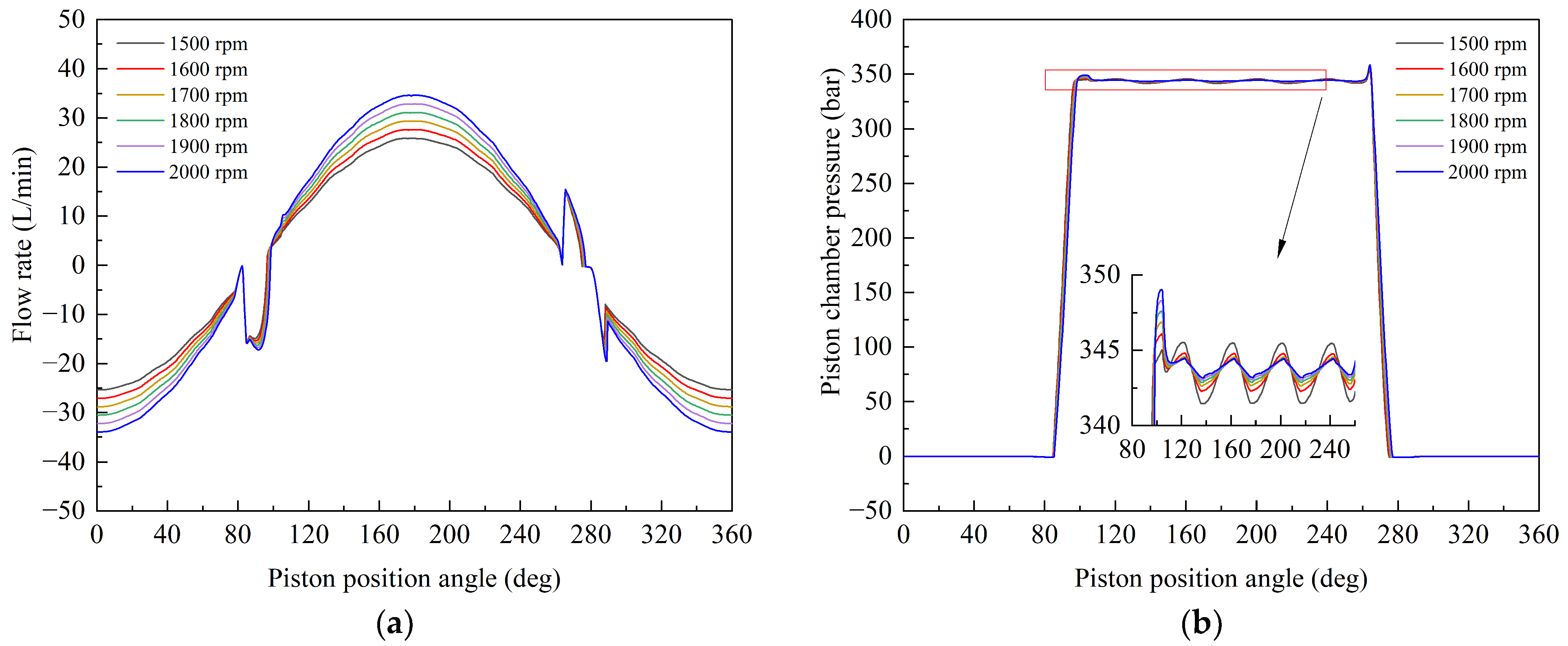
6.2. Influence of Spindle Speed on Dynamic Characteristics
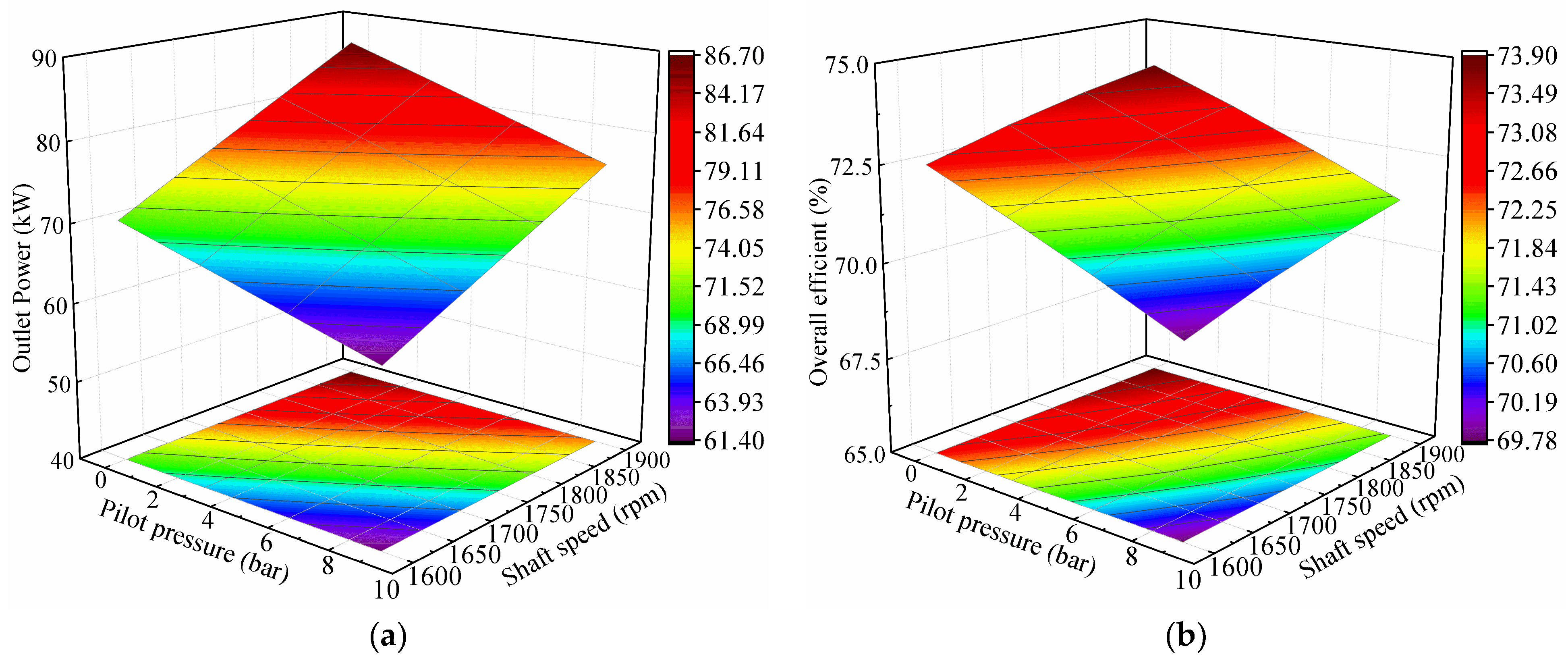
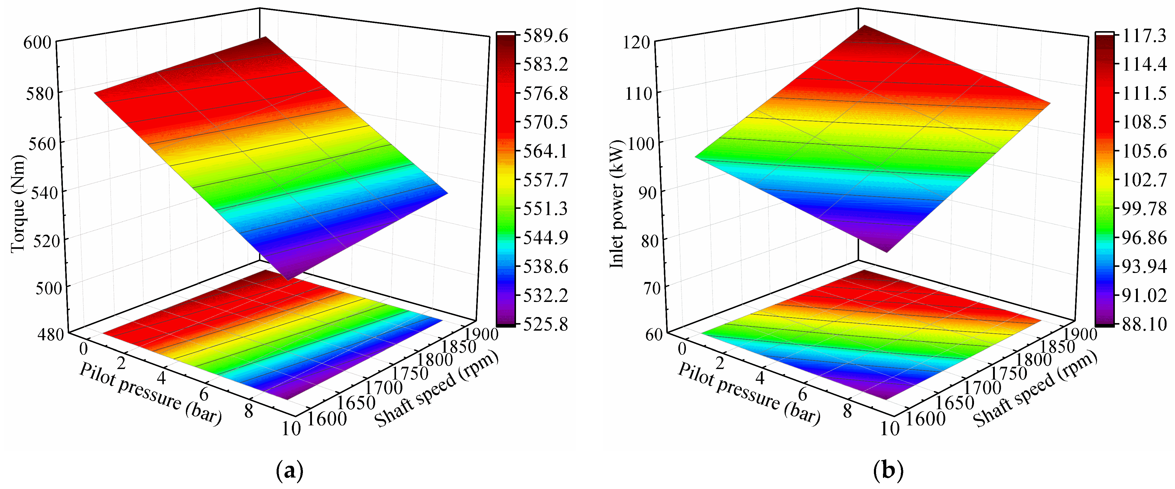
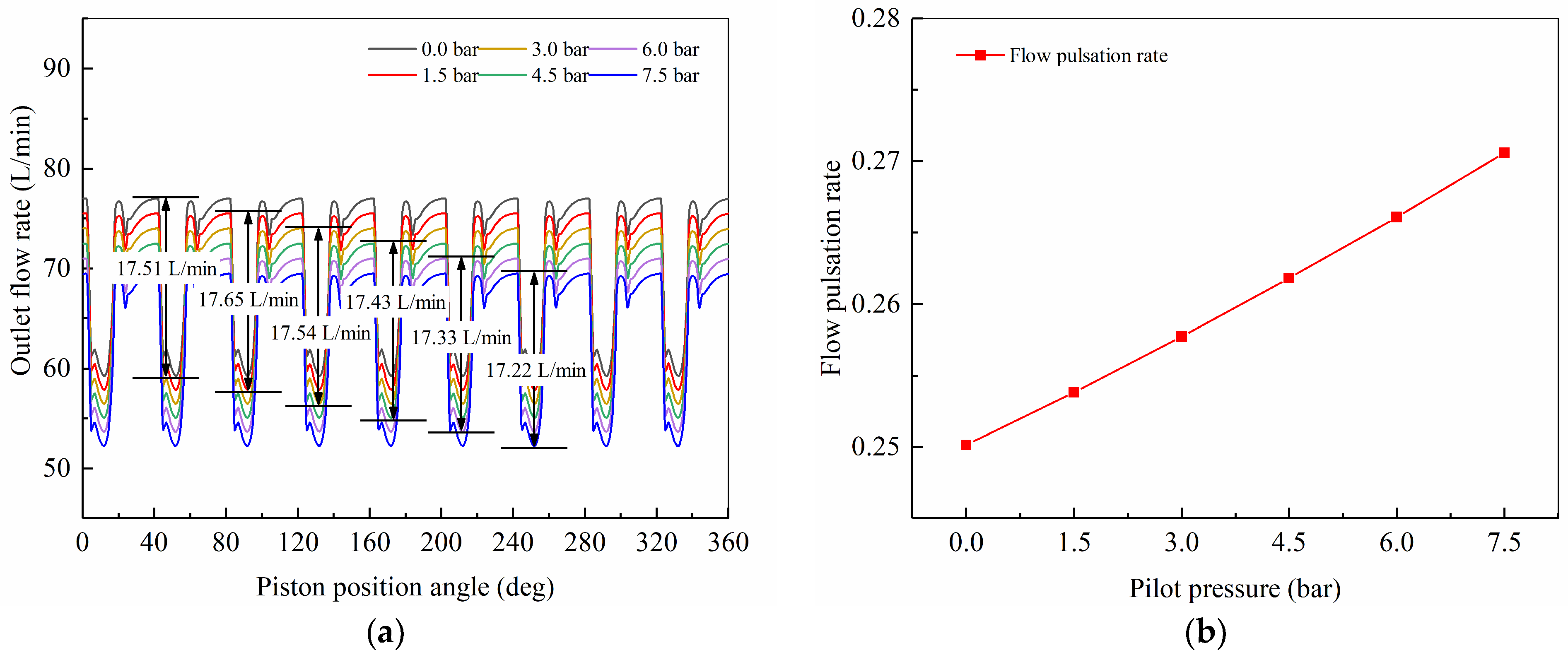
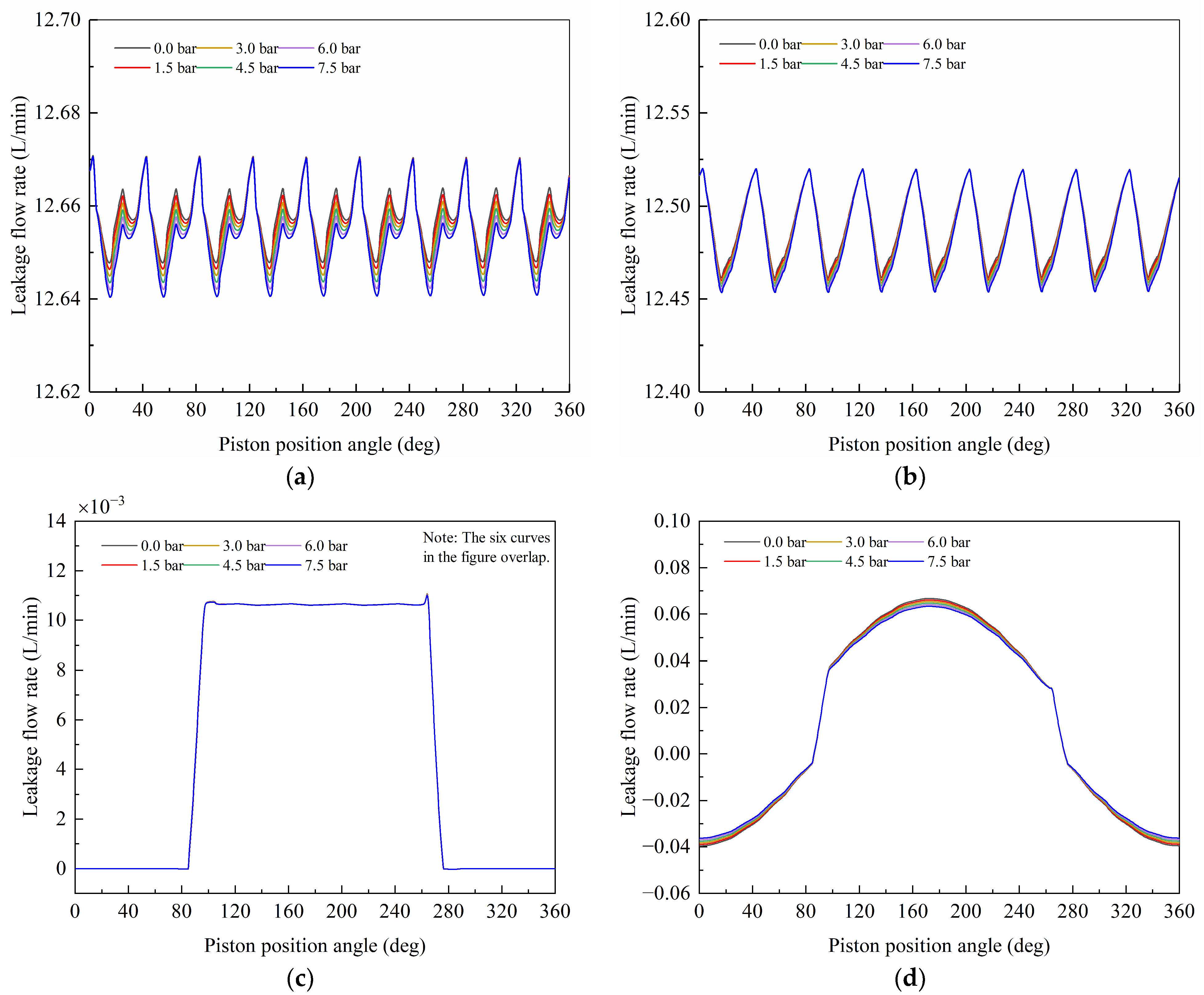
6.3. Influence of Power Control Pilot Pressure on Dynamic Characteristics
7. Conclusions
Author Contributions
Funding
Institutional Review Board Statement
Informed Consent Statement
Data Availability Statement
Conflicts of Interest
Nomenclature
| Ad, Ax | action area of large cavity and action area of small cavity of the actuator piston (m2) |
| Af | effective area of the power control pilot pressure acting on the power control valve (m2) |
| Ancv | effective area of the pilot control pressure acting on the negative flow control valve (m2) |
| Apcv1, Apcv2 | effective area of load pressure of the front/rear pump acting on power control valve (m2) |
| Apin,i, Apout,i | flow area between the inlet/outlet main groove and the ith piston chamber (m2) |
| cap | damping coefficient of the actuator piston (N/(m/s)) |
| cncv | damping coefficient of the negative flow control valve (N/(m/s)) |
| cpcv | damping coefficient of the power control valve (N/(m/s)) |
| csp | damping coefficient of the swash plate (N/(m/s)) |
| csv | damping coefficient of the servo valve (N/(m/s)) |
| Cd | flow coefficient |
| dp | piston diameter (m) |
| dtp | diameter of the piston damping orifice (m) |
| E | bulk modulus of the hydraulic oil (MPa) |
| ep | eccentricity distance between the piston and the piston chamber (m) |
| Fncv0 | spring preload of the negative flow control valve (N) |
| Fp,i | equivalent force of the oil pressure on piston (N) |
| Fpcv0 | spring preload of the power control valve (N) |
| Fpty,i, Fptz,i | projections of the resultant force Fpt,i on the z and y axis (N) |
| Fsp | force of the swash plate on the actuator piston (N) |
| Fsv0 | spring preload of the servo valve (N) |
| Fvlpc,i | viscous friction caused by leakage of the piston–barrel block pair (N) |
| Fvlsy,i, Fvlsz,i | projections of the resultant force Fvls,i on the z and y axis (N) |
| hp | diameter gap between the piston and the piston chamber (m) |
| hppb | gap between the barrel block and the port plate (m) |
| hssp | gap between the slipper and the swash plate (m) |
| J1 | moment of inertia of the power control link around O1 (kg·m2) |
| J2 | moment of inertia of the negative flow control link around O2 (kg·m2) |
| Jf4, Jf7 | moment of inertia of feedback fork around O4/O7 (kg·m2) |
| Jsp | moment of inertia of the swash plate (kg·m2) |
| k1, k2 | spring stiffness of the outer–inner spring of the power control valve (N/m) |
| kncv | spring stiffness of the negative flow control valve (N/m) |
| kpcv | spring stiffness of power control valve (N/m) |
| ksv | spring stiffness of servo valve (N/m) |
| lpc,i | contact length between the piston and the piston chamber (m) |
| Lsp | acting force arm of the actuator piston to the swash plate (m) |
| ltp | length of piston damping orifice (m) |
| map | mass of the actuator piston (kg) |
| mncv | mass of the negative flow control valve core (kg) |
| mpcv | mass of the power control valve core (kg) |
| msv | mass of the servo valve core (kg) |
| pap | pressure of the large cavity of the actuator piston (MPa) |
| pc | pressure of leakage cavity (MPa) |
| pd | pump outlet pressure (MPa) |
| pf | power control pilot pressure (MPa) |
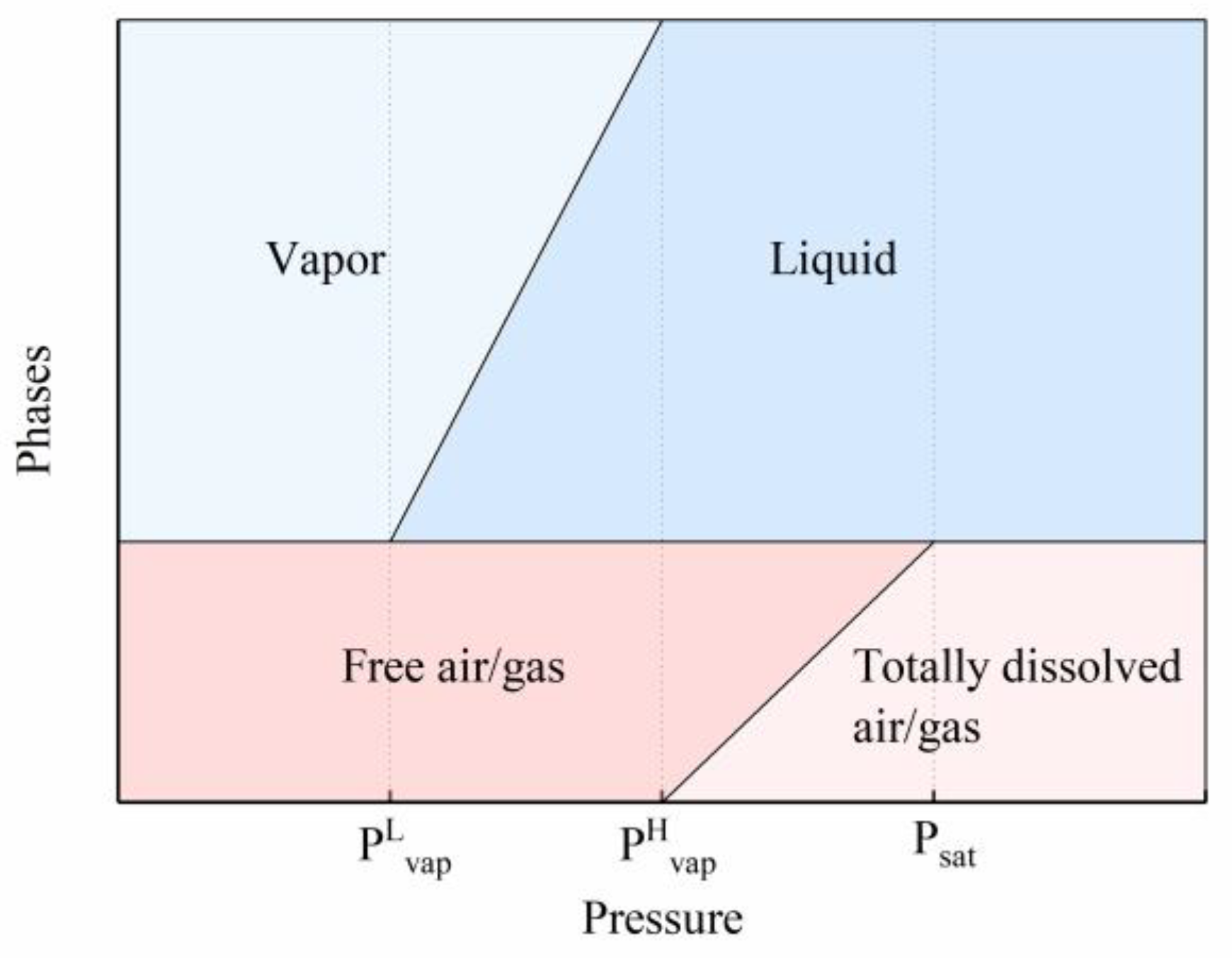
| PHvap, PLvap | high/low-saturation vapor pressure (MPa) |
| pncv | negative flow control pilot pressure (MPa) |
| pp,i | pressure of piston chamber (MPa) |
| ps | pump inlet pressure (MPa) |
| Psat | saturation pressure (MPa) |
| Ql | total leakage flow (L/min) |
| Qlpbb,i | leakage flow of the piston–barrel block pair (L/min) |
| Qlppb | leakage flow of the port plate–barrel block pair (L/min) |
| Qlssp,i | leakage flow of the slipper–swash plate pair (L/min) |
| Qpin,i, Qpout,i | inlet/outlet flow of piston chamber (L/min) |
| R | piston distribution radius (m) |
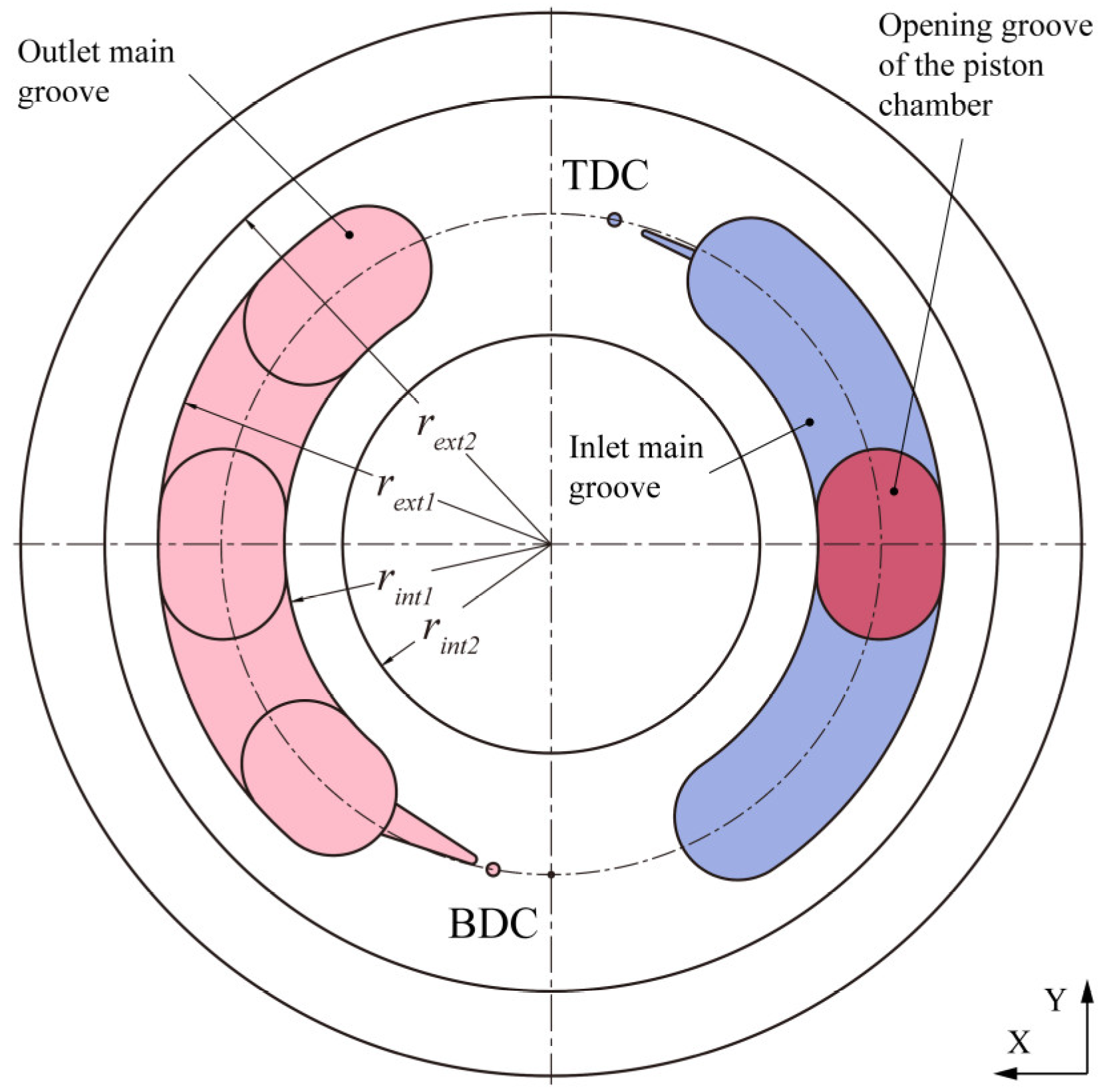
| rext1, rext2 | inner/outer radius of the external port plate (m) |
| rint1, rint2 | outer/inner radius of the internal port plate (m) |
| rspi, rspo | inner/outer radius of the slipper (m) |
| Tsf | spindle torque of piston pump (N·m) |
| Tsp | torque applied by the piston to the swash plate (N·m) |
| Tvlpp | viscous friction torque between the port plate and the barrel block (N·m) |
| up,i | Couette effect of the piston speed on the leakage flow (m/s) |
| V0 | structure dead volume of the piston chamber (m3) |
| Vap | volume of the large cavity of the actuator piston (m3) |
| Vp,i | volume of piston chamber (m3) |
| ω | rotational speed of the spindle (rad/s) |
| wsv | flow area of the servo valve (m2) |
| x0 | distance difference between zero position of double springs of the power control valve (m) |
| xap | displacement of the actuator piston (m) |
| xcvf | feedback displacement of the servo valve (m) |
| xlim | maximum displacement of the power control valve core (m) |
| xpcv | displacement of the power control valve core (m) |
| xsv | displacement of the servo valve (m) |
| yp,i | force arm of the resultant force along the z axis in the y direction (m) |
| zp,i | force arm of the resultant force along the y axis in the z direction (m) |
| β | inclination angle of the port plate (rad) |
| θin, θout | angle range of the inlet/outlet main groove of the port plate (rad) |
| μ | dynamic viscosity (kg/m·s) |
| μp,i | dynamic viscosity of the piston–barrel block pair gap (kg/m·s) |
References
- Jong, K.; Jae, Y. Measurement of Fluid film thickness on the Valve Plate in Oil Hydraulic Axial Piston Pumps (I)—Bearing Pad Effects. J. Mech. Sci. Technol. 2003, 17, 246–253. [Google Scholar]
- Kim, J.-K.; Kim, H.-E.; Lee, Y.-B.; Youn, J.J.; Oh, S.-H. Measurment of Fluid Film Thickness on The Valve Plate in Oil Hydraulic Axial Piston Pumps (Part II Spherical Design Effects). J. Mech. Sci. Technol. 2005, 19, 655–663. [Google Scholar] [CrossRef]
- Cho, I.S.; Jung, J. A study on the pressure ripple characteristics in a bent-axis type oil hydraulic piston pump. J. Mech. Sci. Technol. 2013, 27, 3713–3719. [Google Scholar] [CrossRef]
- Cho, I.S. A study on the optimum design for the valve plate of a swash plate-type oil hydraulic piston pump. J. Mech. Sci. Technol. 2015, 29, 2409–2413. [Google Scholar] [CrossRef]
- Shin, J.H. Computational study on dynamic pressure in a swash-plate axial piston pump connected to a hydraulic line with an end resistance. J. Mech. Sci. Technol. 2015, 29, 2381–2390. [Google Scholar] [CrossRef]
- Stosiak, M. The impact of hydraulic systems on the human being and the environment. J. Theor. Appl. Mech. 2015, 53, 409–420. [Google Scholar] [CrossRef] [Green Version]
- Kudzma, Z.; Stosiak, M. Reduction of infrasounds in machines with hydrostatic drive. Acta Bioeng. Biomech. 2013, 15, 51–64. [Google Scholar] [CrossRef]
- Kim, J.-K.; Kim, H.-E.; Youn, J.J.; Oh, S.-H.; Jung, S.-H. Relation between Pressure Variations and Noise in Axial Type Oil Piston Pumps. J. Mech. Sci. Technol. 2004, 18, 1019–1025. [Google Scholar] [CrossRef]
- Edge, K.A.; Darling, J. The Pumping Dynamics of Swash Plate Piston Pumps. J. Dyn. Syst. Meas. Control 1989, 111, 307–312. [Google Scholar] [CrossRef]
- Manring, N.D. The Discharge Flow Ripple of an Axial-Piston Swash-Plate Type Hydrostatic Pump. J. Dyn. Syst. Meas. Control 2000, 122, 263–268. [Google Scholar] [CrossRef]
- Manring, N.D.; Damtew, F.A. The Control Torque on the Swash Plate of an Axial-Piston Pump Utilizing Piston-Bore Springs. J. Dyn. Syst. Meas. Control 2001, 123, 471–478. [Google Scholar] [CrossRef]
- Manring, N.D.; Zhang, Y. The Improved Volumetric-Efficiency of an Axial-Piston Pump Utilizing a Trapped-Volume Design. J. Dyn. Syst. Meas. Control 2001, 123, 479–487. [Google Scholar] [CrossRef]
- Mandal, N.P.; Saha, R.; Sanyal, D. Theoretical simulation of ripples for different leading-side groove volumes on manifolds in fixed-displacement axial-piston pump. Proc. Inst. Mech. Eng. Part I J. Syst. Control Eng. 2008, 222, 557–570. [Google Scholar] [CrossRef]
- Bergada, J.M.; Watton, J.; Kumar, S. Pressure, flow, force, and torque between the barrel and port plate in an axial piston pump. J. Dyn. Syst. Meas. Control. 2008, 130, 16. [Google Scholar] [CrossRef]
- Tong, S.; Wang, X.; Zhong, W.; Zhang, J. Dynamic characteristics analysis on axial piston pump based on virtual prototype technology. J. Mech. Eng. 2013, 49, 174–182. [Google Scholar] [CrossRef]
- Bergada, J.M.; Kumar, S.; Davies, D.L.; Watton, J. A complete analysis of axial piston pump leakage and output flow ripples. Appl. Math. Model. 2012, 36, 1731–1751. [Google Scholar] [CrossRef]
- Fu, Y.; Yang, J.; Zhu, D.; Destech Publicat, I. Analysis of Dynamic and Static Performance of Axial Plunger Electro-hydraulic Pump. In Proceedings of the 2016 3rd International Conference on Mechanical, Industrial, and Manufacturing Engineering, Los Angeles, CA, USA, 30–31 January 2016; pp. 150–156. [Google Scholar]
- Xu, B.; Ye, S.G.; Zhang, J.H.; Zhang, C.F. Flow ripple reduction of an axial piston pump by a combination of cross-angle and pressure relief grooves: Analysis and optimization. J. Mech. Sci. Technol. 2016, 30, 2531–2545. [Google Scholar] [CrossRef]
- Casoli, P.; Vacca, A.; Franzoni, G.; Berta, G.L. Modelling of fluid properties in hydraulic positive displacement machines. Simul. Model. Pract. Theory 2006, 14, 1059–1072. [Google Scholar] [CrossRef]
- Ye, S.G.; Zhang, J.H.; Xu, B. Noise Reduction of an Axial Piston Pump by Valve Plate Optimization. Chin. J. Mech. Eng. 2018, 31, 16. [Google Scholar] [CrossRef] [Green Version]
- Ouyang, X.P.; Fang, X.; Yang, H.Y. An investigation into the swash plate vibration and pressure pulsation of piston pumps based on full fluid-structure interactions. J. Zhejiang Univ.-SCI A 2016, 17, 202–214. [Google Scholar] [CrossRef] [Green Version]
- Karpenko, M.; Bogdevicius, M. Investigation of hydrodynamic processes in the system—“Axial piston pumps-pipeline-fittings”. In Proceedings of the Transport Problems 2018: VII International Symposium of Young Researchers, Katowice, Poland, 25–26 June 2018; pp. 832–843. [Google Scholar]
- Pan, Y.; Li, Y.B.; Liang, D.D. The influence of dynamic swash plate vibration on outlet flow ripple in constant power variable-displacement piston pump. Proc. Inst. Mech. Eng. Part C-J. Mech. Eng. Sci. 2019, 233, 4914–4933. [Google Scholar] [CrossRef]
- Wang, X.; Liu, S.; Yang, L.; Wang, D. Modeling Analysis and Simulation Research of Spring-Return Plunger Pump Based on AMESim. In Proceedings of the International Conference on Cyber Security Intelligence and Analytics, CSIA 2020, Haikou, China, 28–29 February 2020; pp. 232–237. [Google Scholar]
- Hong, H.C.; Zhao, C.X.; Zhang, B.; Bai, D.P.; Yang, H.Y. Flow Ripple Reduction of Axial-Piston Pump by Structure Optimizing of Outlet Triangular Damping Groove. Processes 2020, 8, 1664. [Google Scholar] [CrossRef]
- Hong, H.-C.; Zhang, B.; Yu, M.; Zhong, Q.; Yang, H.-Y. Analysis and Optimization on U-shaped Damping Groove for Flow Ripple Reduction of Fixed Displacement Axial-Piston Pump. Int. J. Fluid Mach. Syst. 2020, 13, 126–135. [Google Scholar] [CrossRef]
- Lyu, F.; Ye, S.; Zhang, J.; Xu, B.; Huang, W.; Xu, H.; Huang, X. Theoretical and Simulation Investigations on Flow Ripple Reduction of Axial Piston Pumps Using Nonuniform Distribution of Pistons. J. Dyn. Syst. Meas. Control 2021, 143, 041008. [Google Scholar] [CrossRef]
- Deng, H.; Zhu, P.; Hu, C.; He, T. Study on Dynamic Lubrication Characteristics of the External Return Spherical Bearing Pair under Full Working Conditions. Machines 2022, 10, 107. [Google Scholar] [CrossRef]
- Marinaro, G.; Frosina, E.; Senatore, A. A Numerical Analysis of an Innovative Flow Ripple Reduction Method for External Gear Pumps. Energies 2021, 14, 471. [Google Scholar] [CrossRef]
- Imagine, S.A. HYD Advanced Fluid Properties; Technical Bulletin no. 117; Siements: Munich, Germany, 2007. [Google Scholar]


| Displacement (mL/r) | Speed (rpm) | Pressure (bar) | Flow (L/min) | |||
|---|---|---|---|---|---|---|
| Rated | Max. | Rated | Peak | Max. | Min. | |
| 2 × 115 ± 2 | 1800 | 2700 | 343 | 400 | 2 × 207 ± 3 | 2 × 30 ± 3 |
| Parameter | Value |
|---|---|
| Density (kg/m3) | 876 |
| Dynamic viscosity(Pa·s) | 5.1 × 10⁻² |
| Bulk modulus (MPa) | 1700 |
| Temperature (°C) | 40~60 |
| Gas content | 0.1% |
| Saturation pressure (MPa) | 7.1 × 10⁻² |
| High-saturation vapor pressure (MPa) | 3.3 × 10⁻³ |
| Low-saturation vapor pressure (MPa) | 1.8 × 10⁻³ |
| Tag | Sensor | Range | Accuracy |
|---|---|---|---|
| n, T | Torque speed sensor | 0~4000 r/min, 0~2000 N·m | 0.2% F·S |
| P1, P2 | Pressure transmitter | 0~450 bar | 0.125% F·S |
| P3, P6, P7, P8, P9 | Pressure transmitter | 0~60 bar | 0.125% F·S |
| P4 | Pressure transmitter | 0~10 bar | 0.125% F·S |
| P5 | Pressure transmitter | −1~+5 bar | 0.125% F·S |
| Q1, Q2 | Flow meter | 1.5~525 L/min | 0.3% F·S |
| Q3, Q4 | Flow meter | 0.03~40 L/min | 0.3% F·S |
| θ1 | Temperature sensor | −40~350 °C | ±1.0 °C |
| Condition No. | Load Pressure/Pilot Pressure (bar) | Flow (L/min) | ||
|---|---|---|---|---|
| Design | Experiment | Simulation | ||
| 1 | 143 | 202 ± 5 | 198.39 | 201.03 |
| 246 | 111 ± 5 | 110.11 | 105.94 | |
| 343 | 75 ± 5 | 70.75 | 69.97 | |
| 2 | 119 | 198 ± 5 | 195.81 | 198.21 |
| 222 | 108 ± 5 | 113.08 | 110.80 | |
| 343 | 66 ± 5 | 64.93 | 63.43 | |
| 3 | 7.6 | 205 ± 3 | 202.15 | 205.98 |
| 34.2 | 30 ± 3 | 30.62 | 30.06 | |
| Condition No. | 1 | 2 | 3 | 4 | 5 | 6 |
|---|---|---|---|---|---|---|
| Pilot pressure pf (bar) | 0.0 | 2.8 | 4.3 | 5.9 | 9.0 | 9.0 |
| Spindle speed n (rpm) | 1800 | 1800 | 1750 | 1700 | 1600 | 1500 |
Publisher’s Note: MDPI stays neutral with regard to jurisdictional claims in published maps and institutional affiliations. |
© 2022 by the authors. Licensee MDPI, Basel, Switzerland. This article is an open access article distributed under the terms and conditions of the Creative Commons Attribution (CC BY) license (https://creativecommons.org/licenses/by/4.0/).
Share and Cite
Sun, Z.; Zeng, Q.; Wan, L.; Dai, H. Control and Dynamic Characteristics Analysis for the Double-Compound Axial Piston Pump Based on Working Conditions. Machines 2022, 10, 411. https://doi.org/10.3390/machines10060411
Sun Z, Zeng Q, Wan L, Dai H. Control and Dynamic Characteristics Analysis for the Double-Compound Axial Piston Pump Based on Working Conditions. Machines. 2022; 10(6):411. https://doi.org/10.3390/machines10060411
Chicago/Turabian StyleSun, Zhiyuan, Qingliang Zeng, Lirong Wan, and Hanzheng Dai. 2022. "Control and Dynamic Characteristics Analysis for the Double-Compound Axial Piston Pump Based on Working Conditions" Machines 10, no. 6: 411. https://doi.org/10.3390/machines10060411
APA StyleSun, Z., Zeng, Q., Wan, L., & Dai, H. (2022). Control and Dynamic Characteristics Analysis for the Double-Compound Axial Piston Pump Based on Working Conditions. Machines, 10(6), 411. https://doi.org/10.3390/machines10060411