Article

Design and Analysis of a Stiffness-Enhanced 3-PPS Parallel Mechanism for Fault-Tolerant Underwater Vectored Thrusters

1
School of Mechatronic Engineering and Automation, Shanghai University, Shanghai 200444, China
2
Ningbo Institute of Materials Technology and Engineering, Chinese Academy of Sciences, Ningbo 315201, China
3
Zhejiang Key Laboratory of Robotics and Intelligent Manufacturing Equipment Technology, Chinese Academy of Sciences, Ningbo 315201, China
4
Mechanical & Electrical Engineering School, Zhejiang Fashion Institute of Technology, Ningbo 315201, China
*
Author to whom correspondence should be addressed.
Machines 2022, 10(2), 88; https://doi.org/10.3390/machines10020088
Submission received: 6 January 2022 / Revised: 19 January 2022 / Accepted: 19 January 2022 / Published: 25 January 2022
(This article belongs to the Topic Industrial Robotics)

Abstract

:
Vectored thrusters can significantly improve the maneuverability of underwater vehicles. However, due to the harsh underwater environment and severe working conditions, the thrust-vectoring device needs to be designed with high stiffness and high reliability. In this paper, a 3-degree-of-freedom (3-DOF) 3-PPS parallel mechanism is employed for the 2-DOF thrust-vectoring device, which has the advantages of high stiffness and a certain level of fault tolerance. The stiffness of the 3-PPS parallel mechanism is enhanced through employing additional passive prismatic joints. Based on the zero-torsion characteristics of the parallel mechanism, closed-form solutions are obtained for displacement analyses, and the orientation workspace of the moving platform under an actuation failure, i.e., one of the active prismatic joints is locked, is particularly investigated through an equi-volumetric partition method. To analyze the orientation workspace distribution under the actuation failure, the fault-tolerant workspace and the maximum inscribed workspace are defined. Furthermore, a new fault-tolerant index is proposed to evaluate the fault tolerance of the parallel mechanism. The proposed design analysis is validated through experiments on an engineering prototype of the parallel mechanism.

1. Introduction

Underwater vehicles have been extensively employed in ocean engineering, such as oceanographic exploration [1,2], offshore gas extraction [3], and deep water mining [4]. Owing to the harsh underwater environments and severe working conditions, the underwater vehicle needs to be designed with high maneuverability and high reliability. Therefore, the design of the vector propulsion system becomes crucial for the underwater vehicle.
To improve the motion performance of underwater vehicles, there are mainly two approaches, i.e., a vector water-jet propulsion system [5,6] and vector propulsion system based on a propeller [7,8], to realize vector propulsion. However, the complex mechanical structure of the vector water jet propulsion reduces the system’s reliability [9]. In comparison, the vector propulsion system based on the propeller not only has the priorities of flexible assemble mode and high propulsion efficiency, but also maintains high maneuverability and a certain reliability [10,11]. Thus, the vector propulsion system based on the propeller is a more suitable option to improve the motion performance of the underwater vehicles in common applications.
As the underwater vector propulsion system based on the propeller involves the change of thrust direction, it can be classified into two mainstream schemes, i.e., a multiple thruster system [12,13] and a vectored thruster based on a parallel mechanism [14,15], to achieve a thrust-vectoring device. Although the multiple thruster system provide a certain flexibility and reliability for the underwater vehicle, its disadvantages also restrict the performance of the underwater vehicle, such as distributed architecture and bad hydrodynamical performance [16]. In contrast, the vectored thruster based on a parallel mechanism not only has a compact structure to improve the vehicle’s hydrodynamic performance, but also possesses high stiffness and rapid dynamic response to raise the vehicle’s maneuverability [17,18]. On the other hand, through kinematic redundancy [19,20,21] or employing a backup active joint in each limb [22], the reliability of the parallel mechanism can be improved. In comparison, the kinematically redundant parallel mechanism has a more compact structure and a higher utilization rate of active joints. In light of this consideration, the m-degree-of-freedom (m-DOF) parallel mechanisms have been extensively employed to ensure that the desired tasks in an (m-1)-DOF task-space can be still accomplished, even if one of the actuators fails [23,24]. Therefore, for the underwater vehicle, the underwater vectored thruster based on a parallel mechanism is able to achieve high reliability, and obtain high maneuverability through regulating the thrust direction.
As the change of the thrust direction is usually in the 2-DOF task-space, the m-DOF (m ≥ 2) parallel mechanism is used as an underwater thrust-vectoring device. The 6-DOF Stewart-Gough platform used as a thrust-vectoring device has been applied in an underwater robot called REMO I, but the additional 4-DOF reduces its manufacturing economy and increases its system complexity [25]. To address these problems, the 3-DOF parallel mechanism is a priority candidate. Cavallo et al. [15] first proposed the conceptual vectored thruster based on a 3-RRR spherical parallel mechanism. A 3SPS-S parallel mechanism [14] and a 3-RPS parallel mechanism [26] have also been employed as the thrust-vectoring device. However, due to the long distance between the base and the moving platform, the stiffness of these mechanisms still needs to be improved in practice. Moreover, the above research did not study the fault tolerance of parallel mechanism thoroughly; in particular, the fault-tolerant criteria based on the workspace under an actuation failure is not yet clarified.
This paper focuses on the stiffness-enhancement design and fault tolerance measurement issues of a 3-DOF parallel mechanism for the 2-DOF thrust-vectoring device in an underwater thruster. Through employing additional linear guides for the passive prismatic joints based on a traditional 3-PPS parallel mechanism adopted in [17], a stiffness-enhanced 3-PPS parallel mechanism is presented to reduce the distance from the base to the moving platform, so as to increase the stiffness and the orientation accuracy of the parallel mechanism. In addition, to analyze the orientation workspace distribution under an actuation failure, a fault-tolerant workspace (FTW) [27] and a maximum inscribed workspace (MIW) [28] are generated by an equi-volumetric partition method, and a fault-tolerant index (FTI) based on the MIW is proposed to evaluate the fault tolerance of the 3-PPS parallel mechanism.
The workflow of this paper is shown in Figure 1. According to the workflow, the remainder of this paper is organized as follows: In Section 2, the rationality of selecting a 3-PPS parallel mechanism are elaborated, and closed-form linear solutions for both forward and inverse displacement analyses are deduced under a single actuation failure. In Section 3, the orientation workspace distribution is addressed through an equi-volumetric method, and a fault-tolerant index is proposed to evaluate the fault tolerance of the 3-PPS parallel mechanism. Moreover, the minimum stroke of all limbs is determined for the parallel mechanism. In Section 4, a prototype is fabricated to validate the design analysis by experiments. The conclusions and future work are arranged in Section 5.

2. Configuration Design and Displacement Analysis

2.1. Stiffness Enhancement Design of a 3-PPS Parallel Mechanism for Underwater Vectored Thrusters

To meet the requirements of high stiffness and long mean-time-to-failure, the 3-DOF symmetric 3-limbed parallel mechanisms are considered to be the ideal candidate for the 2-DOF thrust-vectoring device design. Among all 3-DOF symmetric 3-limbed parallel mechanisms, a class of 3-[XX]S (“X” stands for either a Prismatic joint or a Revolute joint) parallel mechanisms with zero-torsion motion characteristic contains 3-RRS, 3-RRS, 3-RPS, 3-PRS, and 3-PPS parallel mechanisms [29]. Although they have been widely employed attributing their inherent advantages of high accuracy and low inertia, they are still required to possess extremely high stiffness in practical applications [30]. Herrero et al. [31] demonstrated that the stiffness of parallel manipulators can be improved by decreasing the distance between the moving platform and the base. In comparison, the 3-PPS parallel mechanism can achieve higher stiffness by adding additional linear guides for the passive prismatic joints, which does not increase its manufacture difficulty. Therefore, the stiffness-enhanced 3-PPS parallel mechanism with zero-torsion motion is a more suitable candidate for the 2-DOF thrust-vectoring device design.
As shown in Figure 2, the proposed stiffness-enhanced 3-PPS parallel mechanism configuration consists of a center base, three identical PPS limbs, and a moving platform. Three identical limbs are placed apart 2 π / 3 to have a symmetric design. The first prismatic joint in each limb is passive and used to connect the corresponding limb and the base. The second prismatic joint in each limb is selected as the active joint employed a linear actuator with self-locking functions, and is perpendicular to base. The spherical joints attached in the moving platform connect the corresponding limb and the moving platform.
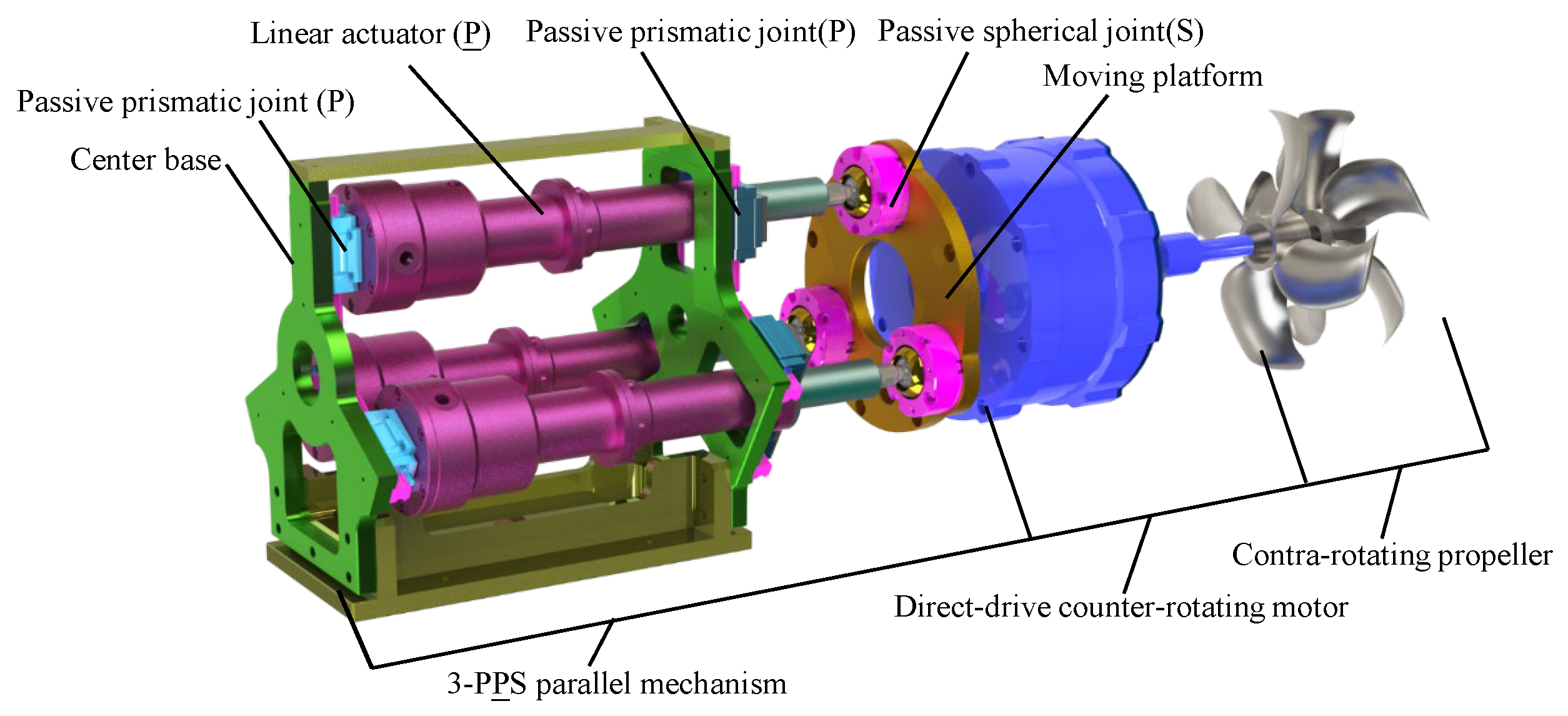
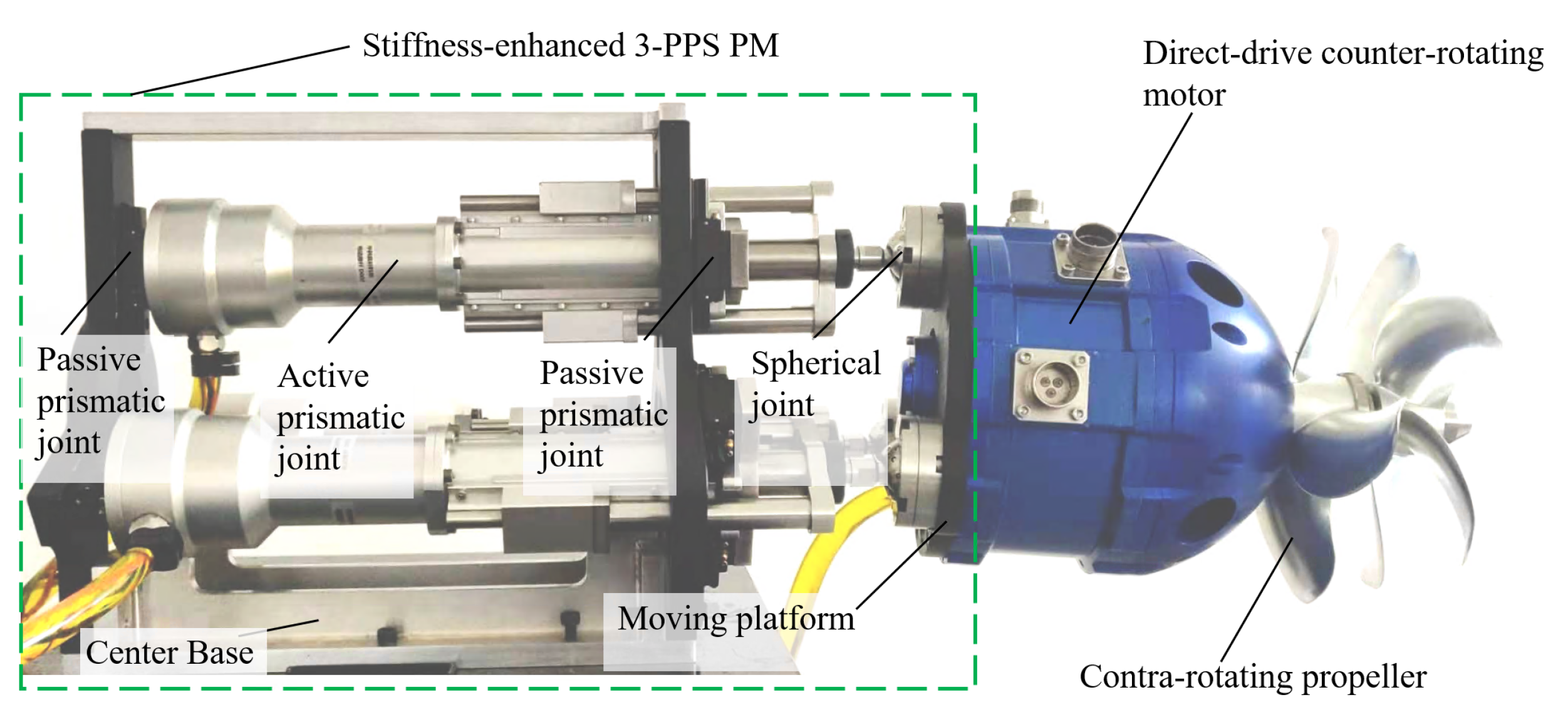
Compared with the traditional 3-PPS parallel mechanism, a center base with redundant passive prismatic joints is added in the new design, which significantly shorten the distance L t between the moving platform and the base without changing the kinematic characteristics. Furthermore, through adjusting the distance among A i 1 , A i 2 , and A i 3 ( i = 1 , 2 , 3 ) , the existing clearance of the passive prismatic joints can be reduced or even eliminated, thereby decreasing the vibration amplitude of the system. Therefore, the stiffness-enhanced 3-PPS parallel mechanism not only has higher stiffness and higher accuracy, but also maintains similar kinematic characteristics to the traditional 3-PPS parallel mechanism. Moreover, based on these advantages, a new underwater vectored thruster consisting of a stiffness-enhanced 3-PPS parallel mechanism, a direct-drive counter-rotating motor and counter-rotating propellers, is proposed, as shown in Figure 3. The design issue of the stiffness-enhanced 3-PPS parallel mechanism is studied in detail in this paper, especially workspace analysis under an arbitrary single actuator failure.

2.2. Displacement Analysis

In this section, the relationship between the active joint variables and the moving platform poses is derived by a coordinate transformation method considering two cases, i.e., all actuators are moveable, and one of the actuators becomes stuck.
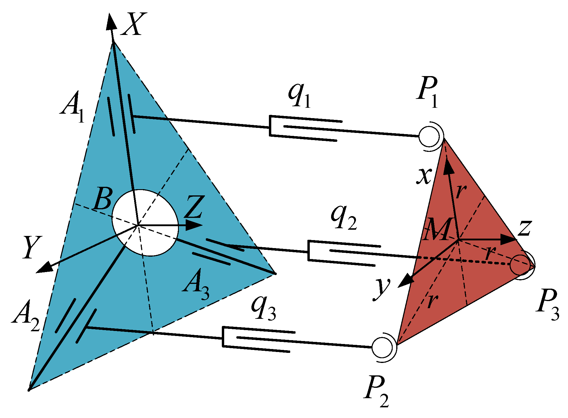
Referring to Figure 4, both the base frame B and the moving platform frame M are right-hand Cartesian coordinate frames. The base frame B is attached to the center of the base plate with its Z-axis perpendicular to the base plate and X-axis parallel to A 3 A 2 . The moving plaeform frame M is attached to the center of the circle determined by the centers of three spherical joints with its z-axis perpendicular to the moving platform and y-axis parallel to line vector P 3 P 2 . The home configuration is that the three axes of frame M are parallel to those of frame B each other and all active joints variables are equal to zero.

2.2.1. Inverse Displacement Analysis under Failure-Free Operation

As any orientation matrix R S O ( 3 ) can be always achieved by a rotation about a unit vector ω = ω x ω y ω z T R 3 × 1 with an angle θ 0 , 2 π , the orientation matrix R B M ( ω , θ ) of the frame M with respect to the frame B can be generated by Rodrigue’s formula [29]:
R B M ( ω , θ ) = e ω ^ θ = I 3 × 3 + ω ^ sin θ + ω ^ 2 ( 1 cos θ )
where ω ^ s o ( 3 ) is a skew-symmetric matrix concerning ω .
Define r as the circumcircle radius of the equilateral triangular P 1 P 2 P 3 attached to the moving platform. The local coordinates of points P i i = 1 , 2 , 3 with respect to the frame M , denoted by P i M i = 1 , 2 , 3 , are:
P i M = r cos φ i r sin φ i 0 T
where φ i = 2 π i 1 / 3 , i = 1 , 2 , 3 .
The coordinates of point P i with respect to the frame B are derived by a coordinate transformation method as:
P i B = R B M ( ω , θ ) P i M + M B
where M B = P x P y P z T denotes the position of the origin of the frame M with respect to the frame B .
The point P i with respect to frame B is obtained by expanding Equation (3) as:
P i B = P i x P i y P i z T = P x + r sin φ i ω x ω y v θ ω z sin θ + r ω x 2 cos φ i v θ P y + r ω x ω y cos φ i v θ + ω y 2 v θ sin φ i + ω z sin θ cos φ i + cos θ sin φ i P z r cos φ i ω x ω z v θ + ω y sin θ + r sin φ i ω x sin θ + ω y ω z v θ
where v θ = ( 1 cos θ ) .
Since the mechanical constraint of passive prismatic joints, point A i always moves in the plane constructed by B A i and the Z- axis . Thus, constraint equations are obtained as:
P i y = tan φ i P i x
The variables, ω z , P x , and P y , are solved from Equation (5) as:
ω z = 0 P x = r ω y 2 v θ ( r v θ ) / 2 P y = r ω x ω y v θ
Attributing to the above result ω z = 0 , R B M ( ω , θ ) can be characterized with three variables, i.e., ω x , ω y , and θ . In practical application scenarios, the direction of the thrust always coincides with the normal of the moving platform as is shown in Figure 5. The initial normal direction of the moving platform is defined with a unit vector u z = 0 0 1 T coinciding with the Z- axis . Once the orientation of the moving platform is changed, the normal of the moving platform becomes u z :
u z = R B M ( ω , θ ) u z = ω y sin θ ω x sin θ cos θ T
As a result of ω = 1 , u z can be always described in spherical coordinates as:
u z = cos α sin θ sin α sin θ cos θ T
where ω x = cos ( π / 2 + α ) , ω y = sin ( π / 2 + α ) .
α and θ are denoted as an azimuth angle and a tilt angle [32], respectively. The azimuth angle α varies from 0 to 2 π , and the tilt angle θ is always less than the maximum swing angle ϕ max [ 0 , π / 2 ) of a spherical joints due to the existence of mechanical constraints.
Benefiting from the fact that all limbs are perpendicular to the base, the real-time swing angle of all spherical joints is always the same, which is also equal to the tilt angle. Denote ϕ as the swing angle of the spherical joint, which can be determined from the following formula:
ϕ = arccos u z . u z u z u z
Owing to the displacement q i ( i = 1 , 2 , 3 ) , of the ith limb is equal to the Z coordinate of P i B , its solution can be readily obtained through substituting Equations (2) and (6) into Equation (4) and extracting the Z coordinate of P i B . The inverse displacement solution under failure-free operation is simplified as:
q 1 = P z r cos α sin θ q 2 = P z + 1 2 r cos α sin θ 3 2 r sin α sin θ q 3 = P z + 1 2 r cos α sin θ + 3 2 r sin α sin θ
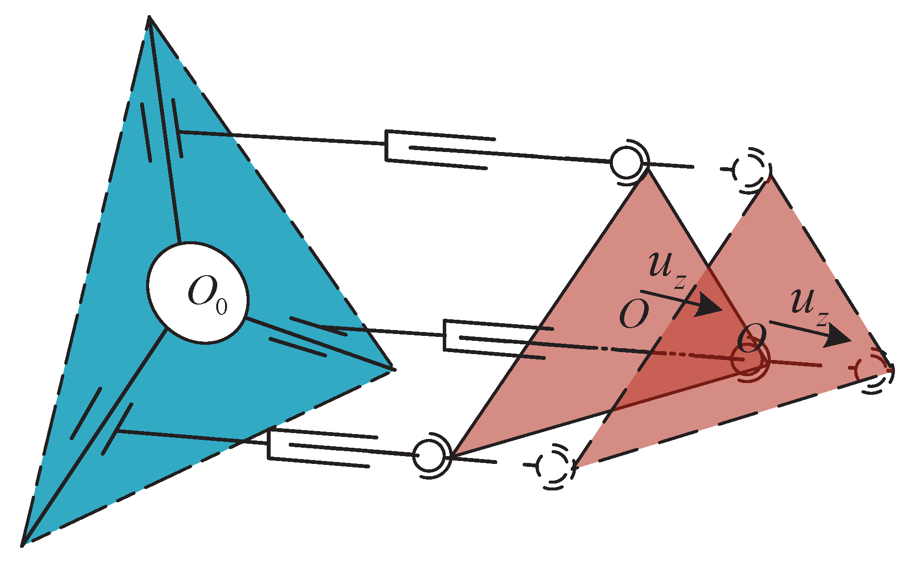
However, the parallel mechanism works as a thrust-vectoring mechanism which only needs two-rotational DOFs. If only the orientation, α and θ , is given, but P z is not specified, q i cannot be determined uniquely because the moving platform may reach countless positions while maintaining the same orientation [33], as shown in Figure 6. In Section 3, the workspace analysis shows that the maximum workspace of the parallel mechanism can be obtained when the Z coordinate of M B always locates in the middle of the stroke of limbs. Therefore, this problem can be addressed by presetting a default value P z d of P z .
P z d = q i m a x q i m i n 2 + q i m i n
where q i m i n , q i m a x are the minimum and the maximum of the q i , respectively.

2.2.2. Inverse Displacement Analysis under a Single Actuator Failure

When one of the actuators becomes stuck, the length of the corresponding limb stays constant, and this length can be obtained by reading the data of the displacement coder. For instance, when the limb q 1 is in failure, q 1 is equal to q 1 c .
q 1 q 1 c
According to Equation (10), P z becomes a parasitic motion that is:
P z = q 1 c + r cos α sin θ
Substituting Equations (12) and (13) into Equation (10), the inverse displacement solution is obtained under the actuation failure of limb q 1 , simplified to:
q 1 = q 1 c q 2 = q 1 c 3 2 r sin α sin θ + 3 2 r cos α sin θ q 3 = q 1 c + 3 2 r sin α sin θ + 3 2 r cos α sin θ
Similarly, when limb q 2 is in failure, the corresponding inverse displacement solution is:
q 1 = q 2 c + 3 2 r sin α sin θ 3 2 r cos α sin θ q 2 = q 2 c q 3 = q 2 c + 3 r sin α sin θ
The inverse displacement solution under the failure of limb q 3 is:
q 1 = q 3 c 3 2 r sin α sin θ 3 2 r cos α sin θ q 2 = q 3 c 3 r sin α sin θ q 3 = q 3 c
According to Equations (10) and (14)–(16), the closed-form inverse displacement solution can be expressed in a unified linear representation:
q 1 q 2 q 3 = J p ( J q i + I 3 × 3 ) u x u y P z = J u x u y P z
where J p = r 0 1 r / 2 3 r / 2 1 r / 2 3 r / 2 1 , S i = 1 i = 1 , 2 , 3 0 o t h e r w i s e , P z = P z d S i = 0 C q i S i = 1 , J q i = 0 3 × 1 0 3 × 1 S i P i M T 3 × 3 T . S i is a fault indicator. S i = 1 represents the existence of fault, while S i = 0 implies no failure. i implies that i t h limb is in failure. u x = cos α sin θ , u y = sin α sin θ .
According to the research [29], both inverse and forward displacement solutions exist uniquely in the task space of this work, i.e., α 0 , 2 π and θ 0 , π / 2 . Thus, through Equation (17), the forward displacement solution is readily derived as:
u x u y P z = J 1 q 1 q 2 q 3
According to Equation (17), the tilt angle θ can be obtained as:
θ = u x 2 + u y 2
  • Define an intermediate variable α 1 to determine the value of azimuth angle α . When θ 0 , α 1 = a t a n 2 ( u y / sin θ , u x / sin θ ) . The azimuth angle α can be given by:
α = α 1 α 1 0 α 1 + 2 π α 1 < 0
  • When θ = 0 , α 1 = a r b i t r a r y . In this case, the frame M is parallel to the frame B , and the moving platform is in instantaneous translation. Thus, the azimuth angle can be set as α = 0 .

3. Workspace Analysis

3.1. Workspace Analysis under Failure-Free Operation

To calculate the volume of workspace, an equi-volumetric partition method [34] is employed. Thereafter, for the sake of the completeness, the equi-volumetric partition scheme is briefly introduced, as follows:
Step 1:
Partitioning circular disc into concentric bands
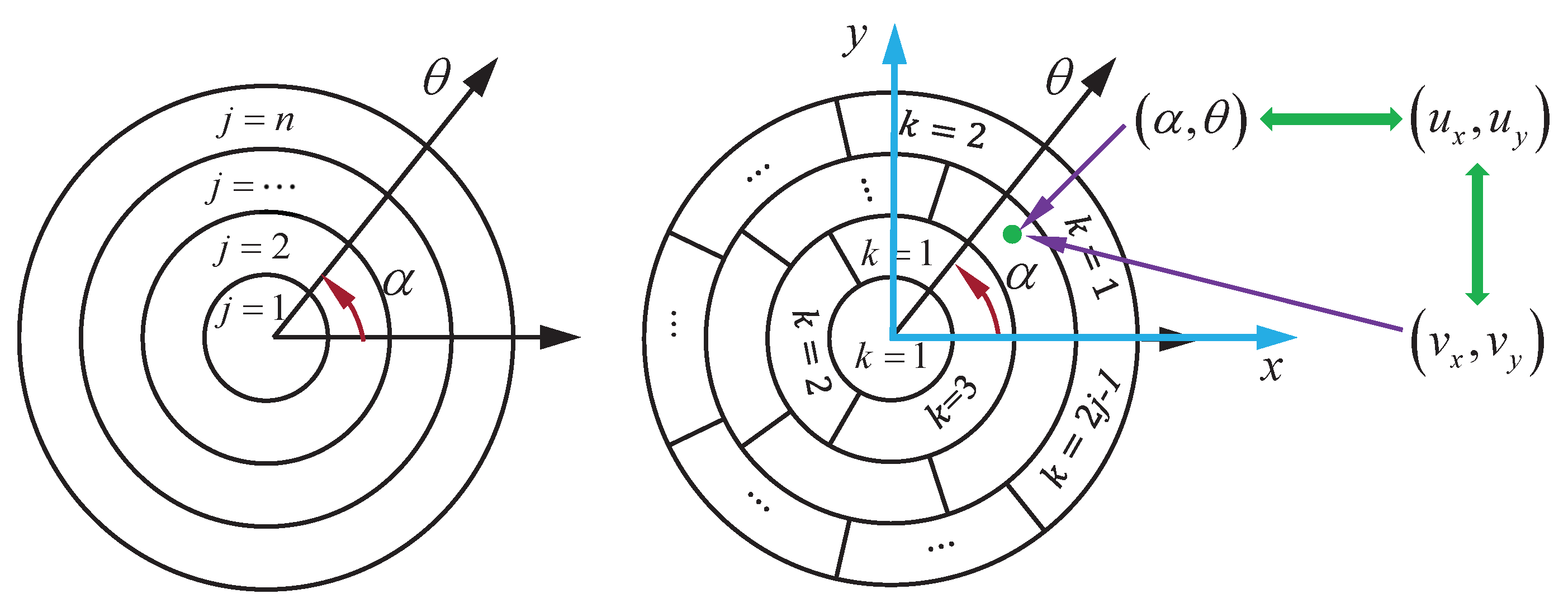
Divide the circular disc into n circular band with the same thickness ( δ θ = π / ( 2 n ) ) along radial direction, as shown in Figure 7. The first one in the center, i.e., the center element is a small circular disc of radius π / ( 2 n ) . Label the circular bands from 1 to n starting from the center element.
Step 2:
Partitioning circular band into elements
The center element in the circular disc is considered to be the basic element and no partition is needed. Furthermore, its volume, i.e., V t = π 3 / ( 4 n 2 ) , is defined as the unit volume for the equi-volumetric partition scheme. The jth circular band is partitioned into 2 j 1 elements with identical volume of V t . For the jth circular band, label the partitioned 2 j 1 equi-volumetric elements using index k such that k = 1 , . . . , 2 j 1 , starting from x axis counterclockwise. In this way, the circular disc can be equi-volumetrically divided into j = 1 n ( 2 j 1 ) = n 2 elements. Altogether, the entire disc can be partitioned into n 2 elements with identical volume of V t .
The coordinate α , θ is mapped to v x , v y one by one except for θ = 0 , while α = a r b i t r a r y , θ = 0 is mapped to v x = 0 , v y = 0 which is a point. The relationship between α , θ , u x , u y and v x , v y can be derived from Equation (18) as:
α , θ θ 0 a r b i t r a r y , 0 o t h e r w i s e u x , u y v x , v y
where v x = θ cos α and v y = θ sin α .
The dual index j , k can be readily computed, i.e., j = c e i l θ δ θ , k = c e i l α δ α , δ α = 2 π / ( 2 j 1 ) . c e i l ( . ) rounds element to the nearest integer greater than or equal to that element, and its specific usage can be found in MATLAB software. The workspace of interest for a set of rotations S S O ( 3 ) can be numerically computed as:
S d V R j = 1 n k = 1 2 j 1 s i g [ j , k ] V t , s i g [ j , k ] = 1 , j = 1 , , n ; k = 1 , , 2 j 1 0 , o t h e r w i s e
where S is the field of integration.
To analyze the workspace boundary, both the maximum swing angle ϕ m a x and the desired maximum tilt angle are set as π / 6 . According to Equation (22), the desired workspace can be obtained and is plotted in Figure 8. The volume V d of the desired workspace is:
V d = π θ d 2 .
In desired situation (i.e., P z P z d ), the minimum length q N m i n and the maximum length q N m a x of every limb are obtained by solving the Equation (10).
q N m i n = max q i = P z d r sin θ d q N m a x = max q i = P z d + r sin θ d
Moreover, a basic stroke L b of all actuators is determined by meeting the requirements of failure-free operation as:
L b = q N m a x q N m i n = 2 r sin θ d
For the parallel mechanism, V d , L b , q N m i n and q N m a x are the foundation to construct a fault-tolerant index and to determine the minimum stroke of limbs.

3.2. Workspace Analysis under a Single Actuator Failure

To analyze the workspace distribution under actuation failure, the FTW and the MIW are separately defined, i.e., the FTW is the reachable workspace after an arbitrary locked-joint failure, and the MIW is a circular region centered on the origin of polar coordinates and inscribed in the FTW. Moreover, a normalization method is employed to nondimensionalize the fault position q i F of limb q i , so as to eliminate the interference of the radius of the moving platform and reduces the difficulty of analysis.
λ q i = q i F q N m i n / q N m a x q N m i n = m L b / n / L b = m / n
where λ q i is the proportional position relative to the basic stroke of the limb L b . q i F is the failure position, n m 0 , m , n = 1 , 2 , 3 ,
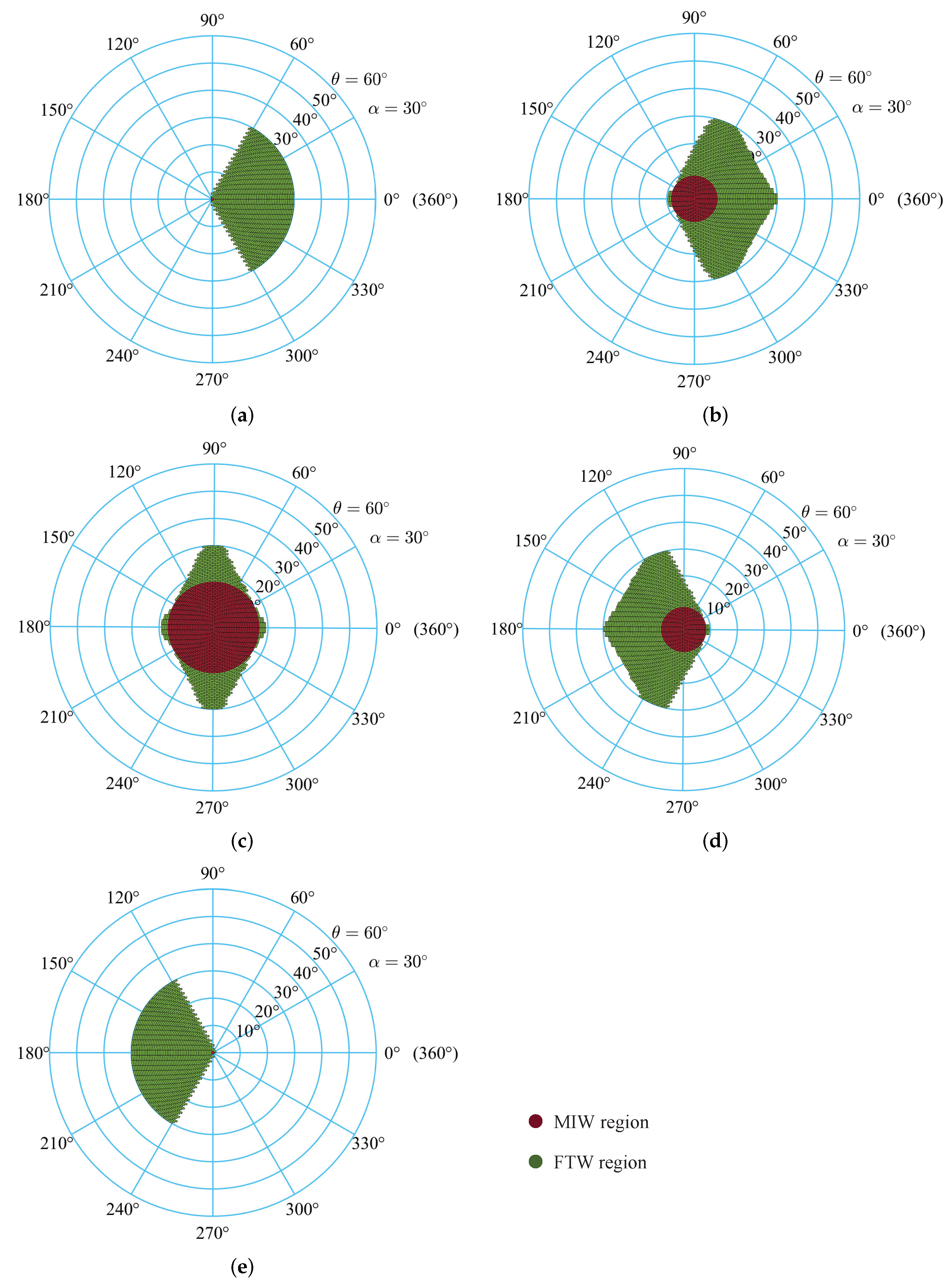
There are five typical fault situations of limb q 1 demonstrated in Figure 9. In the figure, the FTW is colored green, and the MIW is shown in red. The MIW distribution is a collection of all MIW under different failure positions, and it is denoted as {MIW 1 , MIW 2 , ⋯, MIW n }, ( n = 1 , 2 , 3 , . . . ). In addition, Figure 9a shows that the FTW under failure position λ q 1 = 0 cannot reach the left side of the desired workspace, while Figure 9e demonstrates that the FTW under failure position λ q 1 = 1 cannot obtain the right side of the desired workspace. In particular, the volume of MIW n is readily obtained as:
Benefiting from the symmetric structure of the parallel mechanism [35], the FTW under the actuation failure of limb q 2 is obtained by rotating the FTW under the actuation failure of limb q 1 by 2 π / 3 counterclockwise direction around the origin of polar coordinates, and the FTW under the actuation failure of limb q 3 is obtained by rotating the FTW under the actuation failure of limb q 1 by 2 π / 3 counterclockwise direction around the origin of polar coordinates.
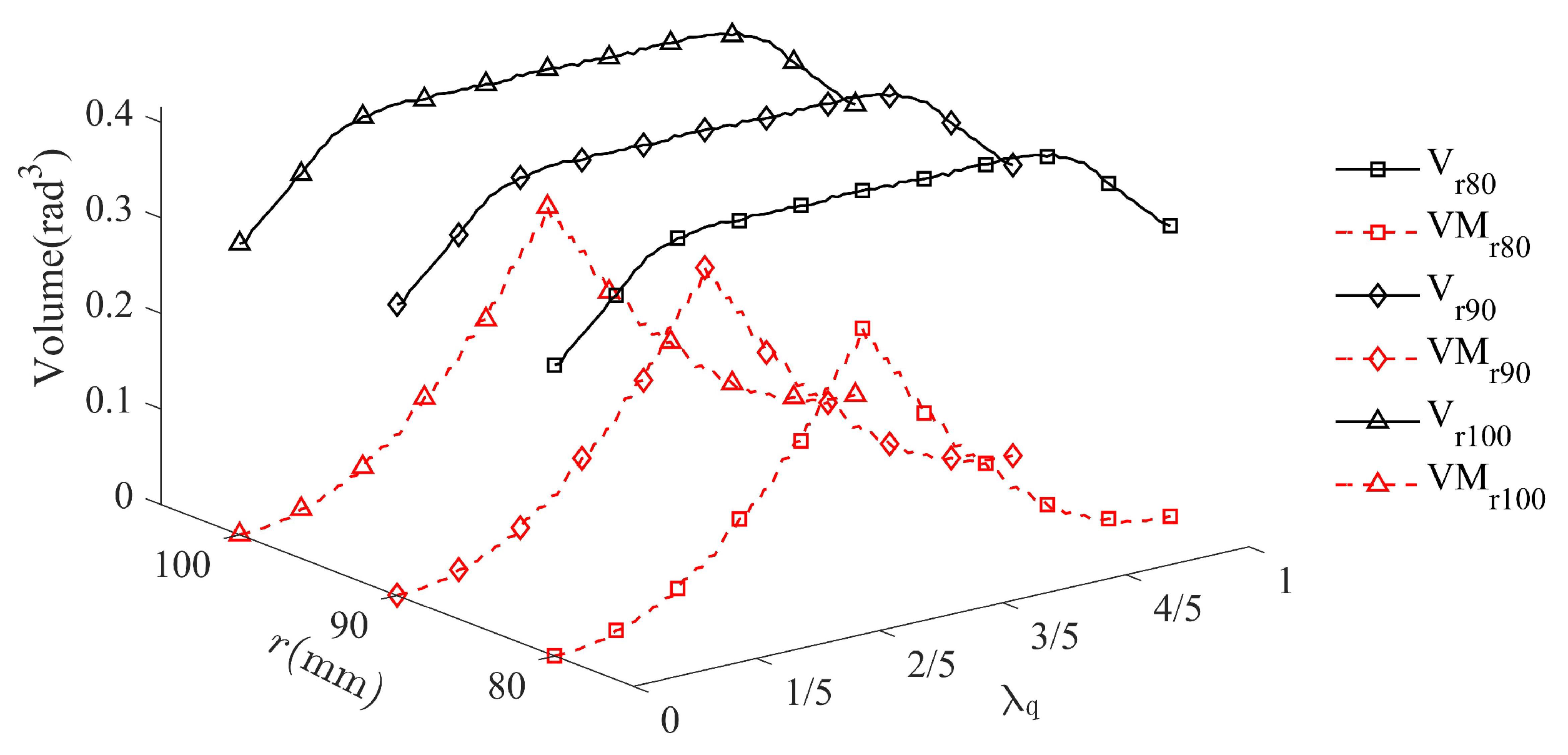
As shown in Figure 10, the volume of the MIW reaches the minimum at the start or destination position of the basic stroke of limbs (i.e., λ q 1 = 0 and λ q 1 = 1 ), while the volume of the FTW remains roughly the same no matter where the failure occurs. Figure 10 demonstrates that the change of FTW and MIW is independent of the radius of the moving platform r. Its volume curve is significant to increase or decrease at different failure position, which is useful for optimization design owing to its convexity.
V n = π θ n 2 , n = 1 , 2 , 3 , . . .
where θ n is the radius of the MIW n .
These results indicate that it is not an effective way to evaluate the fault tolerance of the parallel mechanism by its workspace volume but ignoring its distribution in space. Moreover, the FTW have an irregular boundary, which complicates the global measures of fault tolerance for the parallel mechanism. Nevertheless, in the applications of thrust-vectoring device, the omnidirectional reachability of the parallel mechanism (i.e., the azimuth angle of the parallel mechanism varies from 0 to 2 π , and the tilt angle of the parallel mechanism is always expected to be non-zero.) is an essential performance. To characterize the performace in a straightforward form, the MIW is employed owing to it has a clear physic meaning. Therefore, the MIW can replace the FTW as a global measure of fault tolerance in terms of the parallel mechanism applied in the thrust-vectoring device.

3.3. Fault-Tolerant Criterion and Design Based on the Workspace

Based on the results of workspace analysis, a new fault-tolerant index FTI is proposed first. In applications, the worst situations of the parallel mechanism after a single actuator failure has to be considered in the design stage as the failure position is unknown in advance. In other words, the minimum volume of the MIW should be the most consideration for evaluating the fault tolerance of the parallel mechanism. Therefore, a fault-tolerant index is defined as the ratio of the minimum of V 1 , V 2 , , V n , n = 1 , 2 , 3 , . . . to the desired workspace V d :
F T I = min V 1 , V 2 , , V n V d
Owing to the MIW volume usually does not exceeds the desired worksapce volume, the value range of FTI can be expressed by:
0 F T I 1
The FTI characterizes the divergence between the MIW and the desired workspace. When the FTI is close to 1, it means that the same desired workspace and the same omnidirectional reachability can be obtained as before in the worst situation. When the FTI is 0, it implies that the omnidirectional reachability is vanished in the worst situation.
To design a parallel mechanism with desired FTI, an effective way is to modify the MIW at q i c = q N m i n and q i c = q N m a x to the desired reserve MIW. For instance, when q 1 c = q N m i n , Equation (14) can be converted to:
q 1 q N m i n = 0 q 2 q N m i n = 3 r sin θ f 1 1 2 sin α + 3 2 cos α q 3 q N m i n = 3 r sin θ f 1 1 2 sin α + 3 2 cos α
In this situation, the MIW radius is θ f 1 0 , π / 2 . Therefore, the lower limit of the displacement q i m i n must satisfy:
L l = q N m i n q i m i n 3 r sin θ f 1
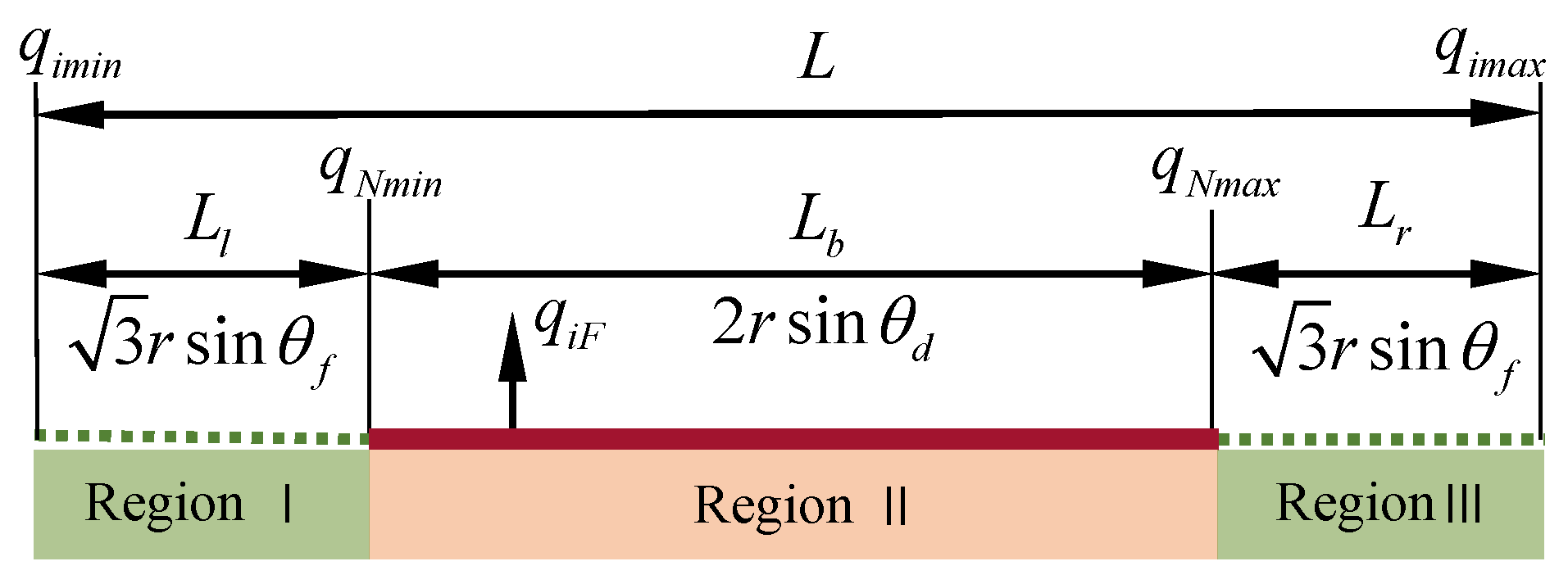
where L l denotes the stroke of the non-single actuator failure region on the left, as shown in Figure 11.
Similarly, when q 1 c = q N m a x , Equation (14) can be converted to:
q 1 q N m a x = 0 q 2 q N m a x = 3 r sin θ f 2 1 2 sin α + 3 2 cos α q 3 q N m a x = 3 r sin θ f 2 1 2 sin α + 3 2 cos α
In this situation, the MIW radius is θ f 2 0 , π / 2 . Therefore, the upper limit of the displacement q i m i n must satisfy:
L r = q i m a x q N m a x 3 r sin θ f 2
where L r denotes the stroke of the non-single actuator failure region on the right, as shown in Figure 11.
To maintain sufficient stiffness of the parallel mechanism, the stroke L should be as small as possible. Meanwhile, in order to keep the symmetric characteristics in fault tolerance design, θ f 1 and θ f 2 should be equal to each other, and they are denoted as θ f . Furthermore, combining Equations (23), (25), (27) and (28), the FTI is derived as θ f 2 / θ d 2 . The minimum stroke L of all limbs can be determined by:
L = L b + min L l + min L r = 2 r sin θ d + 3 sin η θ d
where η is the root mean square of F T I = , i.e., η = F T I = θ f / θ d .
According to Equation (34), the ratio of the minimum stroke L to the basic stroke L b is the Curve C s in Figure 12. It means that the optimal solution L can be determined by L b under given an F T I . For instance, 0.6 , 2.176 means that L = 2.176 L b when F T I = 0.6 .

4. Prototype Development and Experimental Validation

4.1. Prototype Development

To design a 2-DOF thrust-vectoring device for an underwater vectored thruster, two main design requirements need to be satisfied in failure-free operation, i.e., π / 9 for the maximum tilt angle about the vertical plane and FTI for the fault tolerance of the parallel mechanism. The main kinematic design parameters to be determined are the circumcircle radius of the equilateral triangular P 1 P 2 P 3 and the stroke of the active prismatic joints. Please note that the circumcircle radius of the equilateral triangular P 1 P 2 P 3 is determined by the connector of the direct-drive counter-rotating motor. According to the inverse displacement analysis formulated in Equation (17) and the relationship among the circumcircle radius of the equilateral triangular P 1 P 2 P 3 , fault tolerance and the stroke of limbs, the FTI of the parallel mechanism is eventually determined as 0.2703 so that the strokes of all active prismatic joints is 96 mm.
Based on the kinematic design parameters proposed in this work, a prototype of the stiffness-enhanced 3-PPS parallel mechanism is designed and fabricated, which consists of a center base, three identical P P ̲ S limbs are placed 120 apart, as shown in Figure 13. Specifically, the first prismatic joints in each limb consists of three passive prismatic joints parallel to each other, which shortens the distance between the base and the moving platform, so as to improve the stiffness of the parallel mechanism. The second prismatic joint in each limb is selected as the active joint which is placed horizontally. Three passive spherical joints are commercially available, whose permissible swing angles are ± 30 . In this specific design, the main technical specifications of the stiffness-enhanced 3-PPS parallel mechanism are determined and listed in Table 1.

4.2. Experiments Method and Validation

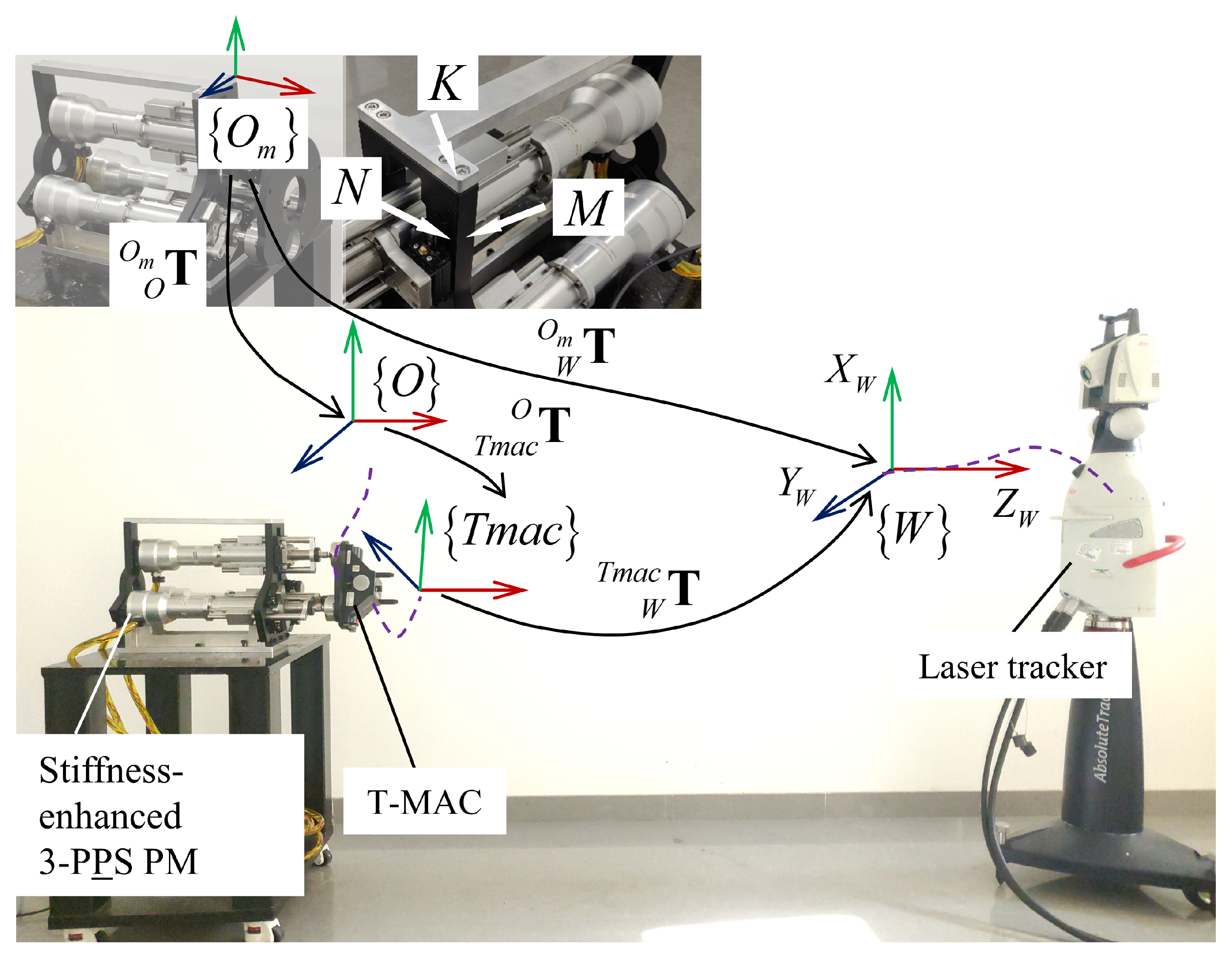
The orientation of the moving platform was measured using Leica emScon Absolute Tracker AT901-MRwith a T-MAC 6 DOFs sensor, which has a measurement accuracy of 30 µm. Its supporting data acquisition software is SpatialAnalyzer. The layout of the measurement system is shown in Figure 14. Thereby, the measurement data can be obtained from the laser tracker as following steps:
Step 1:
Building measurement frame O m
The measurement frame is determined by three planes K, M, and N. Their intersection is the origin of the frame O m . The setting of the three axes are shown in Figure 14.
Step 2:
Setting initial orientation
The initial state of the moving platform is adjusted by using a level to ensure that the initial orientation matrix O m O R 1 is a 3 × 3 identity matrix.
Step 3:
Processing measurement data
Since the T-MAC is fixed on the moving platform by screws, the local frame T m a c is attached to the T-MAC. Thereby, O T m a c R is a constant rotation transformation, and O m T m a c R can be read from the software SpatialAnalyzer and satifies:
O m T m a c R k = O m O R k O T m a c R
where the subscript k is k t h data.
Thus, the actual rotation tranformation O m O R k is equal to the relative rotation transformation R k 1 between the k t h data and initial posture for the moving platform.
O m O R k = R k 1 = O m T m a c R k O T m a c R 1 1 = c 11 c 12 c 13 c 21 c 22 c 23 c 31 c 32 c 33
where c m n ( m , n = 1 , 2 , 3 ) is the element in m t h row and n t h column of the orientation matrix.
Given the displacements of limbs, the theoretical azimuth angle α n and the theoretical tilt angle θ n can be derived from Equations (18)–(20). According to Ref. [36], the actual azimuth angle α a and the actual tilt angle θ a can be derived from the O m O R k as follows:
  • Define an intermediate variable α 2 to determine the value of azimuth angle α a , When θ a = a t a n 2 c 31 2 + c 32 2 , c 33 0 , α 2 = a t a n 2 c 23 / s θ , c 13 / s θ . The actual azimuth angle α a can be given by:
α a = α 2 α 2 0 α 2 + 2 π α 2 < 0
  • When θ a = 0 , α 2 = a r b i t r a r y . Similar to Equations (19) and (20), the azimuth angle can be set as α a = 0 .
Step 4:
Measuring the orientation of the T-MAC
The point cloud data of the desired workspace is obtained from the sensor. A few hundred measurements are collected by changing the displacements of every limb. These displacements can be derived from Equation (17) by assigning the coordinates α , θ , where the azimuth angle α changes from 0 to 2 π in steps of π / 18 , and the tilt angle θ ranges from 0 to π / 9 advance in steps of π / 36 . In terms of one actuator failure, the input variable that is the displacement q i n of the limb q i : q i n = q i q i min , is known. Similar to the previous analysis, the actuator failure of limb q 1 is taken as an example, which is implemented as in Table 2. The total number of the combination q 1 n , q 2 n , q 3 n is 121.
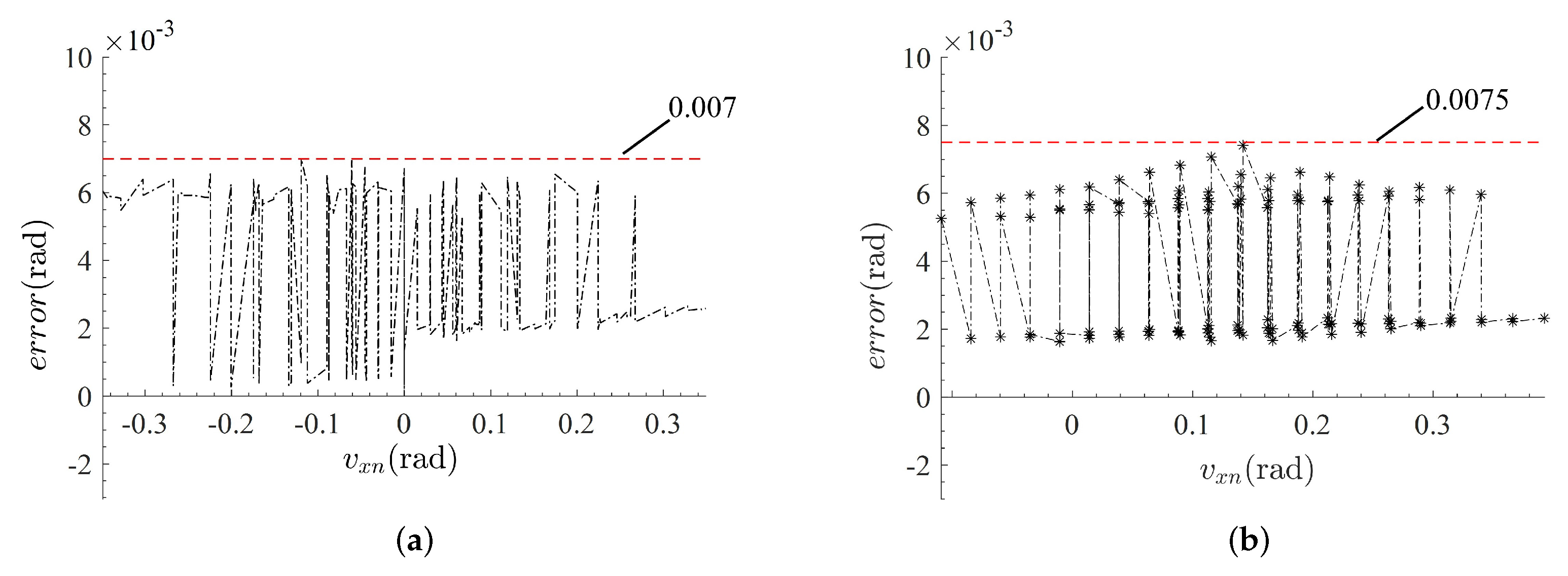
According to Equation (21), the experimental data ( α a , θ a ) and the nominal data ( α n , θ n ) are converted to ( v x a , v y a ) and ( v x n , v y n ), respectively. The experimental data ( v x a , v y a ) and the corresponding nominal data ( v x n , v y n ) are plotted in the polar coordinates, as shown in Figure 15. In addition, the error between the experiment and the nominal situation can be evaluated as:
e r r o r = ( v x a 2 v x n 2 ) 2 + ( v y a 2 v y n 2 ) 2
According to the Equation (38), the errors are plotted in Figure 16. Figure 16a shows that the maximum error between the experiment and the nominal situation under failure-free operation is less than 0.007 (rad). Figure 16b indicate that the maximum error between the experiment and the nominal situation under limb q 1 failure is less than 0.007 (rad). They mean that the prototype has extremely design stiffness, and the workspace analysis of the parallel mechanism can be validated under failure-free operation and a single actuator failure.

5. Conclusions

In this paper, a stiffness-enhanced 3-degree-of-freedom 3-PPS parallel mechanism employing additional linear guides for the passive prismatic joints is proposed, which is used as the thrust-vectoring device of a fault-tolerant underwater vectored thruster. Compared with the traditional 3-PPS parallel mechanism, the stiffness-enhanced 3-PPS parallel mechanism has a shorter distance between the moving platform and the base, so that its stiffness and accuracy are improved.
In addition, a fault-tolerant index (FTI) is presented to evaluate the fault tolerance of the parallel mechanism, which is defined as the ratio of the minimum volume in the MIW distribution to the desired workspace. The FTI not only quantifies the fault tolerance of the parallel mechanism, but also characterizes the worst omnidirectional reachability for the parallel mechanisms. An analytic relationship among the circumcircle radius of the equilateral triangular P 1 P 2 P 3 , fault tolerance and the minimum stroke of limbs is formulated. According to the formulation, the minimum stroke of all limbs for the 3-PPS parallel mechanism is readily determined, without complex numerical algorithms.
Furthermore, considering the actuation failure, the displacement analysis is addressed through a coordinate transformation method, and closed-form solutions are obtained in a unified linear representation for both forward and inverse displacement. The unified linear representation including a fault indicator can reduce the complexity of control procedure and increase the computational efficiency.
Based on the displacement analysis, the distribution of the fault-tolerant workspace (FTW) and the maximum inscribed workspace (MIW) are investigated through an equi-volumetric partition method to find the minimum volume of the MIW distribution. In comparison, the MIW has a regular boundary and clear physical meaning. Thus, it is very helpful in trajectory planning.
Finally, a prototype is fabricated. The workspace experiment results show that the experimental errors are less than 0.0075 (rad) with respect to the simulation values, which verifies the effectiveness of the design analysis. Based on this work, future work will focus on the trajectory planning and motion control for the stiffness-enhanced 3-PPS parallel mechanism.

Author Contributions

Conceptualization, G.Y.; Methodology, D.J.; Software, D.J.; Validation, D.J.; Formal Analysis, D.J.; Investigation, D.J.; Resources, G.Y., T.Z. and H.L.; Data Curation, D.J.; Writing—Original Draft Preparation, D.J.; Writing—Review & Editing, T.Z., G.Y. and Z.F.; Visualization, D.J.; Supervision, Y.T., C.Z. and H.Y.; Project Administration, T.Z.; Funding Acquisition, G.Y., T.Z., Z.F. and H.L. All authors have read and agreed to the published version of the manuscript.

Funding

This research was funded by the National Key Research and Development Program of China (No. 2018YFB1308900); the National Nature Science Foundation (No. U1909215, No. 92048201); the Strategic Priority Research Program of the Chinese Academy of Sciences (No. XDA22000000); the Ningbo Key Project of Scientific and Technological Innovation 2025 (No. 2018B10069, No. 2018B10058).

Institutional Review Board Statement

Not applicable.

Informed Consent Statement

Not applicable.

Data Availability Statement

Data can be available from [email protected].

Acknowledgments

The authors are very thankful to the support of the National Key Research and Develoment Program of China (2018YFB1308900); the National Nature Science Foundation (U1909215, 92048201); the Strategic Priority Research Program of the Chinese Academy of Sciences (XDA22000000); the Ningbo Key Project of Scientific and Technological Innovation 2025 (2018B10069, 2018B10058).

Conflicts of Interest

The authors declare no conflict of interest.

References

  1. Barker, L.D.L.; Jakuba, M.; Bowen, A.D.; German, C.R.; Maksym, T.; Mayer, L.; Boetius, A.; Dutrieux, P.; Whitcomb, L.L. Scientific challenges and present capabilities in underwater robotic vehicle design and navigation for oceanographic exploration under-ice. Remote Sens. 2020, 12, 2588. [Google Scholar] [CrossRef]
  2. Paull, L.; Saeedi, S.; Seto, M.; Li, H. AUV navigation and localization: A review. IEEE J. Ocean. Eng. 2014, 39, 131–149. [Google Scholar] [CrossRef]
  3. Cardenas, P.; de Barros, E.A. Estimation of AUV Hydrodynamic Coefficients Using Analytical and System Identification Approaches. IEEE J. Ocean. Eng. 2020, 45, 1157–1176. [Google Scholar] [CrossRef]
  4. Panda, J.P.; Mitra, A.; Warrior, H.V. A review on the hydrodynamic characteristics of autonomous underwater vehicles. Proc. Inst. Mech. Eng. Part M J. Eng. Marit. Environ. 2021, 235, 15–29. [Google Scholar] [CrossRef]
  5. Xiu, Y.; Geng, L.; Hu, Z.; Wang, X. Research on underwater fluidic thrust vectoring method based on active flow control technique. In Proceedings of the 2020 5th International Conference on Mechanical, Control and Computer Engineering (ICMCCE), Harbin, China, 25–27 December 2020; pp. 582–587. [Google Scholar]
  6. Ba, X.; Luo, X.; Shi, Z.; Zhu, Y. A vectored water jet propulsion method for autonomous underwater vehicles. Ocean Eng. 2013, 74, 133–140. [Google Scholar]
  7. Chao, S.; Guan, G.; Hong, G.-S. Design of a finless torpedo shaped micro AUV with high maneuverability. In Proceedings of the OCEANS 2017—Anchorage, Anchorage, AK, USA, 18–22 September 2017; pp. 1–6. [Google Scholar]
  8. Saltaren, R.; Aracil, R.; Alvarez, C.; Yime, E.; Sabater, J.M. Field and service applications—Exploring deep sea by teleoperated robot—An Underwater Parallel Robot with High Navigation Capabilities. IEEE Robot. Autom. Mag. 2007, 14, 65–75. [Google Scholar] [CrossRef]
  9. Jiao, W.; Cheng, L.; Zhang, D.; Zhang, B.; Su, Y. Investigation of Key Parameters for Hydraulic Optimization of an Inlet Duct Based on a Whole Waterjet Propulsion Pump System. Trans. FAMENA 2021, 45, 145–162. [Google Scholar] [CrossRef]
  10. Gu, S.; Guo, S.; Zheng, L. A highly stable and efficient spherical underwater robot with hybrid propulsion devices. Auton. Robot. 2020, 44, 759–771. [Google Scholar] [CrossRef]
  11. Wang, R.; Guo, X.; Zhong, S. An Underwater Vector Propulsion Device Based on the RS+2PRS Parallel Mechanism and Its Attitude Control Algorithm. Appl. Sci. 2019, 9, 5210. [Google Scholar] [CrossRef] [Green Version]
  12. Barack, C.; Condo, A.; Fathauer, K.; Humanchuk, J.; Justice, B.; Limes, N.; Miller, B.; Parekh, P.; Tian, A.; Sender, T.; et al. The Ohio State University Underwater Robotics Puddles AUV Design and Implementation. 2019, p. 7. Available online: https://robonation.org/app/uploads/sites/4/2019/10/OSU_RS19_TDR.pdf (accessed on 20 December 2021).
  13. Ali, M.A. Spherically Designed Autonomous Underwater Vehicle (AUV). 2020. Available online: https://www.researchgate.net/publication/351713015 (accessed on 20 December 2021).
  14. Liu, T.; Hu, Y.; Xu, H.; Zhang, Z.; Li, H. Investigation of the vectored thruster AUVs based on 3SPS-S parallel manipulator. Appl. Ocean Res. 2019, 85, 151–161. [Google Scholar] [CrossRef]
  15. Cavallo, E.; Michelini, R.C.; Filaretov, V.F. Conceptual design of an AUV equipped with a three degrees of freedom vectored thruster. J. Intell. Robot. Syst. 2004, 39, 365–391. [Google Scholar] [CrossRef]
  16. Zhu, D.; Wang, L.; Hu, Z.; Yang, S.X. A Grasshopper Optimization-based fault-tolerant control algorithm for a human occupied submarine with the multi-thruster system. Ocean Eng. 2021, 242, 110101. [Google Scholar] [CrossRef]
  17. Jiang, D.; Zheng, T.; Tian, Y.; Li, H.; Zhang, C.; Yang, G. Dynamics Analysis of a Novel Underwater Vectored Thruster Based on 3-PPS Parallel Mechanism. In Proceedings of the 2021 3rd International Symposium on Robotics & Intelligent Manufacturing Technology (ISRIMT 2021), Changzhou, China, 24–26 September 2021; pp. 17–23. [Google Scholar]
  18. Li, X.; Zhu, D.; Mei, Z.; Jiang, D. Kinematic analysis of 3-RPS parallel mechanism. In Proceedings of the 2017 2nd International Conference on Robotics and Automation Engineering (ICRAE), Shanghai, China, 29–31 December 2017; pp. 183–187. [Google Scholar]
  19. McInroy, J.E.; O’Brien, J.F.; Neat, G.W. Precise, fault-tolerant pointing using a Stewart platform. IEEE ASME Trans. Mechatron. 1999, 4, 91–95. [Google Scholar] [CrossRef]
  20. Hassan, M.; Notash, L. Design modification of parallel manipulators for optimum fault tolerance to joint jam. Mech. Mach. Theory 2005, 40, 559–577. [Google Scholar] [CrossRef]
  21. Schreiber, L.-T.; Gosselin, C. Kinematically redundant planar parallel mechanisms: Kinematics, workspace and trajectory planning. Mech. Mach. Theory 2018, 119, 91–105. [Google Scholar] [CrossRef]
  22. Hassan, M.; Notash, L. Optimizing fault tolerance to joint jam in the design of parallel robot manipulators. Mech. Mach. Theory 2007, 42, 1401–1417. [Google Scholar] [CrossRef]
  23. Yi, Y.; McInroy, J.E.; Chen, Y. Fault tolerance of parallel manipulators using task space and kinematic redundancy. IEEE Trans. Robot. 2006, 22, 1017–1021. [Google Scholar]
  24. Cha, S.-H.; Lasky, T.A.; Velinsky, S.A. Determination of the kinematically redundant active prismatic joint variable ranges of a planar parallel mechanism for singularity-free trajectories. Mech. Mach. Theory 2009, 44, 1032–1044. [Google Scholar] [CrossRef]
  25. Pazmiño, R.S.; Cena, C.E.G.; Arocha, C.A.; Santonja, R.A. Experiences and results from designing and developing a 6 DoF underwater parallel robot. Robot. Auton. Syst. 2011, 59, 101–112. [Google Scholar] [CrossRef]
  26. Liu, T.; Hu, Y.; Xu, H.; Wang, Q.; Du, W. A novel vectored thruster based on 3-RPS parallel manipulator for autonomous underwater vehicles. Mech. Mach. Theory 2019, 133, 646–672. [Google Scholar] [CrossRef]
  27. Bader, A.M.; Maciejewski, A.A. Maximizing the failure-tolerant workspace area for planar redundant robots. Mech. Mach. Theory 2020, 143, 103635. [Google Scholar] [CrossRef]
  28. Liu, X.-J.; Wang, J.; Oh, K.-K.; Kim, J. A New Approach to the Design of a DELTA Robot with a Desired Workspace. J. Intell. Robot. Syst. 2004, 39, 209–225. [Google Scholar] [CrossRef]
  29. Yang, G.; Zhu, R.; Fang, Z.; Chen, C.; Zhang, C. Kinematic design of a 2R1T robotic end-effector with flexure joints. IEEE Access 2020, 8, 57204–57213. [Google Scholar] [CrossRef]
  30. Zhang, D.; Wei, B. Study on the Kinematic Performances and Optimization for Three Types of Parallel Manipulators. Machines 2016, 4, 24. [Google Scholar] [CrossRef] [Green Version]
  31. Herrero, S.; Pinto, C.; Diez, M.; Corral, J. Analytical Procedure Based on the Matrix Structural Method for the Analysis of the Stiffness of the 2PRU–1PRS Parallel Manipulator. Robotica 2019, 37, 1401–1414. [Google Scholar] [CrossRef]
  32. Bonev, I.A.; Gosselin, C.M. Analytical determination of the workspace of symmetrical spherical parallel mechanisms. IEEE Trans. Robot. 2006, 22, 1011–1017. [Google Scholar] [CrossRef]
  33. Ruggiu, M. Position Analysis, Workspace, and Optimization of a 3-PPS Spatial Manipulator. J. Mech. Des. 2009, 131, 051010. [Google Scholar] [CrossRef]
  34. Yang, G.; Lin, W.; Mustafa, S.K.; Chen, I.; Yeo, S.H. Numerical Orientation Workspace Analysis with Different Parameterization Methods. In Proceedings of the 2006 IEEE International Conference on Mechatronics and Automation, Bangkok, Thailand, 1–3 June 2006; pp. 1–6. [Google Scholar]
  35. Zhao, J.-S.; Chu, F.; Feng, Z.-J. Symmetrical characteristics of the workspace for spatial parallel mechanisms with symmetric structure. Mech. Mach. Theory 2008, 43, 427–444. [Google Scholar] [CrossRef]
  36. Murray, R.M.; Li, Z.; Sastry, S.S. A Mathematical Introduction to Robotic Manipulation, 1st ed.; CRC Press: Boca Raton, FL, USA, 1994; ISBN 978-1-315-13637-0. [Google Scholar]
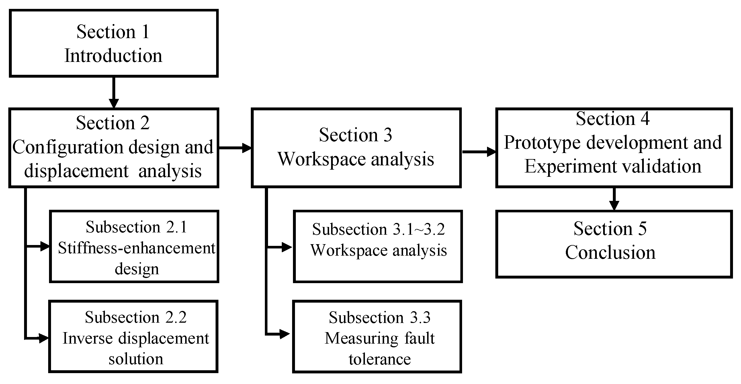
Figure 1. The workflow chart of this paper.
Machines 10 00088 g001
Figure 2. Stiffness-enhanced structure with redundant passive prismatic joints. L t is the distance between the base and the moving platform, P denots a passive prismatic joint, P represents an active prismatic joint, and S is a passive spherical joint: (a) Traditional 3-PPS parallel mechanism; (b) Stiffness-enhanced 3-PPS parallel mechanism; (c) Diagram of stiffness-enhanced structure.
Machines 10 00088 g002
Figure 3. Underwater vectored thruster based on a horizontally mounted stiffness-enhanced 3-PPS parallel mechanism.
Machines 10 00088 g003
Figure 4. Structural scheme of a 3-PPS parallel mechanism.
Machines 10 00088 g004
Figure 5. The orientation representation diagram of the normal direction of the moving platform.
Machines 10 00088 g005
Figure 6. Keeping the same orientation of the moving platform at different P z positions.
Machines 10 00088 g006
Figure 7. The schematic diagram of equi-volumetric partition method.
Machines 10 00088 g007
Figure 8. The desired workspace of the parallel mechanism, i.e., the tilt angle θ 0 , π / 6 and the azimuth angle α 0 , 2 π .
Machines 10 00088 g008
Figure 9. The distributions of the FTW and the MIW under different failure positions of limb q 1 : (a) λ q 1 = 0 ; (b) λ q 1 = 1 / 4 ; (c) λ q 1 = 1 / 2 ; (d) λ q 1 = 3 / 4 ; (e) λ q 1 = 1 .
Machines 10 00088 g009
Figure 10. The volume of FTW and MIW under different radii of the moving platform. V M r k and V r k , respectively, represent the volume of MIW and FTW when the radius of the moving platform is k.
Machines 10 00088 g010
Figure 11. The minimum stroke of every limb under F T I = θ f 2 / θ d 2 . Region I is the non-single actuator failure region on the left. Region II is the single actuator failure region. Region III is the non-single actuator failure region on the right.
Machines 10 00088 g011
Figure 12. The optimal solution of stroke of all limbs locates in Curve C s .
Machines 10 00088 g012
Figure 13. The prototype of a stiffness-enhanced 3-PPS parallel mechanism applied in underwater vectored thruster.
Machines 10 00088 g013
Figure 14. The laser tracker measures the orientation of the moving platform.
Machines 10 00088 g014
Figure 15. Experiment results v.s. simulation results: (a) failure-free operation; (b) failure in limb q 1 .
Machines 10 00088 g015
Figure 16. The errors between experimental results and simulation results: (a) failure-free operation; (b) failure in limb q 1 .
Machines 10 00088 g016
Table 1. The main technical specification of the stiffness-enhanced 3-PPS parallel mechanism.
SpecificationValue
Maximum tilt angle20
Circumcircle radius of the equilateral triangular P 1 P 2 P 3 95 mm
Root mean square of the fault-tolerant index0.2703
Maximum swing angle of spherical joints45
Stroke of all limbs96 mm
Rated payload2000 N
Repeated orientation accuracy ± 0.018
Maximum operating depth4500 m
Table 2. The measurement data when the limb q 1 is in failure.
LimbDisplacementValue (Start:Step:End)
q 1 q 1 n 15.5 mm
q 2 q 2 n 0:7:70 mm
q 3 q 3 n 0:7:70 mm
Publisher’s Note: MDPI stays neutral with regard to jurisdictional claims in published maps and institutional affiliations.