


Fault-Tolerant Predictive Current Control of Six-Phase PMSMs with a Single Isolated Neutral Configuration


Abstract
1. Introduction
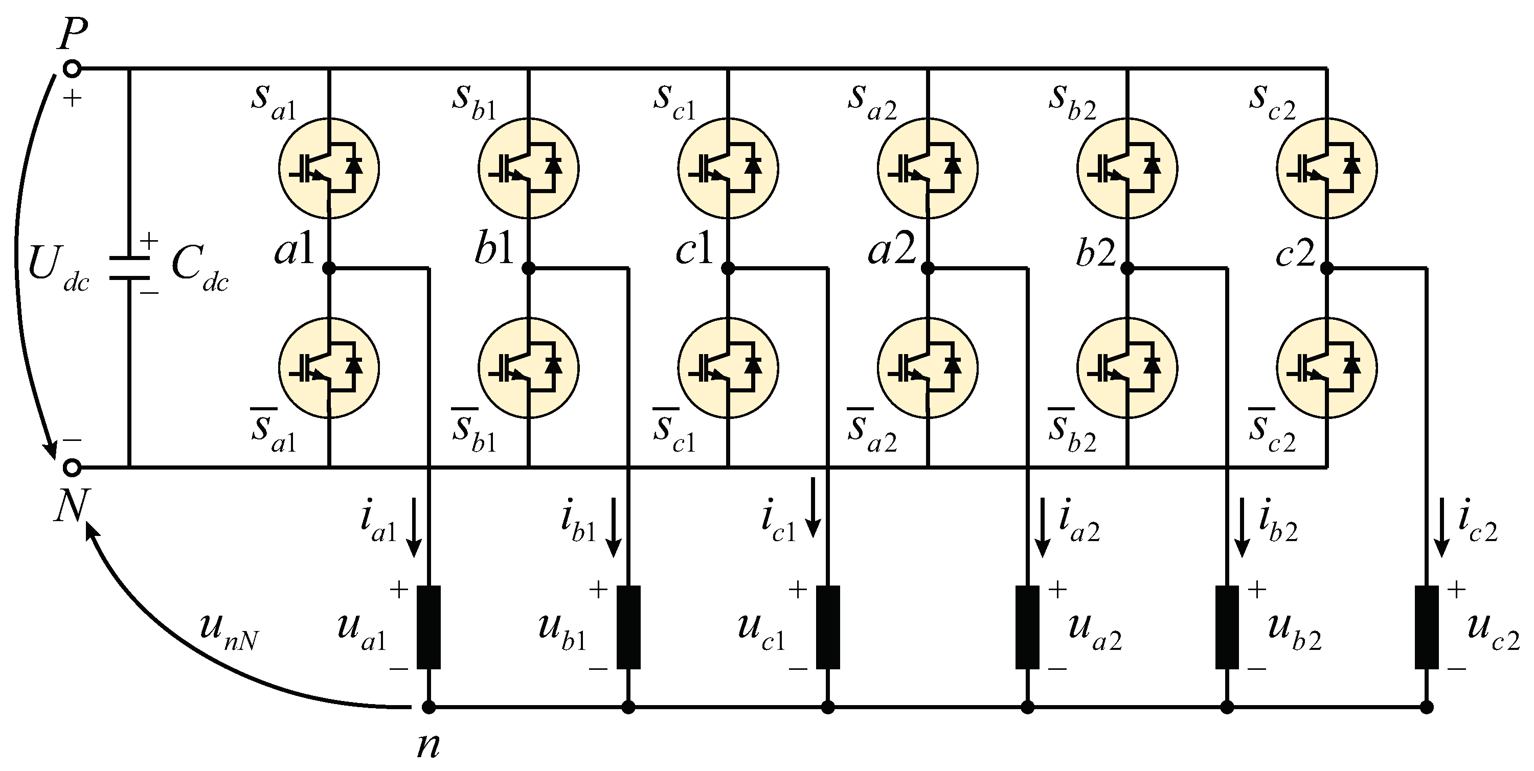
2. System Model
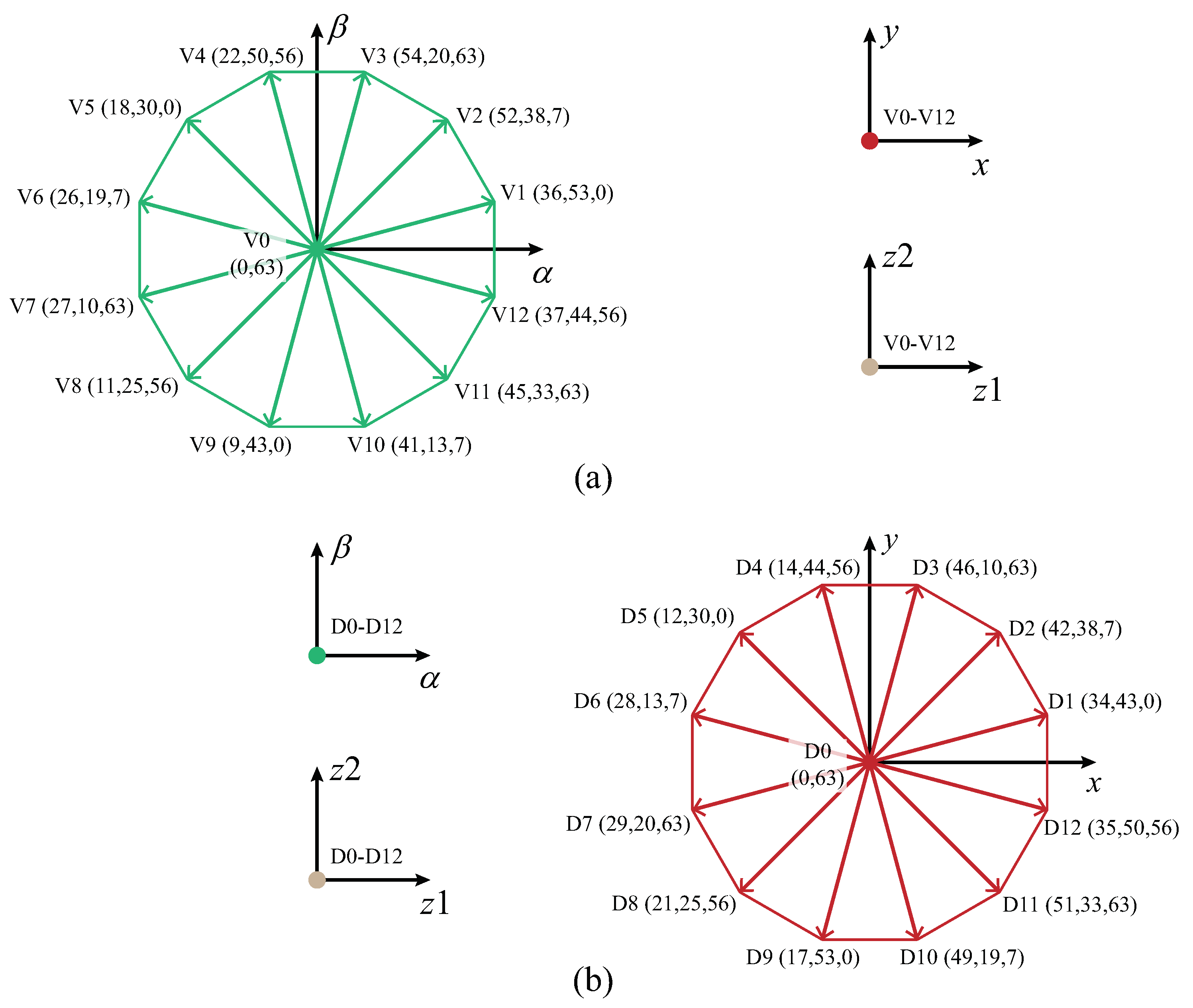
3. Ft-Pcc Strategy
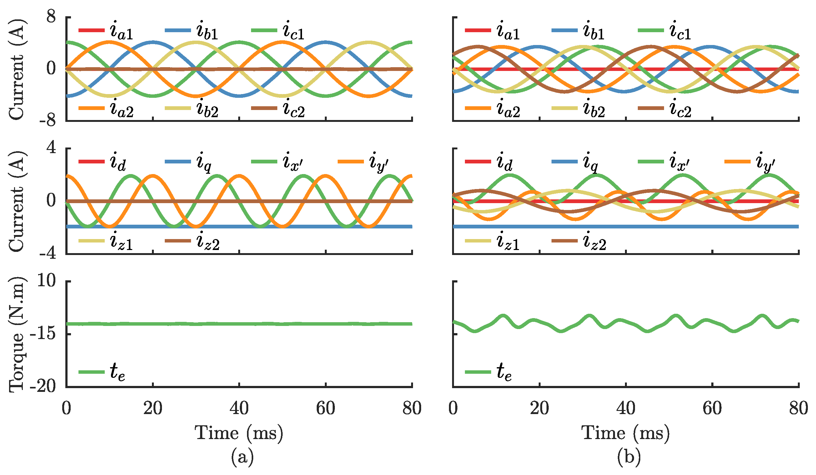
4. Simulation Results
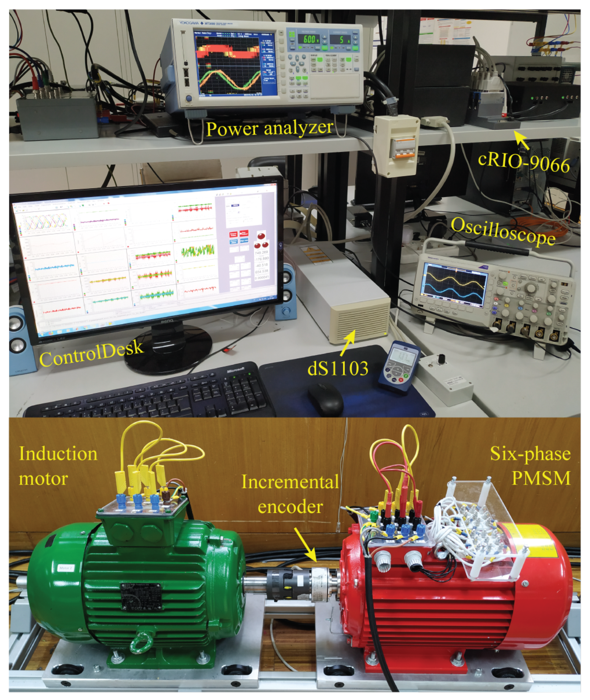
5. Experimental Results
6. Conclusions
Author Contributions
Funding
Data Availability Statement
Conflicts of Interest
Abbreviations
| 2L-VSI | two-level voltage source inverter |
| 1N | single isolated neutral point |
| 2N | two isolated neutral points |
| DOB | disturbance observer |
| FCS-MPC | finite control set model predictive control |
| FT-PCC | fault-tolerant predictive current control |
| IM | induction machine |
| ML | minimum losses |
| MT | maximum torque |
| OPF | open-phase fault |
| PMSM | permanent magnet synchronous machine |
| THD | total harmonic distortion |
| ZSVC | zero-sequence voltage component |
Appendix A
References
- Xu, J.; Guo, S.; Guo, H.; Tian, X. Fault-Tolerant Current Control of Six-Phase Permanent Magnet Motor With Multifrequency Quasi-Proportional-Resonant Control and Feedforward Compensation for Aerospace Drives. IEEE Trans Power Electron. 2023, 38, 283–293. [Google Scholar] [CrossRef]
- Zhao, T.; Wu, S.; Cui, S. Multiphase PMSM with asymmetric windings for more electric aircraft. IEEE Trans. Transp. Electrif. 2020, 6, 1592–1602. [Google Scholar] [CrossRef]
- Tahaa, W.; Azerb, P.; Callegaro, A.D.; Emadi, A. Multiphase Traction Inverters: State-of-the-Art Review and Future Trends. IEEE Access 2022, 10, 4580–4599. [Google Scholar] [CrossRef]
- Barrero, F.; Durán, M.J. Recent advances in the design, modeling, and control of multiphase machines–Part I. IEEE Trans. Ind. Electron. 2016, 63, 449–458. [Google Scholar] [CrossRef]
- Durán, M.J.; Barrero, F. Recent advances in the design, modeling, and control of multiphase machines–Part II. IEEE Trans. Ind. Electron. 2016, 63, 459–468. [Google Scholar] [CrossRef]
- Levi, E. Advances in converter control and innovative exploitation of additional degrees of freedom for multiphase machines. IEEE Trans. Ind. Electron. 2016, 63, 433–448. [Google Scholar] [CrossRef]
- Durán, M.J.; Levi, E.; Barrero, F. Multiphase electric drives: Introduction. In Wiley Encyclopedia of Electrical and Electronics Engineering; Webster, J., Ed.; John Wiley and Sons, Inc.: Hoboken, NJ, USA, 2017; pp. 1–26. [Google Scholar]
- Munim, W.N.W.A.; Durán, M.J.; Che, H.S.; Bermúdez, M.; González-Prieto, I.; Rahim, N.A. A unified analysis of the fault tolerance capability in six-phase induction motor drives. IEEE Trans. Ind. Electron. 2017, 32, 7824–7836. [Google Scholar] [CrossRef]
- Gonçalves, P.; Cruz, S.; Mendes, A. Finite Control Set Model Predictive Control of Six-Phase Asymmetrical Machines—An Overview. Energies 2019, 12, 4693. [Google Scholar] [CrossRef]
- Durán, M.; González-Prieto, I.; González-Prieto, A.; Aciego, J.J. The Evolution of Model Predictive Control in Multiphase Electric Drives: A Growing Field of Research. IEEE Ind. Electron. Mag. 2022. [Google Scholar] [CrossRef]
- Rodriguez, J.; Garcia, C.; Mora, A.; Flores-Bahamonde, F.; Acuna, P.; Novak, M.; Zhang, Y.; Tarisciotti, L.; Davari, A.; Zhang, Z.; et al. Latest Advances of Model Predictive Control in Electrical Drives. Part I: Basic Concepts and Advanced Strategies. IEEE Trans. Ind. Electron. 2022, 37, 3927–3942. [Google Scholar] [CrossRef]
- Rodriguez, J.; Garcia, C.; Mora, A.; Davari, A.; Rodas, J.; Garcia, D.F.V.; Elmorshedy, M.F.; Wang, F.; Zuo, K.; Tarisciotti, L.; et al. Latest Advances of Model Predictive Control in Electrical Drives. Part II: Applications and Benchmarking with Classical Control Methods. IEEE Trans. Ind. Electron. 2022, 37, 5047–5061. [Google Scholar] [CrossRef]
- González-Prieto, I.; Durán, M.J.; Aciego, J.J.; Martin, C.; Barrero, F. Model predictive control of six-phase induction motor drives using virtual voltage vectors. IEEE Trans. Ind. Electron. 2018, 65, 27–37. [Google Scholar] [CrossRef]
- Aciego, J.J.; Prieto, I.G.; Durán, M.J. Model predictive control of six-phase induction motor drives using two virtual voltage vectors. IEEE J. Emerg. Sel. Top. Power Electron. 2019, 7, 321–330. [Google Scholar] [CrossRef]
- González-Prieto, A.; González-Prieto, I.; Durán, M.J. Smart voltage vectors for model predictive control of six-phase electric drives. IEEE Trans. Ind. Electron. 2020, 68, 9024–9035. [Google Scholar] [CrossRef]
- Gonçalves, P.F.C.; Cruz, S.M.A.; Mendes, A.M.S. Bi-subspace predictive current control of six-phase PMSM drives based on virtual vectors with optimal amplitude. IET Electr. Power Appl. 2019, 13, 1672–1683. [Google Scholar] [CrossRef]
- Liu, S.; Liu, C. Virtual-vector-based robust predictive current control for dual three-phase PMSM. IEEE Trans. Ind. Electron. 2021, 68, 2048–2058. [Google Scholar] [CrossRef]
- Gonçalves, P.F.C.; Cruz, S.M.A.; Mendes, A.M.S. Multistage Predictive Current Control Based on Virtual Vectors for the Reduction of Current Harmonics in Six-Phase PMSM. IEEE Trans. Energy Convers. 2021, 36, 1368–1377. [Google Scholar] [CrossRef]
- Gonçalves, P.F.C.; Cruz, S.M.A.; Mendes, A.M.S. Disturbance-Observer-Based Predictive Current Control of Six-Phase PMSMs for the Mitigation of Steady-State Errors and Current Harmonics. IEEE Trans. Ind. Electron. 2022, 69, 130–140. [Google Scholar] [CrossRef]
- Guzman, H.; Durán, M.J.; Barrero, F.; Bogado, B.; Toral, S. Speed control of five-phase induction motors with integrated open-phase fault operation using model-based predictive current control techniques. IEEE Trans. Ind. Electron. 2014, 61, 4474–4484. [Google Scholar] [CrossRef]
- Guzman, H.; Durán, M.J.; Barrero, F.; Zarri, L.; Bogado, B.; Prieto, I.G.; Arahal, M.R. Comparative study of predictive and resonant controllers in fault-tolerant five-phase induction motor drives. IEEE Trans. Ind. Electron. 2016, 63, 606–617. [Google Scholar] [CrossRef]
- Luo, Y.; Liu, C. Pre-and post-fault tolerant operation of a six-phase PMSM motor using FCS-MPC without controller reconfiguration. IEEE Trans. Veh. Technol. 2019, 68, 254–263. [Google Scholar] [CrossRef]
- Bermúdez, M.; Martín, C.; González-Prieto, I.; Durán, M.J.; Arahal, M.R.; Barrero, F. Predictive current control in electrical drives: An illustrated review with case examples using a five-phase induction motor drive with distributed windings. IET Electr. Power Appl. 2020, 14, 1291–1310. [Google Scholar] [CrossRef]
- González-Prieto, A.; González-Prieto, I.; Durán, M.J.; Barrero, F. Efficient model predictive control with natural fault-tolerance in asymmetrical six-phase induction machines. Energies 2019, 12, 3989. [Google Scholar] [CrossRef]
- González-Prieto, I.; Durán, M.J.; Bermúdez, M.; Barrero, F.; Martín, C. Assessment of virtual-voltage-based model predictive controllers in six-phase drives under open-phase faults. IEEE J. Emerg. Sel. Top. Power Electron. 2020, 8, 2634–2644. [Google Scholar] [CrossRef]
- Sun, X.; Li, T.; Tian, X.; Zhu, J. Fault-Tolerant Operation of a Six-Phase Permanent Magnet Synchronous Hub Motor Based on Model Predictive Current Control with Virtual Voltage Vectors. IEEE Trans. Energy Convers. 2022, 37, 337–346. [Google Scholar] [CrossRef]
- Feng, Y.; Liao, Y.; Zhang, X. A Third Harmonic Current Elimination Strategy for Symmetrical Six-Phase Permanent Magnet Synchronous Motor. IEEE Access 2021, 9, 167570–167579. [Google Scholar] [CrossRef]
- Gonçalves, P.F.C.; Cruz, S.M.A.; Mendes, A.M.S. Fixed and Variable Amplitude Virtual Vectors for Model Predictive Control of Six-Phase PMSMs with Single Neutral Configuration. In Proceedings of the 20th International Conference on Industrial Technology (ICIT), Melbourne, VIC, Australia, 13–15 February 2019; IEEE: Piscataway, NJ, USA, 2019; pp. 267–273. [Google Scholar] [CrossRef]


| Parameter | Value | Parameter | Value | Parameter | Value |
|---|---|---|---|---|---|
| (kW) | 4 | p | 2 | (mWb) | 53.3 |
| (V) | 340 | () | 1.6 | (deg) | 0.52 |
| (A) | 3.4 | (mH) | 53.8 | (V) | 650 |
| (rpm) | 1500 | (mH) | 2.1 | (s) | 2.2 |
| (N.m) | 28.4 | (mWb) | 973.7 | (s) | 125 |
| Strategy | Phase | Phase | Phase | Phase | Phase | Phase |
|---|---|---|---|---|---|---|
| FT-PCC (2N) | - | 0.63% | 0.62% | 0.48% | 0.27% | - |
| FT-PCC (1N) | - | 0.54% | 0.89% | 0.42% | 0.47% | 0.88% |
| Strategy | Phase | Phase | Phase | Phase | Phase | Phase |
|---|---|---|---|---|---|---|
| FT-PCC (2N) | - | 0.78% | 0.82% | 0.46% | 0.75% | - |
| FT-PCC (1N) | - | 2.15% | 2.02% | 0.96% | 2.60% | 1.70% |
| Strategy | Phase | Phase | Phase | Phase | Phase | Phase |
|---|---|---|---|---|---|---|
| FT-PCC (1N): OPF in | - | 3.28% | 3.44% | 1.69% | 3.75% | 2.74% |
| FT-PCC (1N): OPF in | 2.83% | 3.72% | 1.27% | 3.38% | 3.73% | - |
Publisher’s Note: MDPI stays neutral with regard to jurisdictional claims in published maps and institutional affiliations. |
© 2022 by the authors. Licensee MDPI, Basel, Switzerland. This article is an open access article distributed under the terms and conditions of the Creative Commons Attribution (CC BY) license (https://creativecommons.org/licenses/by/4.0/).
Share and Cite
Gonçalves, P.; Cruz, S.; Mendes, A. Fault-Tolerant Predictive Current Control of Six-Phase PMSMs with a Single Isolated Neutral Configuration. Machines 2022, 10, 1152. https://doi.org/10.3390/machines10121152
Gonçalves P, Cruz S, Mendes A. Fault-Tolerant Predictive Current Control of Six-Phase PMSMs with a Single Isolated Neutral Configuration. Machines. 2022; 10(12):1152. https://doi.org/10.3390/machines10121152
Chicago/Turabian StyleGonçalves, Pedro, Sérgio Cruz, and André Mendes. 2022. "Fault-Tolerant Predictive Current Control of Six-Phase PMSMs with a Single Isolated Neutral Configuration" Machines 10, no. 12: 1152. https://doi.org/10.3390/machines10121152
APA StyleGonçalves, P., Cruz, S., & Mendes, A. (2022). Fault-Tolerant Predictive Current Control of Six-Phase PMSMs with a Single Isolated Neutral Configuration. Machines, 10(12), 1152. https://doi.org/10.3390/machines10121152