Article

Effect of Groove Texture on Deformation and Sealing Performance of Engine Piston Ring

1
College of Biological and Agricultural Engineering, Jilin University, Changchun 130022, China
2
State Key Laboratory of Power Systems of Tractor, YTO Group Corporation, Luoyang 471039, China
3
School of Intelligent Manufacturing, Nanjing University of Science and Technology, Nanjing 214443, China
4
Department of Ortho and MSK Science, University College London, London HA7 4LP, UK
*
Author to whom correspondence should be addressed.
Machines 2022, 10(11), 1020; https://doi.org/10.3390/machines10111020
Submission received: 7 October 2022 / Revised: 29 October 2022 / Accepted: 1 November 2022 / Published: 3 November 2022
(This article belongs to the Section Vehicle Engineering)

Abstract

:
During the present study, a double groove texture was designed on the surface of a piston ring to improve the sealing performance between the piston ring and cylinder liner. The experimental design method was used to fabricate the test plan according to the groove width, depth, and spacing. By using the thermal–structural coupling analysis method, the finite element analysis of the standard piston ring and the textured piston ring was carried out to simulate the deformation state of the cylinder liner system of the piston ring group during the working stroke. The piston rings with different parameters designed by the test scheme were manufactured by wire electrical discharge machining, and the self-made experiment device carried out the sealing test. The results showed that the groove texture could improve the sealing performance of the piston ring, and the analyzed results demonstrated that the groove texture had little effect on the maximum deformation of the piston ring. Still, it could significantly reduce the minimum deformation of the piston ring group. A piston ring with groove texture would improve the sealing performance and reduce the deformation during the work stroke. During the test, the average deformation of the No.7 piston ring group, with a groove depth of 1 mm, a groove width of 0.5 mm, and a groove spacing of 0.1 mm, was the smallest, about 29.6% lower than that of the standard piston ring group. The sealing performance of the No.7 piston ring group was the best, and the reduction rate of the top gas leakage rate was 52.18%. During the present study, the sealing performance of the piston ring was improved by designing the grooved structure on the piston ring surface, thereby improving the fuel economy and power performance of the engine. The present study could provide a reference for the engineering field to design a piston ring with high sealing performance.

1. Introduction

The internal combustion engine is a thermal engine that directly converts the heat energy released by the combustion of the mixture of fuel and air in the machine into power. Internal combustion engines can provide power for ground machines and vehicles. As the key component of the internal combustion engine, the piston ring group plays an important role in sealing, the formation of lubricating oil film, guiding, etc. [1,2,3,4,5]. The piston ring is close to the inner wall of the cylinder liner of its elastic compensation. During the compression and working stroke, the piston ring is pressed against the inner wall of the cylinder liner and the ring groove by gas pressure. Since the piston rings are broken and have openings, the regular distribution of the upper and lower adjacent piston rings also has a specific sealing effect on the piston [6,7]. The sealing performance of the piston ring is very important to improve the output efficiency of the engine and reduce the emission of pollutants. It also plays a vital role in the energy utilization and environmental protection of the internal combustion engine [8,9,10,11]. Although various energy sources, such as electricity, hydrogen, and biofuels, have begun to be promoted, they have a low starting point and still face huge challenges. By 2040, about 85–90% of transportation energy will still come from internal combustion engines driven by traditional liquid fuels [12].
The failure of the seal between the piston ring and the cylinder liner is a major cause of internal combustion engine failure and one of the reasons for increased vehicle emissions [12,13,14]. Increasing the sealing performance between the piston ring and the cylinder liner is of great significance for improving the efficiency and life of the internal combustion engine. By selecting an appropriate compression ratio and distribution distance for the piston ring, the sealing characteristics can be improved, and leakage loss can be reduced [7,8,15,16]. Researchers have improved the sealing performance of the piston ring by changing the distribution spacing, material, and coating of the piston ring surface [17,18,19,20,21,22,23]. For example, Delprete et al. [24] studied the effect of ring gap, ring mass, elastic properties, and ring static torsional parameters on piston ring sealing efficiency.
Meanwhile, researchers have committed to using simulation methods to analyze the sealing performance of piston rings [25,26,27,28]. For example, Atkinson et al. [25] developed PRIME 3D software to solve the physics of compressible fluid flow through piston and ring closure gaps under engine operating conditions. Dai et al. [28] studied the sealing properties of piston rings through numerical analysis and thermal–structural coupling methods. With the continuous development of processing technology, surface texture has been widely used to improve piston rings’ sealing and friction performance [29,30,31,32,33,34,35,36,37], and the texture types mainly include groove shape and pit shape [37].
During the present study, the groove texture design was carried out on the surface of the piston ring. The test scheme was compiled by using the design of experiment method, and the structural parameters of the groove on the piston ring were designed. The sealing performance of piston rings with different parameters was tested by using a self-made test device. The present research could provide a piston ring with high sealing properties for the engineering field, improve the working efficiency of the internal combustion engine, and reduce the emission of harmful substances.

2. Design Groove Morphology on the Piston Ring Surface

In the present study, the Volkswagen EA211 1.4L 66kW MPI low-power engine was taken as the combustion engine, and the groove texture was designed on the surface of the piston ring. The engine piston and piston ring group were scanned by a hand-held 3D laser scanner (purchased from Creaform Co. Ltd., UNIscan of HandyScan, Lévis, QC, Canada) to obtain the point clouds. After the point clouds were processed by the software, the three-dimensional model of the piston and piston ring was established. The optical resolution of the scanner was 0.1 mm. As shown in Figure 1, the annular rectangular groove was machined on the side of the piston ring, and the groove dimensions were depth D, width W, and groove spacing L.
Based on the size of the piston rings during the present study, the groove size parameters of the piston rings were selected as the experiment factors, and the level values of the designed factors are shown in Table 1.
The test plan was compiled by the test design method [38] to carry out a comprehensive test. Twenty-seven piston rings with different groove size parameters were designed, and the sealing performance was compared with that of the standard piston rings. The design parameters with different groove structures on the piston ring surface are shown in Table 2.
After investigation and consultation, the piston ring material of the Volkswagen EA211 1.4 L 66 kW MPI low-power engine during the present study was 1Cr13, and the piston material was ZL108.

3. Finite Element Analysis of Piston Ring

3.1. Analytical Models for Engine Piston and Piston Rings

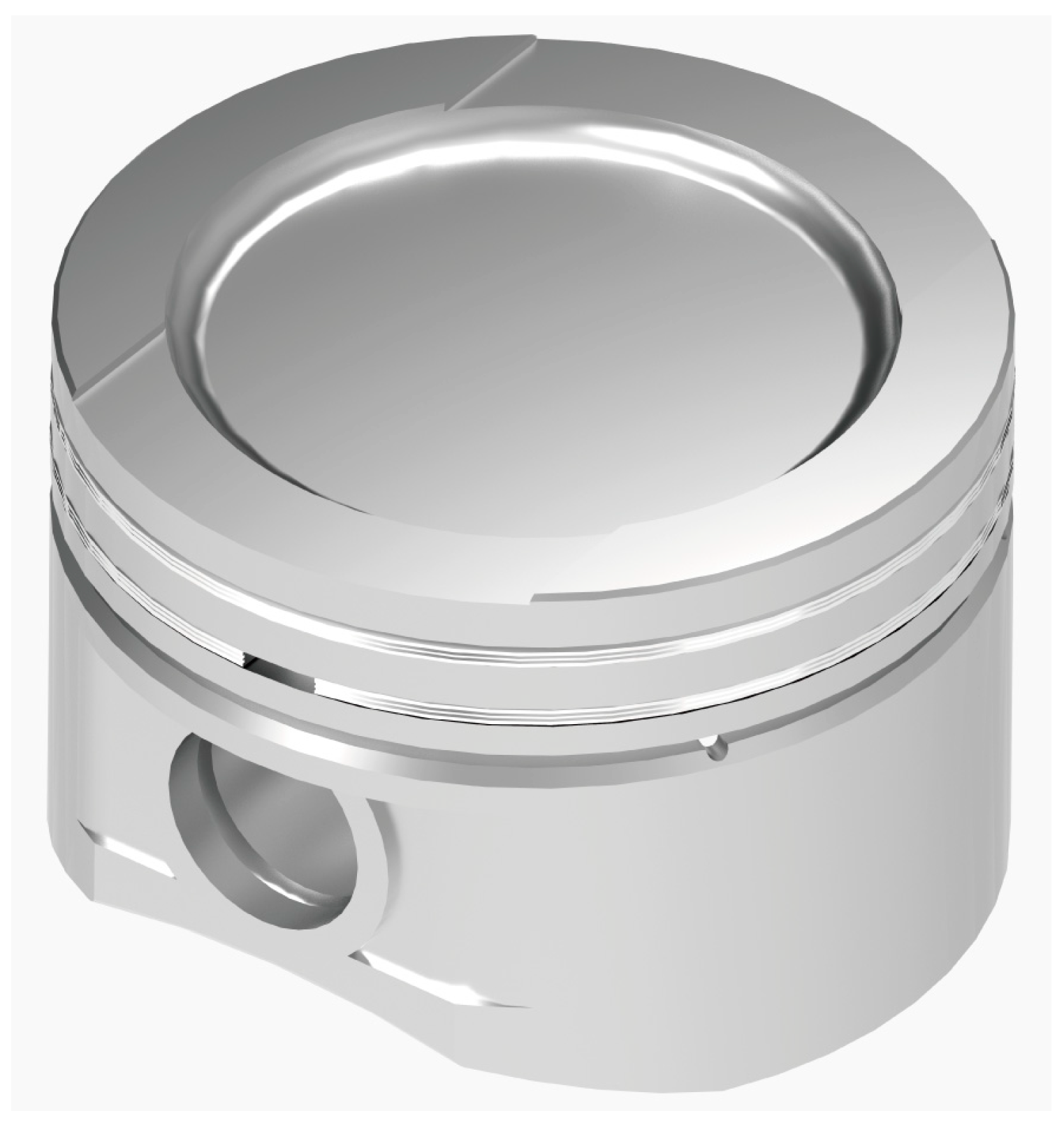
The engine piston and piston ring were scanned, and the model was reconstructed. The piston and piston ring were assembled using 2016-Solidworks (Dassault Systemes, USA) software according to the actual model, as shown in Figure 2.
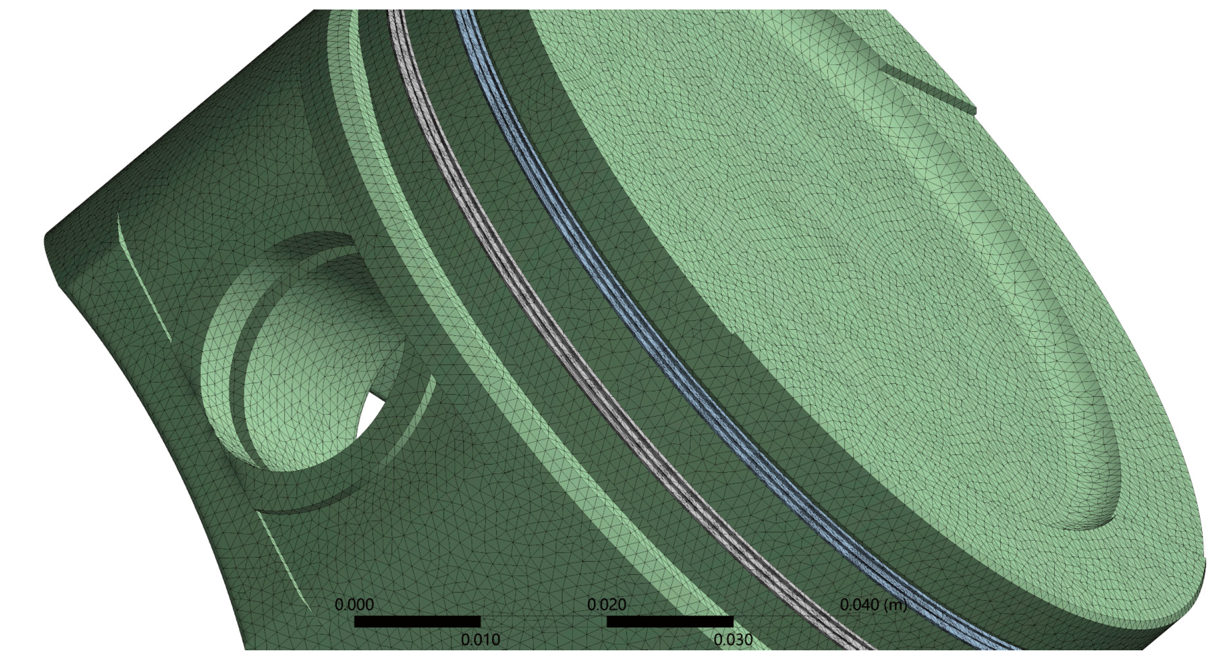
Due to the complexity of the working conditions of the piston, the thermal–structural coupling finite element simulation method was used to analyze the deformation of the piston during the power stroke. The model shown in Figure 2 was imported into ANSYS software, and the materials of the piston and piston ring were set with the engineering data of ANSYS software. The hexahedron-dominant method was used to divide the mesh of the piston and piston ring. The mesh size was 1 mm, and the piston ring and groove texture position were refined locally with a mesh of level two. After the assembly of piston ring No. 7 and the piston, the mesh model was generated, as shown in Figure 3.

3.2. Boundary Conditions for Analysis Models

When performing finite element analysis, it is necessary to determine the boundary conditions of the analysis model. Because the working conditions of the engine are variable and complex, the boundary conditions in the process of the power stroke of the piston and piston ring are simplified. In the present study, the method of heat–structure coupling was used to simulate and analyze the moving components of the piston assembly. Firstly, the temperature field of the engine piston and piston rings during the power stroke was calculated. The analysis result was taken as one of the boundary conditions of the mechanical analysis and imported into the corresponding analysis module to simulate the deformation of the piston and piston ring during the work-forming process.
The steady-state temperature field was calculated using the third type of thermal boundary conditions, and the boundary conditions and initial conditions were determined. During the power stroke, the high-temperature and high-pressure gas in the piston ring group and cylinder liner system would first act on the top of the piston. The gas with high temperature and pressure pushed the engine piston to work and transfer heat. The heat transfer coefficient αg at the top of the piston was calculated using the Eickelberg equation, shown in Equation (1):
α g = K 0 C m 3 P g T g
where αg is the convective heat transfer coefficient of the mixed gas at the top of the piston, W/(m2·K). K0 is the correction factor. Pg is the instantaneous pressure of the gas at the top of the piston and can be obtained from the indicator diagram of the engine, Mpa. Tg is the instantaneous temperature of the gas at the top of the piston, K. Cm is the average speed of the engine piston, m/s, and can be calculated by Equation (2):
C m = 2 S t = S n 30
where S is the engine piston stroke, m; T is the time taken for the piston to run one cycle, s; and n is the crankshaft speed, r/min.
The average convection heat transfer coefficient of gas at the top of the piston, αm, and the average temperature, Tm, during one cycle of engine piston operation can be obtained by Equations (3) and (4):
α m = 1 4 π 0 4 π α g d φ
T m = 0 4 π ( α g + T g ) d φ 0 4 π α g d φ
where φ is the rotation angle of the crankshaft, rad.
Based on the reference [39], the heat transfer coefficient of the piston junk, piston ring zone, and piston bottom was calculated by Equation (5):
1 α n = δ i λ i + 1 α w
where δi is the thickness of the oil film, piston ring, and cylinder liner, m, and λi is the corresponding heat transfer coefficient. αw is the heat exchange coefficient between the cylinder liner and the cooling water, which is calculated according to Equation (6):
α w = 300 + 1800 G v A
where Gv is the flow of cooling water, m3/s; A is the average sectional area of the water cooling groove of the cylinder liner.
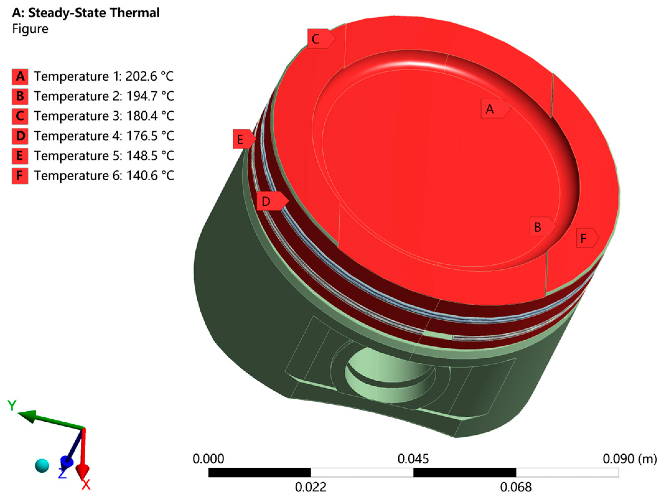
According to Equations (1)–(6) and the engine design parameters, the average temperature of the piston rings and engine piston was calculated during the power stroke. The calculated results were applied to the engine piston and piston rings with ANSYS software. The steady-state temperature field of the system composed of piston rings and a cylinder liner system is shown in Figure 4.
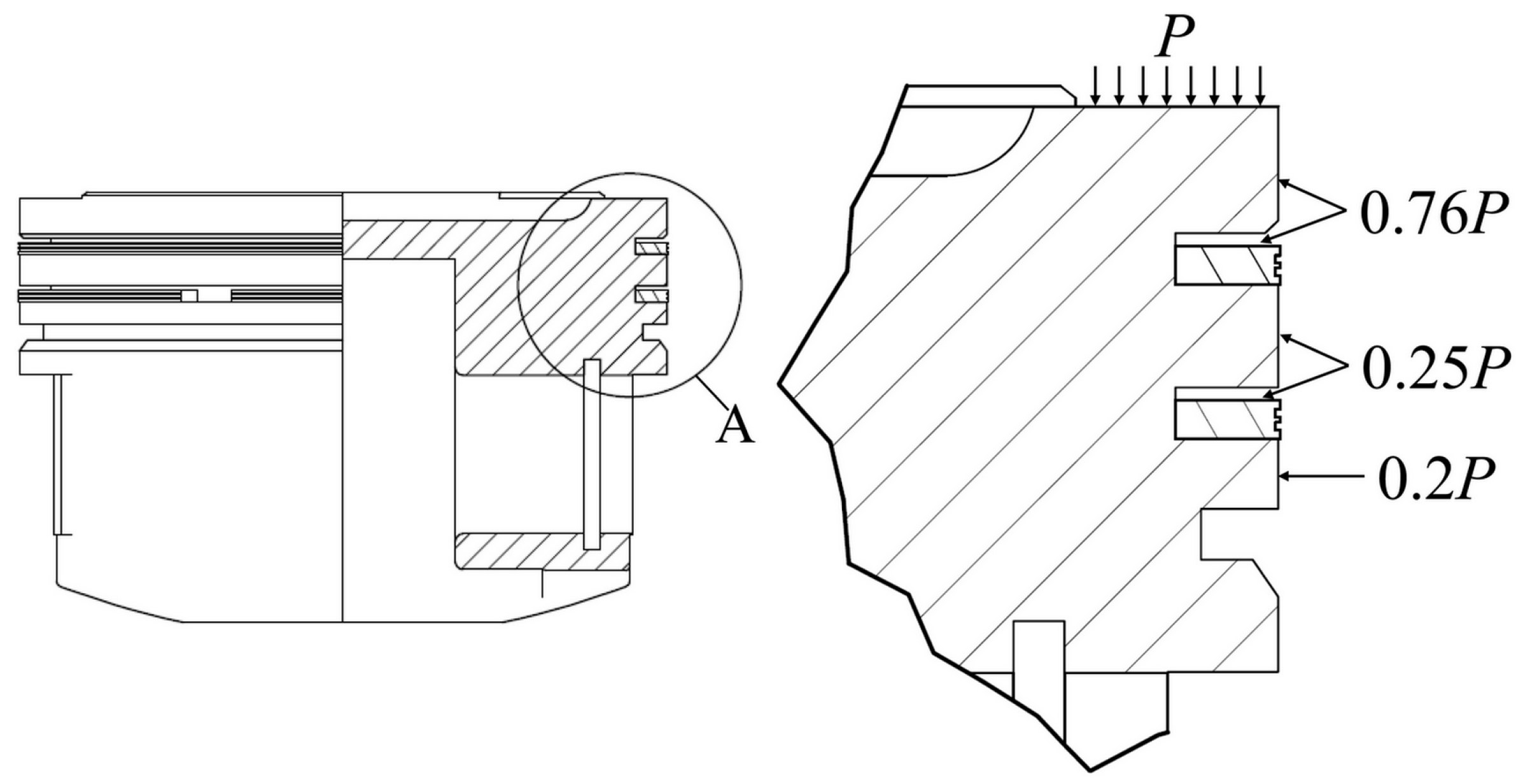
When the compressed gas in the engine was ignited, the axial gas pressure, reciprocating inertia force, and radial pressure were applied to the piston rings during the power stroke process. During the power stroke process, the high-temperature and high-pressure gas acting on the top of the engine piston was transferred to the piston ring surface in a certain proportion [40]. The pressure distribution of the engine piston and piston rings is shown in Figure 5, wherein P is about 10 Mpa according to the engine indicator diagram.
According to the operational characteristics of the engine piston, the piston ring and piston are driven by the connecting rod to make a reciprocating linear motion along the cylinder liner axis, and they are subject to the reciprocating inertial force Fj, as shown in Equation (7):
F j = m j α j = m j r ω 2 ( cos θ + l cos 2 θ )
where mj is the mass of the piston ring group, kg. αj is the acceleration of the piston ring group in the reciprocating process, m/s2. θ is the angle of crankshaft rotation, rad. l is the length of the connecting rod, m. ω is the rotational angular velocity of the crankshaft, rad/s.
Meanwhile, the piston ring group reciprocates in the cylinder liner and generates side pressure under the action of the crank and connecting rod mechanism. This makes the piston ring group produce a second-order movement and greatly impacts the radial direction of the piston ring. The reaction force of the connecting rod on the piston ring group can be divided into axial force and radial force. The radial force pressing against the cylinder liner is the lateral pressure, which can be calculated by Equation (8):
F n = F tan α
where F is the resultant force of gas pressure and inertia force acting on the piston ring, N. α is the swing angle of the connecting rod, rad.

4. Finite Element Analysis Results

Based on the characteristic parameters of the engine used in the test and the above equations, the deformation of the piston ring during the power stroke of the piston was analyzed by using the thermal–structural coupling method. The maximum and minimum deformations of the standard piston rings and grooved piston rings in the test are shown in Figure 6.
Compared to the maximum deformation of standard piston rings, the maximum deformation of 27 kinds of piston rings with the groove texture had no significant change. Among them, the largest deformation of the No. 7 and No. 26 piston ring groups was the smallest overall. However, it can be seen from Figure 6 that the groove texture could significantly reduce the minimum deformation of piston rings, and the gap between the minimum deformation of the groove-textured piston rings with different design parameters was similar.
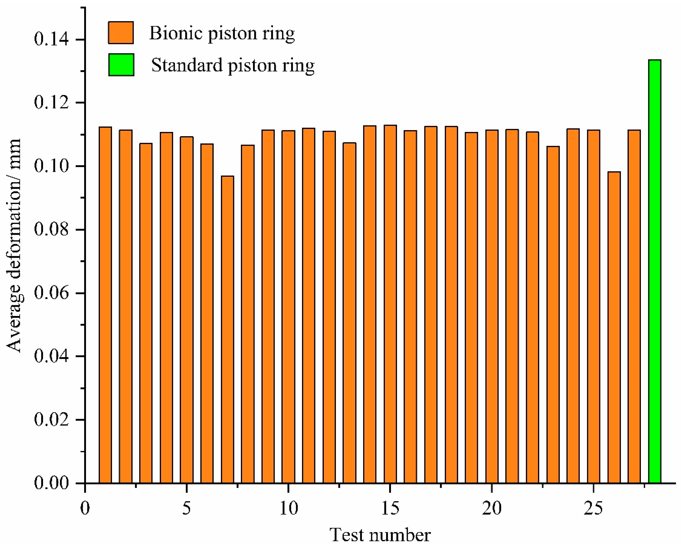
According to the analysis results in Figure 6, the average deformation of the standard piston ring and the piston ring with the groove texture during the power stroke was calculated, as shown in Figure 7. The average deformation of the piston rings with the groove texture was significantly lower than that of the standard piston ring. This showed that the groove texture could improve the strength of the piston ring and reduce the deformation of the piston ring during the power stroke. Thus, the sealing performance of the piston ring could be improved.
Among 27 kinds of piston rings with different groove texture parameters, the average deformation of the No. 7 and No. 26 piston rings was small. The average deformation of piston ring No. 7 was the smallest, about 29.6% lower than the standard piston ring, as shown in Figure 8.

5. Piston Ring Sealing Performance Test

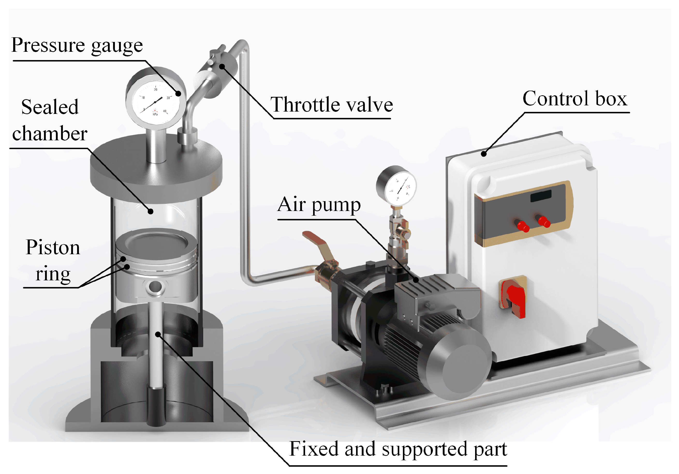
To verify the sealing performance of textured piston rings, a static seal test device for piston rings was self-built during the present study, as shown in Figure 9. The inner diameter of the sealing chamber was the same as that of the engine cylinder liner during the test. The piston rings in the engine were used as the base, and the grooves were machined on the piston ring surface according to the design parameters of the piston ring grooves of No. 7 and No. 26. During the test, the grooves on the piston ring surface were machined by wire electrical discharge machining. The burr on the groove edge was removed, and the edge of the groove was grinded to avoid affecting the test results. The standard piston ring, piston ring No. 26, and piston ring No. 7 were assembled with the engine piston respectively. The sealing chamber was pressurized by an air pump.
Before the static seal test, the piston ring surface should be thoroughly cleaned with an ultrasonic cleaner. Then, the piston ring group surface should be evenly coated with lubricating oil for installation. At the beginning of the test, the throttle valve was opened, and the pressurized gas was injected into the sealing chamber. The throttle valve was closed when the pressure in the space at the top of the engine piston reached 0.8 Mpa, and the closing time was recorded. The gas leakage time in the sealing chamber was recorded, and the time was recorded when the pressure dropped by 0.05 Mpa. The static sealing performance of each piston ring was repeatedly tested, and the average value was calculated. The change in gas pressure at the top of the engine piston is shown in Figure 10.
It can be seen from Figure 10 that the gas pressure at the top of the piston ring group decreased gradually. When the pressure change curve slope was large, it indicated that the piston ring had poor sealing performance. It can be seen from Figure 10 that piston rings No. 7 and No. 26 had similar sealing performances, superior to the sealing performance of standard piston rings. The average air leakage rate of each piston ring was based on Equation (9):
v = P t
where P is the initial pressure of the sealing chamber, Pa. t is the time when the pressure in the sealing chamber decreases from the initial state to the ambient pressure.
According to Equation (10), the average air leakage rate of the piston ring with groove texture was relative to the average air leakage rate of the standard piston ring.
δ = v standard v g r o o v e v standard × 100 %
The experimental results are shown in Table 3. Compared to the sealing performance of standard piston rings, piston ring No. 7, with a groove depth of 1 mm, a width of 0.5 mm, and spacing of 0.1 mm, could significantly reduce the gas leakage rate, and the sealing performance was improved. The average reduction rate of piston ring No. 7, δ, was 55.26%. The sealing performance of the No. 26 piston ring group was close to that of the No. 7 piston ring group, and the rate reduction rate was 52.29%. No. 26 could also greatly improve the sealing performance of piston rings. The static sealing performance test results of the piston rings were consistent with the thermal–structural coupling finite element analysis results.

6. Conclusions

The groove texture was designed on the surface of the piston ring to improve the sealing performance. The depth, width, and spacing of the groove texture were selected to design the test scheme, the piston ring was constructed according to the design parameters, and the finite element analysis was carried out. Groove texture had little effect on the maximum deformation of the piston ring, but it could significantly reduce the minimum deformation of the piston ring. Meanwhile, the groove texture could improve the strength of the piston ring. Due to reducing the deformation of the piston ring during the power stroke, the sealing performance of the piston ring was improved.
The average deformation of piston ring No. 7, with a groove depth of 1 mm, a width of 0.5 mm, and a spacing of 0.1 mm, was the smallest, which was about 29.6% lower than the standard piston ring. Piston ring No. 7 had the best sealing performance during the experiment, and the average pressure reduction rate of piston ring No. 7 increased by 55.26% compared to the average pressure reduction rate of the standard piston ring. During the present study, the piston ring sealing performance was improved by designing a groove texture on the piston ring to reduce the deformation of the piston ring during the work stroke without changing the material and structure of the piston ring. The present study could provide a reference for the engineering field to design a piston ring with high sealing performance. Meanwhile, it could help to improve the fuel economy of the engine and the power performance of the vehicle.

Author Contributions

Conceptualization, T.C., L.W., J.X., T.G., X.Q. and Q.C.; methodology, T.C., L.W., T.G., X.Y., Q.C., J.J. and C.L.; software, T.C., L.W., T.G. and X.Y.; validation, T.C., J.X. and X.Q.; formal analysis, T.C., L.W., T.G., X.Y., J.J. and C.L.; investigation, T.C., L.W. and Q.C.; resources, L.W. and Q.C.; data curation, T.C., J.X., X.Q., T.G. and Q.C.; writing—original draft preparation, T.C.; writing—review and editing, T.C., Q.C. and C.L.; visualization, T.C., J.X., T.G., X.Q. and Q.C.; supervision, T.C. and Q.C.; project administration, T.C. All authors have read and agreed to the published version of the manuscript.

Funding

This research was supported by the State Key Laboratory of Power Systems of Tractor, China, grant number SKT2022002.

Institutional Review Board Statement

Not applicable.

Informed Consent Statement

Not applicable.

Data Availability Statement

The data supporting the findings of this study are available in the article.

Conflicts of Interest

On behalf of all authors, the corresponding author states that there is no conflict of interest. The funder had no role in the test design, collection, analyses, or interpretation of data, in the writing of the manuscript, or in the decision to publish the results.

References

  1. Dellis, P.S. Effect of friction force between piston rings and liner: A parametric study of speed, load, temperature, piston-ring curvature, and high-temperature, high-shear viscosity. Proc. Inst. Mech. Eng. Part J J. Eng. Tribol. 2010, 224, 411–426. [Google Scholar] [CrossRef]
  2. Dellis, P.S.; Arcoumanis, C. A parametric study on oil film pressure measurements in a single piston-ring configuration. Int. J. Engine Res. 2013, 14, 122–137. [Google Scholar] [CrossRef]
  3. Dellis, P.S. Piston-ring performance: Limitations from cavitation and friction. Int. J. Struct. Integr. 2019, 10, 304–324. [Google Scholar] [CrossRef]
  4. Priest, M.; Dowson, D.; Taylor, C.M. Theoretical modelling of cavitation in piston ring lubrication. Proc. Inst. Mech. Eng. Part C J. Mech. Eng. Sci. 2000, 214, 435–447. [Google Scholar] [CrossRef]
  5. Sun, J.; Zhang, X.; Zhu, J.; Gao, Y.; Wang, H.; Zhao, X.; Teng, Q.; Ren, Y.; Zhu, G. On the lubrication characteristics of piston ring under different engine operation conditions. Ind. Lubr. Tribol. 2020, 72, 101–108. [Google Scholar] [CrossRef]
  6. Kagnici, F.; Akalin, O. The Effect of Cylinder Bore Distortion on Lube Oil Consumption and Blow-By. J. Tribol. Trans. ASME 2014, 136, 011103. [Google Scholar] [CrossRef]
  7. Rabute, R.; Tian, T. Challenges involved in piston top ring designs for modern SI engines. J. Eng. Gas Turbines Power Trans. ASME 2001, 123, 448–459. [Google Scholar] [CrossRef]
  8. Morris, N.; Mohammadpour, M.; Rahmani, R.; Rahnejat, H. Optimisation of the piston compression ring for improved energy efficiency of high performance race engines. Proc. Inst. Mech. Eng. Part D J. Automob. Eng. 2017, 231, 1806–1817. [Google Scholar] [CrossRef] [Green Version]
  9. Tung, S.C.; McMillan, M.L. Automotive tribology overview of current advances and challenges for the future. Tribol. Int. 2004, 37, 517–536. [Google Scholar] [CrossRef]
  10. Taylor, R.I.; Evans, P.G. In-situ piston measurements. Proc. Inst. Mech. Eng. Part J J. Eng. Tribol. 2004, 218, 185–200. [Google Scholar] [CrossRef]
  11. Xu, B.; Yin, B.; Gao, D.; Hua, X. Tribological performance of surface treated piston assembly with infiltrated layer. J. Mech. Sci. Technol. 2022, 36, 197–204. [Google Scholar] [CrossRef]
  12. Wang, Z.; Shuai, S.; Li, Z.; Yu, W. A Review of Energy Loss Reduction Technologies for Internal Combustion Engines to Improve Brake Thermal Efficiency. Energies 2021, 14, 6656. [Google Scholar] [CrossRef]
  13. García, C.; Rojas, J.; Abril, S. Analysis of the Influence of Textured Surfaces and Lubrication Conditions on the Tribological Performance between the Compression Ring and Cylinder Liner. Lubricants 2021, 9, 51. [Google Scholar] [CrossRef]
  14. Meng, F.-M.; Wang, J.-X.; Xiao, K. A study of the influences of particles in the gas flow passage of a piston ring pack on the tribological performances of the piston ring. Proc. Inst. Mech. Eng. Part C J. Mech. Eng. Sci. 2010, 224, 201–215. [Google Scholar] [CrossRef]
  15. Mahmoud, K.G.; Knaus, O.; Parikyan, T.; Offner, G.; Sklepic, S. An integrated model for the performance of piston ring pack in internal combustion engines. Proc. Inst. Mech. Eng. Part K J. Multi-Body Dyn. 2018, 232, 371–384. [Google Scholar] [CrossRef]
  16. Shen, C.; Khonsari, M.M. Tribological and Sealing Performance of Laser Pocketed Piston Rings in a Diesel Engine. Tribol. Lett. 2016, 64, 26. [Google Scholar] [CrossRef]
  17. Ferreira, R.; Martins, J.; Carvalho, Ó.; Sobral, L.; Carvalho, S.; Silva, F. Tribological solutions for engine piston ring surfaces: An overview on the materials and manufacturing. Mater. Manuf. Process. 2019, 35, 498–520. [Google Scholar] [CrossRef]
  18. Madej, M.; Ozimina, D.; Gałuszka, R.; Gałuszka, G. Corrosion, friction and wear performance of diamond–Like carbon (DLC) coatings. Metalurgija 2016, 55, 679–682. [Google Scholar]
  19. Mustafi, L.; Rahman, M.M.; Al Nasim, M.N.E.A.; Chowdhury, M.A.; Monir, M.H. Deposition behavior and tribological properties of diamond-like carbon coatings on stainless steels via chemical vapor deposition. Int. J. Miner. Met. Mater. 2018, 25, 1335–1343. [Google Scholar] [CrossRef]
  20. Özkan, D.; Erarslan, Y.; Kıncal, C.; Gürlü, O.; Yağcı, M.B. Wear and corrosion resistance enhancement of chromium surfaces through graphene oxide coating. Surf. Coat. Technol. 2020, 391, 125595. [Google Scholar] [CrossRef]
  21. Vysotina, E.A.; Kazakov, V.A.; Polyansky, M.N.; Savushkina, S.V.; Sivtsov, K.I.; Sigalaev, S.K.; Lyakhovetsky, M.A.; Mironova, S.A.; Zilova, O.S. Investigation of the Structure and Functional Properties of Diamond-Like Coatings Obtained by Physical Vapor Deposition. J. Surf. Investig. 2017, 11, 1177–1184. [Google Scholar] [CrossRef]
  22. Vahidi, A.; Fonseca, D.; Oliveira, J.; Cavaleiro, A.; Ramalho, A.; Ferreira, F. Advanced tribological characterization of DLC coatings produced by Ne-HiPIMS for the application on the piston rings of internal combustion engines. Appl. Sci. 2021, 11, 10498. [Google Scholar] [CrossRef]
  23. Volokitina, I.; Siziakova, E.; Fediuk, R.; Kolesnikov, A. Development of a Thermomechanical Treatment Mode for Stainless-Steel Rings. Materials 2022, 15, 4930. [Google Scholar] [CrossRef] [PubMed]
  24. Delprete, C.; Selmani, E.; Bisha, A. Gas escape to crankcase: Impact of system parameters on sealing behavior of a piston cylinder ring pack. Int. J. Energy Environ. Eng. 2019, 10, 207–220. [Google Scholar] [CrossRef] [Green Version]
  25. Atkinson, S. Software accurately predicts piston and ring pack performance. Seal. Technol. 2019, 2019, 5. [Google Scholar] [CrossRef]
  26. Livanos, G.A.; Kyrtatos, N.P. Friction model of a marine diesel engine piston assembly. Tribol. Int. 2007, 40, 1441–1453. [Google Scholar] [CrossRef]
  27. Koszalka, G.; Guzik, M. Mathematical Model of Piston Ring Sealing in Combustion Engine. Pol. Marit. Res. 2014, 21, 66–78. [Google Scholar] [CrossRef] [Green Version]
  28. Dai, Q.W.; Li, S.Y.; Wang, X.Y.; Huang, W.; Wang, X.L. Surface texturing of different sealing materials and their lubrication and sealing performances. China Surf. Eng. 2019, 32, 21–29. [Google Scholar]
  29. Bathe, R.N.; Padmanabham, G.; Thirumalini, S.; Vignesh, R.V. Impact of laser surface texturing (LST) on the tribological characteristics of piston rings and cylinder liners—A review. Part 2: Application of the process. Trans. Inst. Met. Finish. 2022, 100, 119–127. [Google Scholar] [CrossRef]
  30. He, D.; Han, X.; Chen, G.; Wang, Z.; Chen, W.; Xu, J. Effect of geometrical morphology and arrangement of micro-texture on friction property of CKS piston ring. China Surf. Eng. 2021, 34, 59–69. [Google Scholar]
  31. Lu, P.; Wood, R.J.K. Tribological performance of surface texturing in mechanical applications—A review. Surf. Topogr. Metrol. Prop. 2020, 8, 043001. [Google Scholar] [CrossRef]
  32. Pawlus, P.; Reizer, R. Functional importance of honed cylinder liner surface texture: A review. Tribol. Int. 2022, 167, 107409. [Google Scholar] [CrossRef]
  33. Miao, J.; Li, Y.; Rao, X.; Zhu, L.; Guo, Z.; Yuan, C. Effects of different surface grooved cylinder liner on the tribological performance for cylinder liner-piston ring components. Ind. Lubr. Tribol. 2020, 72, 581–588. [Google Scholar] [CrossRef]
  34. Ryk, G.; Etsion, I. Testing piston rings with partial laser surface texturing for friction reduction. Wear 2006, 261, 792–796. [Google Scholar] [CrossRef]
  35. Rao, X.; Sheng, C.; Guo, Z. The influence of different surface textures on wears in cylinder liner piston rings. Surf. Topogr. Metrol. Prop. 2019, 7, 045011. [Google Scholar] [CrossRef]
  36. Xu, B.; Yin, B.; Jia, H.; Hua, X.; Wei, M. Effects of liner surface textures on the tribological performance of different production piston rings. Lubr. Sci. 2020, 34, 356–368. [Google Scholar] [CrossRef]
  37. Yang, C.Z.; Guo, Z.; Xu, C. Effect of grooved cylinder liner depths on the tribological performances of cylinder liner-piston ring. Ind. Lubr. Tribol. 2019, 72, 465–471. [Google Scholar] [CrossRef]
  38. Ren, L.Q. Regression Design and Optimization, 1st ed.; Science Press: Beijing, China, 2009. [Google Scholar]
  39. Golovitchev, V.I.; Yang, J. Construction of combustion models for rapeseed methyl ester bio-diesel fuel for internal combustion engine applications. Biotechnol. Adv. 2009, 27, 641–655. [Google Scholar] [CrossRef]
  40. Depcik, C.; Assanis, D. A universal heat transfer correlation for intake and exhaust flows in an spark-ignition internal combustion engine. SAE Trans. 2002, 111, 734–740. [Google Scholar]
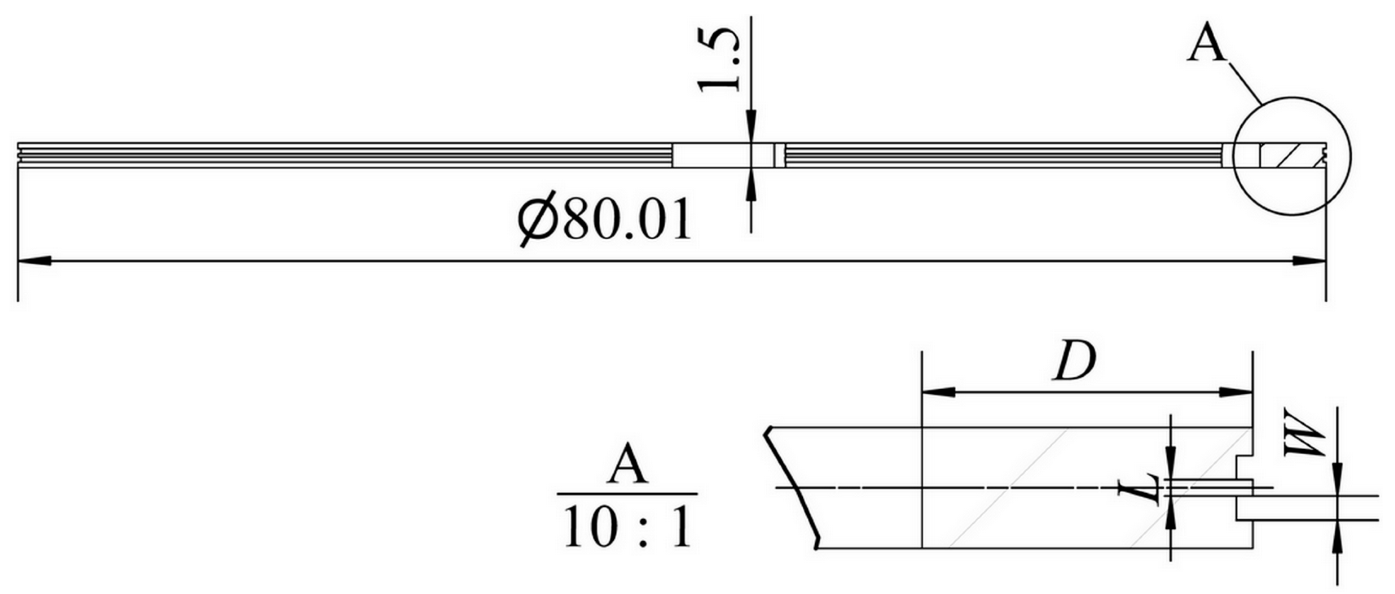
Figure 1. Piston ring with groove texture.
Machines 10 01020 g001
Figure 2. Piston ring group and piston assembly model.
Machines 10 01020 g002
Figure 3. Mesh divided after piston and piston ring assembly.
Machines 10 01020 g003
Figure 4. Temperature boundary conditions of the engine piston and piston rings.
Machines 10 01020 g004
Figure 5. Pressure distribution of piston ring group and cylinder liner system.
Machines 10 01020 g005
Figure 6. Maximum and minimum deformation of the piston ring group.
Machines 10 01020 g006
Figure 7. Average deformation of the piston ring group.
Machines 10 01020 g007
Figure 8. Deformation of piston ring group: (a) standard piston ring group and (b) piston ring No. 7 with groove texture.
Machines 10 01020 g008
Figure 9. Static seal test bench for the piston ring.
Machines 10 01020 g009
Figure 10. Change curve of gas pressure in the engine piston’s top chamber.
Machines 10 01020 g010
Table 1. Factors and levels table of piston ring groove texture.
LevelDepthWidthSpacing
D/mmW/mmL/mm
11 (1)0.1 (1)0.1 (1)
22 (2)0.3 (2)0.2 (2)
33 (3)0.5 (3)0.3 (3)
Table 2. Factor, level, and test number.
Test No.D (mm)W (mm)L (mm)Test No.D (mm)W (mm)L (mm)
110.10.11520.30.3
210.10.21620.50.1
310.10.31720.50.2
410.30.11820.50.3
510.30.21930.10.1
610.30.32030.10.2
710.50.12130.10.3
810.50.22230.30.1
910.50.32330.30.2
1020.10.12430.30.3
1120.10.22530.50.1
1220.10.32630.50.2
1320.30.12730.50.3
1420.30.228 (standard piston ring)000
Table 3. Average leakage rate and rate reduction ratio.
NumberLeakage TimeAverage Leakage RateRatio
t/sv/MPa·s−1δ
Standard piston ring222.483595.83/
Piston ring No. 7497.231608.9155.26%
Piston ring No. 26466.271715.7452.29%
Publisher’s Note: MDPI stays neutral with regard to jurisdictional claims in published maps and institutional affiliations.