Article

Multimodal Interface for Human–Robot Collaboration

by
Samu Rautiainen
1,†,
Matteo Pantano
2,3,†,
Konstantinos Traganos
4,
Seyedamir Ahmadi
1,
José Saenz
5,
Wael M. Mohammed
1,* and
Jose L. Martinez Lastra
1
1
FAST-Lab, Faculty of Engineering and Natural Sciences, Tampere University, FI-33720 Tampere, Finland
2
Functional Materials & Manufacturing Processes, Technology Department, Siemens Aktiengesellschaft, D-81739 Munich, Germany
3
Human-Centered Assistive Robotics (HCR), Department of Electrical and Computer Engineering, Technical University of Munich (TUM), D-80333 Munich, Germany
4
School of Industrial Engineering, Eindhoven University of Technology, De Zaale, NL-5600 MB Eindhoven, The Netherlands
5
Business Unit Robotic Systems, Fraunhofer Institute for Factory Operation and Automation IFF, D-39106 Magdeburg, Germany
*
Author to whom correspondence should be addressed.
These authors contributed equally to this work.
Machines 2022, 10(10), 957; https://doi.org/10.3390/machines10100957
Submission received: 25 August 2022 / Revised: 14 October 2022 / Accepted: 17 October 2022 / Published: 20 October 2022
(This article belongs to the Special Issue Intelligent Factory 4.0: Advanced Production and Automation Systems)

Abstract

:
Human–robot collaboration (HRC) is one of the key aspects of Industry 4.0 (I4.0) and requires intuitive modalities for humans to communicate seamlessly with robots, such as speech, touch, or bodily gestures. However, utilizing these modalities is usually not enough to ensure a good user experience and a consideration of the human factors. Therefore, this paper presents a software component, Multi-Modal Offline and Online Programming (M2O2P), which considers such characteristics and establishes a communication channel with a robot with predefined yet configurable hand gestures. The solution was evaluated within a smart factory use case in the Smart Human Oriented Platform for Connected Factories (SHOP4CF) EU project. The evaluation focused on the effects of the gesture personalization on the perceived workload of the users using NASA-TLX and the usability of the component. The results of the study showed that the personalization of the gestures reduced the physical and mental workload and was preferred by the participants, while overall the workload of the tasks did not significantly differ. Furthermore, the high system usability scale (SUS) score of the application, with a mean of 79.25, indicates the overall usability of the component. Additionally, the gesture recognition accuracy of M2O2P was measured as 99.05%, which is similar to the results of state-of-the-art applications.

1. Introduction

In the contemporary world, the mass customization of products is a competitive advantage in the manufacturing domain, yet it is not easily achieved [1]. I4.0 methodologies address this challenge through novel technological concepts such as smart factories, the merging of physical devices with digital systems, and the adaptation of manufacturing systems to human needs, among others [2]. In such regard, HRC is seen as a I4.0 technology, which can combine human flexibility and adaptability with the repeatability and strength of machines, therefore providing a solution for the needs of versatile manufacturing systems [3]. The emergence of HRC systems requires human-friendly communication methods, which can embody an information exchange similar to human–human communication [4]. This type of communication, however, is complex and usually includes touch, speech, and body gestures. The interpretation of such natural interaction methods creates a need for interfaces suitable for HRC systems.
However, when designing HRC systems that utilize interfaces with natural input, it is not sufficient to only focus on the interpretation. Usually, human-related characteristics, i.e., human factors, need to be considered. This is especially the case when the process is designed to be executed with a human in a key role. The human factors in robotics includes concepts such as mental models, the workload, a trust in automation, and situation awareness [5]. On top of the human factors, user experience is a central aspect of a successful human–robot interaction (HRI) [6], and can be enhanced with personalization options [7]. Such a personalization can be applied to HRC interfaces, particularly for situations where operators might behave in different ways due to their background [8]. The need for personalization has been noted in previous research [9], where authors proposed gesture personalization as a future work of interest. The personalization of gestures have been studied previously, such as in [10], where the authors proposed an application for interpreting dynamic personalized gestures. However, the studies were not focusing on the effects of personalization on human factors, and generally studies about personalization, usability, and accessibility in gesture interfaces are limited [11].
This paper presents a multimodal interface for HRI using hand gestures. A glove-based gestural interface was developed in an earlier project (the work done in [12]), which is used as an inspiration for the work in this paper. The proposed interface utilizes a similar smart glove setup, yet it focuses on enhancing the user experience through a graphical user interface (GUI) and presents a modularly integrable component for a system operating in a smart factory. The main goal of this paper is to study the considerations of human factors when using such a gestural interface through user tests. In fact, the evaluation of the proposed component focuses on finding the SUS score and studies the preferability of the personalization of gestures and its effects on the perceived workload when integrated in a smart factory use case.
To present the results of this study, this paper is organized as follows: Section 2 introduces the smart factory concept and the state-of-the-art HRI communication methods, Section 3 presents the proposed method from the component perspective, and Section 4 from the use case perspective. Finally, Section 5 explains the method of evaluation, Section 6 the results and discussion, and Section 7 the conclusions of the research.

2. Literature Review and Related Work

Creating a multimodal application that can fit in a smart factory setup requires research on the methods and concepts in the domain. Such research is presented as follows: Section 2.1 presents the concept of smart factories and Section 2.2. explains the methodologies regarding HRI and HRC and presents the state of the art in natural interfaces.

2.1. Smart Factories

The smart factory is one of the fundamental concepts of I4.0 [2]. Mark Weiser proposed the first interpretation of a smart factory in the early 1990s, whose description for a smart environment was a physical world with daily life objects equipped with and connected to sensors, actuators, and computers within the same network [13]. In [14], the smart factory is described as a manufacturing solution that provides flexible processes and creates a foundation for dynamically changing the manufacturing flows. Both definitions describe a seamlessly connected shop floor that has the capabilities to be agile, flexible, reconfigurable, and modular. Furthermore, smart factories are designed to focus on the needs of humans [15].
On a more technical level, smart factories can be described as a collection of connected, context-aware systems, which have an ability to consume and create context information (e.g., the position or condition of an object) and assist machines and humans in executing tasks [16]. As an enabling technology of smart factories, cyber-physical systems (CPS) provide a means for merging the physical and digital world [17,18,19]. The use of such systems requires a methodology for system integration and interoperability across the shop floor [20]. The major enabling technologies for CPS are the Internet of Things (IoT), cloud computing, service-oriented computing, and artificial intelligence (AI) [21].
CPS do not strictly follow the traditional automation hierarchy pyramid introduced by the IEC:62264-1 standard [22]. The pyramid defines five levels from the top to the bottom: management, planning, supervisory, control, and the field level. The data flow of such systems is vertical and must follow the hierarchy. On the contrary, CPS allows for a communication between any applications, with a disregard for the typical hierarchy levels [23]. The interconnections are established by a shop floor where the actors are connected to the same medium.
Hence, in order to fulfil the adaptability and flexibility requirements of smart factories, traditional automated robot cells are not the optimal solution [24]. In many use cases, these requirements can be met through the use of HRC [25]. However, the interactions and collaborative work between humans and robots will require methods that help to achieve the common goal by establishing a communication channel between them.

2.2. Methodologies for Human–Robot Interaction and Communication

For a human and a robot to work together, bidirectional communication channels need to be established. After all, the key for a successful collaboration within any type of team is communication [26]. Such communication, i.e., HRI, can be divided roughly into three categories: human supervisory control, remote control, and social human–robot interactions [27]. In manufacturing processes where HRI is needed, the utilization of an interaction skill set that is already familiar for humans, i.e., the use of natural interaction methods such as touch, speech, and body gestures, can lead to efficient communication [28,29,30].
The type of such a communication can be explicit or implicit [31]. Explicit communication includes intentional interaction stimuli through the modality, such as the use of a specific trigger word or pointing to an object. Implicit communication includes an indirect interaction such as tone of the voice, body language, or eye contact. The latter one plays a large role in social robotics, where it is advantageous to understand a user’s intentions and be able to act proactively [32]. Both require open communication channels for exchanging information. When the channel is open, the information exchange cannot be prevented [33], which can then lead to involuntary interaction stimuli, i.e., unwanted actions in the process. To cope with this challenge, the set of actions such as trigger words or body gestures should be chosen in a way that it is difficult to use them accidentally [34].
Different natural interaction methods have specific uses in HRI and are not always interchangeable. Furthermore, the used sensor technology might affect the performance of the interaction. Therefore, the following paragraphs present the state of the art in such modalities and the typical sensor technologies associated with them.
The modality of touch can be considered to be bidirectional, e.g., entity A touching entity B, or entity A sensing that it is being touched by entity B. Humans experience both modalities natively. A robot can feel when it is touching other entities by using sensors of various types, such as pressure, force, or torque sensors. For example, the end effector can feel which surfaces are in contact with the objects [35]. An exemplary application that utilizes robot touch can be found in [36], where the authors propose a vision-based optical tactile sensor that can measure contact force and geometry with a high spatial resolution. The feeling of being touched can be achieved with tactile sensors [37] installed on the robot body, e.g., robot “skin” consisting of capacitive pressure sensors [38].
Another modality is achieved via speech recognition. The applications supporting this technology can be used to control a robot or CPS through verbal communication. Technologically speaking, speech recognition is often achieved through use of machine learning (ML) techniques. The state-of-the-art methods were earlier based on hidden Markov models (HMM), and more recently use deep neural networks [39]. To apply such interfaces to HRI, in [40] the authors proposed a speech interface for industrial robots where the robot executes predefined tasks when users pronounce predefined keywords.
Communication established with an arm or hand can be divided into two categories: using the whole human arm equipped with the wrist and/or armbands triggered by motions [41], or using hand gestures which are recognized with wearable or vision-based sensors. Wearable sensors, such as smart gloves, provide a flexible and portable solution to recognize hand gestures. However, smart gloves have a lower accessibility and wearability compared to vision-based systems [42]. Such smart gloves have either bending sensors (e.g., [43]), inertial measurement units (IMU) (e.g., [44]), or optical encoders (e.g., [45]) for sensing the pose of each finger. Vision-based approaches (e.g., [46,47]) utilize cameras coupled with ML algorithms for recognizing the human hand gestures. Gesture recognition with cameras generally performs well [48] and keeps the worker free from wearable sensors, but presents other challenges with respect to their low portability, high dependencies on the lighting or background conditions, and requires complex algorithms [42]. Additionally, the human needs to be oriented towards the camera for the system to effectively recognize the gestures.
Hand gestures, or generally any of the modalities presented earlier, can be utilized in multimodal applications. The early research on the topic of multimodality focused on adding natural interfaces on top of the traditional computer interface keyboard/mouse/display, such as with speech in [49]. Recent research has focused on enabling multiple different natural interaction methods for communication in HRC setups, such as hand gestures and speech in [50].
Most of the research presented earlier focuses on the technology advances of the modalities. Even though the modality itself is human-friendly, the effects of the modality and the developed applications around it on human factors should be further investigated since the number of research papers on this topic is inadequate [11]. Moreover, since the sensor technology will gradually advance, applications created around them should take such advancements into account by providing a support for changing and/or updating the used device.

3. Proposed HRI Component for Smart Factory Environment

This section presents the methodology used for implementing the multimodal smart factory application for HRI. For understanding the design choices made for the component and its suitability for a smart factory setup, first Section 3.1 explains the relevant information about the architectural and data modeling methods. Second, Section 3.2 focuses on the component, its internal architecture, and the provided modalities.

3.1. SHOP4CF Architecture

The EU-funded project SHOP4CF is centered around developing a platform on an open architecture that can support humans in production activities in smart factories. SHOP4CF aims to find the right balance between a cost-effective automation for repetitive tasks and involving the human workers in areas such as adaptability, creativity, and agility, where they can create the biggest added value (https://www.shop4cf.eu/, accessed on 15 June 2022).
The SHOP4CF approach builds on the existing work, including the HORSE (http://horse-project.eu/, accessed on 25 July 2022) project and the L4MS (http://www.l4ms.eu/, accessed on 25 July 2022) project on smart logistics for manufacturing. The framework is a modular architecture with clear subsystems and interfaces at several levels of aggregation, resulting from a structured, hierarchical system design, based on the theoretical principles and guidelines [51]. From a functional high-level perspective, it distinguishes between the manufacturing activities taking place in a work cell and the activities in a production area or even an entire factory (across work cells). This distinction is depicted with two levels, the global and local. There is also a clear distinction of the phases, one regarding the design of the manufacturing activities (e.g., modeling and parameterization), one regarding the execution of the manufacturing activities (e.g., actual product manufacturing), and lastly an analysis of the manufacturing data, i.e., the design, execution, and analysis phases.
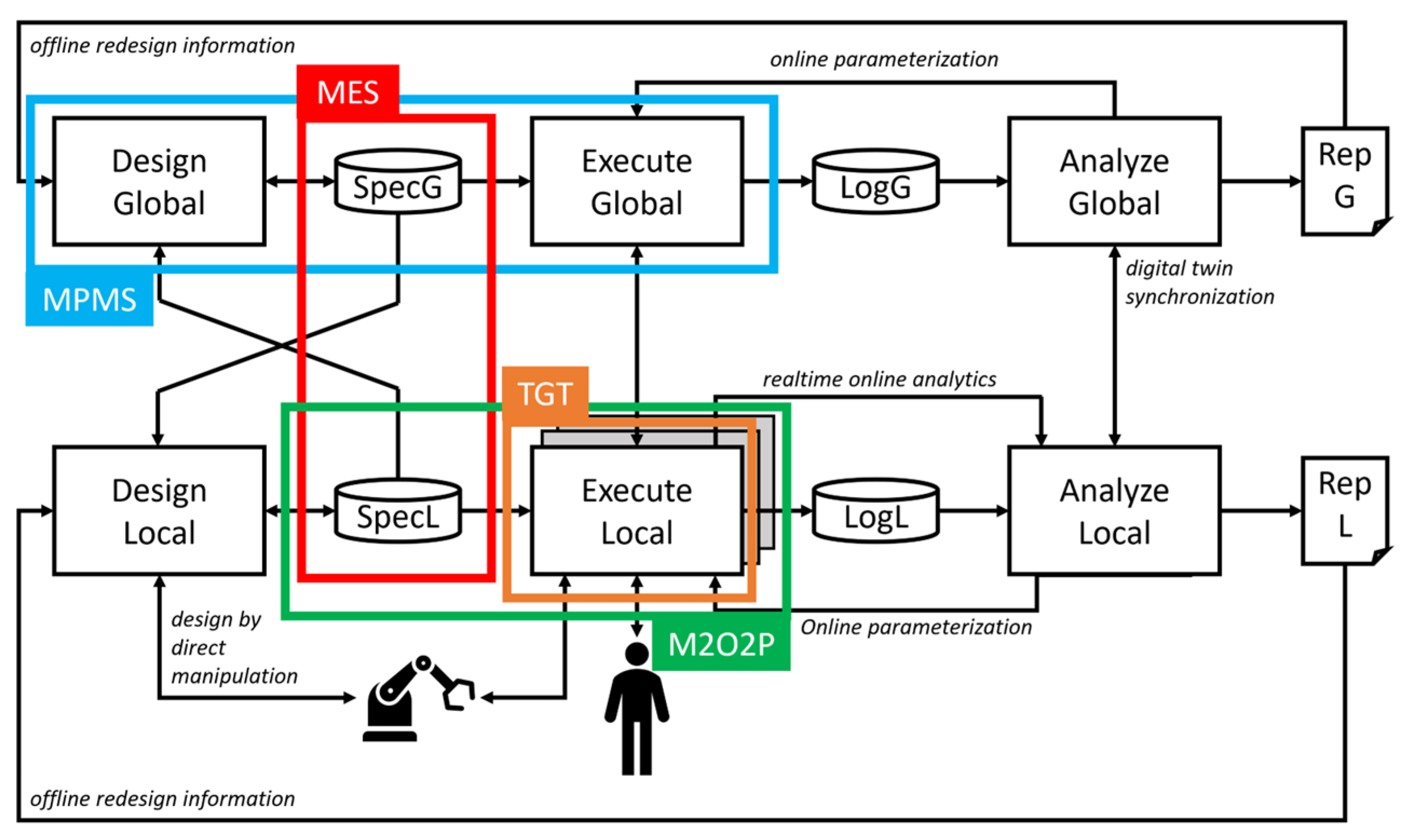
Thus, it consists of six main logical modules, whose interaction through interfaces are shown on the high-level logical software architecture [52] in Figure 1.
Each of the SHOP4CF components built within the project realizes a (sub)set of six main modules. Manufacturing scenarios which require specific functionalities are then addressed by an integrated set of components, whose interoperability is secured by the well-defined interfaces of the architecture and the data models.
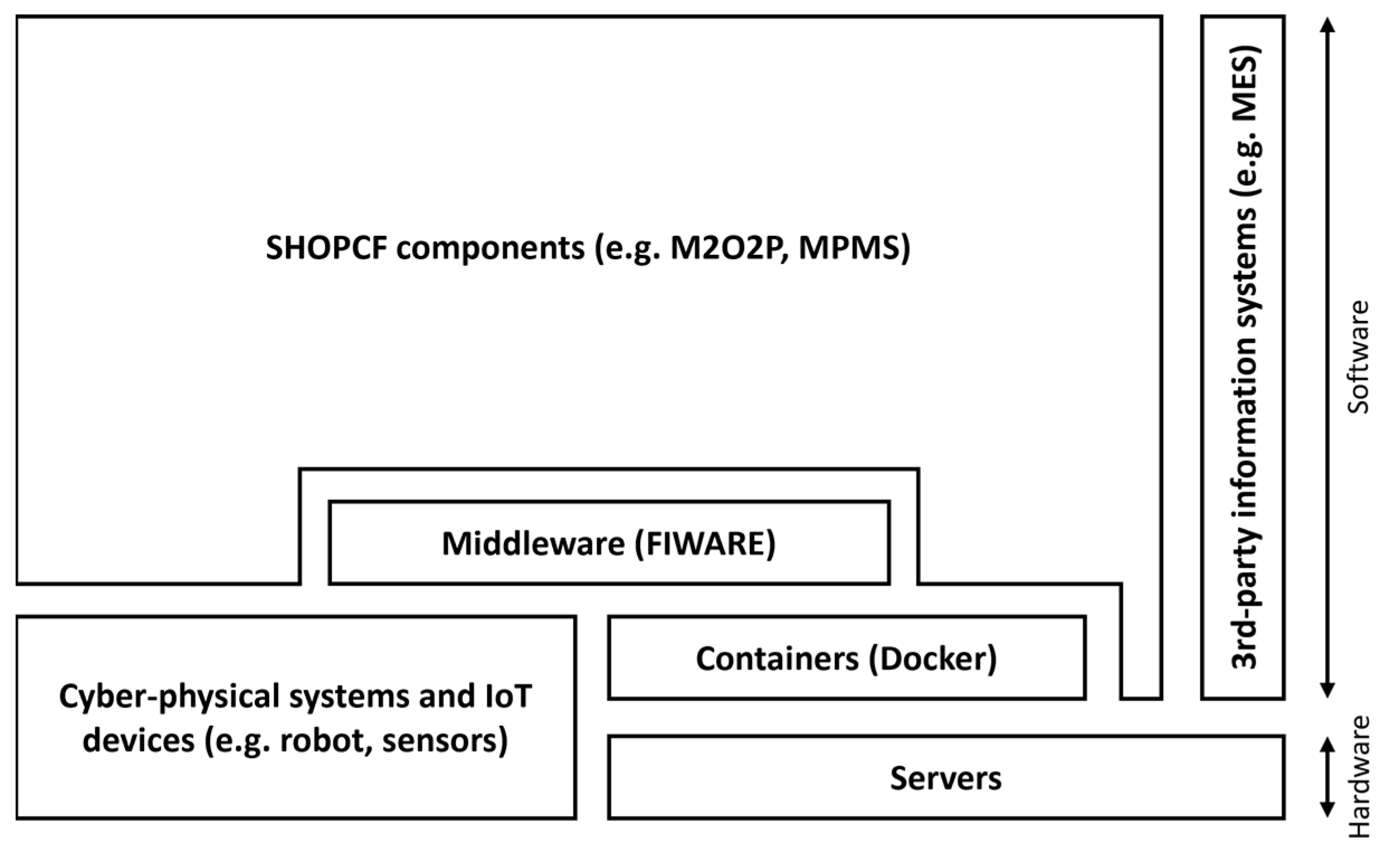
The platform aspect of the SHOP4CF architecture represents the organization, from the functional perspective, of software and hardware that is necessary for the software components to be operational. Its top-level logical view is illustrated in Figure 2.
The software layer consists of the SHOP4CF components, the middleware, containers (i.e., OS-level virtualization), and third-party information systems (i.e., external to SHOP4CF) that may exist on a shop floor. The hardware layer consists of servers. In addition, CPS and IoT devices on a shop floor may belong to both layers. Regarding the middleware, the chosen platform is FIWARE [53] due to its open-source capabilities and wide support from other European projects (https://www.fiware.org/about-us/impact-stories/, accessed on 15 June 2022). FIWARE uses the Orion Context Broker (OCB) to manage the whole lifecycle of context information through REST API (https://fiware-orion.readthedocs.io/en/master/, accessed on 4 August 2022), coupled with a Mongo database (https://www.mongodb.com/, accessed on 4 August 2022) to store the context information. In SHOP4CF, the OCB is enabled with Linked Data (LD) extensions, which means that it uses an NGSI-LD information model standardized by ETSI [54]. The FIWARE middleware is used whenever possible; only connections that have real-time constraints are organized directly between the two involved components (or between a component and an IoT) as the FIWARE middleware does not guarantee a response times for real-time systems [55].
With respect to data modeling, the focus is on the interoperability among components, i.e., the information exchanged between components, and not how a specific component translates and uses that information internally. By following the well-established formal approach by [56], data requirements are translated to concept data models, consisting of definitions of data entities, their attributes, and the relationships between the entities. Then, by applying technical constraints (i.e., concrete technical data format) and considering both the existing FIWARE data models and the IEC:62264-1 standard [22], specific SHOP4CF Data Models were defined (https://shop4cf.github.io/data-models/, accessed on 15 June 2022). The top-level logical data architecture is shown in Figure 3.
The data models are split according to the design–execution separation of concerns. Design data models refer to the definition of entities and typically are constant (or change infrequently). The design definition entities are Process Definition, Task Definition, Resource Specification, and Location. These describe the information during the design phase of manufacturing scenarios. For instance, a Process Definition includes the information of the sequence of tasks carried out during the process. Execution data models represent the information of the status of entities during execution. The execution entities are Process, Task, Resource, and Alert. The Process entity holds the information of a running process instance (according to its Process Definition). The Task entity describes a task that has been instantiated (according to its Task Definition). The information included in a Task entity is the set of resources performing the task, which specific materials are needed/used, where the task is executed, and what are the important parameters. The Resource entity describes the state of a resource, which can take the form of a: (i) device, according to [44], (ii) material, (iii) asset, i.e., a physical object that is neither a device nor a material, or (iv) person. The Alert entity holds the information of exceptional notifications, errors, and issues. Alerts are used for a notification of a malfunction, needed predictive maintenance, or some other state where an alert is needed, which triggers actions. An alert is not a recurrent information nor is it predictable.

3.2. M2O2P

The proposed HRI smart factory component, M2O2P, was developed, tested, and validated in a smart factory use case. The application was used to control a collaborative robot with a smart glove and with an interactive graphical user interface (GUI), hence presented here as a multimodal interface. Furthermore, the application was created to consider the human factors and provide a device agnostic interface in terms of the controlled device and the hand gesture recognition device. The important requirements for the component included a compatibility with FIWARE and the usage of the CaptoGlove LLC sensor glove (https://www.captoglove.com/, accessed on 7 June 2022).
Caiero-Rodriguez et al. [57] wrote a comprehensive comparison between commercial smart gloves, which includes CaptoGlove and provides information on how CaptoGlove compares to other commercially available products in the smart glove category. CaptoGlove is mainly designed for virtual reality (VR) applications and video games. Bringing such a glove to the industrial setup has its own limits and challenges.
The CaptoGlove has bending sensors in each finger, which limits the finger tracking degrees of freedom (DoF) to five. The receiver has a wired connection to each of the sensors and uses Bluetooth Low Energy (BLE) to connect to the PC. Additionally, the glove has pressure sensors on each fingertip. However, this functionality is not used in this application due to the repeatability problems when fingers are bent and pressure is applied to the sensor.
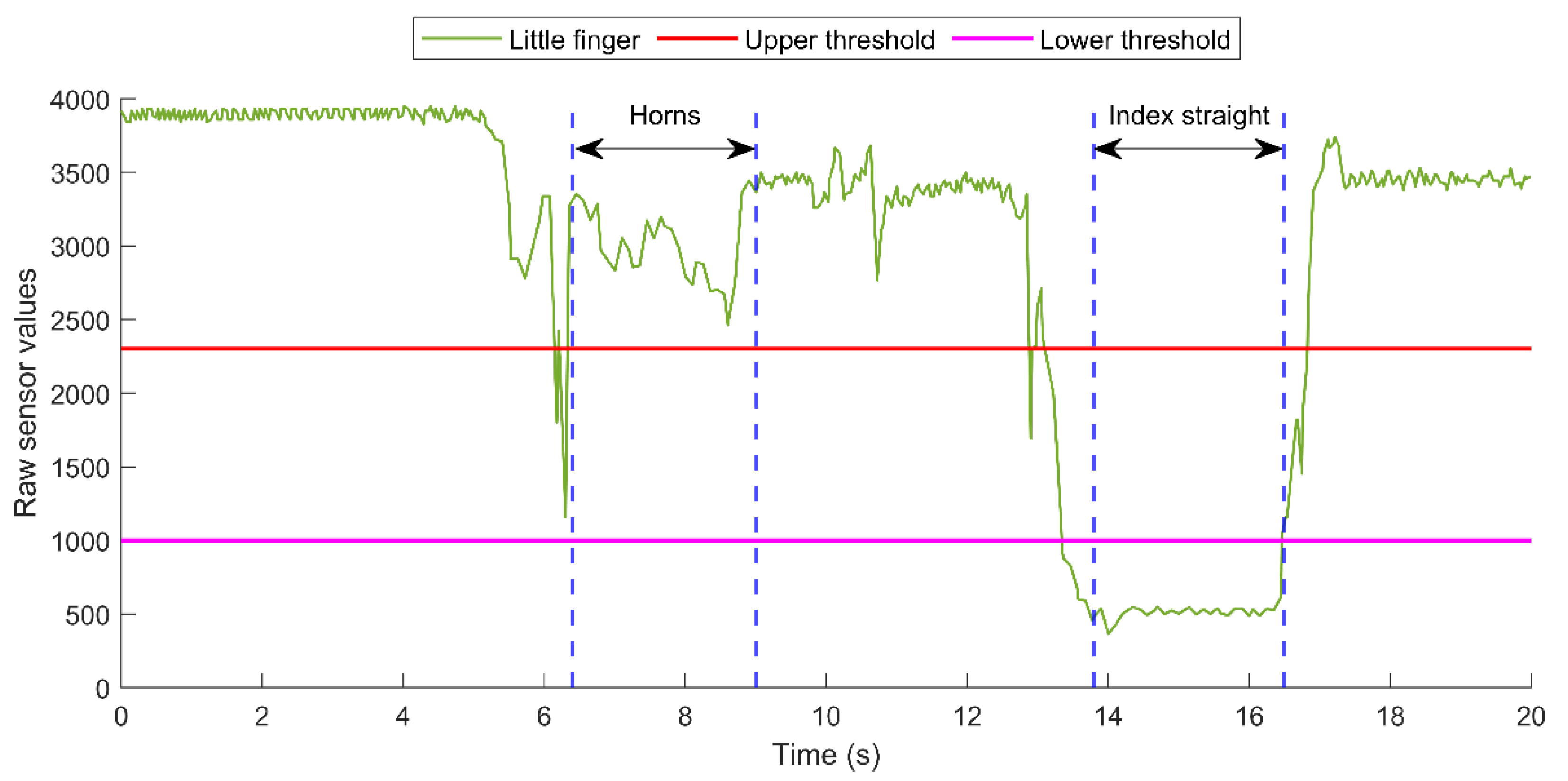
Bending sensors provide one raw sensor value per sensor, which is then processed by the component. Figure 4 presents how the sensor value of the little finger is changed when doing a gesture.
There are two example gestures made in the sequence of 20 s, Horns (the index and little finger is straight, the rest are bent) and Index straight (only the index finger is straight, the rest are bent), and the fingers are held straight otherwise. Such gestures lead the little finger to be straight during the Horns gesture and bent with the Index straight gesture. The sensor value for the little finger is presented in a green color and the time sequences where the gestures were recognized are illustrated with blue dashed lines. Each finger has three bending states, 0 when the sensor value is more than the red-colored upper threshold, 1 when the sensor value is between the thresholds, and 2 when the sensor value is less than the magenta-colored lower threshold.
M2O2P includes 21 different hand gestures for use. A list of these gestures with their corresponding names, the states of the fingers, and images are presented in Table 1.
The software of the CaptoGlove, Capto Suite, requires that the operating system (OS) be Windows 10. In addition, in the development phase, there were restrictions recognized for containerizing the CaptoGlove software development kit (SDK), which lead to the choice of deploying the SDK as Windows executable. The main function for the SDK is to connect to CaptoGlove via Bluetooth, to receive the sensor data from the glove, and to send the data via a TCP/IP connection to the other modules of the component.
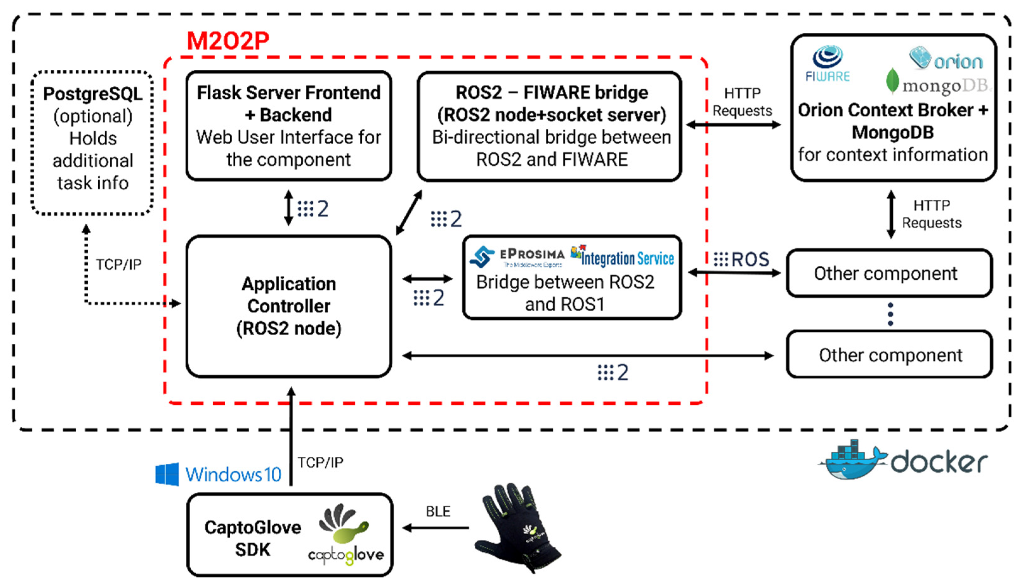
The simplified software architecture of the component Is displayed in Figure 5. M2O2P is presented inside the red dashed box and all the modules that are containerized with Docker are inside the black dashed box.
M2O2P consists of three main modules: the application controller (AC), Web user interface (Web UI), and ROS2-FIWARE bridge. The communication between the modules is done using ROS2 [58]. ROS is an open-source publish/subscribe system created to act as the middleware for robotic applications and is widely used [59]. ROS2 is a significant upgrade to ROS, providing additional new functionalities (https://github.com/ros2, accessed on 5 August 2022). Having ROS2, and with the help of the eProsima© Integration Service (https://integration-service.docs.eprosima.com/en/latest/#, accessed on 5 August 2022) ROS as interfaces, the application provides an option to directly control a robotic system that supports such interfaces on top of the FIWARE interface. The communication between FIWARE and ROS2 is established with a bi-directional ROS2-FIWARE bridge, which was created specifically for the use of M2O2P, yet was developed to be as configurable as possible. This module supports the LD information model and provides functionalities to handle the SHOP4CF data models through the REST API. As is explained in detail later in Section 4.3.2, most of the information exchanged between the different components is done with the Task entities. The information regarding the specification of the tasks is stored in a PostgreSQL DB (which realizes the SpecG/L data stores from the SHOP4CF architecture), which can be retrieved by the component as additional information. As the AC and Web UI are the more complex modules of the component, they are presented in further detail in the following subsections: Section 3.2.1 explains the functionalities of the AC and Section 3.2.2 elaborates the wireframe and functions of the Web UI.

3.2.1. Application Controller

The AC handles the processing of the raw sensor data to the states, gestures, and commands, and triggers the completion of the tasks invoked by the human operator. The main functions offered by the AC are as follows:
  • Establish a TCP/IP connection with the SDK;
  • Transform raw sensor data to states, gestures, and commands;
  • Receive tasks from FIWARE and, if necessary, retrieve additional task information from PostgreSQL (communication is explained in Section 4.3.2);
  • Provide additional options such as calibration, filtering by the task, and testing mode (these options are further elaborated in Section 3.2.2).
From the perspective of the gestural interface, the main function of the AC is the sensor data processing function, which is executed in a dedicated Python thread. The algorithm that is used for transforming the raw sensor data to the commands is presented in Algorithm 1 in pseudo code format. In a normal situation where the gesture made and held with the smart glove is correct, the application waits for 500 ms before prompting a notification to the user in the Web UI to further hold the gesture. If the same correct gesture is held for 1500 ms total, the task will be updated to a completed status. Such time ensures that the gesture is held long enough to be considered an intentional interaction and aims to filter the accidental gestures done when, for example, manipulating an object.
Algorithm 1: How Application Controller transforms raw sensor data to commands
Result: From raw sensor data to commands
while True do
if Message from any glove received then
  Retrieve sensor data, transform to states, recognize gesture;
   if Gesture is recognized then
    while Time is less than 1500ms do
     if Same gesture is held for 500ms then
      if Gesture = Gesture set by the task then
      print Hold gesture for a second to send the command;
      else
      print Doesn’t correspond gesture set by the task;
      break loop;
      end
     end
    Retrieve sensor data, transform to states, recognize gesture;
     if Gesture = Gesture set by the task AND gesture is held 1500ms then
     Update task entity status from “inProgress” to “completed”;
     Update Device entity command id;
     end
    end
   end
end
end
The AC is a class-based ROS2 node, which enables the changing states and modes invoked by the user with the Web UI in the background. Furthermore, the algorithm transforms the sensor data to the states and so on to gestures in the separate functions. By applying modifications to these functions and keeping the rest of the application as it is, the AC can handle any gesture recognition device as a source of input. Additionally, if there is an application and a device that can send similar data (one value per finger) to the AC via a TCP/IP connection, the change to another device would be possible by just changing the thresholds.

3.2.2. Web User Interface

The Web UI was developed for M2O2P to provide essential information for the user visually. As a smart factory component, the UI should utilize the help of the human operator when changes in configuration are necessary. Furthermore, the UI should take the human factors into consideration and present the information and options clearly.
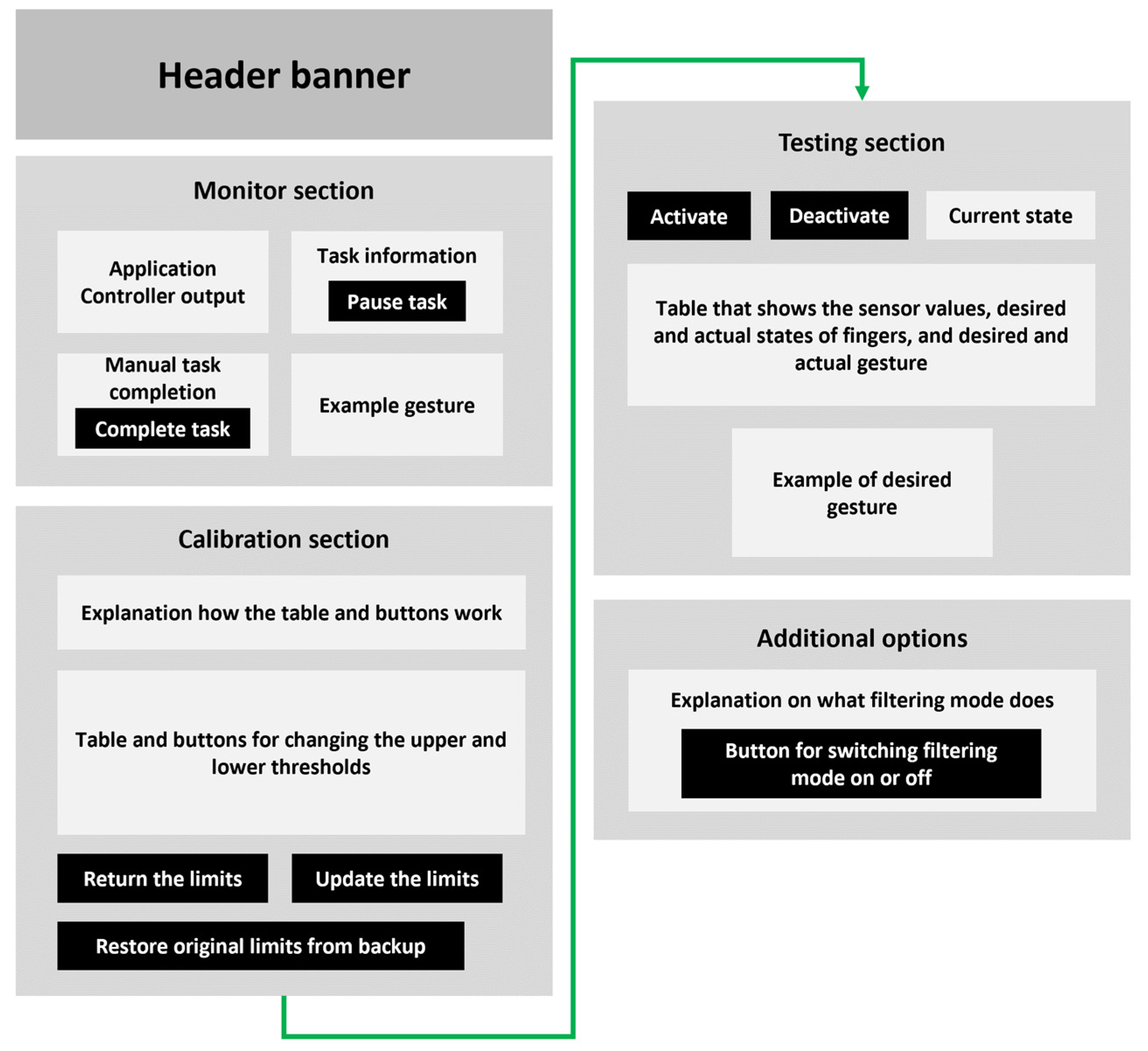
Figure 6 illustrates the wireframe of the UI, including all the different sections that are explained later. The black boxes in the wireframe represent the buttons. The UI includes only one page; hence, the continuation of the page is illustrated with a green arrow.
Since the primary use of the component is to receive tasks and complete them using the smart glove, the first section of the UI considers the task and AC monitoring. For the AC to be able to communicate with the user and give additional information, the application controller output module is reserved for this purpose. This acts as an outlet for the AC to guide the human worker and inform them about the functions occurring in the background. The Task information module holds the information about the received task, such as the task description and the name of the gesture required for completing the task and offers an option for the user to pause the task. This option is made for situations where the task is received but, for any reason, the human worker needs to take a break. The graphics interchange format (GIF) of the required gesture for completing the task is presented in the Example gesture module. If there is any situation where the gestures cannot be used to complete the task, the Manual task completion module can be used for such an action.
The calibration section was created to provide an easy way to redefine the sensor thresholds used during the application runtime. This section can be used when the application is setup for the first time, or if a calibration is needed for individual users. The calibration section used with the testing section provides a convenient tool for calibrating the glove for an efficient gesture recognition.
On top of being part of the calibration procedure, the testing section provides a way for the user to test the application. The section includes a desired gesture selection menu that can be used to train a specific gesture and additionally to see an example of all the possible gestures in the GIF format below the menu. When the testing mode is activated, the application will not allow a task completion through the gestures, which means that the testing mode can be used even during the ongoing process if, for instance, the application requires a runtime calibration.
Lastly, the Web UI offers the ability to change the Filtering mode. The Filtering mode determines if the commands sent forward are filtered by the tasks received from FIWARE, or if all the gestures that correspond to the commands are updated to FIWARE and to the ROS topics. The desired behavior in normal circumstances is to have the Filtering mode on since it ensures the reliability of the M2O2P.
The functionalities of the Web UI presented here follow the well-known design principles introduced in [60]; they provide feedback for the user by showing if the actions the user is doing are correct or not and create constraints for the user by not allowing the user to do actions in an incorrect sequence of the process. With only the glove as a communication modality, such information would not be provided for the user, and the user would not know what actions to perform. Furthermore, the UI includes the Manual task completion module, which is an alternative method for completing the task, hence the glove could not be used for such an interaction. From a design perspective, the need for the Web UI as a modality in such a gestural interface is thus evident.

4. Smart Factory Use Case

To test the functionalities of the M2O2P component, a use case from the Siemens pilot of the SHOP4CF project was identified. For the sake of the evaluation, this section explains how the multimodal interface has been used in the scenario. However, the component is independent from the use case, due to the adoption of the SHOP4CF architecture, and other application scenarios can be used. To describe the use case, the following structure is used. First, Section 4.1 introduces the use case description. Second, Section 4.2 presents the hardware set-up of the use case. Finally, Section 4.3 reports on the integrated solution consisting of explanations of the software components, the high-level architecture of the system, and the communication between the components.

4.1. Use Case Description and Envisioned Interaction

The parts that are used in an assembly process often come to the factories in boxes and are in scrambled poses. To make use of the parts, they need to be sorted. This problem can be solved by using robots to pick and sort the parts and is referred to as the bin-picking problem [61]. The bin-picking problem is a well-known challenge, and several commercial systems are available (e.g., Roboception™ rc_viscore and Keyence 3D Robot Vision). However, in this case the factory manager was complaining about the complexity of such systems. Therefore, following the principles of the human-centered design (HCD) [62], the factory manager was interviewed by the SHOP4CF partners to identify the major barriers they encountered during the process. During this analysis, it was identified that operators often need to move between different interfaces, whereby knowledge about different systems and interaction modalities was necessary (e.g., the robot UI and bin-picking UI), as also documented on [63]. Therefore, to simplify the process and help the operators, a technical solution composed of a multimodal interface for communicating with several systems was selected. The goal of using this interface is to reduce the amount of effort needed to learn the interfaces of different systems through the usage of a single, unique interface.
Based on these observations, the following interaction, as illustrated shown in Figure 7, was envisioned. For the sake of clarity, the interaction is described through the Business Process Model and Notation (BPMN) [64], which is a common language for manufacturing and business flows [65]. In the interaction, the human needs to act as the supervisor, which guides the robot to perform the scanning of the part.

4.2. Use Case Hardware

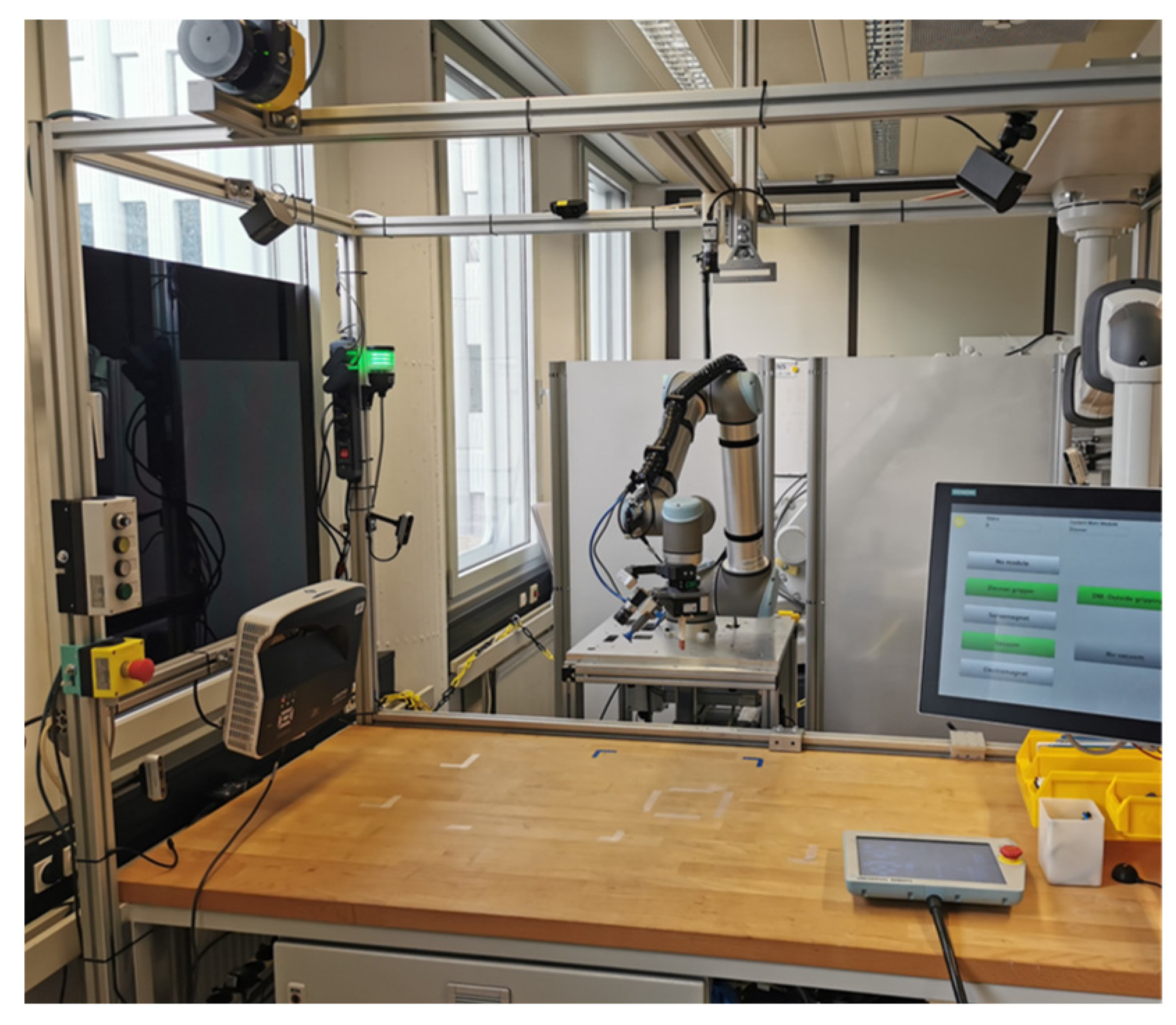
To study the effects of using a multimodal interface for the envisioned interaction, a robot cell was created. The robot cell compromised the hardware which was necessary to solve the application and guarantee a safe HRC. Therefore, a Universal Robot™ (UR) 10 with ISO 10218-1 certification [66] was used along with a Sick™ microScan3 safety scanner for limiting the robot speed when the operators were in the collaborative workspace. Next, a custom end effector with an embedded camera with the eye-in-hand configuration was mounted and a safe robot speed was selected by performing validation measurements with the selected end effector, as described by the authors in [67]. Finally, a Siemens SIMATIC™ HMI Unified Control Panel was added to enable the visualization of the Web UI. The robot cell can be seen in Figure 8.

4.3. Integrated Solution

M2O2P is not designed to work independently, since there is at least the need for the controlled device, and preferably for an orchestrator application that assigns the tasks for it. The smart factory use case is composed of such software components, and Section 4.3.1 introduces them and illustrates how they are mapped in the SHOP4CF architecture. Furthermore, Section 4.3.2 elaborates how the software components communicate with each other.

4.3.1. Components and Architecture

For the use case, two local level and one global level software components were employed. The components and their short explanations are presented in Table 2.
On top of the M2O2P component, MPMS [68] was used to handle the process orchestration and the trajectory generator (TGT) was utilized to communicate with the collaborative robot. Such components fulfil the requirements for the dependent applications of M2O2P.
The integrated solution consisting of a set of components was implemented according to the SHOP4CF architecture. Figure 9 maps the developed components onto the architecture. A manufacturing execution system (MES) creates the specification between the design and the execution in the global and local level. Such a specification could be, for example, storing information about the robot, as described in [69]. MPMS will handle the higher-level design and execution in the global level, and provides the task information to the local level, which is then handled by local level components, such as M2O2P and TGT.

4.3.2. Communication between Components

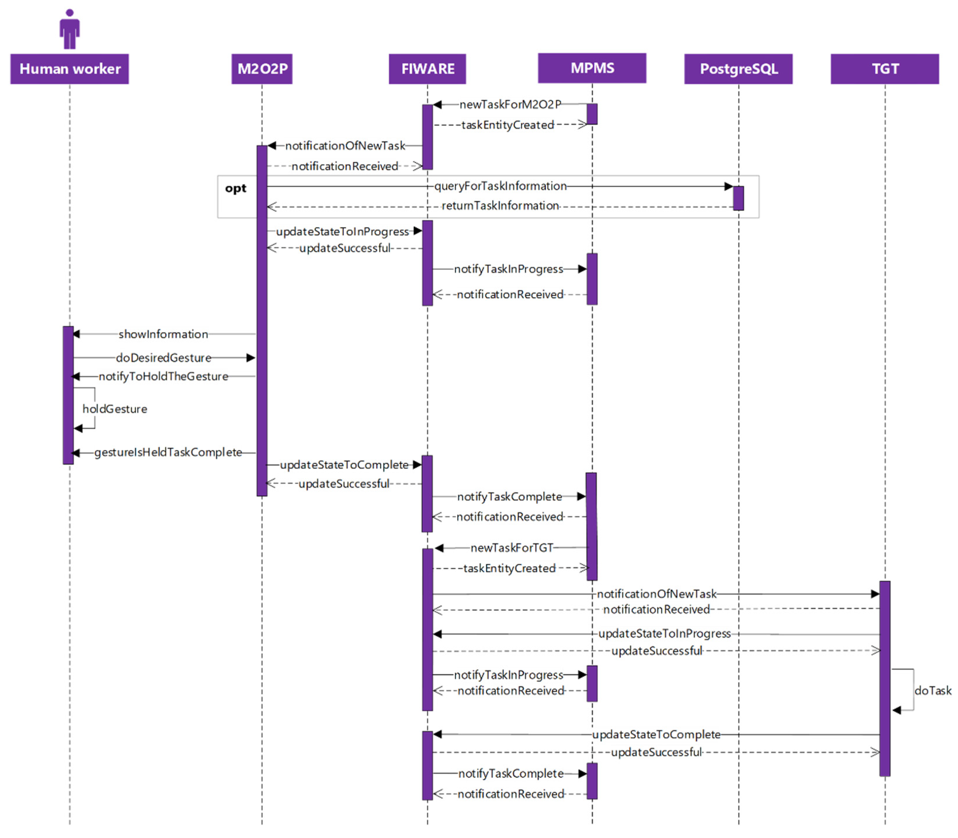
MPMS assigns tasks to either the human operator through the M2O2P component or to the robot through the TGT component. Tasks are represented as Task entities, following the SHOP4CF data model.
Figure 10 presents the sequence diagram of the information exchanged between the TGT, M2O2P, and MPMS through FIWARE. The main information exchange between both the local level components with MPMS is to receive a new task through FIWARE subscription notifications, update the task to an inProgress status, and update the task to a completed status after the task is finished. Additionally, M2O2P offers an option to provide additional information about the task through PostgreSQL. The option was added so that in more complex task specifications, the MPMS could provide some of the information in the PostgreSQL, from where the additional information would be queried. Such a functionality was not added to the TGT since the Task entity is sufficient enough to provide all the required information for the robot to operate.
The communication between M2O2P and the controlled application or device happens through the orchestrator, i.e., MPMS, hence it does not happen directly. Such a system design offers the functionality to control any FIWARE compatible device and provides a more universal solution.

5. Evaluation

The application was evaluated by testing the performance through user tests. To evaluate the component and its impact in the use case, the envisioned interaction described in Section 4.1 was selected for the design of the experiment. The goal of the experiment was to identify if the personalizing gestures are better perceived by the operators, therefore, a study with two subsequent interactions was envisioned. The scheme for the study is shown in Figure 11.
To investigate the effects of the gesture personalization on the human factors, the following measures were recorded during the test. At first, at time t1, the usability of the M2O2P and the Web UI were assessed using the SUS [70]. Afterwards, at time t2 and t3, the perceived workload in the interaction was gathered using the NASA TLX [71]. The interactions were randomized by having half of the participants experiencing personalized gestures first, and the other half predefined gestures first. Finally, at time t3, the users were asked if they preferred the personalized interaction or the predefined one.
The set of gestures used in the experiment were limited to seven to make the personalization procedure less complex. Moreover, these gestures were chosen according to their simplicity. One of the gestures was utilized only before t1 to not bias the users. Hence, the pool of available gestures in the personalization sequence was six for all participants. See the Supplementary Materials (File S1) for a list of the gestures.

6. Results and Discussion

The tests created for M2O2P aimed to evaluate the functionality, human factors, and gesture personalization. Section 6.1 introduces the test results of the evaluation in the user tests and additional information about the gesture recognition accuracy. Section 6.2 explains how the component compares to other similar applications.

6.1. Test Results

The tests to evaluate the M2O2P in the smart factory setting, the user tests, were executed with 10 participants with a low to medium level of engineering background, with a mean age of 31.05 years, and a standard deviation of 11.89. The tests were conducted according to the protocol outlined in Section 5. The testing was meant to identify the data to support our hypothesis, that personalization can reduce the workload of operators.
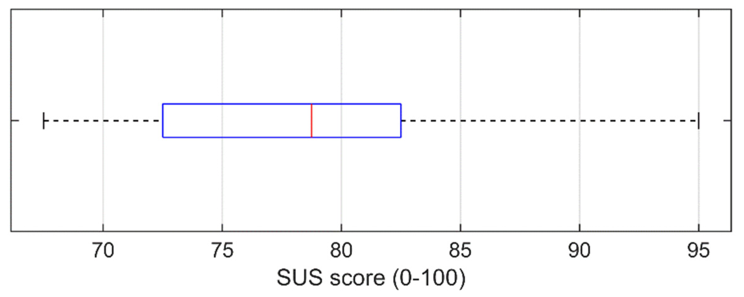
First, the results from the SUS of the overall system were analyzed; the scores are shown in Figure 12. The component obtained an A- grading, M = 79.25 SD = 8.34. To ensure that the score is acceptable by a wider user pool, Welch’s t-test was conducted after having checked the test preconditions. The t-test was used to compare the obtained results with the average score that the SUS usually obtains (M = 68), as suggested by [72]. The test yielded p < 0.05 (CI = 95%), therefore it is possible to consider the tool as a good interface for the greatest number of users.
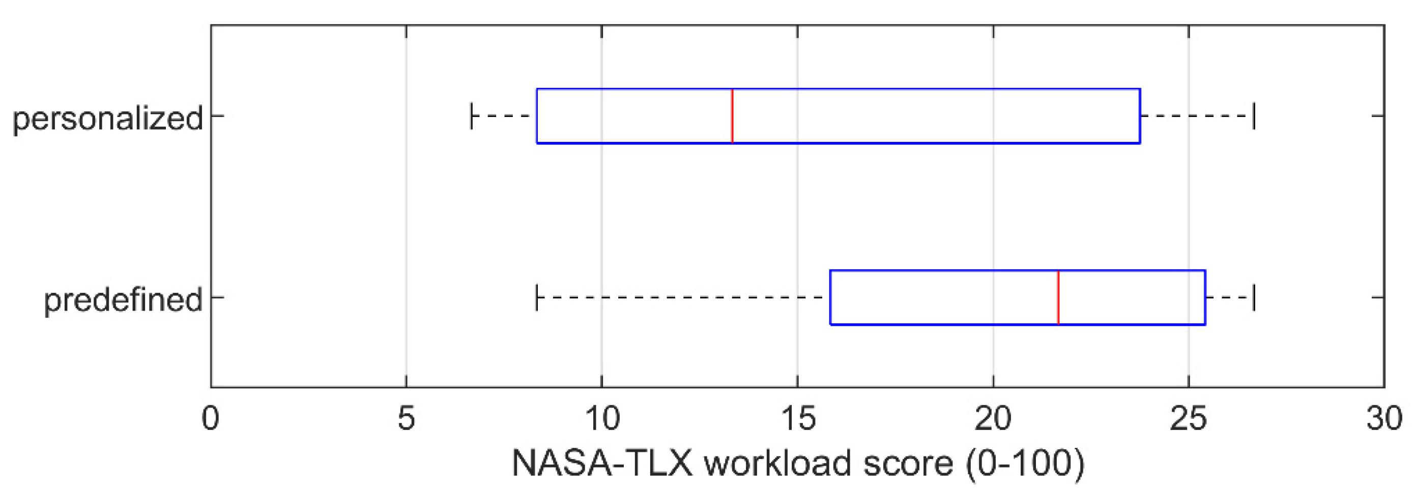
Second, the results from the NASA-TLX were examined to measure the differences across the two interactions. The results from the user test are shown in Figure 13.
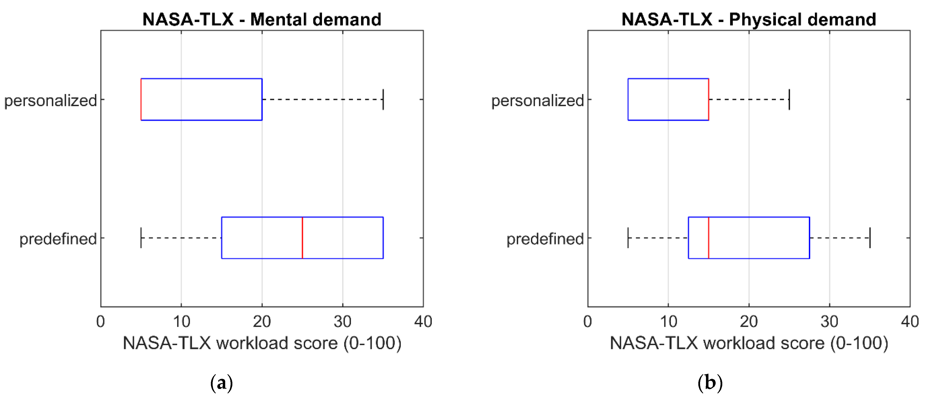
From the plot, it is possible to denote that there is a difference between the two interactions and the personalized interaction reported a lower average workload. Therefore, a Mann–Whitney U test was conducted since the normality assumption for the t-test was rejected p > 0.05 (CI = 95%). The test yielded p > 0.05 (CI = 95%), therefore a statistical significance between the two populations was not found and the hypothesis of a lower workload for the personalized interaction needs to be rejected. However, considering that the performed task was the same, an analysis of each of the NASA TLX factors was conducted. Such an analysis yielded that a statistical difference was found with the Mann–Whitney U test p < 0.05 (CI = 95%) on the measurements of mental and physical workload, as shown in Figure 14. Therefore, despite the test not showing that the overall workload was lower, a significant difference was found on the mental and physical levels and our hypothesis can be accepted with this limitation. Furthermore, the result suggests that the personalized gestures can be a good method to reduce those two strains on the operator. However, further investigations should be conducted to understand how this applies to other use cases.
Finally, in the last section, the users were asked if they liked being able to personalize the gestures and if they had to calibrate the glove. Nine out of the ten users preferred the interaction with the personalized gestures. Therefore, in gestural communication applications, the personalization option of the gestures should be considered when creating such solutions. Second, out of the 10 users, none had to perform a re-calibration, thus suggesting that a well-calibrated glove can work universally with multiple users. However, the tasks in the use case did not have much object manipulation, and therefore the thresholds can be calibrated to be looser than the tasks including an object manipulation. Therefore, even though no re-calibration was needed in this use case, it might be necessary in some other cases.
To further investigate the need for calibration, and simultaneously assess the gesture recognition accuracy provided by the M2O2P application, a stand-alone test case for the application was included. The test in question was conducted for the work done in [73], which also features the M2O2P as the main human–robot interface. The test was carried out with one participant to exclude the variability between the different users and ensure that the gestures are done correctly. Such a test evaluates the accuracy of the application, yet it does not provide information on how the accuracy would change for the individual users.
The test was done using the testing section of the Web UI. The user calibrated the glove prior the test and replicated all 21 gestures in 10 iterations, taking the glove off between every iteration. The test simulated a scenario where an individual user needs to take the glove off, for example, at the end of the workday, and continue using it in the next. The gesture in question was replicated, and when the user thought the gesture was correct, the UI was inspected to verify if the gesture was right or not. The results of the test are presented in Table 3.
For this test, there were two problematic gestures which were faced. In both cases, the user did the gesture, but it was not recognized before the gesture was slightly readjusted. Furthermore, in both problematic cases, the finger that needed readjustment was the ring finger, and the gesture was recognized right after the readjustment. The accuracy of the gesture recognition was as high as 99.05%, which is compared to similar applications in Section 6.2.
Since the M2O2P features a GUI, the human operator could see that the gesture was not recognized and could perform the readjustment. Moreover, since the ring finger was causing the problems in the recognition of the gestures, the problem could be fixed by recalibrating the upper threshold of the ring finger, leading to an improved recognition of the straight finger. The problems with the ring finger were not consistent, and therefore in the test scenario, the glove was not re-calibrated in between the iterations.

6.2. Comparison

To compare the developed application to other methods, research papers with similar objectives were reviewed. In [47], the authors did a comprehensive review about the gesture recognition methods and technologies for HRC, but solely focused on vision-based approaches. As referenced in the paper, two vision-based solutions and one survey focusing on vision-based technology were reviewed for the glove-based gesture section. None of them had researched the current possibilities of the glove-based input and mentioned the cumbersomeness and complex calibration and the setup of the glove. When comparing these two methods to each other and taking the perspective of cumbersomeness, it is justified to claim that wearing a glove is more cumbersome than not wearing one. In contrast to this, the vision-based gesture recognition system assumes that the gestures are done facing the camera, which can be cumbersome for the users or in some use cases. With a glove-based gesture recognition, this problem does not exist, and the gestures can be done anywhere on the shop floor if the connection can be maintained. Since glove-based methods read the gestures from the sensors and do not need to interpret the RGB/depth data before acquiring the information, they offer also a significantly less computationally demanding solution. Some of the glove-based applications can be complex to calibrate. However, the calibration of the application depends on how the sensor values are interpreted and processed, and therefore it is not universally true that all glove-based applications are complex to calibrate. The reported test results of this paper show that calibration was not needed for individual users.
In [74], authors proposed a gesture recognition method based on the neural network, where 10 hand gestures are recorded by Kinect v2, augmented, and trained with the neural network. The accuracy of the neural network was as high as 98.9%, but the system requires that the user knows the gestures previously, and the gestures were recorded by one individual, which might not guarantee that the system works with any hand.
In [75], the authors proposed an ML-based gesture recognition system that handles static and dynamic gestures acquired from the IMU sensors worn by the human operator. The operator wears five IMU sensors, two per each hand and one on the chest to recognize the pose of the corresponding joint. Additionally, the human wears an ultra-wideband (UWB) tag to track the position in the room. The method provides a high accuracy of 98%. In a similar system in [76], the developed application uses an RGBD camera to recognize dynamic hand gestures, such as letters and numbers, which are interpreted as gestures. The average accuracy of the recognition system depending on illumination was relatively high at 92%. The first dynamic gesture recognition system requires the human operator to wear multiple sensors on different places on the body and can be cumbersome. Additionally, in both solutions, the gestures require a somewhat large movement of the arms, which can negatively affect the process flow.
In all the aforementioned solutions, the accuracy was lower than in the proposed application. However, in those solutions the accuracy was measured either with a test set of images or with multiple users, whereas the gesture recognition accuracy of M2O2P was measured with one participant, hence the measured accuracy cannot be compared to such solutions on a one-to-one basis. The intended use of the application is to have the application calibrated for the user so that the accuracy of the measurement remains high. When such an interaction method is proposed for the user, the application must work with a high precision. A less accurate interaction method would lead to user frustration and users would prefer more reliable input methods. Furthermore, there were no personalization options provided by the applications, which by the results of this paper presents as an option which should be considered in gesture interfaces.

7. Conclusions

In this paper, we proposed a multi-modal interface for a natural input. The proposed solution, M2O2P, provides a gestural interface for a human to communicate with other systems using a smart glove. Since the sensor technology is expected to advance, the M2O2P was designed to support the changing of the gesture recognition device. The component reads the smart glove device, interprets the sensor values as states, gestures, and, ultimately, as commands. The used algorithm for the gesture detection uses first order logic with a predefined multi gesture set. This algorithm can be improved in future research by adapting AI and ML techniques.
Furthermore, the solution provides a GUI for a more complete user experience by providing essential information to the user, such as task description and an example of the required gesture in GIF format, and functionalities such as calibration, testing, and changing of the filtering mode of the application. Through the defined filtering mode, the component can be utilized for completing tasks or for giving predefined commands for a controlled device, such as a robot. M2O2P was developed to be a smart factory component that has capabilities to be context-aware and be modularly integrated with other systems.
The accuracy of M2O2P was measured to be 99.05%, which is similar to what other gesture recognition systems have reported. However, the evaluation of the accuracy was done focusing on the accuracy of the application itself and with one participant and thus do not provide a definite insight on how the glove would perform for individual users. Furthermore, the M2O2P interface with personalized gestures showed a non-statistical significance in the difference of the workload when compared to the predefined gestures. However, this was found more related to the task rather than the interface, since the physical and mental levels of the workload were found to be statistically lower with the personalized gestures. Therefore, future studies should concentrate on integrating personalization for ensuring that the mental and physical strain are the lowest. Additionally, proper care should be taken in the overall design of the task when personalized gestures are used. Finally, the results of the user study should be considered in the context of the user population. Therefore, further studies with different populations might be needed to further define the generalizations of the proposed methods.

Supplementary Materials

The following supporting information can be downloaded at: https://www.mdpi.com/article/10.3390/machines10100957/s1, File S1: Gestures list.

Author Contributions

Conceptualization, S.R. and M.P.; methodology, S.R. and M.P.; software, S.R., M.P., and K.T.; validation, S.R., M.P., and S.A.; formal analysis, S.R. and M.P.; investigation, S.R.; resources, S.R., M.P., and K.T.; data curation, S.R. and M.P.; writing—original draft preparation and S.R., M.P., and K.T.; writing—review and editing, S.R., M.P., K.T., S.A., J.S., and W.M.M.; visualization, S.R.; supervision, S.A. and J.L.M.L.; project administration, S.A. and J.L.M.L.; funding acquisition, J.L.M.L. All authors have read and agreed to the published version of the manuscript.

Funding

This research has received funding from the European Union’s Horizon 2020 research and innovation program under grant agreement No 873087. The results obtained in this work reflect only the authors’ views and not those of the European Commission; the Commission is not responsible for any use that may be made of the information they contain.

Institutional Review Board Statement

Ethical review and approval were waived for this study due to anonymized data collection which, in Bavaria, does not need approval from an ethical committee (https://ethikkommission.blaek.de/studien/sonstige-studien/antragsunterlagen-ek-primarberatend-15-bo) (accessed on 10 August 2022).

Informed Consent Statement

Informed consent was obtained from all subjects involved in the study.

Data Availability Statement

The original contributions presented in the study are included in the article/Supplementary Materials; further inquiries can be directed to the corresponding author.

Acknowledgments

The authors would like to thank the users who took part in the study.

Conflicts of Interest

The authors declare no conflict of interest.

References

  1. Suzić, N.; Forza, C.; Trentin, A.; Anišić, Z. Implementation guidelines for mass customization: Current characteristics and suggestions for improvement. Prod. Plan. Control 2018, 29, 856–871. [Google Scholar] [CrossRef]
  2. Lasi, H.; Fettke, P.; Kemper, H.-G.; Feld, T.; Hoffmann, M. Industry 4.0. Bus. Inf. Syst. Eng. 2014, 6, 239–242. [Google Scholar] [CrossRef]
  3. Barbazza, L.; Faccio, M.; Oscari, F.; Rosati, G. Agility in assembly systems: A comparison model. Assem. Autom. 2017, 37, 411–421. [Google Scholar] [CrossRef]
  4. Krämer, N.C.; von der Pütten, A.; Eimler, S. Human-Agent and Human-Robot Interaction Theory: Similarities to and Differences from Human-Human Interaction. In Human-Computer Interaction: The Agency Perspective; Zacarias, M., de Oliveira, J.V., Eds.; Springer: Berlin/Heidelberg, Germany, 2012; Volume 396, pp. 215–240. [Google Scholar] [CrossRef]
  5. Goodrich, M.A.; Schultz, A.C. Human-Robot Interaction: A Survey. Found. Trends® Hum.–Comput. Interact. 2007, 1, 203–275. [Google Scholar] [CrossRef]
  6. Prati, E.; Peruzzini, M.; Pellicciari, M.; Raffaeli, R. How to include User Experience in the design of Human-Robot Interaction. Robot. Comput.-Integr. Manuf. 2021, 68, 102072. [Google Scholar] [CrossRef]
  7. Benyon, D. Designing User Experience, 4th ed.; Pearson Education Limited: Harlow, UK, 2017. [Google Scholar]
  8. Miller, L.; Kraus, J.; Babel, F.; Baumann, M. More Than a Feeling—Interrelation of Trust Layers in Human-Robot Interaction and the Role of User Dispositions and State Anxiety. Front. Psychol. 2021, 12, 592711. [Google Scholar] [CrossRef]
  9. Nandi, A.; Jiang, L.; Mandel, M. Gestural query specification. Proc. VLDB Endow. 2013, 7, 289–300. [Google Scholar] [CrossRef] [Green Version]
  10. Liu, J.; Zhong, L.; Wickramasuriya, J.; Vasudevan, V. uWave: Accelerometer-based personalized gesture recognition and its applications. Pervasive Mob. Comput. 2009, 5, 657–675. [Google Scholar] [CrossRef]
  11. Kotzé, P.; Marsden, G.; Lindgaard, G.; Wesson, J.; Winckler, M. (Eds.) Human-Computer Interaction—INTERACT 2013. In Proceedings of the 14th IFIP TC 13 International Conference, Cape Town, South Africa, 2–6 September 2013; Springer: Berlin/Heidelberg, Germany, 2013; Volume 8118. [Google Scholar] [CrossRef]
  12. Sylari, A.; Ferrer, B.R.; Lastra, J.L.M. Hand Gesture-Based On-Line Programming of Industrial Robot Manipulators. In Proceedings of the 2019 IEEE 17th International Conference on Industrial Informatics (INDIN), Helsinki, Finland, 23–25 July 2019; pp. 827–834. [Google Scholar] [CrossRef]
  13. Weiser, M. The Computer for the 21st Century. Sci. Am. 1991, 265, 8. [Google Scholar] [CrossRef]
  14. Hozdić, E. Smart Factory for Industry 4.0: A Review. Int. J. Mod. Manuf. Technol. 2015, 7, 28–35. [Google Scholar]
  15. Shi, Z.; Xie, Y.; Xue, W.; Chen, Y.; Fu, L.; Xu, X. Smart factory in Industry 4.0. Syst. Res. Behav. Sci. 2020, 37, 607–617. [Google Scholar] [CrossRef]
  16. Lucke, D.; Constantinescu, C.; Westkämper, E. Smart Factory—A Step towards the Next Generation of Manufacturing. In Manufacturing Systems and Technologies for the New Frontier; Mitsuishi, M., Ueda, K., Kimura, F., Eds.; Springer: London, UK, 2008; pp. 115–118. [Google Scholar] [CrossRef]
  17. Jazdi, N. Cyber physical systems in the context of Industry 4.0. In Proceedings of the 2014 IEEE International Conference on Automation, Quality and Testing, Robotics, Cluj-Napoca, Romania, 22–24 May 2014; pp. 14–16. [Google Scholar] [CrossRef]
  18. Mohammed, W.M.; Ferrer, B.R.; Iarovyi, S.; Negri, E.; Fumagalli, L.; Lobov, A.; Lastra, J.L.M. Generic platform for manufacturing execution system functions in knowledge-driven manufacturing systems. Int. J. Comput. Integr. Manuf. 2018, 31, 262–274. [Google Scholar] [CrossRef]
  19. Castano, F.; Haber, R.E.; Mohammed, W.M.; Nejman, M.; Villalonga, A.; Lastra, J.L.M. Quality monitoring of complex manufacturing systems on the basis of model driven approach. Smart Struct. Syst. 2020, 26, 495–506. [Google Scholar] [CrossRef]
  20. Lee, E.A. Cyber Physical Systems: Design Challenges. In Proceedings of the 11th IEEE International Symposium on Object and Component-Oriented Real-Time Distributed Computing (ISORC), Orlando, FL, USA, 5–7 May 2008; pp. 363–369. [Google Scholar] [CrossRef] [Green Version]
  21. Kusiak, A. Smart manufacturing. Int. J. Prod. Res. 2017, 56, 508–517. [Google Scholar] [CrossRef]
  22. IEC 62264 (5-2013); Enterprise-Control System Integration. nternational Electrotechnical Commission: London, UK, 22 May 2013.
  23. Bettenhausen, K.D.; Kowalewski, S. Cyber-Physical Systems: Chancen und Nutzen Aus Sicht der Automation. In VDI/VDE-Gesellschaft Mess-und Automatisierungstechnik; VDI: Düsseldorf, Germany, 2013; Available online: https://www.vdi.de/ueber-uns/presse/publikationen/details/cyber-physical-systems-chancen-und-nutzen-aus-sicht-der-automation (accessed on 12 July 2022).
  24. Wang, S.; Zhang, C.; Liu, C.; Li, D.; Tang, H. Cloud-assisted interaction and negotiation of industrial robots for the smart factory. Comput. Electr. Eng. 2017, 63, 66–78. [Google Scholar] [CrossRef]
  25. Torn, I.; Vaneker, T. Mass Personalization with Industry 4.0 by SMEs: A concept for collaborative networks. Procedia Manuf. 2019, 28, 135–141. [Google Scholar] [CrossRef]
  26. Kolbeinsson, A.; Lagerstedt, E.; Lindblom, J. Foundation for a classification of collaboration levels for human-robot cooperation in manufacturing. Prod. Manuf. Res. 2019, 7, 448–471. [Google Scholar] [CrossRef] [Green Version]
  27. Sheridan, T.B. Human–Robot Interaction: Status and Challenges. Hum. Factors J. Hum. Factors Ergon. Soc. 2016, 58, 525–532. [Google Scholar] [CrossRef]
  28. McColl, D.; Nejat, G. Affect detection from body language during social HRI. In Proceedings of the 2012 IEEE RO-MAN: The 21st IEEE International Symposium on Robot and Human Interactive Communication, Paris, France, 9–13 September 2012; pp. 1013–1018. [Google Scholar] [CrossRef]
  29. Hormaza, L.A.; Mohammed, W.M.; Ferrer, B.R.; Bejarano, R.; Lastra, J.L.M. On-line Training and Monitoring of Robot Tasks through Virtual Reality. In Proceedings of the 2019 IEEE 17th International Conference on Industrial Informatics (INDIN), Helsinki, Finland, 22–25 July 2019; pp. 841–846. [Google Scholar] [CrossRef]
  30. Lazaro, O.D.M.; Mohammed, W.M.; Ferrer, B.R.; Bejarano, R.; Lastra, J.L.M. An Approach for adapting a Cobot Workstation to Human Operator within a Deep Learning Camera. In Proceedings of the 2019 IEEE 17th International Conference on Industrial Informatics (INDIN), Helsinki, Finland, 22–25 July 2019; pp. 789–794. [Google Scholar] [CrossRef]
  31. Lackey, S.; Barber, D.; Reinerman, L.; Badler, N.I.; Hudson, I. Defining Next-Generation Multi-Modal Communication in Human Robot Interaction. In Proceedings of the Human Factors and Ergonomics Society Annual Meeting, Atlanta, GA, USA, 23 September 2011; SAGE Publications: Los Angeles, CA, USA, 2011; Volume 55, pp. 461–464. [Google Scholar] [CrossRef]
  32. Li, S.; Zhang, X. Implicit Intention Communication in Human–Robot Interaction Through Visual Behavior Studies. IEEE Trans. Human-Machine Syst. 2017, 47, 437–448. [Google Scholar] [CrossRef]
  33. Jones, A.D.; Watzlawick, P.; Bevin, J.H.; Jackson, D.D. Pragmatics of Human Communication: A Study of Interactional Patterns, Pathologies, and Paradoxes; Norton: New York, NY, USA, 1980. [Google Scholar] [CrossRef]
  34. Denkowski, M.; Dmitruk, K.; Sadkowski, L. Building Automation Control System driven by Gestures. In IFAC-PapersOnLine; Elsevier: Amsterdam, The Netherlands, 2015; Volume 48, pp. 246–251. [Google Scholar] [CrossRef]
  35. Jamone, L.; Natale, L.; Metta, G.; Sandini, G. Highly Sensitive Soft Tactile Sensors for an Anthropomorphic Robotic Hand. IEEE Sens. J. 2015, 15, 4226–4233. [Google Scholar] [CrossRef]
  36. Yuan, W.; Dong, S.; Adelson, E.H. GelSight: High-Resolution Robot Tactile Sensors for Estimating Geometry and Force. Sensors 2017, 17, 2762. [Google Scholar] [CrossRef] [PubMed] [Green Version]
  37. Chi, C.; Sun, X.; Xue, N.; Li, T.; Liu, C. Recent Progress in Technologies for Tactile Sensors. Sensors 2018, 18, 948. [Google Scholar] [CrossRef] [PubMed] [Green Version]
  38. Schmitz, A.; Maiolino, P.; Maggiali, M.; Natale, L.; Cannata, G.; Metta, G. Methods and Technologies for the Implementation of Large-Scale Robot Tactile Sensors. IEEE Trans. Robot. 2011, 27, 389–400. [Google Scholar] [CrossRef]
  39. Hinton, G.; Deng, L.; Yu, D.; Dahl, G.E.; Mohamed, A.-R.; Jaitly, N.; Senior, A.; Vanhoucke, V.; Nguyen, P.; Sainath, T.N.; et al. Deep Neural Networks for Acoustic Modeling in Speech Recognition: The Shared Views of Four Research Groups. IEEE Signal Process. Mag. 2012, 29, 82–97. [Google Scholar] [CrossRef]
  40. Bingol, M.C.; Aydogmus, O. Performing predefined tasks using the human–robot interaction on speech recognition for an industrial robot. Eng. Appl. Artif. Intell. 2020, 95, 103903. [Google Scholar] [CrossRef]
  41. Coronado, E.; Villalobos, J.; Bruno, B.; Mastrogiovanni, F. Gesture-based robot control: Design challenges and evaluation with humans. In Proceedings of the 2017 IEEE International Conference on Robotics and Automation (ICRA), Singapore, 29 May–3 June 2017; pp. 2761–2767. [Google Scholar] [CrossRef]
  42. Guo, L.; Lu, Z.; Yao, L. Human-Machine Interaction Sensing Technology Based on Hand Gesture Recognition: A Review. IEEE Trans. Human-Machine Syst. 2021, 51, 300–309. [Google Scholar] [CrossRef]
  43. Shen, Z.; Yi, J.; Li, X.; Mark, L.H.P.; Hu, Y.; Wang, Z. A soft stretchable bending sensor and data glove applications. In Proceedings of the 2016 IEEE International Conference on Real-Time Computing and Robotics (RCAR), Angkor Wat, Cambodia, 6–10 June 2016; pp. 88–93. [Google Scholar] [CrossRef] [Green Version]
  44. Lin, B.-S.; Lee, I.-J.; Yang, S.-Y.; Lo, Y.-C.; Lee, J.; Chen, J.-L. Design of an Inertial-Sensor-Based Data Glove for Hand Function Evaluation. Sensors 2018, 18, 1545. [Google Scholar] [CrossRef]
  45. Jones, C.L.; Wang, F.; Morrison, R.; Sarkar, N.; Kamper, D.G. Design and Development of the Cable Actuated Finger Exoskeleton for Hand Rehabilitation Following Stroke. IEEE/ASME Trans. Mechatron. 2012, 19, 131–140. [Google Scholar] [CrossRef]
  46. Wen, R.; Tay, W.-L.; Nguyen, B.P.; Chng, C.-B.; Chui, C.-K. Hand gesture guided robot-assisted surgery based on a direct augmented reality interface. Comput. Methods Programs Biomed. 2014, 116, 68–80. [Google Scholar] [CrossRef]
  47. Liu, H.; Wang, L. Gesture recognition for human-robot collaboration: A review. Int. J. Ind. Ergon. 2018, 68, 355–367. [Google Scholar] [CrossRef]
  48. Pisharady, P.; Saerbeck, M. Recent methods and databases in vision-based hand gesture recognition: A review. Comput. Vis. Image Underst. 2015, 141, 152–165. [Google Scholar] [CrossRef]
  49. Cohen, P.R. The role of natural language in a multimodal interface. In Proceedings of the 5th Annual ACM Symposium on User interface Software and Technology—UIST’ 92, Monteray, CA, USA, 15–18 November 1992; pp. 143–149. [Google Scholar] [CrossRef]
  50. Maurtua, I.; Fernández, I.; Tellaeche, A.; Kildal, J.; Susperregi, L.; Ibarguren, A.; Sierra, B. Natural multimodal communication for human–robot collaboration. Int. J. Adv. Robot. Syst. 2017, 14, 172988141771604. [Google Scholar] [CrossRef] [Green Version]
  51. Grefen, P.W.P.J.; Boultadakis, G. Designing an Integrated System for Smart Industry: The Development of the HORSE Architecture; Independently Published: Traverse City, MI, USA, 2021. [Google Scholar]
  52. Zimniewicz, M. Deliverable 3.2—SHOP4CF Architecture. 2020; p. 26. Available online: https://live-shop4cf.pantheonsite.io/wp-content/uploads/2021/07/SHOP4CF-WP3-D32-DEL-210119-v1.0.pdf (accessed on 8 August 2022).
  53. Cirillo, F.; Solmaz, G.; Berz, E.L.; Bauer, M.; Cheng, B.; Kovacs, E. A Standard-Based Open Source IoT Platform: FIWARE. IEEE Internet Things Mag. 2019, 2, 12–18. [Google Scholar] [CrossRef]
  54. ETSI GS CIM 009 V1.1.1 (2019-01); Context Information Management (CIM) NGSI-LD API. ETSI: Sophia Antipolis Cedex, France, 2019.
  55. Araujo, V.; Mitra, K.; Saguna, S.; Åhlund, C. Performance evaluation of FIWARE: A cloud-based IoT platform for smart cities. J. Parallel Distrib. Comput. 2019, 132, 250–261. [Google Scholar] [CrossRef]
  56. West, M. Developing High Quality Data Models; Morgan Kaufmann: Burlington, MA, USA, 2011. [Google Scholar] [CrossRef]
  57. Caeiro-Rodríguez, M.; Otero-González, I.; Mikic-Fonte, F.; Llamas-Nistal, M. A Systematic Review of Commercial Smart Gloves: Current Status and Applications. Sensors 2021, 21, 2667. [Google Scholar] [CrossRef] [PubMed]
  58. Macenski, S.; Foote, T.; Gerkey, B.; Lalancette, C.; Woodall, W. Robot Operating System 2: Design, architecture, and uses in the wild. Sci. Robot. 2022, 7, eabm6074. [Google Scholar] [CrossRef]
  59. Maruyama, Y.; Kato, S.; Azumi, T. Exploring the performance of ROS2. In Proceedings of the 13th International Conference on Embedded Software, Pittsburgh, PA, USA, 1–7 October 2016; pp. 1–10. [Google Scholar] [CrossRef] [Green Version]
  60. Norman, D. The Design of Everyday Things; Currency Doubleday: New York, NY, USA, 2013; ISBN 0-465-07299-2. [Google Scholar]
  61. Buchholz, D. Bin-Picking; Springer International Publishing: Cham, Switzerland, 2016; Volume 44. [Google Scholar] [CrossRef]
  62. ISO 9241:112 (2017); Ergonomics of Human-System Interaction—Part 112: Principles for the Presentation of Information: Ergonomics of Human-System Interaction, 1st ed. International Organization for Standardization: Geneva, Switzerland, 2017.
  63. Bouklis, P.; Garbi, A. Deliverable 5.1—Definition of the Deployment Scenarios; 2020; p. 49. Available online: https://live-shop4cf.pantheonsite.io/wp-content/uploads/2021/07/SHOP4CF-WP5-D51-DEL-201215-v1.0.pdf (accessed on 8 August 2022).
  64. OMG. Business Process Model and Notation (BPMN), Version 2.0; 2013. Available online: http://www.omg.org/spec/BPMN/2.0.2 (accessed on 8 July 2022).
  65. Prades, L.; Romero, F.; Estruch, A.; García-Dominguez, A.; Serrano, J. Defining a Methodology to Design and Implement Business Process Models in BPMN According to the Standard ANSI/ISA-95 in a Manufacturing Enterprise. Procedia Eng. 2013, 63, 115–122. [Google Scholar] [CrossRef] [Green Version]
  66. ISO 10218-1:2011; Robots and robotic devices—Safety requirements for industrial robots—Part 1: Robots, 2nd ed. International Organization for Standarization: Geneva, Switzerland, 2011.
  67. Pantano, M.; Blumberg, A.; Regulin, D.; Hauser, T.; Saenz, J.; Lee, D. Design of a Collaborative Modular End Effector Considering Human Values and Safety Requirements for Industrial Use Cases. In Human-Friendly Robotics 2021; Palli, G., Melchiorri, C., Meattini, R., Eds.; Springer International Publishing: Cham, Switzerland, 2022; Volume 23, pp. 45–60. [Google Scholar] [CrossRef]
  68. Vanderfeesten, I.; Erasmus, J.; Traganos, K.; Bouklis, P.; Garbi, A.; Boultadakis, G.; Dijkman, R.; Grefen, P. Developing Process Execution Support for High-Tech Manufacturing Processes. In Empirical Studies on the Development of Executable Business Processes; Springer: Cham, Switzerland, 2019; pp. 113–142. [Google Scholar] [CrossRef]
  69. Pantano, M.; Pavlovskyi, Y.; Schulenburg, E.; Traganos, K.; Ahmadi, S.; Regulin, D.; Lee, D.; Saenz, J. Novel Approach Using Risk Analysis Component to Continuously Update Collaborative Robotics Applications in the Smart, Connected Factory Model. Appl. Sci. 2022, 12, 5639. [Google Scholar] [CrossRef]
  70. Brooke, J. SUS—A Quick and Dirty Usability Scale: Usability Evaluation in Industry; CRC Press: Boca Raton, FL, USA, 1996; Available online: https://www.crcpress.com/product/isbn/9780748404605 (accessed on 18 July 2022).
  71. Hart, S.G.; Staveland, L.E. Development of NASA-TLX (Task Load Index): Results of empirical and theoretical research. In Advances in Psychology; Elsevier: Amsterdam, The Netherlands, 1988; Volume 52, pp. 139–183. [Google Scholar]
  72. Bangor, A.; Kortum, P.T.; Miller, J.T. An Empirical Evaluation of the System Usability Scale. Int. J. Hum.-Comput. Interact 2008, 24, 574–594. [Google Scholar] [CrossRef]
  73. Rautiainen, S. Design and Implementation of a Multimodal System for Human—Robot Interactions in Bin-Picking Operations. Master’s Thesis, Tampere University, Tampere, Finland, 2022. Available online: https://urn.fi/URN:NBN:fi:tuni-202208166457 (accessed on 22 August 2022).
  74. Mazhar, O.; Navarro, B.; Ramdani, S.; Passama, R.; Cherubini, A. A real-time human-robot interaction framework with robust background invariant hand gesture detection. Robot. Comput.-Integr. Manuf. 2019, 60, 34–48. [Google Scholar] [CrossRef] [Green Version]
  75. Neto, P.; Simão, M.; Mendes, N.; Safeea, M. Gesture-based human-robot interaction for human assistance in manufacturing. Int. J. Adv. Manuf. Technol. 2019, 101, 119–135. [Google Scholar] [CrossRef]
  76. Xu, D.; Wu, X.; Chen, Y.-L.; Xu, Y. Online Dynamic Gesture Recognition for Human Robot Interaction. J. Intell. Robot. Syst. 2015, 77, 583–596. [Google Scholar] [CrossRef]
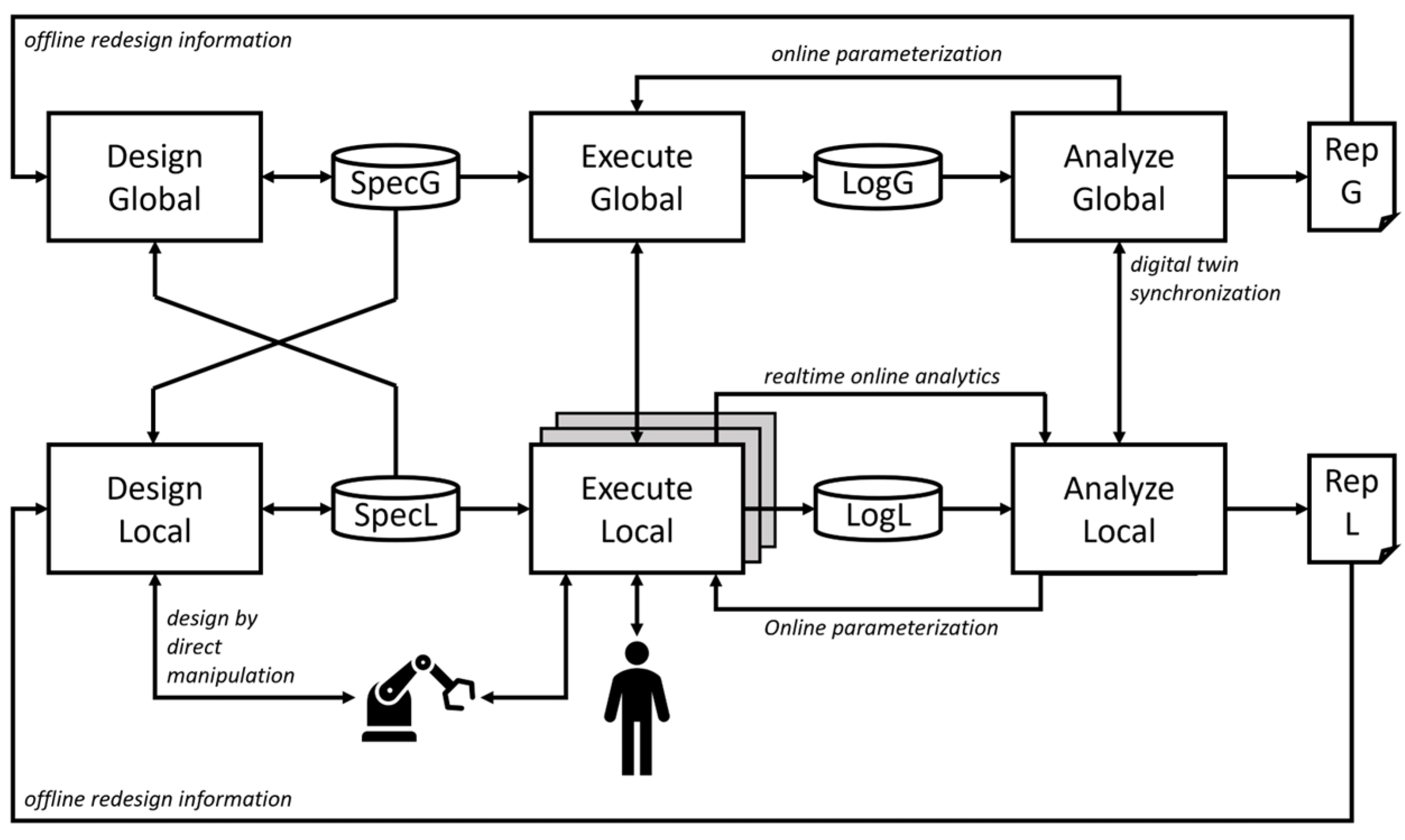
Figure 1. High-level logical software architecture of SHOP4CF [52]. Architecture consists of global and local level, which each consist of design, execute, and analyze modules. The communication between the subsystems can be direct or indirect through different communication means which can store the information on databases (e.g., SpecL).
Machines 10 00957 g001
Figure 2. Top-level logical architecture of the platform [52]. The communication within the architecture happens through vertical neighborhood. SHOP4CF components communicate with each other using FIWARE and are primarily containerized, provided that an abstraction to the hardware layer was integrated.
Machines 10 00957 g002
Figure 3. Data models used in project SHOP4CF. The data models are divided in the design and execution classes. The latter is used for exchanging information during operation, the former is focused on exchanging data during the design of the application [52].
Machines 10 00957 g003
Figure 4. Sensor values of the little finger when Horns (index and little finger straight) and Index straight gestures were made within the time frame. As the little finger is straight in Horns, the sensor value is high, whereas in Index straight the little finger is bent, and the sensor value is low.
Machines 10 00957 g004
Figure 5. M2O2P architecture, where inside the red dashed box is the modules of M2O2P. These M2O2P modules in addition to other modules and components are all containerized, as shown inside the black dashed box. M2O2P consists of three main modules, AC, Web UI, and ROS2-FIWARE bridge, and additionally the eProsima’s© Integration Service. These modules interact with each other using ROS2 and with other components with FIWARE, ROS2, ROS1, and PostgreSQL.
Machines 10 00957 g005
Figure 6. Wireframe of the UI developed for M2O2P component. The UI consists of three main sections: monitor section for general information and task information, calibration section for calibrating the threshold values of the glove, and testing section for training and testing the gestures. Finally, additional options section holds a button to switch filtering by incoming tasks on or off. Since the UI is on one page, the continuation of the page is presented with green arrow.
Machines 10 00957 g006
Figure 7. Flow of the envisioned interaction. The human needs to act as the supervisor of the robot and acknowledge when the robot can move on to the next task. All the operator actions are depicted in the operator lane, all the robot actions are depicted in the robot lane.
Machines 10 00957 g007
Figure 8. Robot cell for the evaluation of the multimodal interface. For ensuring safe collaboration, a UR10 robot and a Sick microscan3 were integrated in the cell. Moreover, a Siemens SIMATIC™ HMI Unified Control Panel was added to display the Web UI.
Machines 10 00957 g008
Figure 9. High-level logical architecture with the use case components mapped on it. MPMS operates on global level and shares the specification through MES with local level components. In execution, the MPMS communicates with the local level components TGT and M2O2P.
Machines 10 00957 g009
Figure 10. Sequence diagram of receiving and completing the task. Each local level component communicates with the MPMS through FIWARE, by receiving task, setting the state of the task to inProgress, and, ultimately, to completed when the task is ready.
Machines 10 00957 g010
Figure 11. Scheme of the experiment. At first between time t0 and t1 the users were debriefed on the experiment and tested a sample task with the glove by also providing initial feedback on the interface. Afterwards, the experiment started at t1 with the first interaction and ended at t2 where the users provided feedback about the interaction. Finally, the second interaction unfolded between t2 and t3 and concluded with the users providing their feeling about the second interaction at t3.
Machines 10 00957 g011
Figure 12. Boxplot representing the final SUS score obtained by the component. The average SUS score was 79.25.
Machines 10 00957 g012
Figure 13. Results from the NASA TLX for the two interactions. The interaction with personalized gestures showed a lower workload compared with the predefined gestures.
Machines 10 00957 g013
Figure 14. Boxplots representing the average score in the (a) mental and (b) physical workload. The personalized interaction displayed a statistically significant lower mental and physical workload when compared with the predefined gestures.
Machines 10 00957 g014
Table 1. All 21 gestures and the corresponding bending states. State of fingers’ bending is presented as numbers varying from 0 (straight, over the upper threshold) to 2 (bent, under the lower threshold).
GestureThumbIndexMiddleRingLittlePose
Horns20220Machines 10 00957 i001
Index and middle straight20022Machines 10 00957 i002
Index and ring straight20202Machines 10 00957 i003
Index, middle, and little straight20020Machines 10 00957 i004
Index, middle, and ring straight20202Machines 10 00957 i005
Index, ring, and little straight20200Machines 10 00957 i006
Middle and little straight22020Machines 10 00957 i007
Middle and ring straight22002Machines 10 00957 i008
Middle straight22022Machines 10 00957 i009
Middle, ring, and little straight22000Machines 10 00957 i010
Little straight22220Machines 10 00957 i011
Point with index20220Machines 10 00957 i012
Ring and little straight22200Machines 10 00957 i013
Ring straight22202Machines 10 00957 i014
Thumb and index straight00222Machines 10 00957 i015
Thumb and little straight02220Machines 10 00957 i016
Thumb, index, and middle straight00022Machines 10 00957 i017
Thumb, index, and little straight00220Machines 10 00957 i018
Thumb, index, middle, and little straight00002Machines 10 00957 i019
Thumb, middle, and little straight02020Machines 10 00957 i020
Thumbs up02222Machines 10 00957 i021
Table 2. Software components used in the use case.
Component NameFunctionality in the Use CaseLevel
Multi-Modal Offline and Online Programming solution (M2O2P)Enables human–robot interactions with sensor gloveLocal
Manufacturing Process
Management System (MPMS)
Orchestrator application that handles process enactment and task assignmentGlobal
Siemens Trajectory
Generation tool (TGT)
Provides trajectory and motion control for the robotLocal
Table 3. Results of gesture recognition accuracy [73].
Problematic GestureNumber of Problematic Interactions
Middle and ring straight1
Index and ring straight1
Number of successful interactions:208
Number of problematic interactions:2
Accuracy of the gesture recognition without readjusting fingers:99.05%
Publisher’s Note: MDPI stays neutral with regard to jurisdictional claims in published maps and institutional affiliations.