Article

Comparison of Two Sinusoidal Magnetization Modes of Bonded Magnetic Rings

1
National Engineering Research Center for Rare Earth, GRINM Group Co., Ltd., Beijing 100088, China
2
GRIREM Advanced Materials Co., Ltd., Beijing 100088, China
3
General Research Institute for Nonferrous Metals, Beijing 100088, China
4
School of Mechanical, Electrical & Information Engineering, Shandong University (Weihai), Weihai 264209, China
*
Author to whom correspondence should be addressed.
Machines 2022, 10(10), 911; https://doi.org/10.3390/machines10100911
Submission received: 7 September 2022 / Revised: 2 October 2022 / Accepted: 4 October 2022 / Published: 8 October 2022
(This article belongs to the Section Electrical Machines and Drives)

Abstract

:
This paper compares the application of two different sinusoidal magnetization methods of a bonded magnetic ring in a permanent magnet motor. Sinusoidal magnetization of a bonded magnetic ring can be realized by eccentric pole cutting or magnetization with eccentric fixture. Firstly, the parametric optimization of the two methods is carried out by finite−element simulation software, with the goal of minimizing the total harmonic distortion (THD) of Air−gap flux density. Then, when the THD of Air−gap flux density is roughly the same, the cogging torque, output torque, back−EMF, magnet dosage, and other parameters of the two magnets in the application of permanent magnet motor are compared. The results show that the performance of the two methods is similar, and the two methods have their own advantages. Finally, an eccentric bonded magnetic ring and eccentric magnetizing fixture are made, respectively, for experimental comparison. The experimental results are consistent with the simulation results. This paper can provide some reference value for the selection of sinusoidal magnetization mode of a bonded magnetic ring.

1. Introduction

Bonded magnetic rings are widely used in permanent magnet motors in automobile, robot, and other fields because of their high forming accuracy, high material utilization, and low assembly cost. Due to the interaction between a permanent magnet and stator teeth and slots in permanent magnet motor, a permanent magnet motor will produce cogging torque, resulting in torque ripple, vibration, and noise [1,2,3], which limits its application in high−precision occasions. In some high−precision applications, we often want to obtain a nearly sinusoidal Air−gap flux density distribution [4,5]. At present, the methods that can realize sinusoidal air−gap flux distribution include eccentric pole cutting [4,6,7,8,9,10,11,12,13,14,15,16,17,18,19], eccentric magnetizing fixture [20,21], and Halbach Array [22,23,24]. Halbach Array is a special magnet array, which can concentrate the magnetic field on one side, while the magnetic field intensity on the other side is almost zero. It has been widely used in nuclear magnetic resonance [25], medical targeted drug guidance [26], rotating motor [27], vibration energy collection device [28], etc. At present, Halbach Array is realized by assembling magnet modules with specific directions, and trying to use sintered magnets. In the application of a permanent magnet motor, block sintered magnets magnetized in a certain direction are often used to splice into a circle, so that a magnetic ring with sinusoidal Air−gap flux density can be obtained [24]. For the bonded magnetic ring, it is very difficult to realize magnetization of the Halbach Array, because it is necessary to ensure that one side has a magnetic gathering effect, so that one side has almost no magnetic field distribution. After magnetization, magnetic fields are often distributed on both sides. It is not a good choice to press bonded magnets into blocks and then form a Halbach Array, through splicing, considering its molding cost and performance.
A bonded magnetic ring is for mixing magnetic particles with adhesive and other additives, and then preparing a permanent magnetic ring through compression, injection, extrusion moulding, and other processes [29,30]. Bonded magnet has the advantages of good performance consistency, accurate size, and high material utilization [31,32]. The process route diagram of bonded magnet made by a conventional compression process is shown in Figure 1 below.
It can be seen, from the production process of bonded magnet in Figure 1, that the magnetic material powder is mixed with adhesive and other additives, and then preloading. After preloading, the pre-pressed blanks are stacked and finally pressed. When the pressing is completed, the Solidification and magnetization treatment shall be carried out. It can be seen from the above steps that if you want to manufacture bonded magnets with special shapes, you only need to process stamping dies with corresponding shapes. This makes it easy to prepare magnets with complex shapes. Moreover, the magnetization of the annular bonded magnet is more flexible, and a variety of magnetization modes can be easily realized by changing the shape of the magnetization fixture. Therefore, in order to realize a sinusoidal Air−gap flux density distribution, there are two ways to realize the bonded magnetic ring: eccentric pole cutting and eccentric magnetization fixture. For eccentric pole cutting, the special-shaped bonded magnetic ring can be directly prepared by designing the pressing die with a corresponding shape, without secondary processing, the material utilization rate is 100%, and the processing cost is little changed compared with the conventional bonded magnetic ring. Another method is to adjust the shape of the magnetizing fixture to realize the sinusoidal Air−gap flux density distribution of the bonded magnetic ring. There is no change in the production process between the eccentric pole cutting or eccentric magnetizing fixture method and the traditional radial magnetizing bonded magnetic ring, so there is no change in the cost of processing and manufacturing.
When we process the bonded magnetic ring using the eccentric pole cutting method, there is no difference from the original bonded magnetic ring production process. Thanks to the characteristics of large degree of freedom of shape in the processing and manufacturing process of bonded magnets, we can directly press the bonded magnetic ring with eccentric pole cutting by designing a pressing die of corresponding shape. The special-shaped bonded magnetic ring made by the eccentric pole cutting method uses fewer magnetic particles than the conventional bonded magnetic ring, which will have some advantages in cost. When we process the bonded magnetic ring of the eccentric magnetizing fixture, the process does not change. Benefiting from the flexible magnetizing characteristics of the bonded magnetic ring, the corresponding bonded magnetic ring can be obtained by designing the corresponding eccentric magnetizing fixture in the magnetizing process.
The bonded magnetic ring manufactured by the two methods is used as the inner rotor, and the assembly method is the same as that of the rotor used in the original motor, so the cost of assembly is unchanged.
At present, there is little research on the magnetic flux density distribution of sinusoidal air gap realized by bonded magnetic rings. Based on the two characteristics of high degree of freedom of bonded magnetic ring forming and high magnetic filling flexibility, this paper explores the difference between the corresponding two sinusoidal realization methods, and provides a reference for the selection of the sinusoidal realization method of bonded magnetic rings. Firstly, the bonded magnetic ring is briefly introduced, and then, aiming at minimizing the total harmonic distortion (THD) of Air−gap flux density, the two methods of eccentric pole cutting bonded magnetic ring and eccentric magnetization fixture are optimized by using finite-element simulation software. Then, the bonded magnetic ring optimized by the two methods is further simulated in the permanent magnet motor, and the differences of cogging torque, output torque, and back−EMF are compared. Finally, the eccentric pole cutting bonded magnetic ring and eccentric magnetization fixture are made, and the magnet is installed and tested.

2. Finite Element Analysis

In order to compare the differences between the two methods, a six-slot, four-pole permanent magnet synchronous motor using a four-pole bonded magnetic ring is introduced for analysis. The motor parameters are shown in Table 1.
In order to ensure a single variable in the simulation process, the two methods use the same material parameters, simulation initial conditions, boundary conditions, etc. The simulation flow diagram is shown in Figure 2.
Since the magnetization direction of the anisotropic bonded magnet is greatly affected by the previous orientation, it is not easy to change the magnetic flux density distribution on the surface of the magnetic ring by changing the shape of the magnetizing fixture [33]. Therefore, this paper uses isotropic materials for simulation. The performance parameters of bonded magnets used are shown in Table 2. The bonded magnet used in the original motor is the same material as the eccentric pole cutting and eccentric magnetizing fixture. The size of the bonded magnetic ring used in the original motor is the same as that used in the eccentric magnetization fixture method, with an inner diameter of 18 mm, an outer diameter of 26 mm, and a height of 15 mm. Radial quadrupole magnetization is used for magnetization. The original motor uses the same stator, rotor core, and control board as the motor using eccentric pole cutting and eccentric magnetizing fixture. Only the shape or magnetizing method of the bonded magnetic ring used is different. Under normal conditions, the maximum operating temperature of the original motor is not higher than 70 ℃.

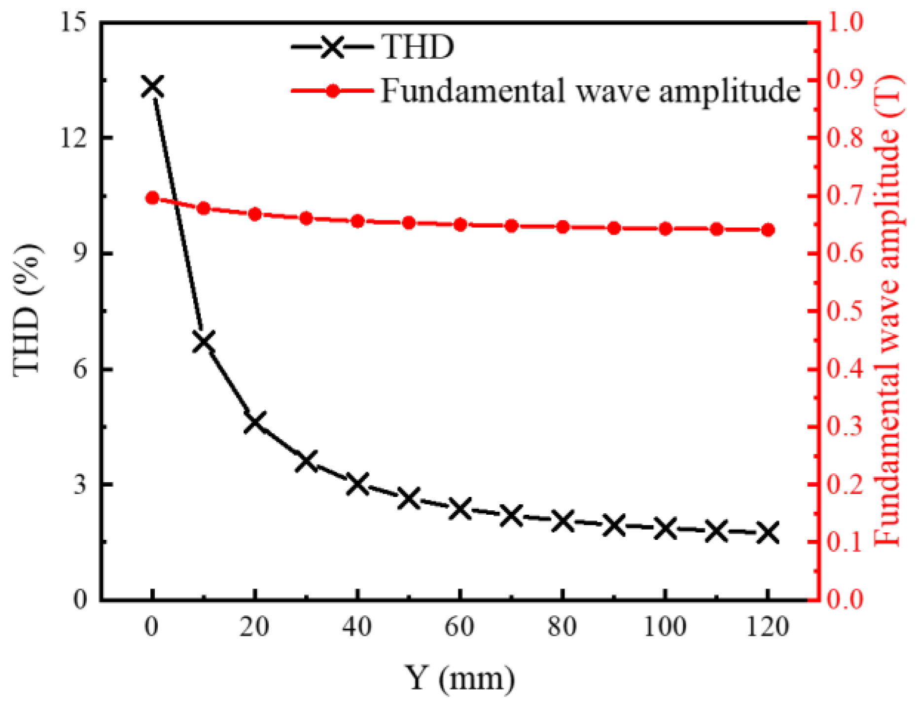
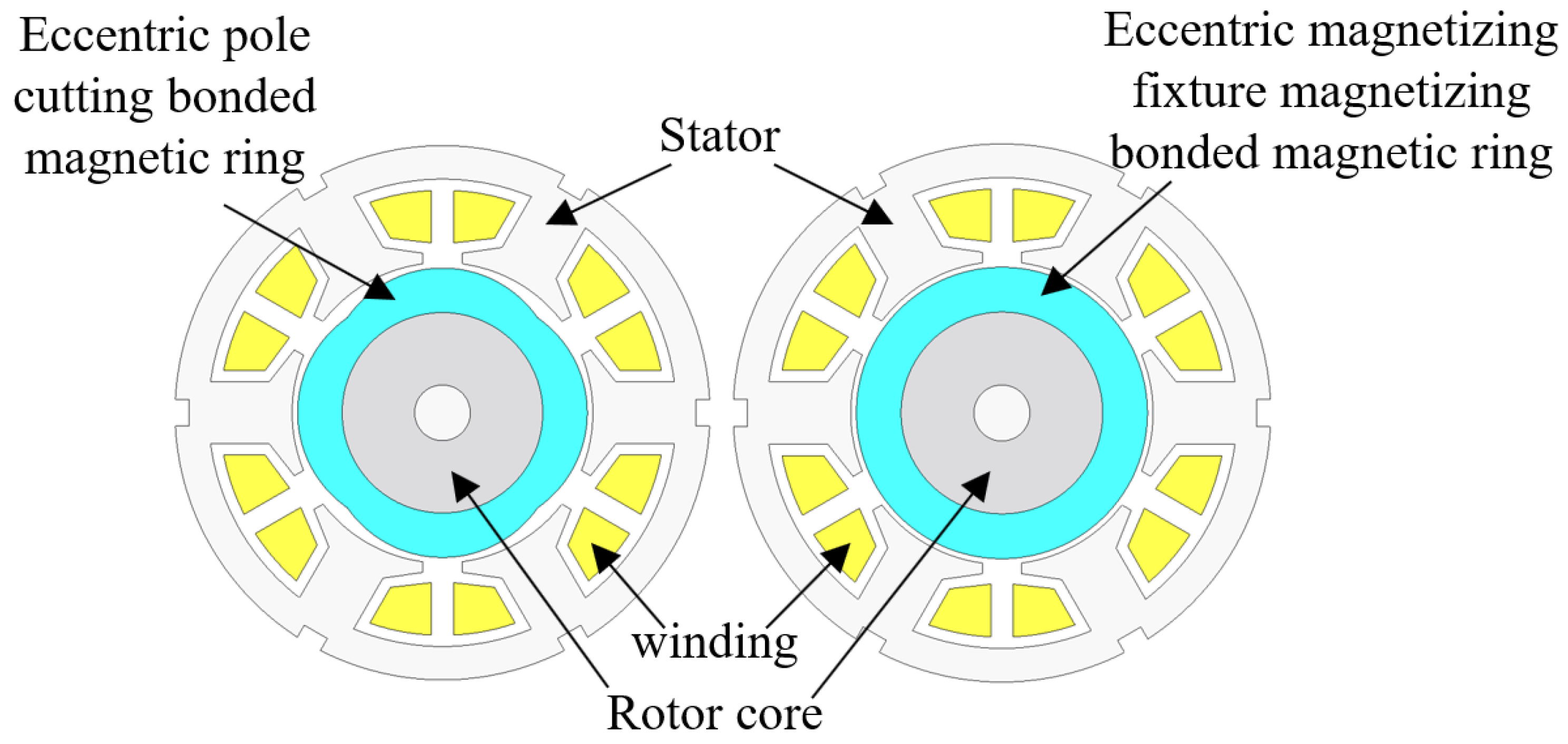
2.1. Eccentric Pole Cutting

Eccentric pole cutting is widely used in surface-mounted motors, and the analytical calculation formula is derived in [4,6,13]. At present, this method is widely used in sintered magnetic tile and less in bonded magnetic ring. The schematic diagram of eccentric pole cutting magnetic ring and magnetization simulation cloud chart are shown in Figure 3 below.
As shown in Figure 3, the eccentricity of the eccentric pole cutting bonded magnetic ring is scanned parametrically, and the bonded magnetic ring under different eccentricity (x) is magnetized and simulated. The optimization objective is to minimize the THD of Air−gap flux density, and the eccentricity x is set to the scanning range of 0–4 mm. The relationship between the THD and fundamental wave amplitude of Air−gap flux density and eccentricity is shown in Figure 4 below.
As can be seen from Figure 4, with the increase in the eccentricity of the bonded magnetic ring with eccentric pole cutting, the THD of Air−gap flux density first decreases and then increases. The fundamental wave amplitude decreases gradually. The THD of Air−gap flux density reaches the minimum when the eccentricity x = 3 mm, which is about 3.37%. At this time, the fundamental wave amplitude is about 0.65 T.

2.2. Eccentric Magnetizing Fixture

For the permanent magnetic ring, the magnetization mode of the permanent magnetic ring can also be changed by changing the shape of the magnetization fixture. The back iron is made of silicon steel sheet material, and the center core is made of non-magnetic material. The schematic diagram of eccentric magnetizing fixture is shown in Figure 5. The schematic diagram of eccentric magnetization fixture and the simulation cloud diagram of eccentric magnetization fixture are shown in Figure 5.
The eccentricity of the magnetizing fixture is scanned parametrically, and the magnetic property distribution of the bonded magnetic ring under different eccentricities is calculated. The optimization objective is to minimize the THD of Air−gap flux density, and the eccentricity y is set to the scanning range of 0–120 mm. The relationship between the THD and fundamental wave amplitude of Air−gap flux density and eccentricity is shown in Figure 6 below.
During the magnetization simulation of the permanent magnetic ring with the eccentric magnetization fixture, in order to obtain an Air−gap flux density distribution as close to sinusoidal as much as possible, the center core of the magnetization fixture adopts non-magnetic material, so when the eccentricity is y = 0, the THD of Air−gap flux density is less than when the eccentricity of the eccentric pole cutting bonded magnetic ring is x = 0. As can be seen from Figure 6, the THD and fundamental wave amplitude of Air−gap flux density decrease with an increase in eccentricity. When the eccentricity is greater than 20 mm, the reduction speed decreases significantly.
When the eccentricity y = 40 mm, using the eccentric magnetizing fixture method, the THD value and fundamental wave amplitude of the Air−gap flux density obtained are better than using the eccentric pole cutting method. As the eccentricity y continues to increase, the THD of the Air−gap flux density can continue to decrease. When the eccentricity y = 120 mm, the THD of the Air−gap flux density decreases to 1.75%, which is about 51.9% of the optimal result of the eccentric pole cutting method. The fundamental amplitude is 0.641 T, which is about 0.009 T lower than the optimal solution of the eccentric pole cutting method. Therefore, for the motor in this case, the method of using eccentric magnetizing fixture can obtain better results just from the THD of Air−gap flux density.

3. Comparison in Motor Application

In order to further compare the advantages and disadvantages of the two methods in motor application, the eccentricity of the two methods, in which the THD of the Air−gap flux density is small and similar, and the fundamental wave amplitude of the Air−gap flux density is also similar, is adopted. For the bonded magnetic ring with eccentric pole cutting, take the eccentricity x = 3 mm, THD = 3.37%, and the fundamental wave amplitude is about 0.65 T. For the bonded magnetic ring magnetized with eccentric magnetizing fixture, the eccentricity is y = 40 mm, THD = 3.02%, the fundamental wave amplitude is about 0.656 T. The test structure of the bonded magnetic ring [34], the original motor, and the simulation comparison of the Air−gap flux density of the bonded magnetic ring obtained by two methods are shown in Figure 7 below. The sinusoidal degree of the bonded magnetic ring obtained by eccentric pole cutting or eccentric magnetizing fixture method is obviously improved compared with the bonded magnetic ring of the original motor, and the peak value of the air gap magnetic density is improved compared with the bonded magnetic ring of the original motor. The air gap magnetic density of the bonded magnetic ring using the eccentric magnetization fixture method is slightly higher.
The schematic diagram of two kinds of bonded magnetic rings in the motor is shown in Figure 8.

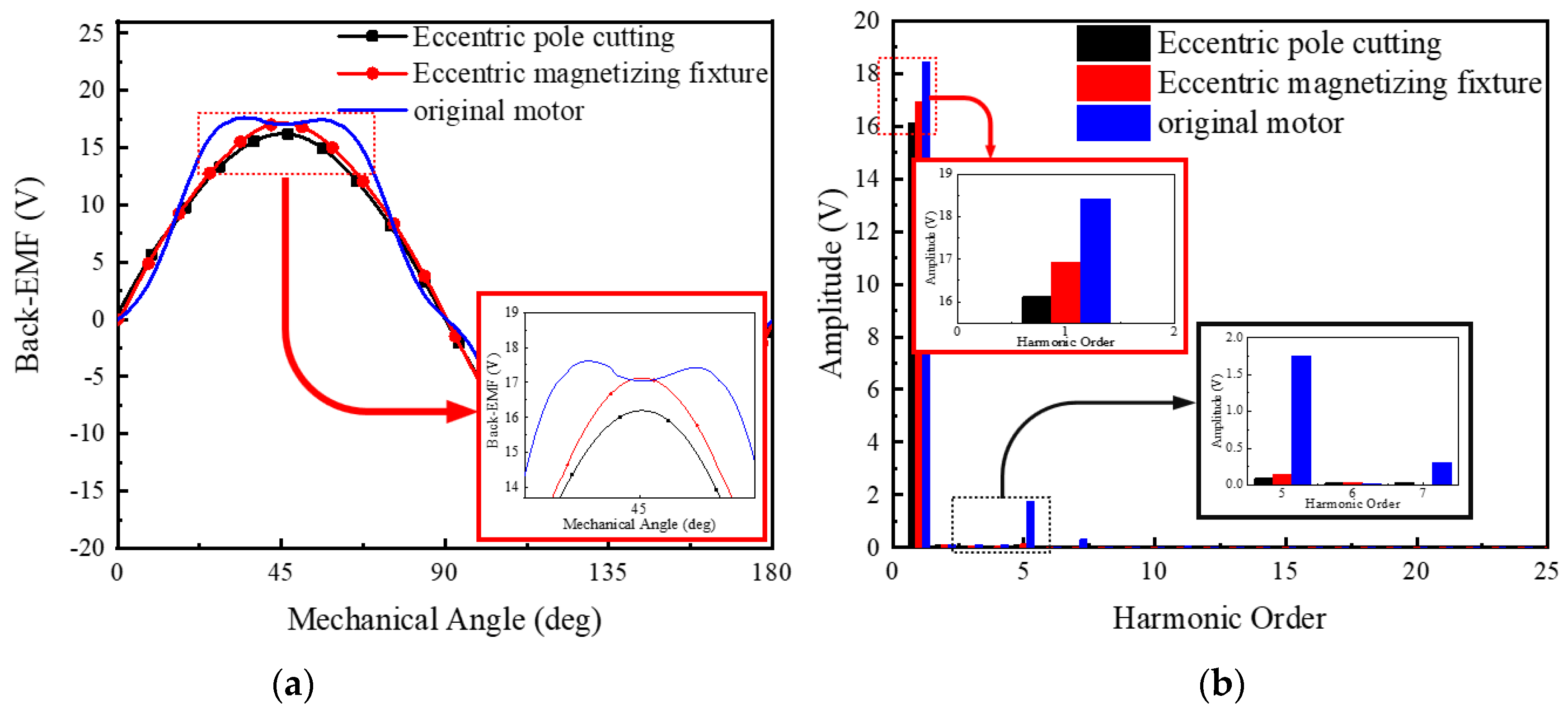
3.1. Comparison of No−Load Back−EMF

The Fourier transform analysis of the original motor, no−load back−EMF, and no−load back−EMF using eccentric pole cutting and eccentric magnetizing fixture methods is shown in Figure 9 below.
It can be seen from Figure 9a that the no−load back−EMF of the motor using eccentric pole cutting and eccentric magnetizing fixture is significantly more sinusoidal than that of the original motor. At the same time, the amplitude of no−load back−EMF fundamental wave is also lower than that of the original motor. It can be seen from Figure 9b that the amplitude of no−load back−EMF fundamental wave is reduced by 11.4% using the eccentric pole cutting method, and the amplitude of no−load back−EMF fundamental wave is reduced by 10.7% using eccentric magnetizing fixture method. By using eccentric pole cutting and eccentric magnetizing fixture, the fifth harmonic optimization of the original motor is the most obvious, which decreases by 89.5% and 93.3%, respectively. The THD value of no−load back−EMF of the original motor is 9.4%, the THD of the no−load back−EMF of the permanent magnet motor using the eccentric pole cutting method is 1.1%, and the THD of the no−load back−EMF of the permanent magnet motor using the eccentric magnetizing fixture is 0.77%. From this comparison, it can be seen that the method using eccentric magnetizing fixture is slightly better than the eccentric pole cutting method.

3.2. Cogging Torque Comparison

The cogging torque of the motor corresponding to the two methods is shown in Figure 10. The cogging torque amplitude of the motor with eccentric pole cutting bonded magnetic ring is slightly larger than that of the motor with eccentric magnetizing fixture magnetized bonded magnetic ring.
It can be seen from Figure 10a that the two methods of eccentric pole cutting and eccentric magnetizing fixture can effectively reduce the cogging torque, and the effects of the two methods are equivalent. The cogging torque of the permanent magnet motor using the eccentric pole cutting method is reduced by 93.58%, and the cogging torque of the permanent magnet motor using the eccentric magnetizing fixture is reduced by 91.8%. In this paper, the eccentricity selected for the eccentric magnetizing fixture is 40 mm. It is found in the simulation that the cogging torque can be further reduced with tan increase in eccentricity, as shown in Figure 10b below. If the cogging torque is optimized, the eccentric magnetizing fixture will have more optimization space.

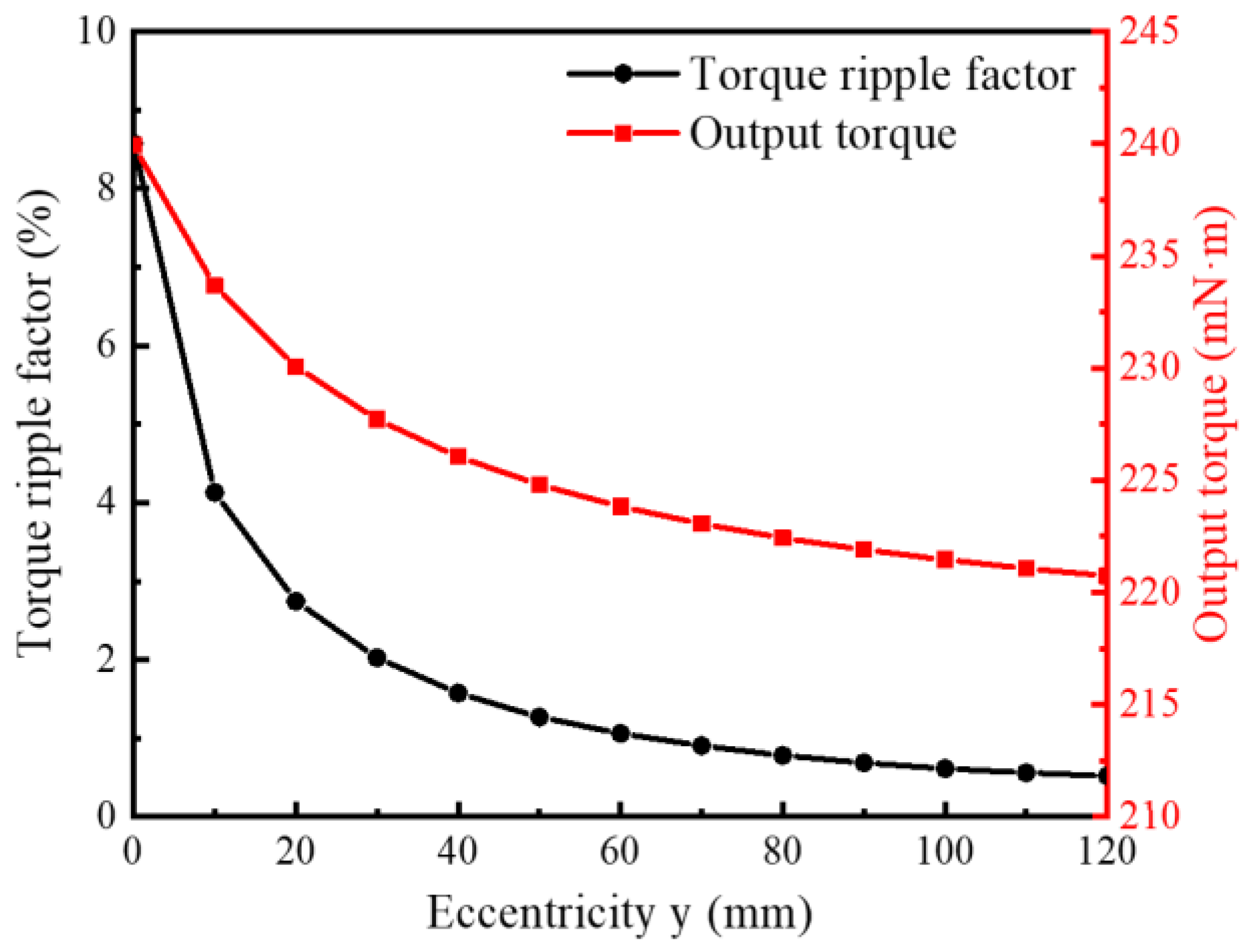
3.3. Comparison of Rated Output Torque

The rated output torque of the motor using the two methods is shown in Figure 11. It can be seen that using these two methods can effectively reduce torque ripple. After the sinusoidal magnetization is realized by the two methods, the magnetic flux in the air gap of the permanent magnet motor decreases, resulting in the reduction in the output torque. The effective value of the output torque of the eccentric pole cutting method is reduced by 10.4%, and the output torque of the eccentric magnetizing fixture method is reduced by 9.6%. The output torque of permanent magnet motor with eccentric magnetizing fixture decreases less, and the advantages of this method will be more obvious on higher−power machines.
Define torque ripple factor:
ρ = T m a x T m i n T a v
where ρ is the torque ripple factor, Tmax is the maximum value of output torque, Tmin is the minimum value, and Tav is the average value. According to formula 1, the torque ripple factor of the original motor ρ = 13.04%, the torque ripple factor of a bonded magnetic ring motor with eccentric pole cutting is ρ = 2.51%, and the torque ripple factor of the motor with the bonded magnetic ring magnetized by the eccentric magnetizing fixture is ρ = 1.57%.
The eccentricity of the eccentric magnetizing fixture used in this paper is 40 mm. If the eccentricity is further increased, the torque ripple factor of the output torque can be further reduced, and the effective value of the output torque will also be reduced, as shown in Figure 12. When the torque ripple factor of the motor output torque is required to be higher, the eccentric magnetizing fixture method can achieve better results.

3.4. Comparison of Magnet Dosage

When the density of the bonded magnetic ring used in the two methods is the same (6.0 g/cm), the weight of the eccentric pole cutting bonded magnetic ring is 22.15 g, and the weight of the eccentric magnetizing fixture magnetized bonded magnetic ring is 24.88 g, that is, the eccentric pole cutting bonded magnetic ring can save 10.97% of the magnetic powder.

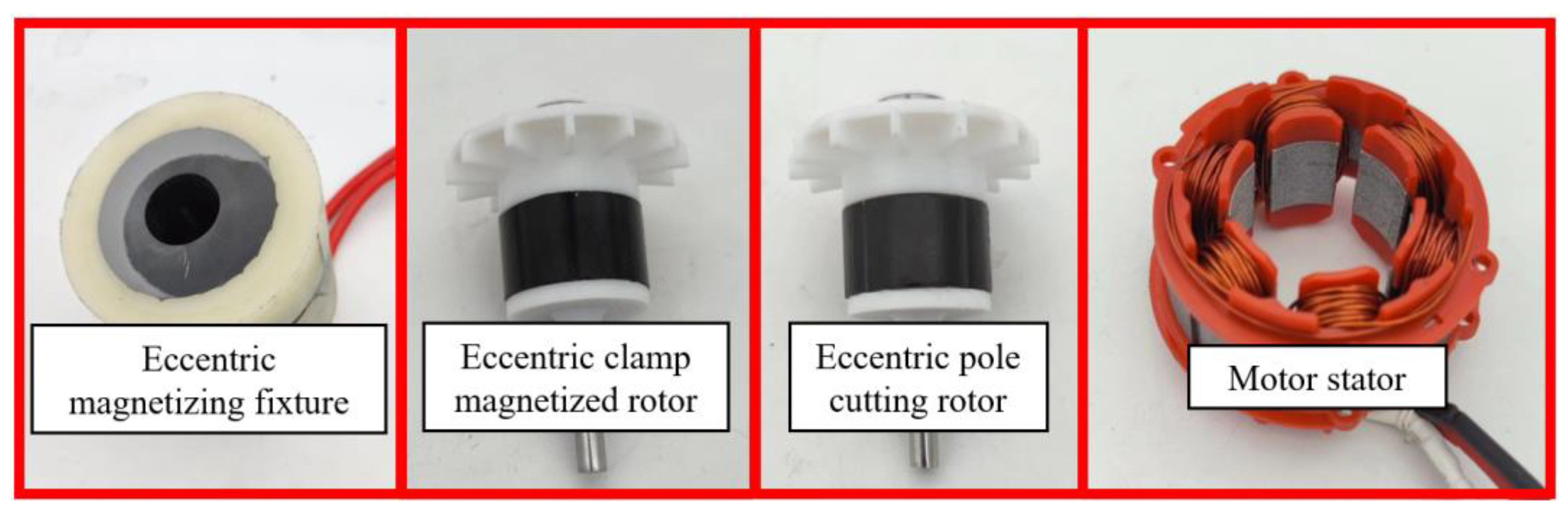
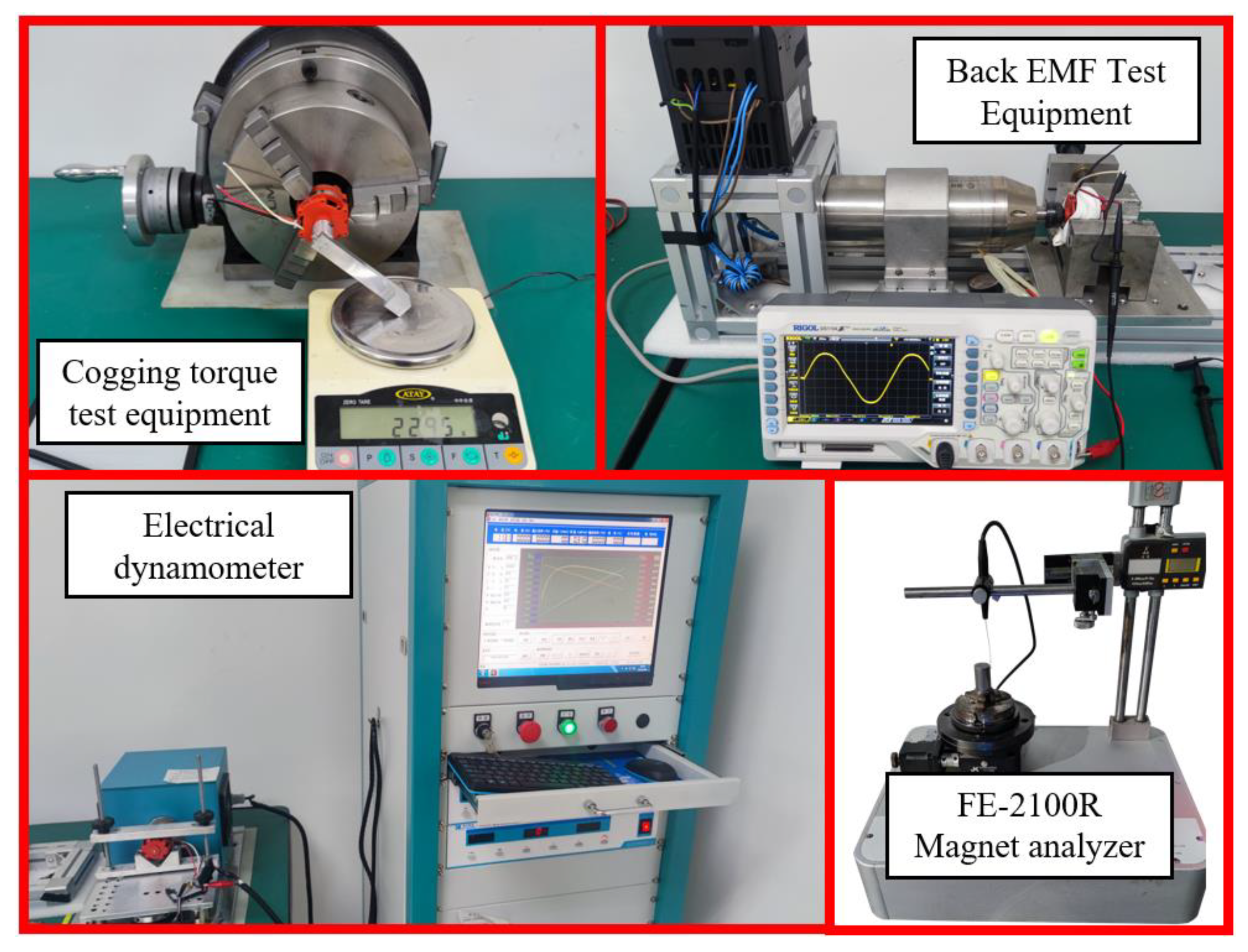
4. Prototype Comparison

According to the above calculation results, a prototype is made for testing. The eccentric fixture with an eccentricity of 40 mm, the bonded magnetic ring magnetized by the eccentric fixture, the bonded magnetic ring with an eccentricity pole cutting of 3 mm, and the stator used in the test are shown in Figure 13. Both permanent magnets are isotropic bonded Nd−Fe−B materials.
The equipment used in the experiment is shown in Figure 14.

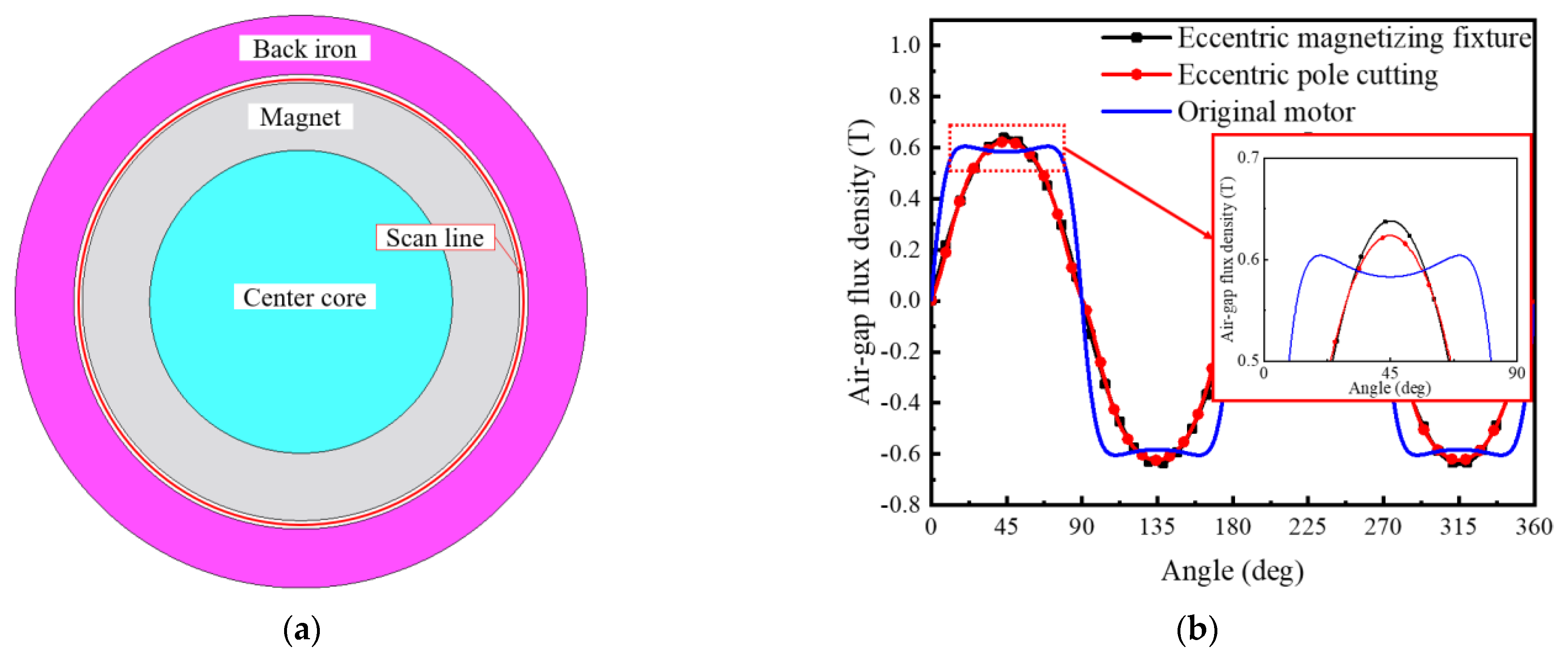
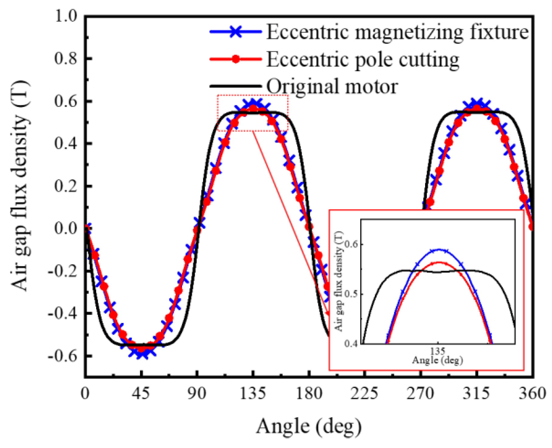
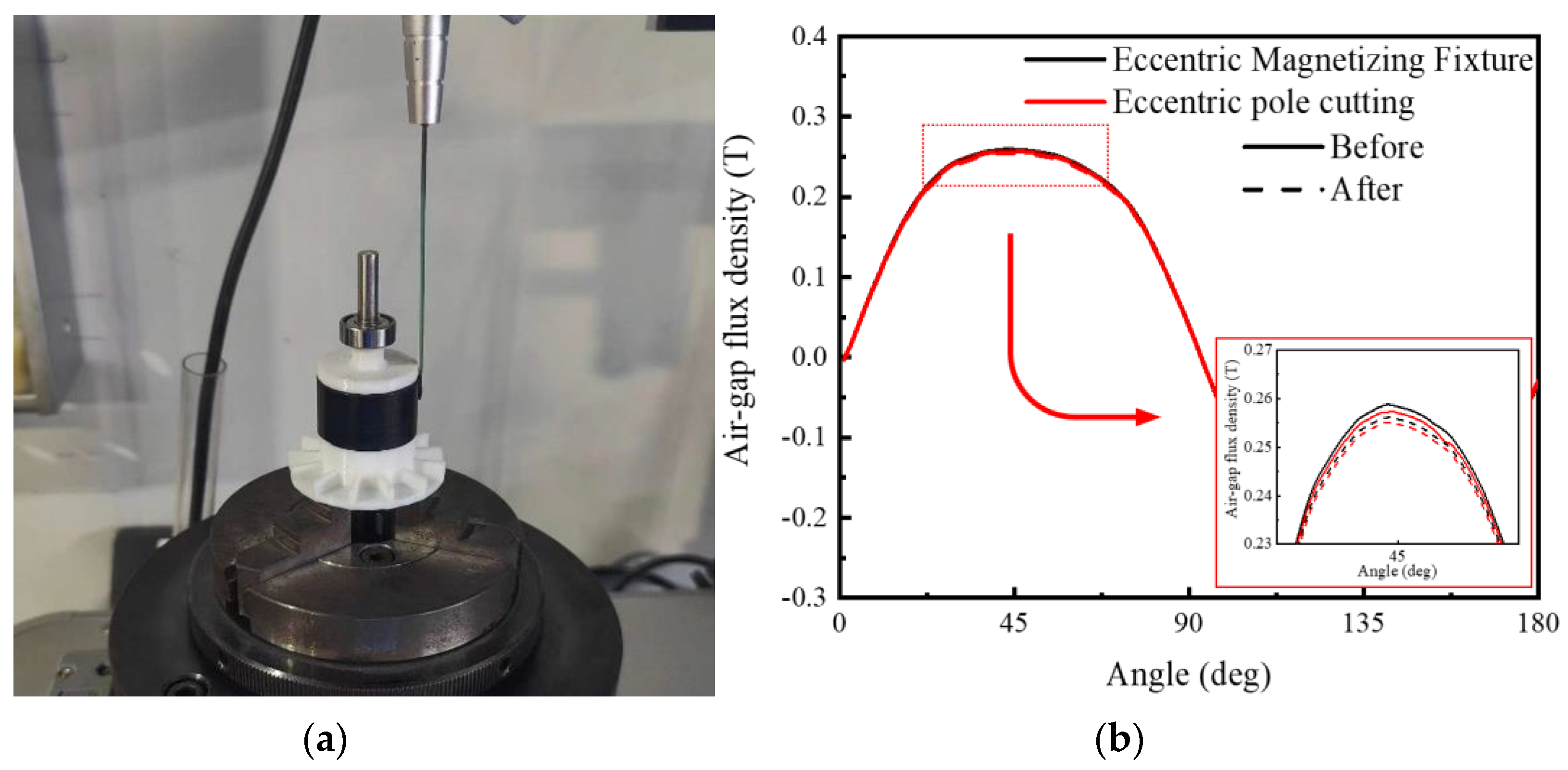
4.1. Air−Gap Flux Density Comparison

The bonded magnetic ring used by the original motor and the bonded magnetic ring using eccentric pole cutting and eccentric magnetizing fixture are placed in the center core and back iron, respectively, for the air−gap magnetic flux test after magnetization, and the FE−2100R magnet analyzer in Figure 14 is used for the test. The test results are shown in Figure 15 below.
It can be seen from Figure 15 that an Air−gap flux density close to sine can be obtained by using eccentric pole cutting or eccentric magnetizing fixture methods. The amplitude of the fundamental wave of the Air−gap flux density of the bonded magnetic ring using the eccentric pole cutting method is 0.572 T, and the THD of the Air−gap flux density is 2.29%. The amplitude of the fundamental wave of the Air−gap flux density of the bonded magnetic ring using the eccentric magnetizing fixture method is 0.593 T, and the THD of the Air−gap flux density is 1.47%. The amplitude of the fundamental wave of the Air−gap flux density of the bonded magnetic ring used in the original motor is 0.665 T, and the THD of the Air−gap flux density is 24.17%. The difference between the measured value and the simulated value of the fundamental amplitude of the Air−gap flux density is about 7%, and the actual THD test result of the Air−gap flux density is also close to the simulation result.

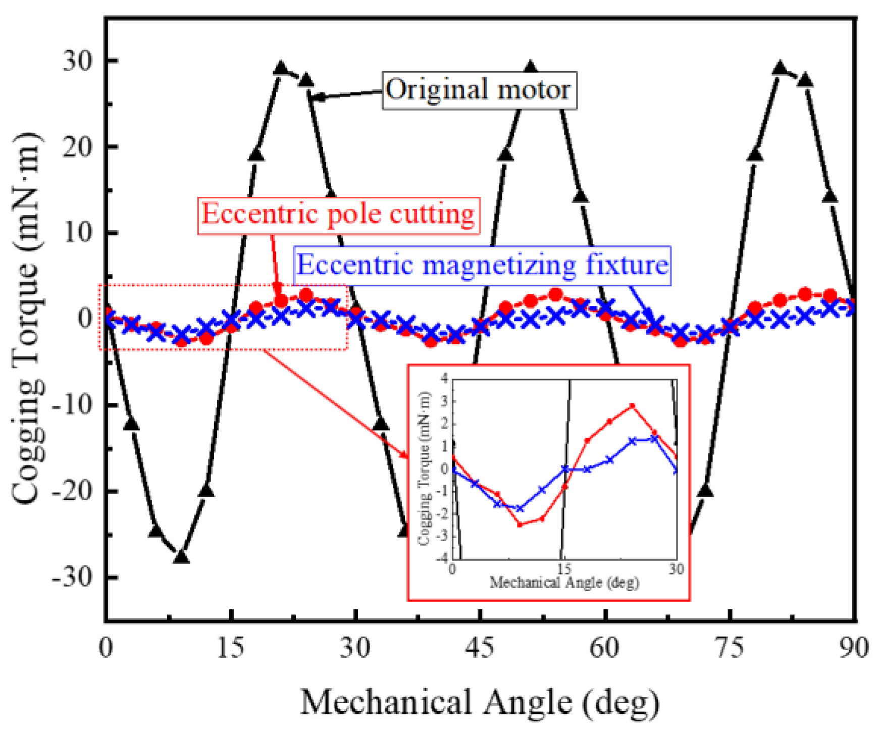
4.2. Cogging Torque Comparison

The magnetized bonded magnetic ring of eccentric fixture and the bonded magnetic ring of eccentric pole cutting are installed and tested. The cogging torque is tested using the cogging torque test equipment in Figure 14. The test results are compared with the traditional four−pole bonded magnetic ring as shown in Figure 16.
It can be seen from Figure 16 that the two sinusoidal realization methods of bonded magnetic rings can effectively reduce the cogging torque. The PK–PK value of cogging torque of bonded magnetic rings using eccentric pole cutting method is 5.27 mN·m, which is reduced by 90.71%. The PK–PK value of cogging torque of bonded magnetic ring magnetized by eccentric magnetizing fixture is 3.09 mN·m, which is reduced by 94.56%. Both simulation and measurement results can optimize more than 90%, and the simulation and measurement are in good agreement.

4.3. Comparison of No−Load Back−EMF

The motors manufactured by the two sinusoidal realization methods are tested with the no−load back−EMF test equipment in Figure 14. The speed is set to 18,000 rpm, and the test results are shown in Figure 17 below.
It can be seen from Figure 17 that the no−load back−EMF close to sine can be obtained by using eccentric pole cutting or eccentric magnetizing fixture methods. The amplitude of no−load back−EMF fundamental wave using eccentric magnetizing fixture method is slightly higher than that using eccentric pole cutting method. The amplitude of no−load back−EMF fundamental wave using eccentric pole cutting method is 16.1 V, and the amplitude of no−load back−EMF fundamental wave using eccentric magnetizing fixture method is 16.9 V, which is about 4% different from the simulation results. The THD value of no−load back−EMF of the permanent magnet motor using eccentric pole cutting method is 1.03%, and the THD value of no−load back−EMF of the permanent magnet motor using eccentric magnetizing fixture method is 1.28%, which is significantly increased compared with 9.73% in the original motor. The results are in good agreement with the simulation results.

4.4. Demagnetization Test

The coercivity of bonded magnets is lower than that of sintered magnets, and demagnetization easily occurs at high temperatures and demagnetizing fields. Therefore, it is necessary to analyze and compare the demagnetization risks of bonded magnets. The maximum working temperature of the bonded magnet in this case is 160 °C. The motor used in this case is equipped with a fan, and the heat dissipation is good. A test is conducted on the magnetic flux density distribution on the rotor surface when the rotor operates continuously for 1 h under the load of 100 mN·m. The meter magnetic analyzer in Figure 13 is used for the test. Place the rotor before and after the load on the test bench, directly test its surface magnetic flux density (without yoke), and then place the rotor after the load operation. The test results are shown in Figure 18 below.
It can be seen from the test results in Figure 18b that the bonded magnetic ring undergoes slight demagnetization when the motor operates under the load of 100 mN·m for 1 h. To facilitate the calculation of demagnetization rate, the change in magnetic area (the area enclosed by the magnetic flux density curve on the magnetic ring surface and the abscissa) is taken as the measurement standard. Using the eccentric magnetizing fixture method, the magnetic force area is 33.26 T*deg before demagnetization, 32.92 T*deg after demagnetization, and the demagnetization rate is 1.02%. Using the eccentric pole cutting method, the magnetic force area is 33.09 T*deg before demagnetization, 32.80 T*deg after demagnetization, and the demagnetization rate is 0.88%. Using both methods, the demagnetization rate is less than 2%.

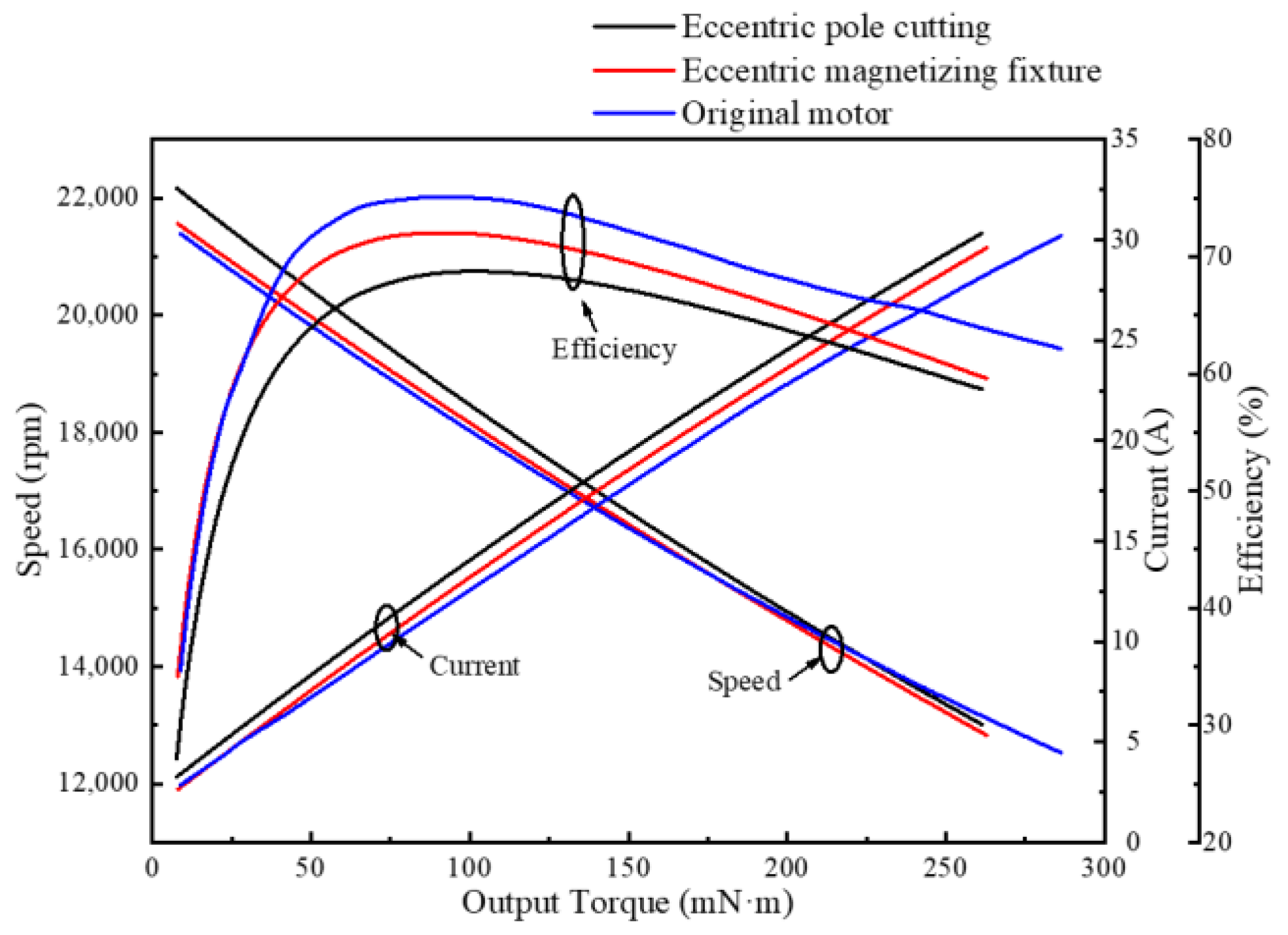
4.5. Motor Performance Test

Using the dynamometer equipment in Figure 14 to test the motor performance, the test results are shown in Figure 19 below.
It can be seen from Figure 19 that the two methods have similar speed and torque operation ranges and similar efficiency. Among them, the efficiency of the permanent magnet motor using the eccentric magnetizing fixture method is slightly higher, and the performance is slightly better than that of the permanent magnet motor using the eccentric pole cutting method. For motors using eccentric pole cutting and eccentric magnetizing fixture methods, stator silicon steel sheets of the same material and size and the same windings are used. However, in the test, the Air−gap flux density of the bonded magnetic ring using eccentric pole cutting method is slightly lower than that of the bonded magnetic ring using eccentric magnetizing fixture, which reduces its back−EMF and output torque. In order to achieve the same output torque, it needs more current, that is, the KT value of the motor is smaller ( K T = N 2 π , which means the torque generated by the unit current of the motor). This leads to a higher current value of the motor using the eccentric pole cutting method under the same torque, that is, the copper loss, iron loss, and other losses become larger, resulting in a lower efficiency. In order to effectively improve its efficiency, on the premise of not changing the motor size, the best solution is to increase the number of turns of the motor winding. Since the difference between KT values is small, the number of turns will increase very little.

5. Conclusions

From the above analysis, it can be seen that the use of eccentric pole cutting method or eccentric magnetizing fixture method can well achieve the sinusoidal magnetization of Air−gap flux density. Compared with the four−pole radial magnetized bonded magnetic ring used in the original motor, the processing flow of the bonded magnetic ring using the two methods has no change. For the eccentric pole cutting method, due to the good shape flexibility of the bonded magnet in the forming process, a special−shaped bonded magnetic ring with eccentric pole cutting can be obtained by making a special−shaped stamping die. As for the eccentric magnetizing fixture method, due to the high flexibility of bonded magnets, it is only necessary to design the corresponding eccentric magnetizing fixture in the subsequent magnetizing process, and the cost of this kind of magnetizing fixture has no change compared with the traditional radial magnetizing fixture.
Both methods can effectively reduce cogging torque by more than 90%, and can also effectively reduce the torque ripple of the output torque. In view of the above results, the two methods are recommended as follows:
  • On the premise that the optimization effect reaches the standard, it is recommended to use the eccentric pole cutting method in the mass production process, which can reduce the amount of bonded magnetic powder and thus reduce the material cost.
  • Since the eccentric pole cutting method has better optimization effect, it is recommended to use the eccentric magnetizing fixture in the scene pursuing higher optimization effect.
The corresponding optimization methods can be selected according to needs.

Author Contributions

Conceptualization, Z.W., Y.L. and D.Y.; Funding acquisition, Z.W., Y.L., W.Y. and L.W.; Investigation, Y.Y.; Methodology, Z.Z. and J.Y.; Software, Z.Z.; Validation, Z.Z. and T.H.; Writing—original draft, Z.Z.; Writing—review and editing, Z.Z. and J.Y. All authors have read and agreed to the published version of the manuscript.

Funding

This research was funded by National Key Research and Development Program of China, grant number 2021YFB3500201; National Key Research and Development Program of China, grant number 2021YFB3500202; National Key Research and Development Program of China, grant number 2021YFB3500205; Beijing NOVA Program, grant number Z211100002121092; Natural Science Foundation of Hebei Province, grant number E2021103006; Hebei Province International Science and Technology Cooperation Base Construction Project of China, grant number 20591002D.

Institutional Review Board Statement

Not applicable.

Informed Consent Statement

Not applicable.

Acknowledgments

We gratefully acknowledge the assistance of Zhang Kanyu, Yao Hailan, and Zhang Zhijin of IDAJ−CHINA in the simulation software.

Conflicts of Interest

Ze Zhang, Zilong Wang, Juntao Yu, Dunbo Yu, Yang Luo, Wenlong Yan, Yuanfei Yang, Tengfei Hu, and Li Wang declare that they have no financial and personal relationships with other people or organizations that can inappropriately influence their work, there is no professional or other personal interest of any nature or kind in any product, service, and/or company that could be construed as influencing the position presented in, or the review of, the manuscript entitled “Comparison of two sinusoidal magnetization modes of bonded magnetic ring”.

References

  1. Fei, W.; Luk, P.C.K. A New Technique of Cogging Torque Suppression in Direct−Drive Permanent−Magnet Brushless Machines. IEEE Trans. Ind. Appl. 2010, 46, 1332–1340. [Google Scholar] [CrossRef] [Green Version]
  2. Dorrell, D.G.; Hsieh, M.F.; Popescu, M.; Evans, L.; Staton, D.A.; Grout, V. A Review of the Design Issues and Techniques for Radial−Flux Brushless Surface and Internal Rare−Earth Permanent−Magnet Motors. IEEE Trans. Ind. Electron. 2010, 58, 3741–3757. [Google Scholar] [CrossRef]
  3. Li, R.; Shi, C.; Qu, R.; Li, D.; Ren, X.; Fedida, V.; Zhou, Y. A Novel Modular Stator Fractional Pole−Pair Permanent−Magnet Vernier Machine with Low Torque Ripple for Servo Applications. IEEE Trans. Magn. 2020, 57, 1–6. [Google Scholar] [CrossRef]
  4. Jabbari, A. An Analytical Expression for Magnet Shape Optimization in Surface−Mounted Permanent Magnet Machines. Math. Comput. Appl. 2018, 23, 57. [Google Scholar] [CrossRef] [Green Version]
  5. Wu, L.; Zhu, Z.Q. Analytical Modeling of Surface−Mounted PM Machines Accounting for Magnet Shaping and Varied Magnet Property Distribution. IEEE Trans. Magn. 2014, 50, 1–11. [Google Scholar] [CrossRef]
  6. Zhou, Y.; Li, H.; Meng, G.; Zhou, S.; Cao, Q. Analytical Calculation of Magnetic Field and Cogging Torque in Surface−Mounted Permanent Magnet Machines Accounting for Any Eccentric Rotor Shape. IEEE Trans. Ind. Electron. 2014, 62, 3438–3447. [Google Scholar] [CrossRef]
  7. Chu, W.Q.; Zhu, Z.Q. Investigation of Torque Ripples in Permanent Magnet Synchronous Machines with Skewing. IEEE Trans. Magn. 2012, 49, 1211–1220. [Google Scholar] [CrossRef]
  8. Li, Y.; Xing, J.; Wang, T.; Lu, Y. Programmable Design of Magnet Shape for Permanent−Magnet Synchronous Motors with Sinusoidal Back−EMF Waveforms. IEEE Trans. Magn. 2008, 44, 2163–2167. [Google Scholar] [CrossRef]
  9. Zheng, P.; Zhao, J.; Han, J.; Wang, J.; Yao, Z.; Liu, R. Optimization of the Magnetic Pole Shape of a Permanent−Magnet Synchronous Motor. IEEE Trans. Magn. 2007, 43, 2531–2533. [Google Scholar] [CrossRef]
  10. Merkel, M.; Gangl, P.; Schöps, S. Shape Optimization of Rotating Electric Machines Using Isogeometric Analysis. IEEE Trans. Energy Convers. 2021, 36, 2683–2690. [Google Scholar] [CrossRef]
  11. Kong, X.; Hua, Y.; Zhang, Z.; Wang, C.; Liu, Y. Analytical Modeling of High−Torque−Density Spoke−Type Permanent Magnet In−Wheel Motor Accounting for Rotor Slot and Eccentric Magnetic Pole. IEEE Trans. Transp. Electrif. 2021, 7, 2683–2693. [Google Scholar] [CrossRef]
  12. Dhulipati, H.; Mukundan, S.; Li, Z.; Ghosh, E.; Tjong, J.; Kar, N.C. Torque Performance Enhancement in Consequent Pole PMSM Based on Magnet Pole Shape Optimization for Direct−Drive EV. IEEE Trans. Magn. 2020, 57, 1–7. [Google Scholar] [CrossRef]
  13. Hu, P.; Wang, D. Analytical Average Torque Optimization Method of Parallel Magnetized Surface−Mounted Permanent−Magnet Machine with Third−Order Harmonic Shaping Method. IEEJ Trans. Electr. Electron. Eng. 2020, 15, 1377–1383. [Google Scholar] [CrossRef]
  14. Du, Z.S.; Lipo, T.A. High Torque Density and Low Torque Ripple Shaped−Magnet Machines Using Sinusoidal Plus Third Harmonic Shaped Magnets. IEEE Trans. Ind. Appl. 2019, 55, 2601–2610. [Google Scholar] [CrossRef]
  15. Chen, Z.; Xia, C.; Geng, Q.; Yan, Y. Modeling and Analyzing of Surface−Mounted Permanent−Magnet Synchronous Machines with Optimized Magnetic Pole Shape. IEEE Trans. Magn. 2014, 50, 1–4. [Google Scholar] [CrossRef]
  16. Tavana, N.R.; Shoulaie, A. Analysis and Design of Magnetic Pole Shape in Linear Permanent−Magnet Machine. IEEE Trans. Magn. 2009, 46, 1000–1006. [Google Scholar] [CrossRef]
  17. Wang, K.; Zhu, Z.Q.; Ombach, G. Torque Improvement of Five−Phase Surface−Mounted Permanent Magnet Machine Using Third−Order Harmonic. IEEE Trans. Energy Convers. 2014, 29, 735–747. [Google Scholar] [CrossRef]
  18. Scuiller, F. Magnet Shape Optimization to Reduce Pulsating Torque for a Five−Phase Permanent−Magnet Low−Speed Machine. IEEE Trans. Magn. 2013, 50, 1–9. [Google Scholar] [CrossRef] [Green Version]
  19. Laskaris, K.I.; Kladas, A.G. Permanent−Magnet Shape Optimization Effects on Synchronous Motor Performance. IEEE Trans. Ind. Electron. 2011, 58, 3776–3783. [Google Scholar] [CrossRef]
  20. Lim, S.; Izui, K.; Nishiwaki, S.; Hong, J.P.; Min, S. Magnetising fixture design for optimal magnetisation orientation of ring-type magnet in surface-mounted permanent magnet motor. IET Electr. Power Appl. 2018, 12, 1344–1349. [Google Scholar] [CrossRef]
  21. Koh, C.S.; Seol, J.S. New cogging−torque reduction method for brushless permanent−magnet motors. IEEE Trans. Magn. 2003, 39, 3503–3506. [Google Scholar] [CrossRef]
  22. Shen, Y.; Hu, P.; Jin, S.; Wei, Y.; Lan, R.; Zhuang, S.; Liu, D. Design of Novel Shaftless Pump−Jet Propulsor for Multi−Purpose Long−Range and High−Speed Autonomous Underwater Vehicle. IEEE Trans. Magn. 2016, 52, 1–4. [Google Scholar] [CrossRef]
  23. Chen, J.W.; Zhang, B.; Ding, H. Design optimization of an arc−edged trapezoidal Halbach array in the linear permanent magnet actuator for precision engineering. Int. J. Appl. Electromagn. Mech. 2016, 51, 319–335. [Google Scholar] [CrossRef]
  24. Shen, Y.; Liu, G.Y.; Xia, Z.P.; Zhu, Z.Q. Determination of Maximum Electromagnetic Torque in PM Brushless Machines Having Two−Segment Halbach Array. IEEE Trans. Ind. Electron. 2014, 61, 718–729. [Google Scholar] [CrossRef]
  25. Raich, H.; Blümler, P. Design and construction of a dipolar Halbach array with a homogeneous field from identical bar magnets: NMR Mandhalas. Concepts Magn. Reson. Part B 2004, 23, 16–25. [Google Scholar] [CrossRef]
  26. Kee, H.; Lee, H.; Park, S. Optimized Halbach array for focused magnetic drug targeting. J. Magn. Magn. Mater. 2020, 514, 167180. [Google Scholar] [CrossRef]
  27. Zhang, L.F.; Wang, K.; Sun, H.Y.; Zhu, S.S. Multiphase PM machines with Halbach array considering third harmonic flux density. IEEE Trans. Ind. Electron. 2018, 66, 9184–9193. [Google Scholar] [CrossRef]
  28. Zhu, D.; Beeby, S.; Tudor, J.; Harris, N. Increasing output power of electromagnetic vibration energy harvesters using improved Halbach arrays. Sens. Actuator A Phys. 2013, 203, 11–19. [Google Scholar] [CrossRef] [Green Version]
  29. Herchenroeder, J.; Miller, D.; Sheth, N.K.; Foo, M.C.; Nagarathnam, K. High performance bonded neo magnets using high density compaction. J. Appl. Phys. 2011, 109, 07A743. [Google Scholar] [CrossRef]
  30. Horikawa, T.; Yamazaki, M.; Matsuura, M.; Sugimoto, S. Recent progress in the development of high−performance bonded magnets using rare earth–Fe compounds. Sci. Technol. Adv. Mater. 2021, 22, 729–747. [Google Scholar] [CrossRef] [PubMed]
  31. Zhang, X.W.; Wang, Z.L.; Li, T.H.; Zhu, S.J.; Yu, D.B.; Yan, W.L.; Luo, Y. Effect of silane coupling agents on flowability and compressibility of compound for bonded NdFeB magnet. J. Rare Earths 2022, 40, 772–777. [Google Scholar] [CrossRef]
  32. Prakht, V.; Dmitrievskii, V.; Kazakbaev, V. Optimal Design of a High−Speed Flux Reversal Motor with Bonded Rare−Earth Permanent Magnets. Mathematics 2021, 9, 256. [Google Scholar] [CrossRef]
  33. Jewell, G.W.; Howe, D.; Riley, C.D. The design of radial−field multipole impulse magnetizing fixtures for isotropic NdFeB magnets. IEEE Trans. Magn. 1997, 33, 708–722. [Google Scholar] [CrossRef]
  34. Zhang, Z.; Luo, Y.; Wang, Z.L.; Yu, D.B.; Yang, Y.F.; Yan, W.L.; Peng, H.J.; Wu, K.W.; Yan, W.J. Research on influencing factors of magnetic property test of permanent magnetic ring. Electr. Eng. 2022, 1–10. [Google Scholar] [CrossRef]
Figure 1. Bonded magnet process route.
Machines 10 00911 g001
Figure 2. Simulation flow diagram.
Machines 10 00911 g002
Figure 3. (a) Schematic diagram of eccentric pole cutting magnetic ring. (b) Magnetization simulation cloud chart.
Machines 10 00911 g003
Figure 4. Relationship between THD and fundamental wave amplitude of Air−gap flux density and eccentricity.
Machines 10 00911 g004
Figure 5. (a) Schematic diagram of eccentric magnetizing fixture. (b) Magnetization simulation cloud chart.
Machines 10 00911 g005
Figure 6. Relationship between THD and fundamental wave amplitude of Air−gap flux density and eccentricity.
Machines 10 00911 g006
Figure 7. (a) Test structure diagram. (b) Air−gap flux density comparison.
Machines 10 00911 g007
Figure 8. Application of two kinds of bonded magnetic rings in motor.
Machines 10 00911 g008
Figure 9. (a) Comparison diagram of no−load back−EMF. (b) Fourier decomposition of no−load back−EMF.
Machines 10 00911 g009
Figure 10. (a) Cogging torque comparison. (b) The relationship between eccentric distance of e-centric magnetizing fixture and peak−to−peak value of cogging torque.
Machines 10 00911 g010
Figure 11. Comparison of rated output torque.
Machines 10 00911 g011
Figure 12. The relationship between eccentricity of eccentric magnetizing fixture and output torque and torque ripple coefficient.
Machines 10 00911 g012
Figure 13. Eccentric magnetizing fixture and rotor stator used for test.
Machines 10 00911 g013
Figure 14. Test equipment.
Machines 10 00911 g014
Figure 15. Air−gap magnetic density comparison.
Machines 10 00911 g015
Figure 16. Cogging torque comparison.
Machines 10 00911 g016
Figure 17. (a) Comparison diagram of no−load back−EMF. (b) Fourier decomposition of no−load back−EMF.
Machines 10 00911 g017
Figure 18. (a) Rotor test diagram. (b) Magnetic flux density distribution before and after demagnetization of the bonded magnetic ring rotor.
Machines 10 00911 g018
Figure 19. Motor performance curve comparison.
Machines 10 00911 g019
Table 1. Specifications of the motor.
ItemUnitValue
Stator slots-6
Magnet poles-4
Rated speedrpm15,000
Stator outer diametermm48
Stator inner diametermm27
Rotor diametermm26
Inside diameter of magnetmm18
Shaft diametermm5
Motor axial lengthmm15
Number of turns-20
Diameter of wiremm0.74
Steel grade-35CS300
Stator steel massg76.62
Copper massg23.56
Table 2. Magnetic material parameters.
BrHcbHcjBH (max)Maximum Operating Temperature
0.8 T475 kA/m750 kA/m95 kJ/m3160 ℃
Publisher’s Note: MDPI stays neutral with regard to jurisdictional claims in published maps and institutional affiliations.

