Article

Testing Method for Intelligent Loading of Mining Emulsion Pump Based on Digital Relief Valve and BP Neural Network Control Algorithm

1
School of Mechanical Electronic and Information Engineering, China University of Mining and Technology (Beijing), Beijing 100083, China
2
Key Laboratory of Intelligent Mining and Robotics, Ministry of Emergency Management, Beijing 100083, China
*
Author to whom correspondence should be addressed.
Machines 2022, 10(10), 896; https://doi.org/10.3390/machines10100896
Submission received: 15 September 2022 / Revised: 2 October 2022 / Accepted: 2 October 2022 / Published: 5 October 2022
(This article belongs to the Section Machines Testing and Maintenance)

Abstract

:
The mining emulsion pump is mainly used on a fully mechanized coal mining face, but it is rarely used on other occasions, so research on its loading test method is relatively limited. This paper proposes the application of a digital relief valve to the emulsion pump loading test. In addition, the small number of plungers in the emulsion pump will lead to large flow pulsation and pressure pulsation, and the nominal flow of different types of emulsion pumps varies greatly. These factors lead to the deficiency of a traditional PID control algorithm in control accuracy and efficiency. In order to improve control accuracy and efficiency, firstly, the influence of the flow rate of the tested pump and extension of the linear stepping motor shaft on the working pressure is studied. A backpropagation (BP) artificial neural network (ANN) model is used to fit a functional relationship between the three parameters. The flow rate of the tested pump and target pressure were provided as inputs to predict the extension of the linear stepping motor shaft, thereby realizing the remote intelligent control of the system pressure. Next, a BP ANN model is constructed, and its reliability is verified; the BP neural network algorithm and proportional-integral-derivative (PID) algorithm are compared through simulation. The simulation results show that the BP neural network algorithm has high control accuracy and small overshoot. Finally, two pumps with different flows are tested in a self-developed digital relief valve and test platform. The test results show that the proposed loading test method is intelligent and efficient, and it has high accuracy.

1. Introduction

A mining emulsion pump is the power source for the hydraulic system of a fully mechanized coal mining face and is widely used in fully mechanized coal mining [1,2]. Because of the particularity and importance of its application, the Chinese coal industry standard has strict provisions regarding its ex-factory performance test method. Before leaving the factory, each emulsion pump needs to be tested for a certain period of time under no-load and under multiple pressure levels, such as 25%, 50%, 75%, and 100% of the nominal pressure. The product cannot be supplied to the market until the relevant requirements are met. Therefore, it is essential to realize the efficient loading of the tested pump during the test process. However, owing to the explosion-proofing requirements of the fully mechanized coal mining face, the working medium of the emulsion pump is emulsion, and the concentration of oil is generally 5% [3]. Hence, some technologies or products related to the oil-based medium cannot be directly applied. Few scholars have conducted targeted research on the loading performance test of emulsion pumps. Presently, the traditional loading method of the relief valve or throttle valve is still used in the performance test of the emulsion pump; this method has low automation and efficiency, and therefore has certain safety hazards.
Although the working medium is different, the emulsion pump is a typical reciprocating high-pressure plunger pump [4]. With the continuous development of electro-hydraulic proportional components, proportional relief valves have been applied to the hydraulic system to realize the remote regulation of the hydraulic system pressure. Huang et al. [5] used the proportional relief valve as the hydraulic loading device of the hybrid excavator test bench and conducted simulations and tests. Zhang et al. [6] proposed a pressure regulation mechanism for the hydraulic system of the coalmine working face based on an electro-hydraulic proportional relief valve. The system adopts a proportional-integral-derivative (PID) control algorithm to achieve constant pressure, and thus reduce the effect of system pressure fluctuations on the hydraulic components and reduce the failure rate. Although the proportional relief valve can realize the remote regulation of the system pressure, the stroke and thrust of the push rod of the proportional electromagnet are relatively small [7]. With the continuous development of the fully mechanized coal mining face in the direction of the large mining height, the technical parameters, including the pressure and flow, of the mining emulsion pump are required to be increasingly larger in magnitude. Presently, the nominal pressure and flow rate of the largest emulsion pump available in the Chinese market have reached 45 MPa and 1250 L/min, respectively, which is obviously not suitable for the working conditions of high pressure and large flow.
With the continuous development of hydraulic control technology, researchers have applied a stepping motor to the design of the relief valve to improve the control accuracy and reliability of the hydraulic system. A stepper motor converts an electric pulse signal into the corresponding angular displacement or linear displacement. Compared with a proportional electromagnet, its stroke and thrust are significantly higher, which improves its applicability under high-voltage and large-flow conditions. Moreover, it does not have a cumulative error, the hysteresis error is relatively small, and control accuracy is higher [8]. Jia et al. [9] developed a water-based digital relief valve with a stepping motor as the driving device for the relief valve. The digital relief valve employs a mechanical conversion device, which converts the rotary motion of the stepping motor shaft into linear motion and then compresses the pilot valve spring, thus achieving pressure regulation. However, because of the use of a mechanical conversion device, its structure is relatively complex and its size is large. The moving parts are susceptible to wear and tear, resulting in control errors. Zeng et al. [10] used a fixed-shaft linear stepping motor to compress the pilot valve spring. The fixed-shaft linear stepping motor can directly realize the linear movement of the motor shaft, and its external dimension is relatively small, which simplifies the structure of the digital relief valve, but the measurement and control system use the traditional PID control algorithm. However, the number of plungers of an emulsion pump is generally three or five, and a small number of plungers will lead to large flow pulsation. According to the pressure flow characteristics of the relief valve, its working pressure fluctuates with the change of the overflow flow. Although the accumulator can be used to reduce the pressure fluctuations, it is difficult to eliminate it fundamentally, which makes it impossible to maintain the system pressure at the target value, and the PID algorithm cannot be terminated. Thus, the stepper motor and the valve act continuously, which will reduce the service life of each element.
The stepper motor can be controlled through two main methods: position control and speed control. In speed control, the operation of the stepper motor shaft is controlled to reach the target speed, whereas in position control, the operation of the stepper motor shaft is controlled to reach the target position. A hydraulic system with a digital relief valve as the pressure regulating device aims to adjust the system pressure to the target value. For a pressure regulating system based on the digital relief valve, if the PID control algorithm is adopted, the target value is the system pressure, the controlled object is the stepping motor, and the control value is the speed of the stepping motor shaft. When the target pressure value is reached, the speed of the stepping motor shaft is zero, which is a speed control mode. The displacement increment of the linear stepping motor is proportional to the number of pulses. By controlling the number of pulses, the precise control of the motor shaft position can be realized. Obviously, in order to improve the efficiency and accuracy of pressure control, a pressure control system based on the digital relief valve is more suitable for the position control mode. However, an emulsion pump has different requirements for its flow parameters according to the different mining heights of a fully mechanized mining face. Presently, the flow rate of emulsion pumps available on the market ranges from 200 L/min to 1250 L/min, and the span is very large. Based on the pressure and flow characteristics of the relief valve, the flow parameters have a significant influence on its working pressure. In testing of pumps with different flow levels, it is obvious that the target position of the stepping motor shaft is different in each case, which complicates the control algorithm of the test system.
Based on the above analysis, to realize remote intelligent loading in the process of emulsion pump testing and improve test accuracy and efficiency, in this study, a digital relief valve was applied to the hydraulic loading system used in an emulsion pump loading test, and a novel intelligent control algorithm based on a backpropagation (BP) neural network was developed, which included the advantages of an artificial neural network (ANN) in function fitting. It accepted the flow of the tested pump and target pressure as the inputs and generated the shaft extension of the linear stepping motor as the output, thus realizing the intelligent control of the system pressure. This method can effectively solve the problem that the pressure is different due to the different flow of the tested pump under the same stepping motor shaft extension. Compared with the PID control algorithm, the control efficiency and control accuracy are greatly improved. This scheme has strong engineering application value, as it is suitable for a wide range of flow levels of the tested pump.

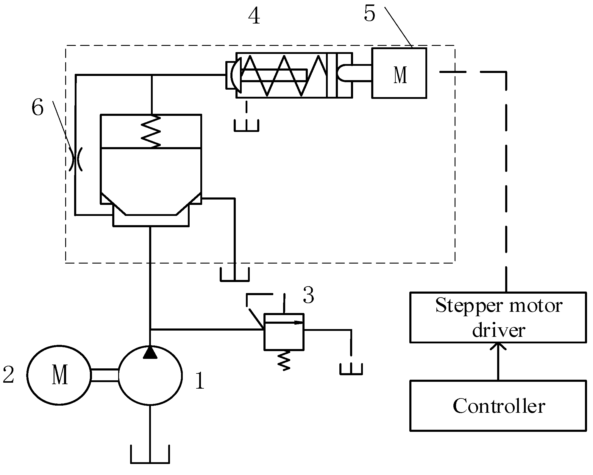
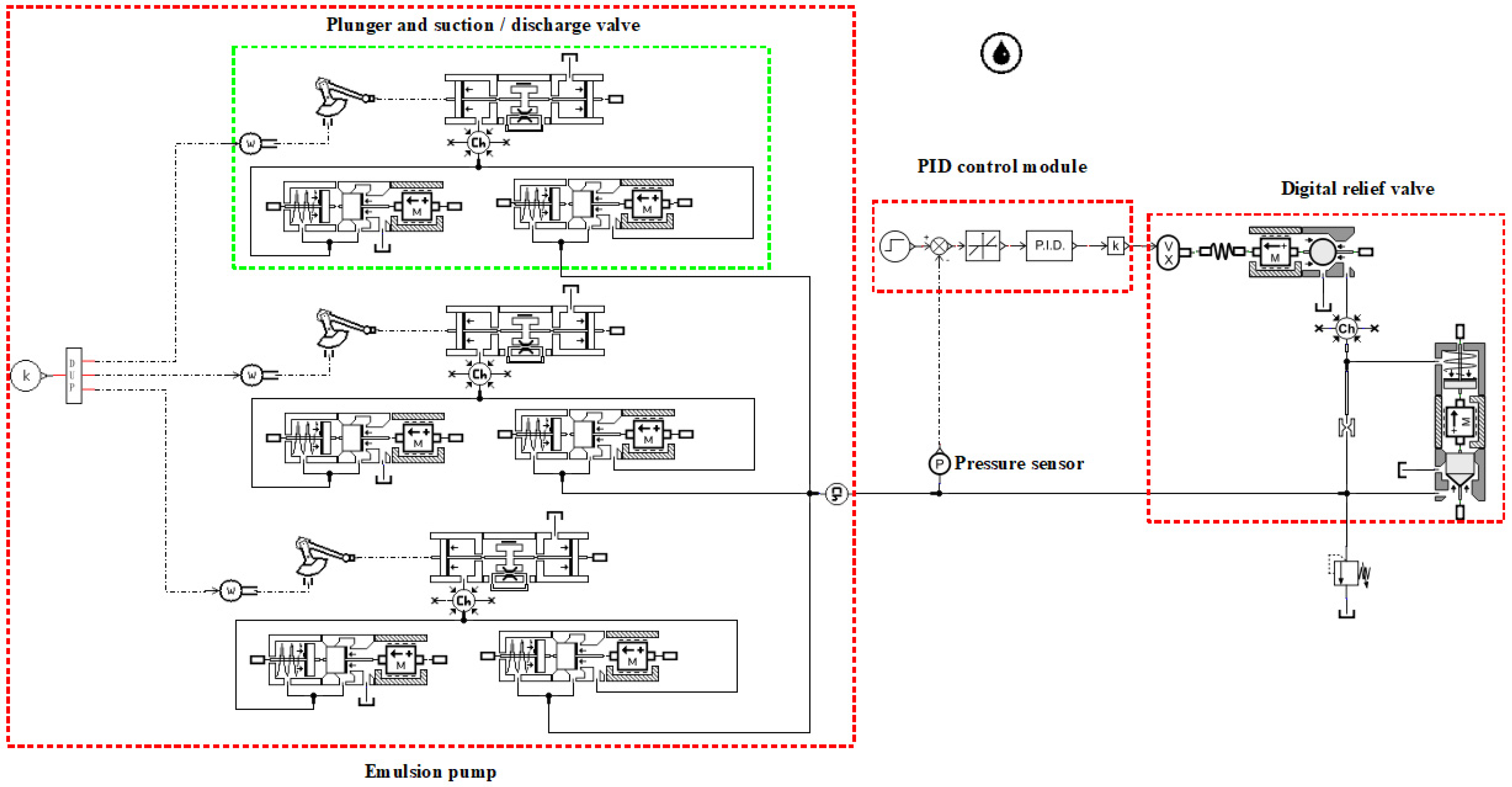
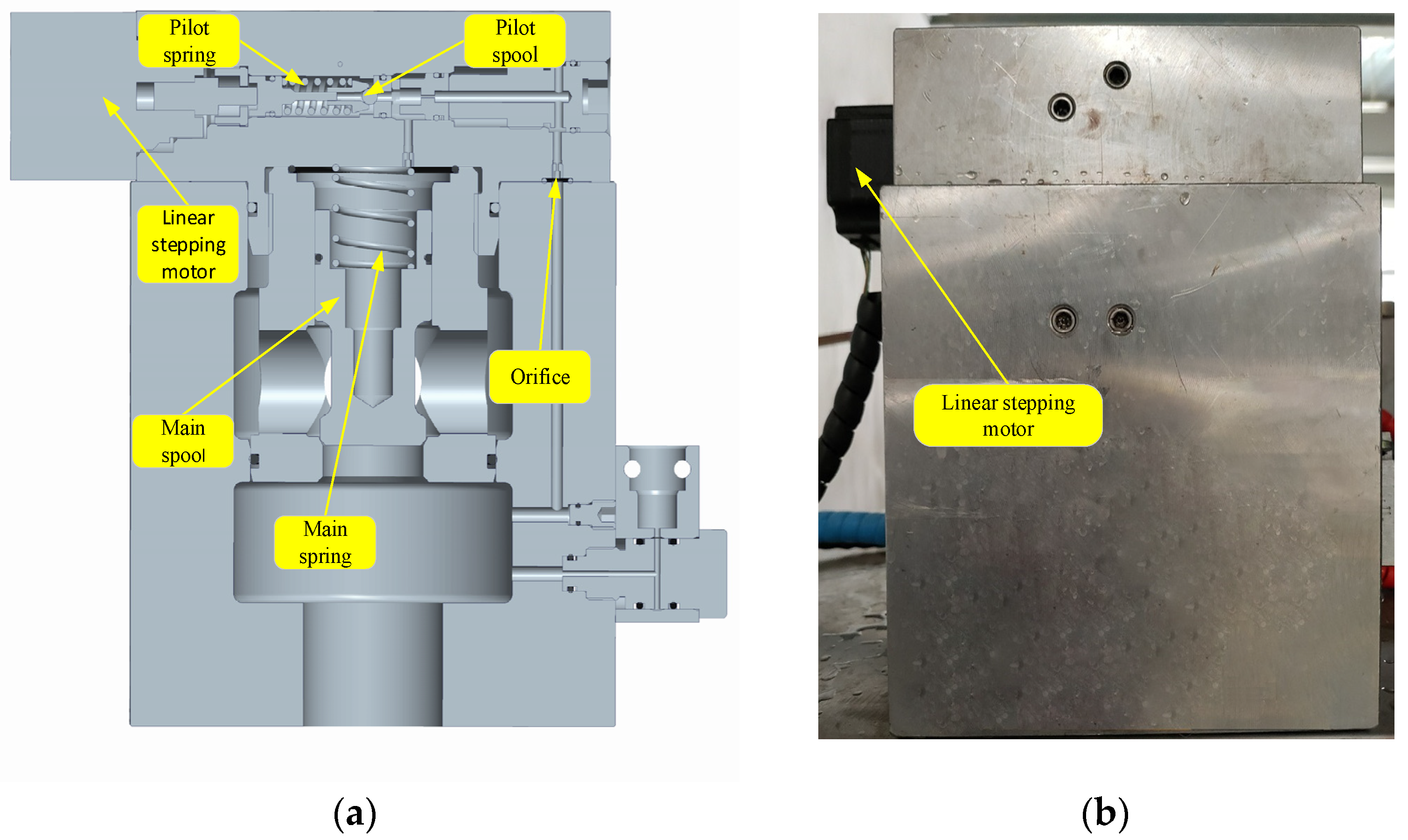
2. Modeling and Pressure Flow Characteristic Analysis of Digital Overflow Valve Loading Hydraulic System

Figure 1 shows the schematic of a hydraulic loading system with a digital relief valve as the pressure regulating device. The digital relief valve is directly connected to the outlet of the tested pump, and the flow of the tested pump is completely discharged through the valve. The digital relief valve uses a fixed-shaft linear stepping motor in place of the adjusting knob used in the manual pilot relief valve. By controlling the stepping motor driver through the controller, the motor shaft can be directly controlled to perform linear movements, and the compression of the pilot valve spring can be directly adjusted to control the system pressure. The linear stepping motor has a small volume and large thrust, which can greatly optimize the structure of the digital relief valve and reduce the volume.

2.1. Mathematical Model for Digital Relief Valve

The relationship between the axis displacement of the linear stepper motor and the number of pulses of the stepper motor driver used for a digital relief valve can be expressed as:
x = 360 β · z · n · l
where x is the shaft extension of the stepping motor, β is the intrinsic stepping angle of the stepper motor, n is the number of pulses, z is the stepper motor subdivision multiplier, and l is the stepper motor lead.
The force balance of the pilot spool can be expressed as:
p 1 A 1 = m 1 d 2 x 1 d t + k 1 ( x + x 1 ) + F b s 1 + f 1 d x 1 d t
where p 1 is the pilot spool inlet pressure, A 1 is the pilot spool action area, m 1 is the pilot spool mass, x 1 is the pilot spool displacement, k 1 is the pilot spring stiffness, F b s 1 is the steady-state hydrodynamic force, and f 1 is the pilot spool viscous damping factor.
The steady-state hydrodynamic force of the pilot spool, F b s 1 , can be calculated from the following equation:
F b s 1 = 2 π · d 1 · p 1 · C d 1 · C v · x 1 · c o s φ
where d 1 is the pilot spool diameter, C d 1 is the flow coefficient at the pilot spool, C v is the velocity coefficient of the small bore, and φ is the half cone angle of the pilot spool.
The balance of forces on the main spool can be expressed as:
p 2 A 2 p 1 A 3 = m 2 d 2 x 2 d t + k 2 ( x 2 + x 0 ) + m 2 g + F b s 2 + f 2 d x 2 d t
where p 2 is the inlet pressure at the main spool, A 2 is the area of the lower chamber of the main spool, A 3 is the cross-sectional area of the upper chamber of the main spool, m 2 is the spool mass, x 2 is the spool displacement, k 2 is the stiffness of the main valve spring, x 0 is the initial compression of the main valve spring, F b s 2 is the steady-state hydrodynamic force of the main spool, g is gravitational acceleration, and f 2 is the viscous damping factor of the main spool.
The steady-state hydrodynamic force, F b s 2 , of the main spool can be calculated from the following equation:
F b s 2 = 2 π · d 2 · p 2 · C d 2 · C v · x 2 · c o s θ
where d 2 is the main spool diameter, C d 2 is the flow coefficient at the main spool, and θ is the half cone angle of the main spool.
The continuity equation of the main valve port flow can be expressed as:
Q 2 = C d 2 · π · d m · x 2 · s i n θ · 2 p 2 ρ
where Q 2 is the flow rate at the main spool, d m is the diameter of the main valve bore, and ρ is the density of the hydraulic oil.
The continuity equation of the pilot valve port flow can be expressed as:
Q 1 = C d 1 · π · d n · x 1 · s i n φ · 2 p 1 ρ
where Q 1 is the flow rate at the pilot valve spool and d n is the diameter of the pilot valve bore.
The flow equation for an emulsion pump can be expressed as:
Q = Q 1 + Q 2
where Q is the emulsion pump flow rate.
Judging from the mathematical model, the pressure regulating system based on a digital relief valve is relatively complex. Because the pilot spool diameter and orifice diameter of the pilot relief valve are relatively small, the flow at the pilot stage is very small. For convenience of calculation, it is generally considered that the opening pressure of the pilot spool is related only to the compression of the pilot spring. Neglecting the influence of the steady-state hydrodynamic force, friction force, opening of the pilot spool valve, and variation in the valve opening, Equation (2) can be simplified as:
p 1 A 1 = k 1 x
The friction force and quality of the main spool can also be ignored. Hence, owing to the large diameter of the main spool, the steady-state hydrodynamic force cannot be ignored. In addition, because the flow of the pump being tested is constant, it can be considered that the main spool is in a stable state. Ignoring the influence of the change in the position of the spool, Equation (3) can be simplified as:
p 2 A 2 p 1 A 3 = k 2 ( x 2 + x 0 ) + F b s 2
Combining the equations eventually yields the following equation:
p 2 A 2 p 2 1 2 f h Q 2 f n p 2 1 2 k 2 Q 2 f n = k 2 x 0 + A 3 k 1 A 1 x
where f h = 2 π · d 2 · C d 2 · C v · c o s θ and f n = C d 2 · π · d m · s i n θ · 2 ρ .
It can be seen from the formula that the mathematical model of the digital relief valve is relatively complex. If the inlet pressure of the digital relief valve is taken as the dependent variable, the independent variables of the system are mainly the extension of the linear motor and flow at the main spool. Owing to the above assumptions, the flow at the main valve core is essentially the same as the flow of the pump being tested. Owing to the complexity of the mathematical model, it is necessary to establish a simulation model of the hydraulic system to further analyze the characteristics of the system.

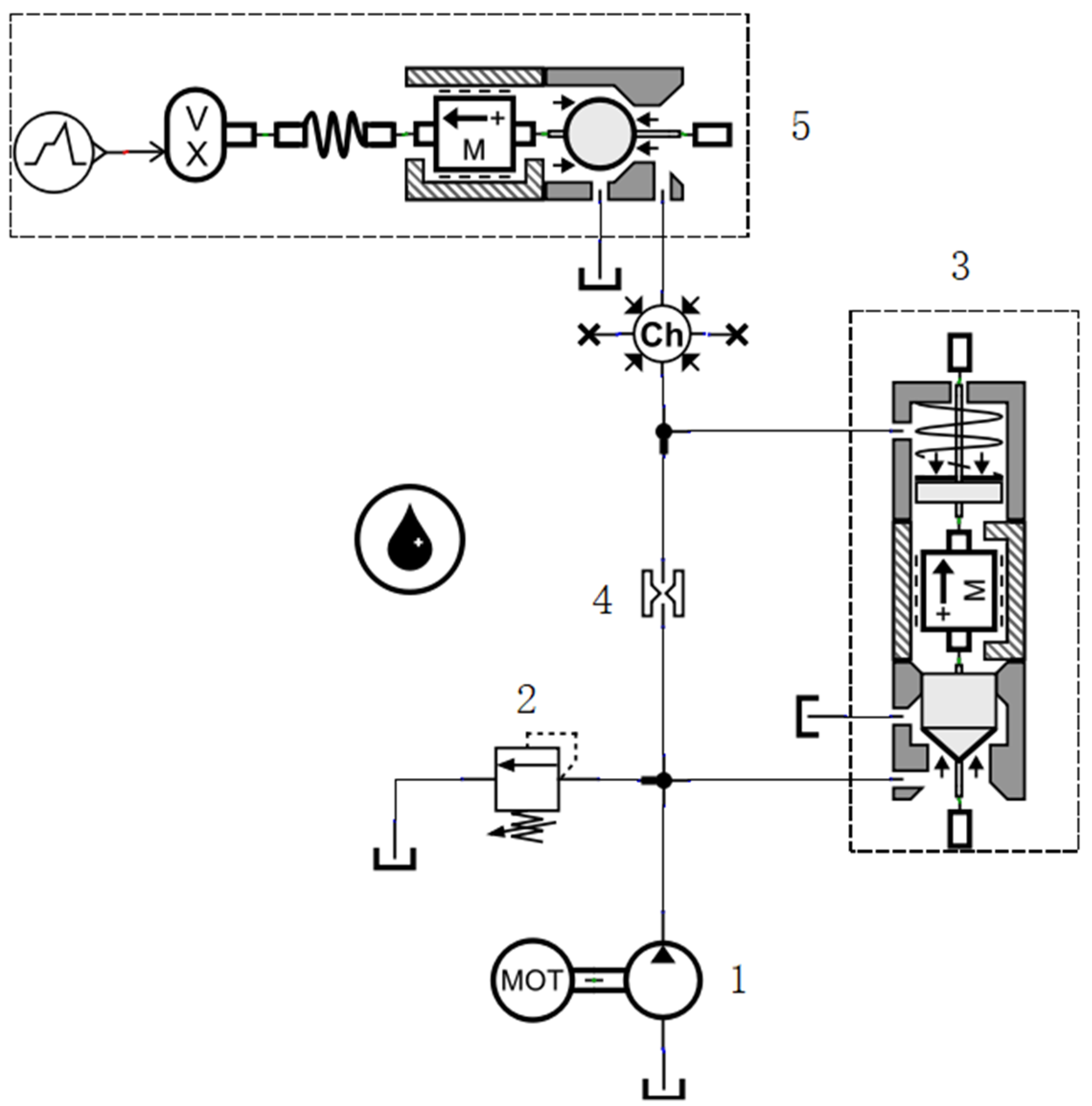
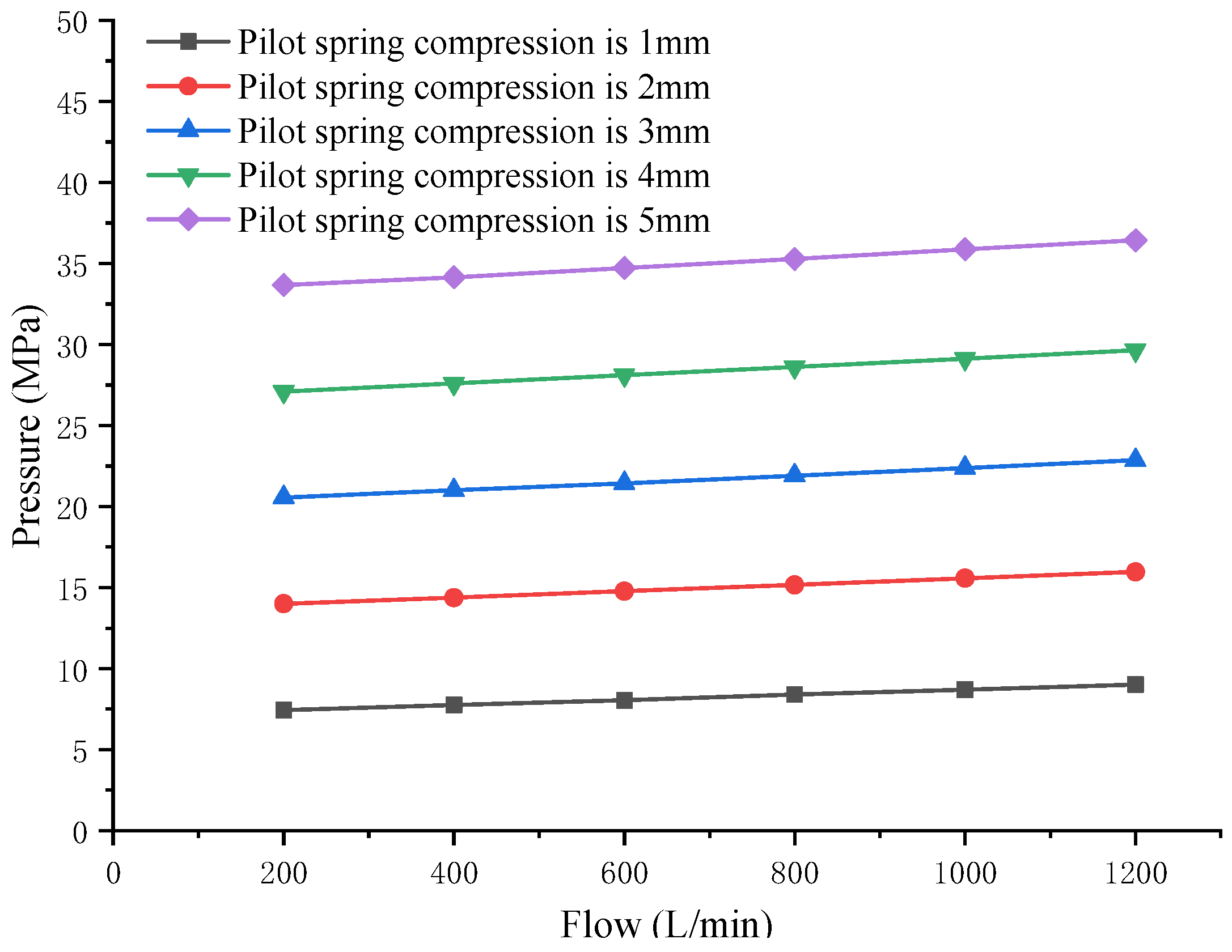
2.2. Hydraulic System Simulation and Analysis

Before the simulation, the key dimensions of the digital relief valve must be determined. Extensive research has been conducted on the influence of various dimensional parameters on the performance of the relief valve. The research results show that when the parameters of the main spool and pilot spool are determined, the parameters such as orifice diameter and spring stiffness of the pilot valve have a significant effect on the characteristics of the relief valve [11,12,13]. In addition, based on the actual working conditions and technical parameters of the tested pump, such as nominal flow and nominal pressure, and considering that the maximum thrust of the selected linear stepping motor is approximately 900 N, the main parameters of the digital relief valve were finally determined, as shown in Table 1.
Based on the size of each part of the digital relief valve, this study developed a system simulation model using AMESim, as shown in Figure 2, to effectively study the influence of the shaft extension of the linear stepping motor and flow of the tested pump on the working pressure of the digital relief valve.
The parameters of the digital relief valve in the simulation model were set according to Table 1. The flow of the tested pump was successively set to 200 L/min, 400 L/min, 600 L/min, 800 L/min, 1000 L/min, and 1200 L/min. Considering the influence of the expansion and contraction of the linear stepper motor shaft, the compression of the pilot spring was set to 1 mm, 2 mm, 3 mm, and 4 mm, and the simulation model was batch processed. The variation curves of the working pressure of the digital relief valve were obtained under various shaft extensions of the linear motor and various flows. The simulation results are shown in Figure 3.
The simulation curves show that, under the same flow, the working pressure of the digital relief valve increases with an increase in the compression of the pilot spring. Moreover, for the same amount of compression of the pilot spring, the displacement of the tested pump has a significant effect on its working pressure. The larger the pump displacement, the higher the working pressure of the digital relief valve, which is consistent with the previous analysis of the hydraulic system using the mathematical model.

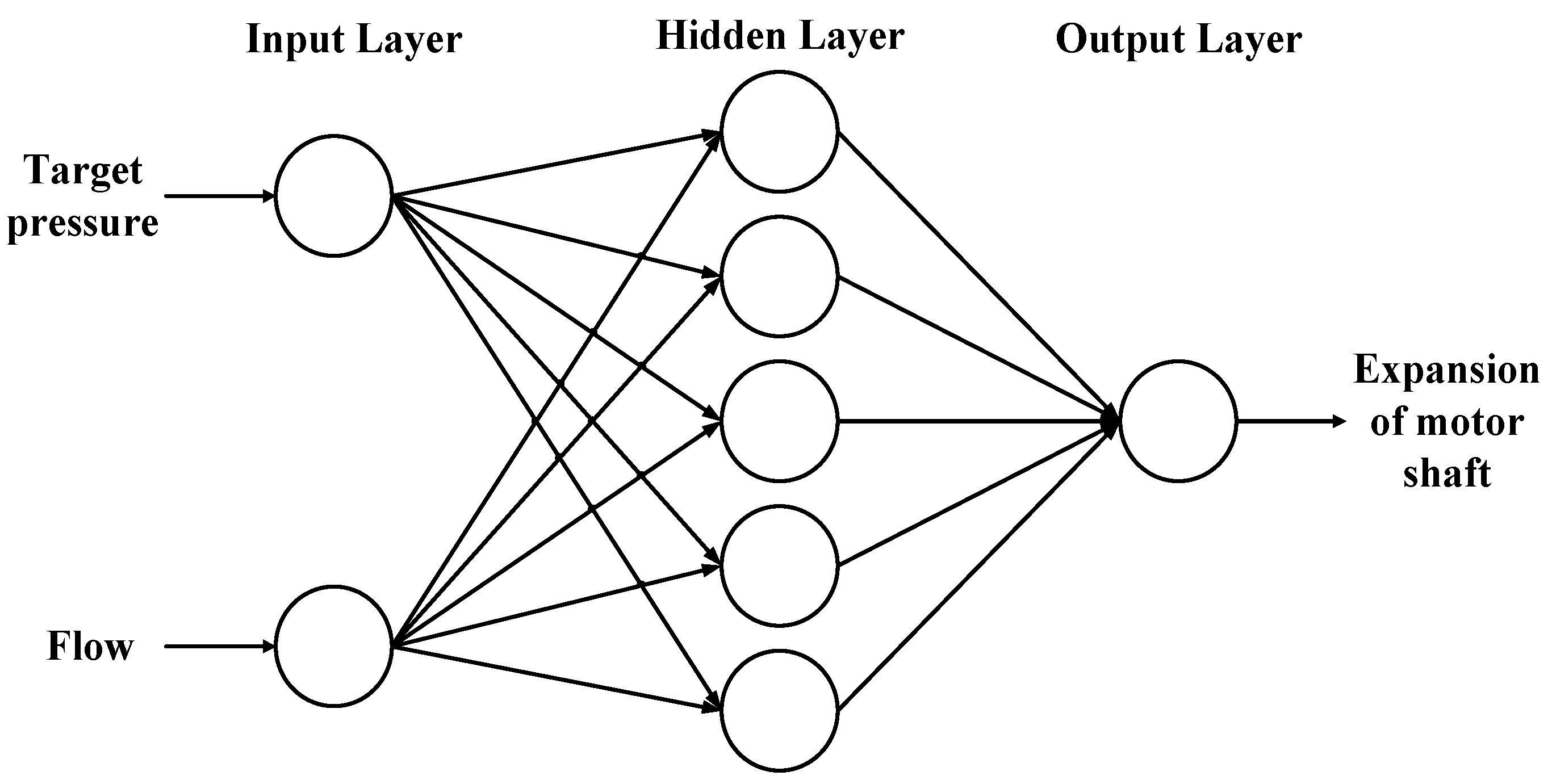
3. Research on Pressure Control Algorithm Based on BP Neural Network

3.1. Selection of Control Algorithm

Based on the analysis of the mathematical and simulation models, the system can be described as a mathematical model with the linear motor shaft extension and pump displacement as independent variables and digital relief valve working pressure as the dependent variable. When the stepping motor shaft extension and pump displacement are known, the working pressure of the digital relief valve can be uniquely determined. To realize the accurate adjustment of the system pressure, the functional relationship between the three variables should be established. Because the target pressure is a known quantity, and the flow of the tested pump is very easy to measure, the functional relationship between them can be specified, following which the extension of the linear stepping motor shaft can be calculated. The stepping motor has very high control accuracy, owing to which the motor shaft can be more accurately adjusted to the target position. Thus, the working pressure of the digital relief valve can be accurately controlled.
With the development of data processing and function fitting, ANNs have evolved rapidly in recent years and have a very wide range of applications. It has been proven that neural networks can, in theory, fit any nonlinear function [14], and can deal with the complex nonlinear relationship between the input and output in many fields. The multilayer BP neural network encompasses a very wide range of ANNs. The application of neural networks in various fields has been extensively researched. Li et al. [15] studied the relationship between the output frequency difference data and corresponding loading pressure in a surface acoustic wave micro-pressure sensor. A BP neural network was trained with experimental data to predict the output pressure of the sensor using the frequency difference as the input. Song et al. [16] used a BP neural network to retrieve the extinction coefficient from the Mie scattering signal of LIDAR, and designed the structure and main parameters of the BP network according to the practical application. The BP network was then trained with the Mie scattering signal and extinction coefficient retrieved using the Raman method. The trained BP network was then used to retrieve the extinction coefficient from the Mie scattering signal under different conditions.
Obviously, the above successful applications of function fitting based on the BP neural network in other fields indirectly suggest the feasibility of developing an algorithm for regulating the emulsion pump test pressure based on a digital relief valve and BP neural network.

3.2. Simulation of Control Algorithm

The analytical steps of the ANN are generally uniform and include the following: (1) collect the data, (2) define the neural network structure and parameter, (3) train and validate the model [17]. To further verify the feasibility of the algorithm, the neural network was designed based on the AMESim simulation data and simulated according to the above steps.

3.2.1. Data Collection

To obtain more effective results, the nominal flow of the tested pump was set to 200 L/min, 400 L/min, 600 L/min, 800 L/min, 1000 L/min, and 1200 L/min in the AMESim model according to the actual operating conditions of the emulsion pump. The extension of the linear stepper motor shaft was then varied from 0 to 5 mm with a gradient of 0.05 mm, and the AMESim simulation model was batch processed. The pressures (66 values) under various working conditions were recorded, as shown in Table 2.

3.2.2. Definition of Neural Network Structure and Parameter

According to the above analysis of the test system, the input layer of the BP neural network contains two inputs: pressure and flow. The output layer contains one output: shaft extension of the linear stepping motor. The number of hidden layers was set to one according to the empirical formula, and the number of hidden layer neurons was determined as five according to the Kolmogorov theorem. The BP neural network model was then established, as shown in Figure 4.
A suitable activation function should be selected based on the network model. The activation function between the input and hidden layers was set to “tansig”, and the activation function between the hidden and output layers was set to “purelin”.

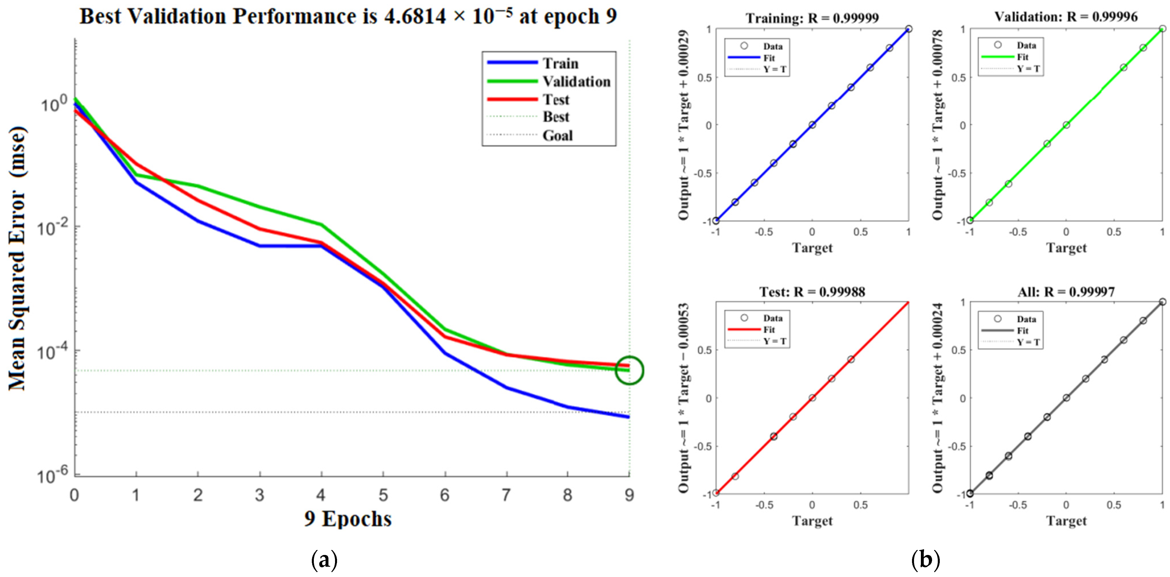
3.2.3. Training and Validation of the Model

The BP neural network model was developed in MATLAB according to the above configuration. The maximum number of trainings was set to 1000, learning rate was set to 0.01, and minimum error of the training target was set to 0.0001. To improve the reliability of training, 60 sample data were randomly selected as the training data, and the remaining 6 data were used as the validation data. The performance curve of the model error and its regression curve are shown in Figure 5. It can be seen from Figure 5 that the best training result was achieved after nine iterations. In addition, it can be seen from Figure 5 that the prediction accuracy of this model reached 0.99997. The above results show that the BP neural network can accurately perform the prediction.

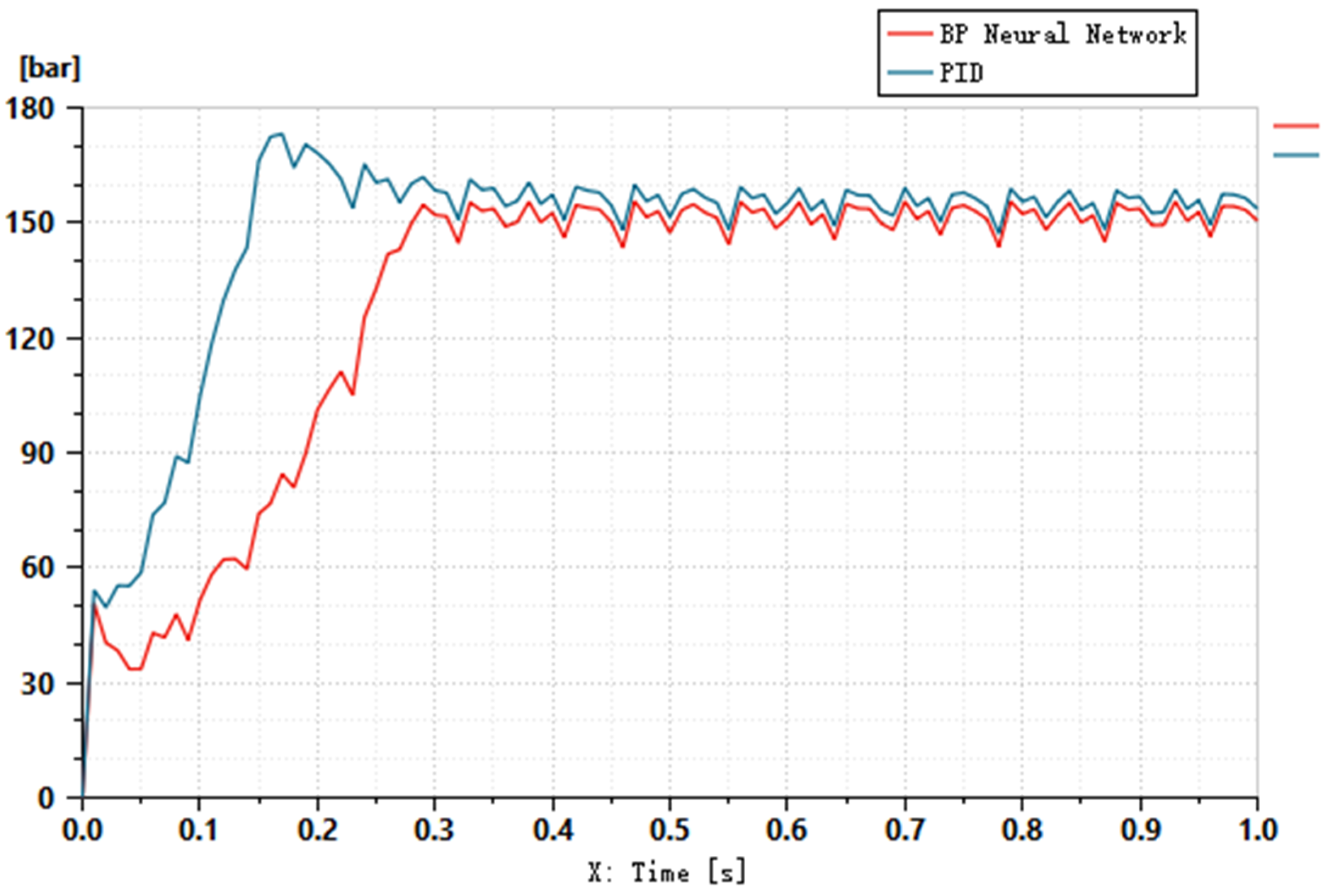
3.2.4. Simulation and Comparison of Control Algorithms

In order to further verify the progressiveness and reliability of the control algorithm based on a BP neural network, the algorithm is compared with the traditional PID algorithm. An emulsion pump with a theoretical flow rate of 517 L/min is chose as the test pump, and the target pressure is set to 15 MPa.
Firstly, the PID simulation model of the emulsion pump loading test system based on a digital relief valve is established by AMESim, as shown in Figure 6. At the same time, in order to reflect the influence of the flow pulsation of the emulsion pump on the control algorithm, a detailed model of the emulsion pump is established in the simulation model, and a dead zone is set for the PID algorithm. The main technical parameters of the hydraulic system are shown in Table 3. The technical parameters of the digital relief valve are consistent with Table 2, and the proportional coefficient (KP), integral coefficient (Ki) and derivative coefficient (KD) of the PID control algorithm are set to 3, 0.02, and 0.003, respectively.
Secondly, according to the trained BP neural network model, the shaft extension of the stepping motor is predicted to be 2.054 mm. Considering the characteristics of the stepping motor, the action time of the linear stepping motor shaft is set to 0.2 s in the simulation model. The comparison effect of the two algorithms is shown in Figure 7.
The simulation results show that the overshoot of the PID control algorithm is approximately 17%, and for the BP neural network control algorithm, the system pressure oscillates up and down around the target pressure, which is also the inherent property of the hydraulic system. The adjustment time of the PID algorithm and control algorithm based on a BP neural network are basically the same, but the pressure of the PID algorithm is greater than that of the target. Through comparison, it is obvious that the control algorithm has better control accuracy and less pressure overshoot than the PID algorithm.

4. Experiment and Discussion

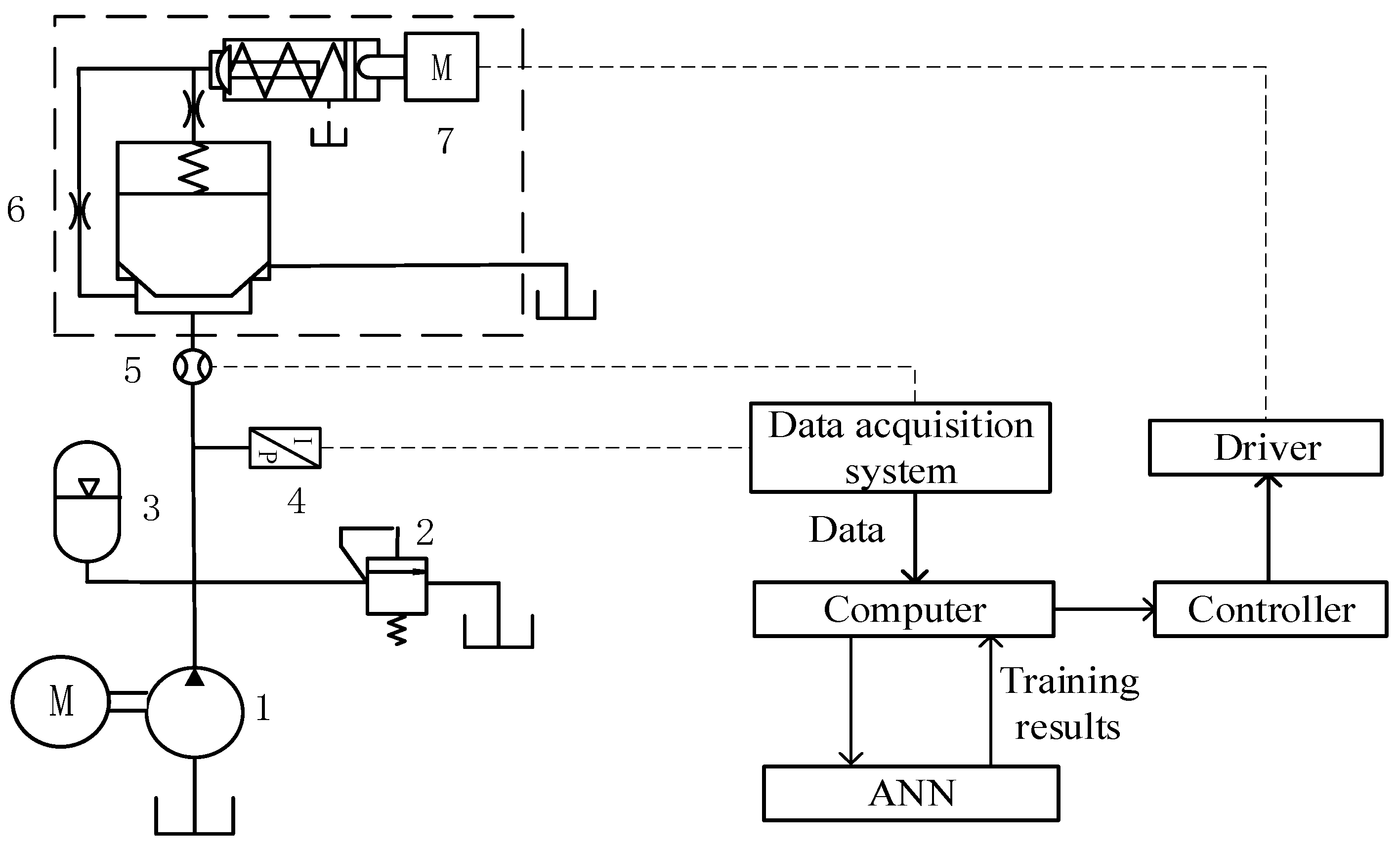
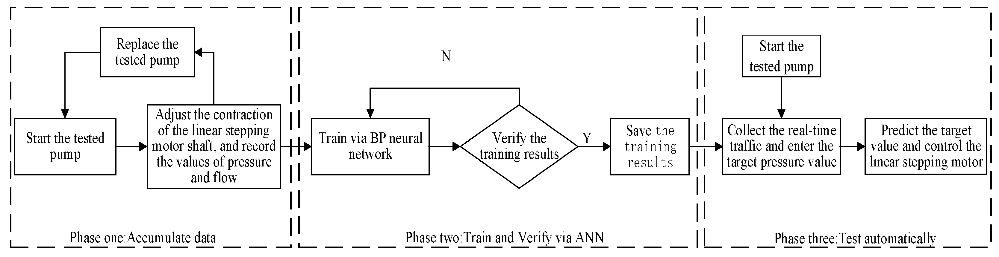
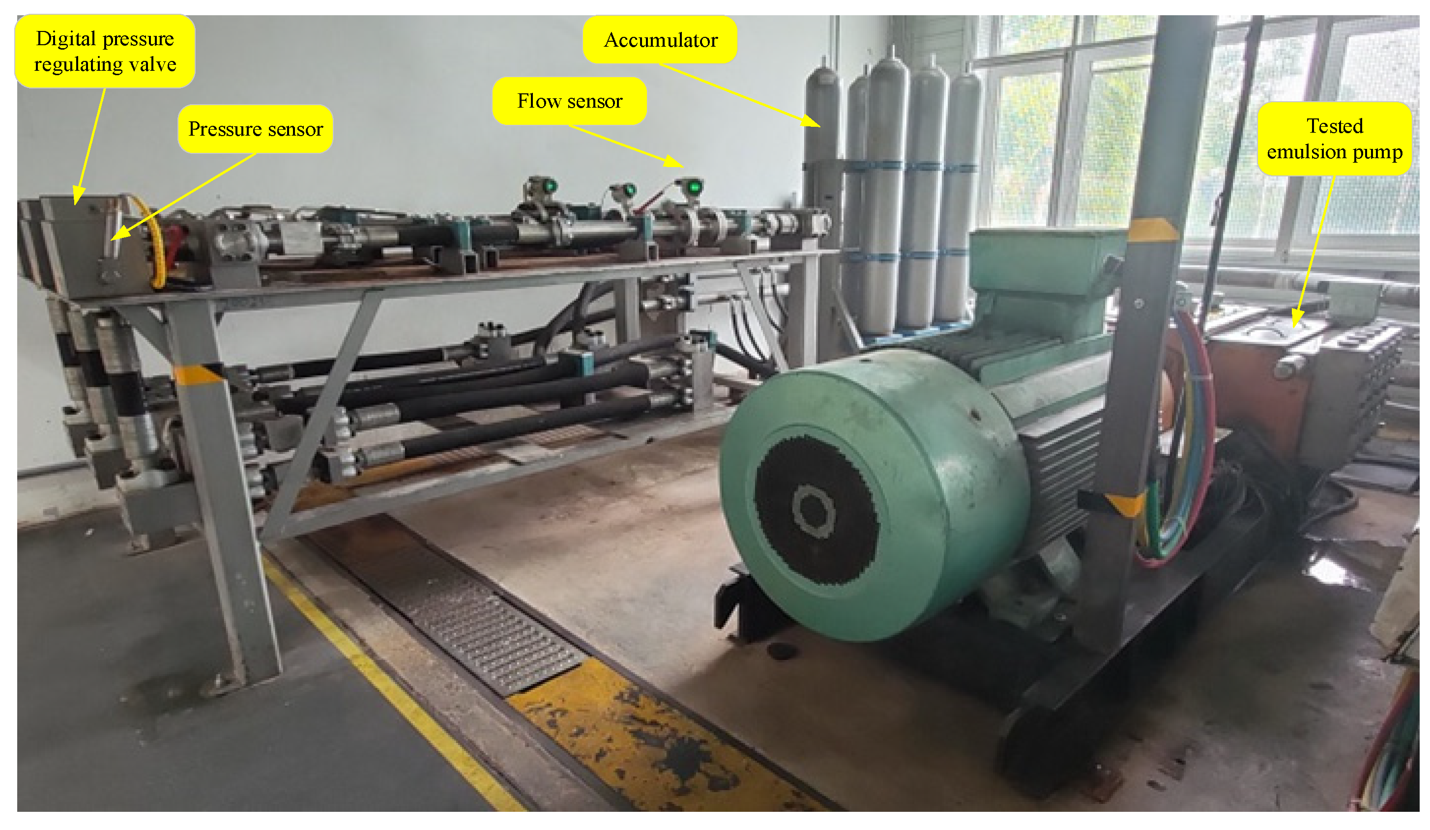
4.1. Development of Test Platform and Test Process

Based on the above analysis of the hydraulic system and control algorithm, this paper proposes a test system based on the principle shown in Figure 8. The hydraulic system of this test platform mainly includes the tested pump, digital relief valve, accumulator, and safety valve. The digital relief valve is directly connected to the outlet of the tested pump to regulate its outlet pressure. The outlet of the tested pump is connected with an accumulator and a safety valve, which are responsible for pressure stabilization and protection, respectively. The sensor system mainly includes a pressure sensor and flow sensor. The pressure sensor is installed at the pump outlet to monitor the outlet pressure of the tested pump. The flow sensor is responsible for monitoring the flow of the tested pump. The data collected by each sensor are transmitted to the computer for storage through the data acquisition system, and the prediction is made after the training of the ANN. Finally, according to the prediction results, the computer controls the linear stepping motor of the digital relief valve through the driver and achieves the purpose of adjusting the outlet pressure of the pump being tested.
The testing process was divided into three main stages, as shown in Figure 9. The first is the data accumulation stage. In this stage, the upper computer and driver controlled the shaft of the linear stepping motor to achieve different extension lengths, thus adjusting the outlet pressure of the tested pump; the pressure and flow values during this process were recorded. The tested pump was then replaced with a pump having a different flow, and the above steps were repeated.
The second stage was the training and verification of the sample data through the ANN. The samples were divided into the training set and the verification set according to a certain proportion, and a suitable neural network model was designed for training and verification.
The last stage was the automatic testing stage. The training results were saved and files were generated, which could be called and executed by the upper computer. The target pressure value was then input through the upper computer, and the expansion and contraction of the linear stepping motor shaft were predicted online. Finally, the digital overflow valve was controlled by the controller according to the prediction results to realize the intelligent control of the tested pump pressure.
Based on the above activities, the development of the digital relief valve and test bench were finally completed, as shown in Figure 10 and Figure 11.

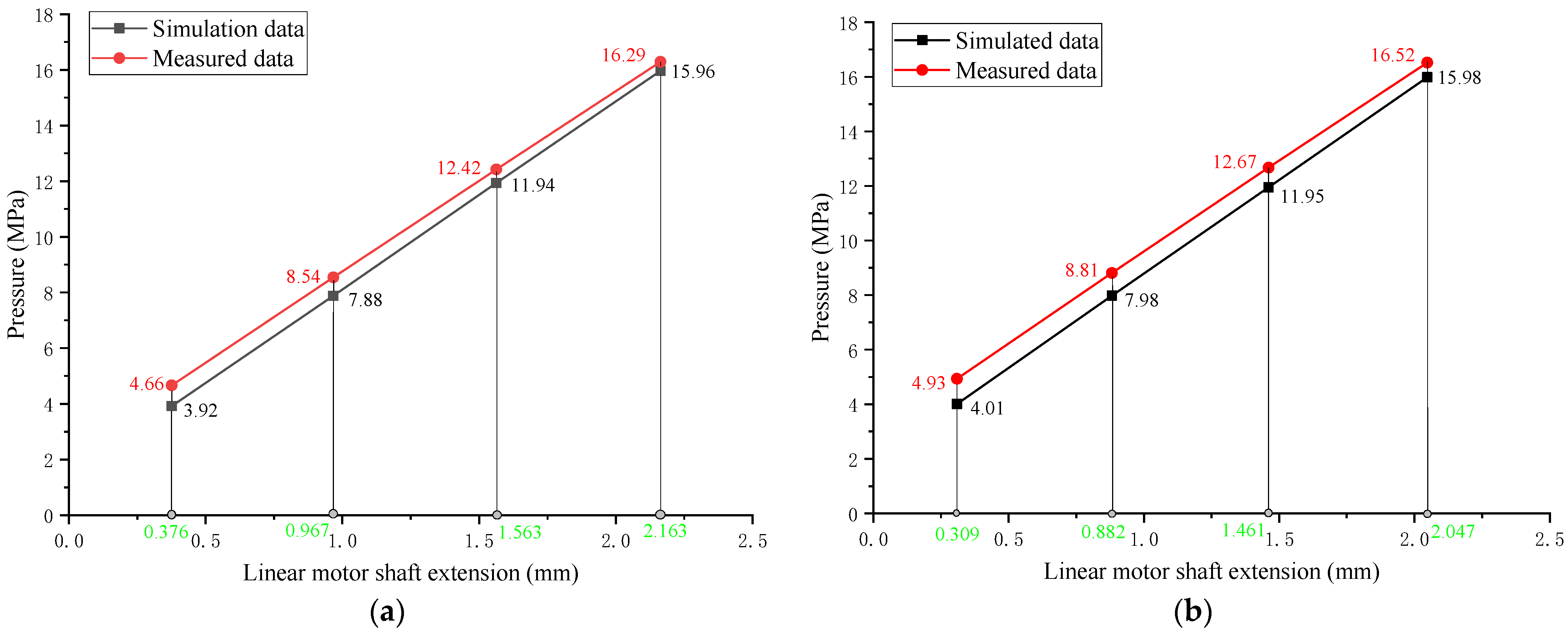
4.2. Test Results and Analysis
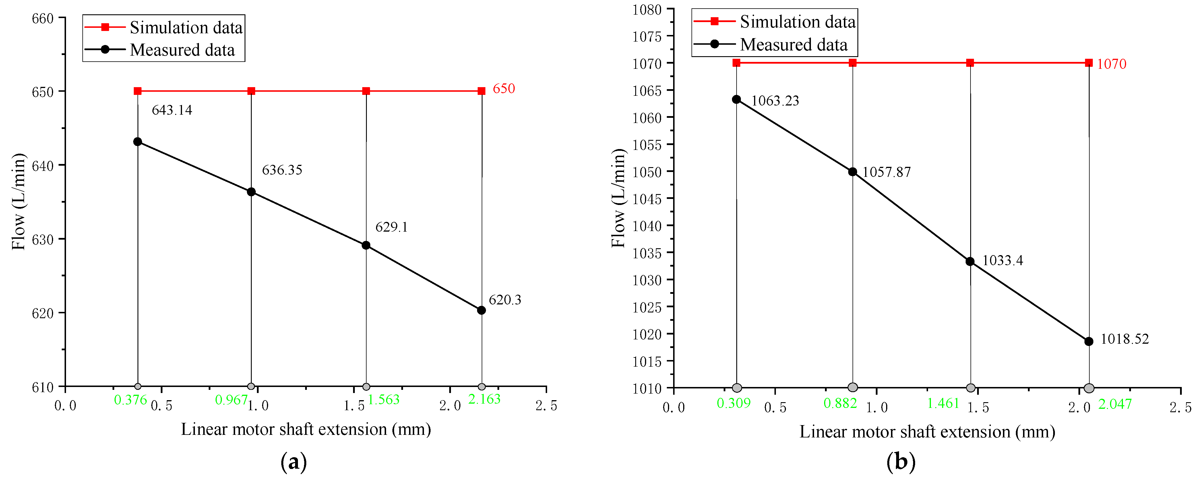
Owing to the limitations of the laboratory, the testing was performed using only two emulsion pumps, one with a theoretical flow of 650 L/min and nominal pressure of 37.5 MPa, and the other with a theoretical flow of 1070 L/min and nominal pressure of 16 MPa. Owing to the small number of samples of the tested pump, the test could not be carried out entirely according to the test process described above. Because the digital relief valve was designed and manufactured according to the simulation parameters, the above training results based on the simulation data were directly used in this study. The theoretical flow of the tested pump was the input flow, and the target pressure values were set to 4 MPa, 8 MPa, 12 MPa, and 16 MPa. On this basis, the projections of the linear stepper motor shafts of the two tested pumps were predicted for each target pressure. The prediction results are shown in Table 4.
Taking the predicted data as the target values, the linear stepping motor was controlled to move to the target position on the AMESim simulation model and actual test platform, and the pressure and flow parameters of the tested pump were recorded. The test results are shown in Figure 12 and Figure 13.
It can be deduced from the pressure curves in Figure 12 that, under the same target pressure, the larger the flow of the tested pump, the smaller the extension of the motor shaft, which is consistent with the simulation results. In the AMESim simulation model, the pressure of the tested pump is very close to the target pressure, and the maximum error is only 2%. However, a certain difference is observed between the target and measured values. For the same shaft extension of the linear stepper motor, the actual monitoring data of the pressure are greater than the target data, and the greater the flow, the greater the difference. In addition, with a continuous increase in the extension of the linear stepper motor, the change trend of the measured pressure data is slightly slower than that of the simulation data. Based on the specific working conditions, this difference can be attributed to the following:
(1)
The resistance loss caused by the hydraulic pipeline and other structures of the test system causes the actual pressure value to be higher than the predicted pressure, and the greater the flow of the tested pump, the greater the resistance loss.
(2)
The volumetric efficiency of the emulsion pump is not constant; it decreases with the increase in pressure, which can be clearly deduced from Figure 13. However, the shaft extension of the linear stepping motor is predicted according to the theoretical flow, which affects the prediction accuracy to a certain extent.

5. Conclusions

This paper proposed a novel method for the automatic loading test of mining emulsion pumps by applying a digital relief valve with a linear stepping motor as the driving device. The new method is more suitable for high-pressure and large-flow conditions than the traditional loading test method of a hydraulic pump, and can realize remote control and improved the safety of the test process. Based on the simulation of the hydraulic system, an intelligent control method for the system pressure based on a BP neural network was proposed. Compared with the traditional PID control algorithm, the BP neural network control algorithm has better control accuracy and less pressure overshoot. Finally, a digital relief valve was designed, and a test platform was constructed. The feasibility of the emulsion pump loading test method based on a digital relief valve and BP neural network control algorithm was verified through experiments. In the future, we need to increase the number of tested emulsion pumps and accumulate a greater amount of data, which can be used to train the BP neural network to improve the accuracy of the intelligent control algorithm. Furthermore, the method proposed in this paper is applicable to the loading test of not only the mining emulsion pump but also other types of hydraulic pumps. It can be especially utilized for testing pumps with a wide range of flow levels.

Author Contributions

Conceptualization, J.T. and W.L.; methodology, W.L.; software, H.W.; validation, J.T. and H.W.; formal analysis, W.L.; investigation, W.L.; resources, J.T.; data curation, W.L.; writing—original draft preparation, W.L.; writing—review and editing, W.L.; visualization, W.L.; supervision, H.W.; project administration, J.T.; funding acquisition, J.T. All authors have read and agreed to the published version of the manuscript.

Funding

This work was supported by the Fundamental Research Funds for the Central Universities under Grant 2022JCCXJD02 and 2022YJSJD09 and was also supported by the Open Research Fund of Key Laboratory of Nondestructive Testing (Nanchang Hangkong University), Ministry of Education (EW202180222), the National Natural Science Foundation of China, under Grant 51774293.

Data Availability Statement

Not applicable.

Acknowledgments

The authors appreciate the fiscal encouragement from the Fundamental Research Funds for the Central Universities under grants 2022JCCXJD02 and 2022YJSJD09, the Open Research Fund of Key Laboratory of Nondestructive Testing (Nanchang Hangkong University), Ministry of Education (EW202180222), and the National Natural Science Foundation of China under grant 51774293.

Conflicts of Interest

The authors declare no conflict of interest.

References

  1. Wang, Y.X.; Li, Y.J.; Yang, H.; Xu, Z.L. Super-wetting, photoactive TiO2 coating on amino-silane modified PAN nanofiber membranes for high efficient oil-water emulsion separation application. J. Membr. Sci. 2019, 580, 40–48. [Google Scholar] [CrossRef]
  2. Nuanlaor, K.; Chatchai, P. Photoelectrocatalytic reactor improvement towards oil-in-water emulsion degradation. J. Environ. Manag. 2020, 279, 111568. [Google Scholar]
  3. Zhou, R.; Meng, L.; Yuan, X.; Qiao, Z. Research and Experimental Analysis of Hydraulic Cylinder Position Control Mechanism Based on Pressure Detection. Machines 2022, 10, 1. [Google Scholar] [CrossRef]
  4. Li, R.; Wang, D.L.; Wei, W.S.; Li, S.B. Analysis of the Movement Characteristics of the Pump Valve of the Mine Emulsion Pump Based on the Internet of Things and Cellular Automata. Mob. Inf. Syst. 2021, 2021, 8. [Google Scholar] [CrossRef]
  5. Huang, Z.H.; Gao, H.W.; Xie, Y. Hybrid Excavator Test Bed Hydraulic Load System Design. Adv. Mater. Res. 2012, 605–607, 1322–1325. [Google Scholar] [CrossRef]
  6. Zhang, C.; Zhao, S.H.; Guo, G.; Dong, W.K. Modeling and Simulation of Emulsion Pump Station Pressure Control System Based on Electro-Hydraulic Proportional Relief Valve. Appl. Mech. Mater. 2012, 190–191, 860–864. [Google Scholar] [CrossRef]
  7. Song, E.Z.; Zhao, G.F.; Yao, C.; Ma, Z.K.; Ding, S.L.; Ma, X.Z. Study of Nonlinear Characteristics and Model Based Control for Proportional Electromagnet. Math. Probl. Eng. 2018, 2018, 2549456. [Google Scholar] [CrossRef]
  8. Wang, X.Z.; Chen, F.X.; Zhu, R.F.; Huang, X.L.; Sang, N.; Yang, G.L.; Zhang, C. A Review on Disturbance Analysis and Suppression for Permanent Magnet Linear Synchronous Motor. Actuators 2021, 10, 77. [Google Scholar] [CrossRef]
  9. Jia, T.C.; Wu, Z.Y.; Wang, J.; Feng, R.G.; Qin, Y.J. Design and Performance Analysis of Digital Pressure Relief Valve of Water-Based Hydraulic. Appl. Mech. Mater. 2013, 387, 369–373. [Google Scholar] [CrossRef]
  10. Zeng, Q.L.; Tian, M.Q.; Wan, L.Y.; Dai, H.Z.; Yang, Y.; Sun, Z.Y.; Lu, Y.J.; Liu, F.Q. Characteristic Analysis of Digital Large Flow Emulsion Relief Valve. Math. Probl. Eng. 2020, 2020, 5820812. [Google Scholar] [CrossRef]
  11. Wan, L.R.; Dai, H.Z.; Zeng, Q.L.; Lu, Z.G.; Sun, Z.Y.; Tian, M.Q.; Lu, Y.J. Characteristic Analysis of Digital Emulsion Relief Valve Based on the Hydraulic Loading System. Shock Vib. 2020, 2020, 8866919. [Google Scholar] [CrossRef]
  12. Dasgupta, K.; Karmakar, R. Dynamic analysis of pilot operated pressure relief valve. Simul. Model. Pract. Theory 2002, 10, 35–49. [Google Scholar] [CrossRef]
  13. Yuan, X.J.; Guo, K.H. Modelling and analysis for a pilot relief valve using CFD method and deformation theory of thin plates. Sci. China Technol. Sci. 2015, 58, 979–998. [Google Scholar] [CrossRef]
  14. Hornik, K.; Stinchcombe, M.B.; White, H. Multilayer feedforward networks are universal approximators. Neural Netw. 1989, 2, 359–366. [Google Scholar] [CrossRef]
  15. Li, Y.Y.; Li, J.T.; Huang, J.; Zhou, H. Fitting Analysis and Research of Measured Data of SAW Micro-pressure Sensor based on BP Neural Network. Measurement 2020, 105, 107533. [Google Scholar] [CrossRef] [PubMed]
  16. Song, Y.H.; Yue, L.Y.; Wang, Y.F.; Di, H.G.; Gao, F.; Li, S.C.; Zhou, Y.D.; Hua, D.X. Research on BP network for retrieving extinction coefficient from Mie scattering signal of lidar. Measurement 2020, 164, 108028. [Google Scholar] [CrossRef]
  17. Wang, W.M.; Sun, H.B.; Guo, J.Q.; Lao, L.Y.; Wu, S.D.; Zhang, J.F. Experimental Study on Water Pipeline Leak Using In-Pipe Acoustic Signal Analysis and Artificial Neural Network Prediction. Measurement 2021, 186, 110094. [Google Scholar] [CrossRef]
Figure 1. Schematic of a digital relief valve driven by a linear stepper motor. 1—Pump being tested; 2—motor; 3—safety valve; 4—digital relief valve; 5—linear stepper motor; 6—damping hole.
Machines 10 00896 g001
Figure 2. AMESim simulation model of a hydraulic system based on a digital relief valve as a pressure regulator. 1—Pump being tested; 2—safety valve; 3—main valve section; 4—pilot spool damping hole; 5—pilot valve section.
Machines 10 00896 g002
Figure 3. Working pressure variation curves of digital relief valve under different spring compressions and flow levels.
Machines 10 00896 g003
Figure 4. Neural network model.
Machines 10 00896 g004
Figure 5. Simulation curve. (a) Performance curves of model error; (b) Regression curves of model error.
Machines 10 00896 g005
Figure 6. PID simulation model.
Machines 10 00896 g006
Figure 7. Comparison curve between PID algorithm and BP neural network algorithm.
Machines 10 00896 g007
Figure 8. Schematic of digital relief valve-based emulsion pump testing system. 1—Pump being tested; 2—safety valve; 3—accumulator; 4—pressure sensor; 5—flow sensor; 6—digital relief valve; 7—linear stepper motor.
Machines 10 00896 g008
Figure 9. Flowchart for emulsion pump testing based on the artificial neural network algorithm.
Machines 10 00896 g009
Figure 10. 3D and physical models of the digital relief valve: (a) 3D model; (b) physical model.
Machines 10 00896 g010
Figure 11. Emulsion pump test platform.
Machines 10 00896 g011
Figure 12. Pressure curves under simulated and actual working conditions: (a) Emulsion pump with theoretical flow of 650 L/min; (b) Emulsion pump with theoretical flow of 1070 L/min.
Machines 10 00896 g012
Figure 13. Flow curves under simulated and actual working conditions: (a) Emulsion pump with theoretical flow of 650 L/min; (b) Emulsion pump with theoretical flow of 1070 L/min.
Machines 10 00896 g013
Table 1. Main parameters of relief valve.
Parameter NameValue
Pilot valve seat diameter (mm)5
Pilot valve spool diameter (mm)5.5
Pilot spring stiffness (mm)100
Pilot valve spool mass (g)8
Pilot valve seat half cone angle (°)20
Coefficient of viscous friction of pilot spool (N/(m/s))100
Diameter of upper chamber of main spool (mm)42
Main spool lower chamber diameter (mm)38
Main spring stiffness (N/mm)20
Damping hole diameter (mm)0.8
Main spool mass (g)100
Main spool half taper angle (°)30
Main spool static friction (N)30
Coefficient of viscous friction of main spool (N/(m/s))400
Initial compression of main spring (mm)10
Table 2. Pressure values for various pump flows and stepper motor shaft extensions.
Flow (L/min)Shaft Extension of Linear Stepping Motor (mm)
00.511.522.533.544.55
Pressure (MPa)
2001.10 4.18 7.44 10.73 14.00 17.27 20.56 23.83 27.10 30.39 33.67
4001.32 4.46 7.75 11.08 14.38 17.71 21.01 24.29 27.60 30.90 34.15
6001.51 4.69 8.04 11.43 14.78 18.09 21.43 24.76 28.10 31.43 34.73
8001.72 4.95 8.39 11.76 15.16 18.54 21.91 25.27 28.61 31.94 35.28
10001.95 5.23 8.69 12.11 15.57 18.95 22.38 25.73 29.13 32.52 35.88
12002.21 5.51 9.01 12.51 15.96 19.39 22.85 26.23 29.64 33.07 36.43
Table 3. Main parameters of the hydraulic system.
Parameter NameValue
Plunger diameter (mm)65
Plunger stroke (mm)105
Suction valve diameter (mm)51
discharge valve diameter (mm)51
Crank speed (rad/min)436
Maximum dead zone value (bar)8
Minimum dead zone value (bar)−8
PID output gain0.0001
Table 4. Prediction of shaft extension of linear stepping motor.
Target Pressure (MPa)Shaft Extension of Linear Stepping Motor (mm)
650 L/min Pump1070 L/min Pump
40.3760.309
80.9670.882
121.5631.461
162.1632.047
Publisher’s Note: MDPI stays neutral with regard to jurisdictional claims in published maps and institutional affiliations.

