Experimental Study and Simulation-Based Criterion for Stamping Skid Line
Abstract
1. Introduction
2. Stamping Experiment Method and Numerical Simulation
2.1. Experimental Method
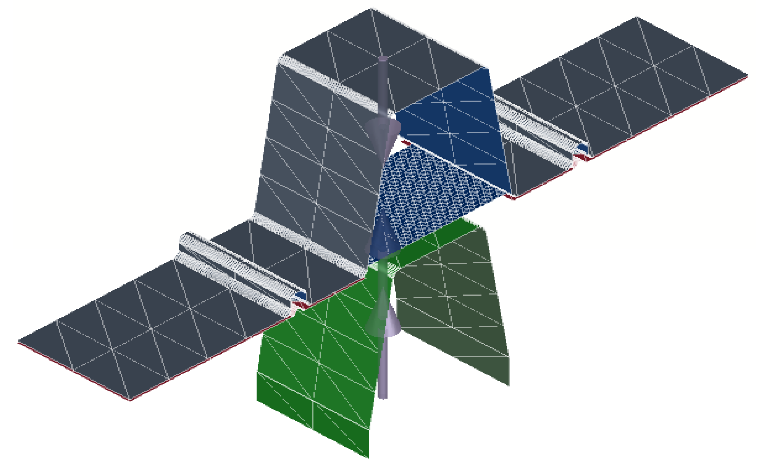
2.2. Numerical Simulation Method
3. Basic Mechanical Properties Experiment
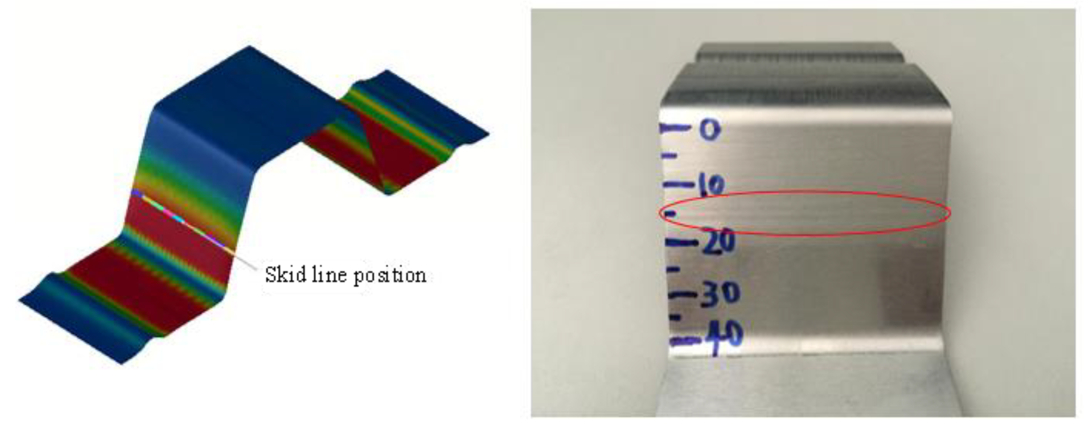
4. Evaluation Method of Skid Line
5. Analysis of Results
5.1. Influence of Die Fillet on Skid Line
5.2. Influence of Drawbead Height on Skid Line
5.3. Effect of Rolling Direction on Skid Line
6. Numerical Simulation Research
6.1. Comparative Analysis of the Influence of Die Fillet on Sheet Skid Line
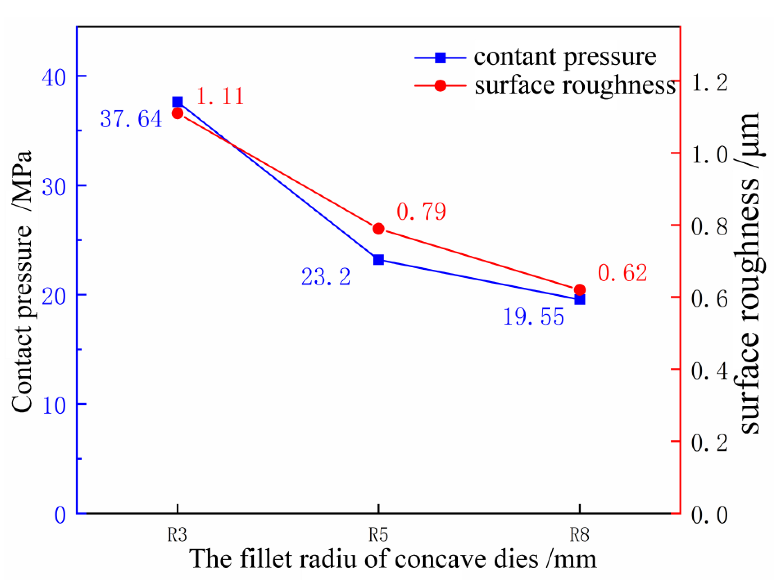
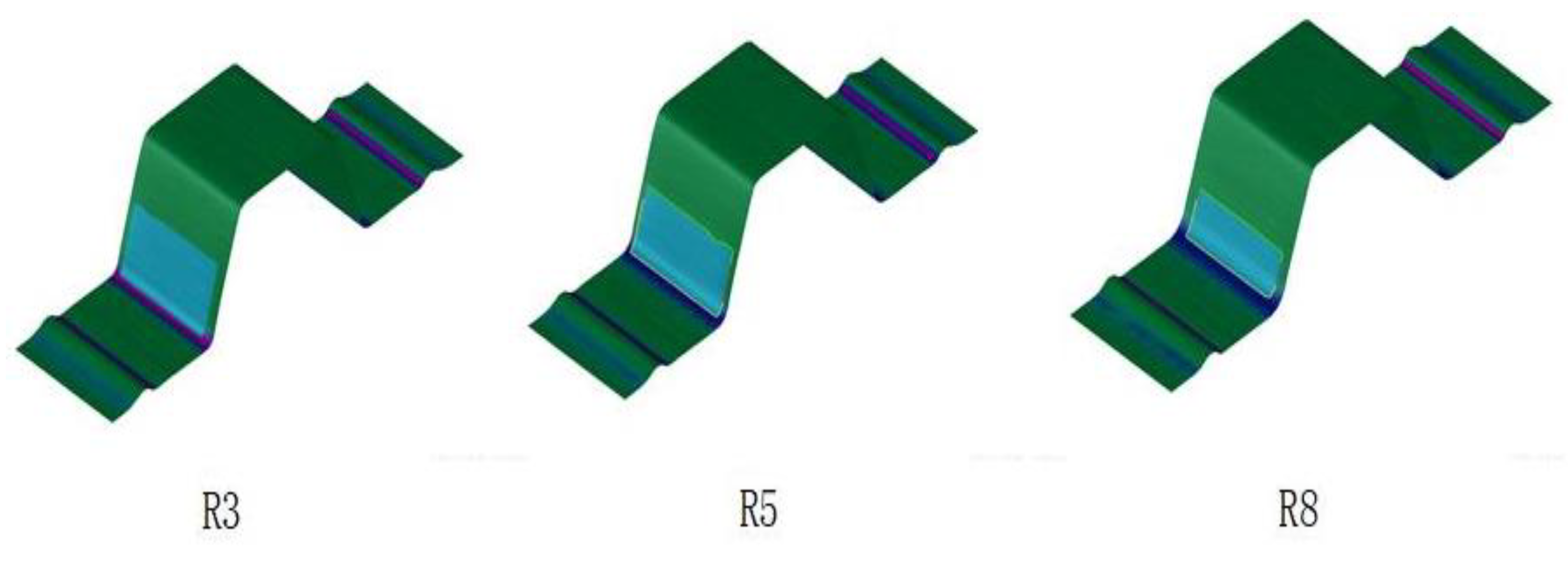
6.1.1. Contact Pressure Analysis
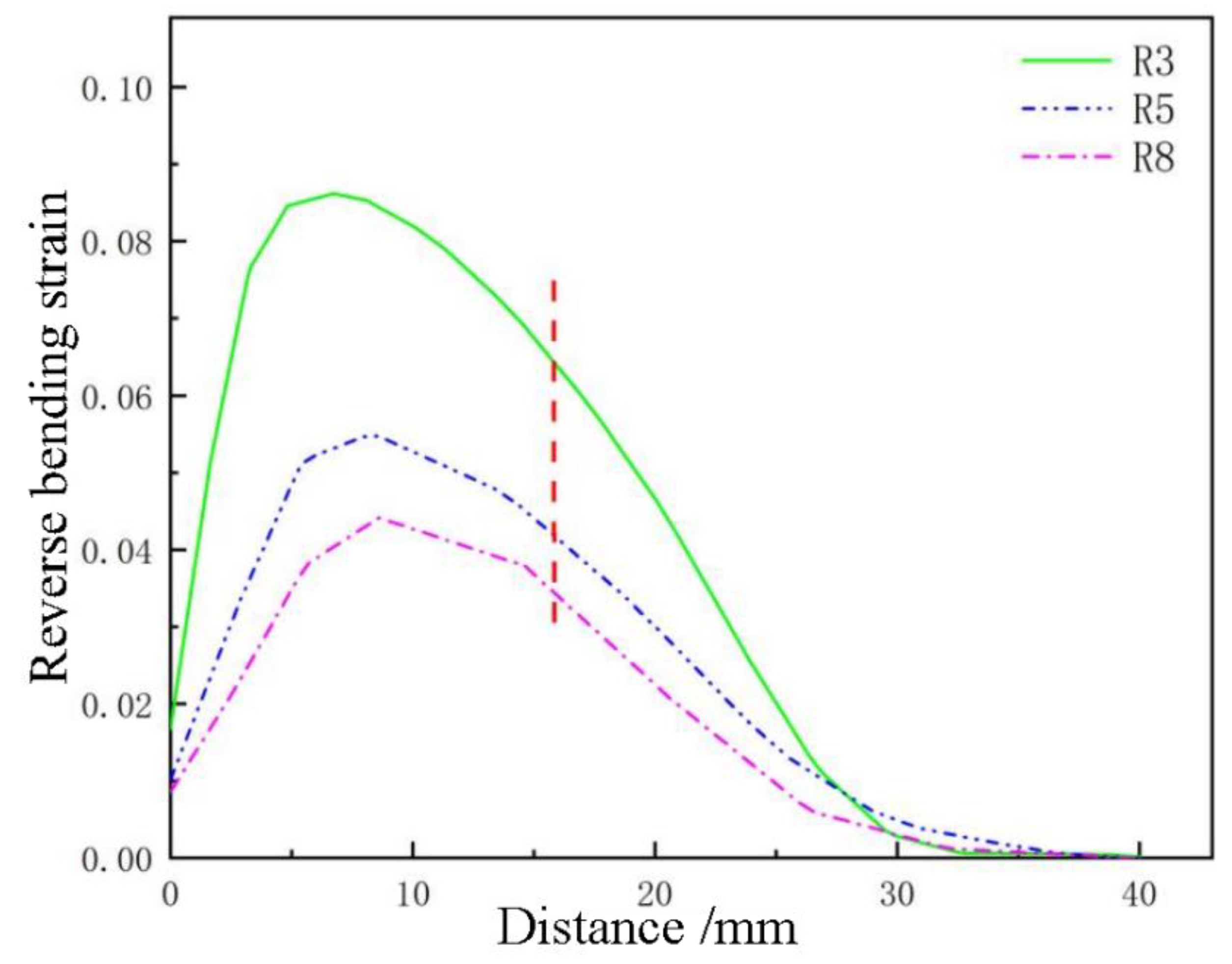
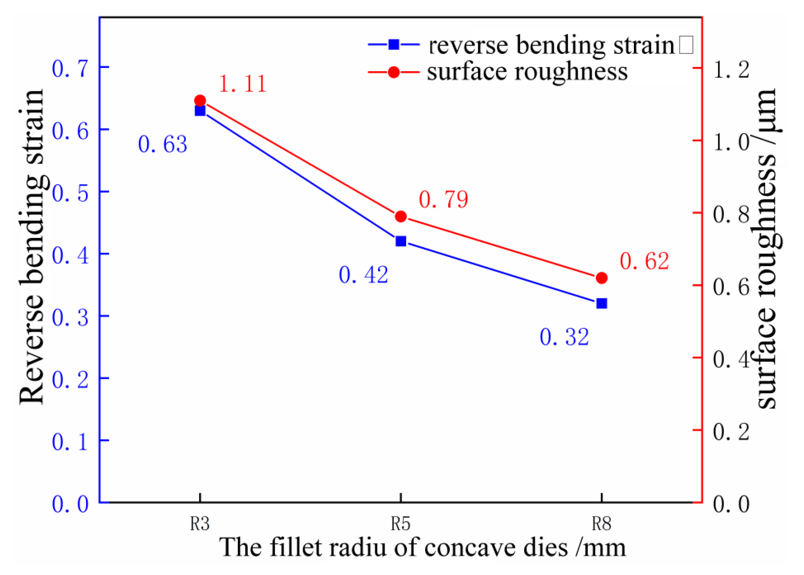
6.1.2. Reverse Bending Strain Analysis
6.2. Comparative Analysis of the Influence of Drawbead on Sheet Skid Line
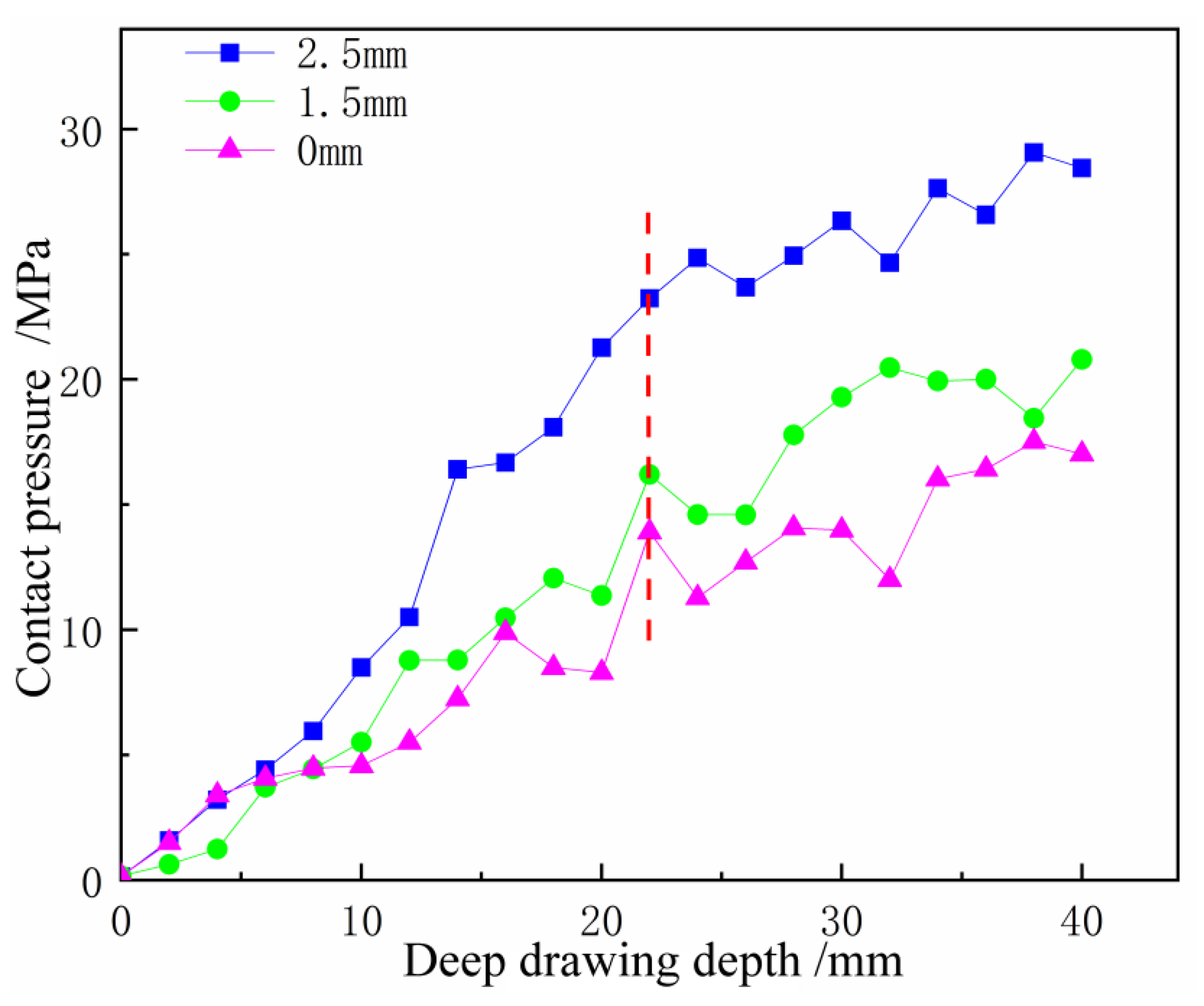
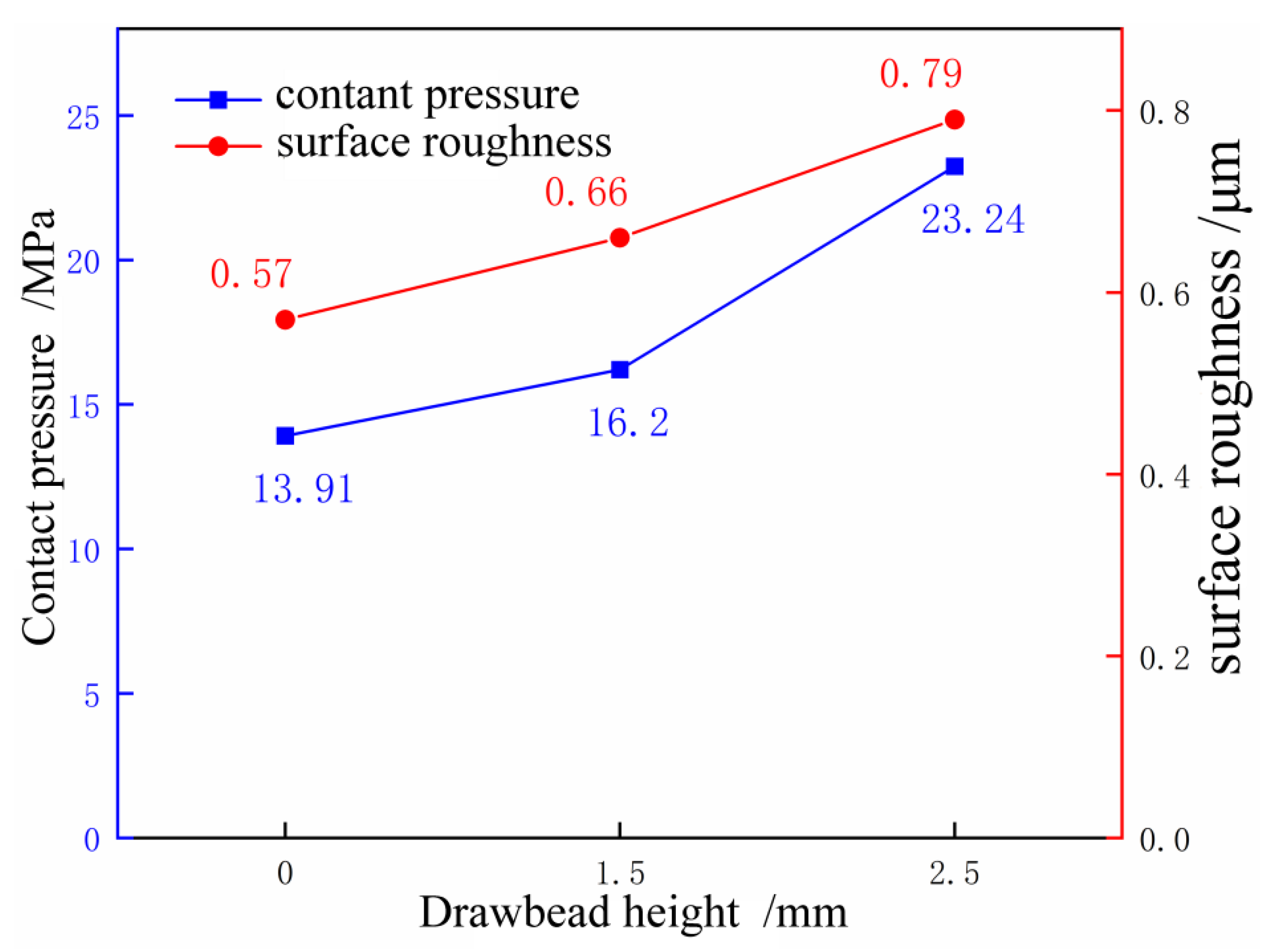
6.2.1. Contact Pressure Analysis
6.2.2. Reverse Bending Strain Analysis
6.3. Comparative Analysis of the Influence of Rolling Direction on Sheet Kid Line
6.3.1. Contact Pressure Analysis
6.3.2. Reverse Bending Strain Analysis
7. Conclusions
- (1)
- The anisotropy coefficients of the aluminum alloy AL6061-T6 material are , , and , respectively. It shows that the material has obvious anisotropic characteristics. Therefore, the Barlat model can describe the mechanical behavior of the AL6061-T6 alloy stamping process.
- (2)
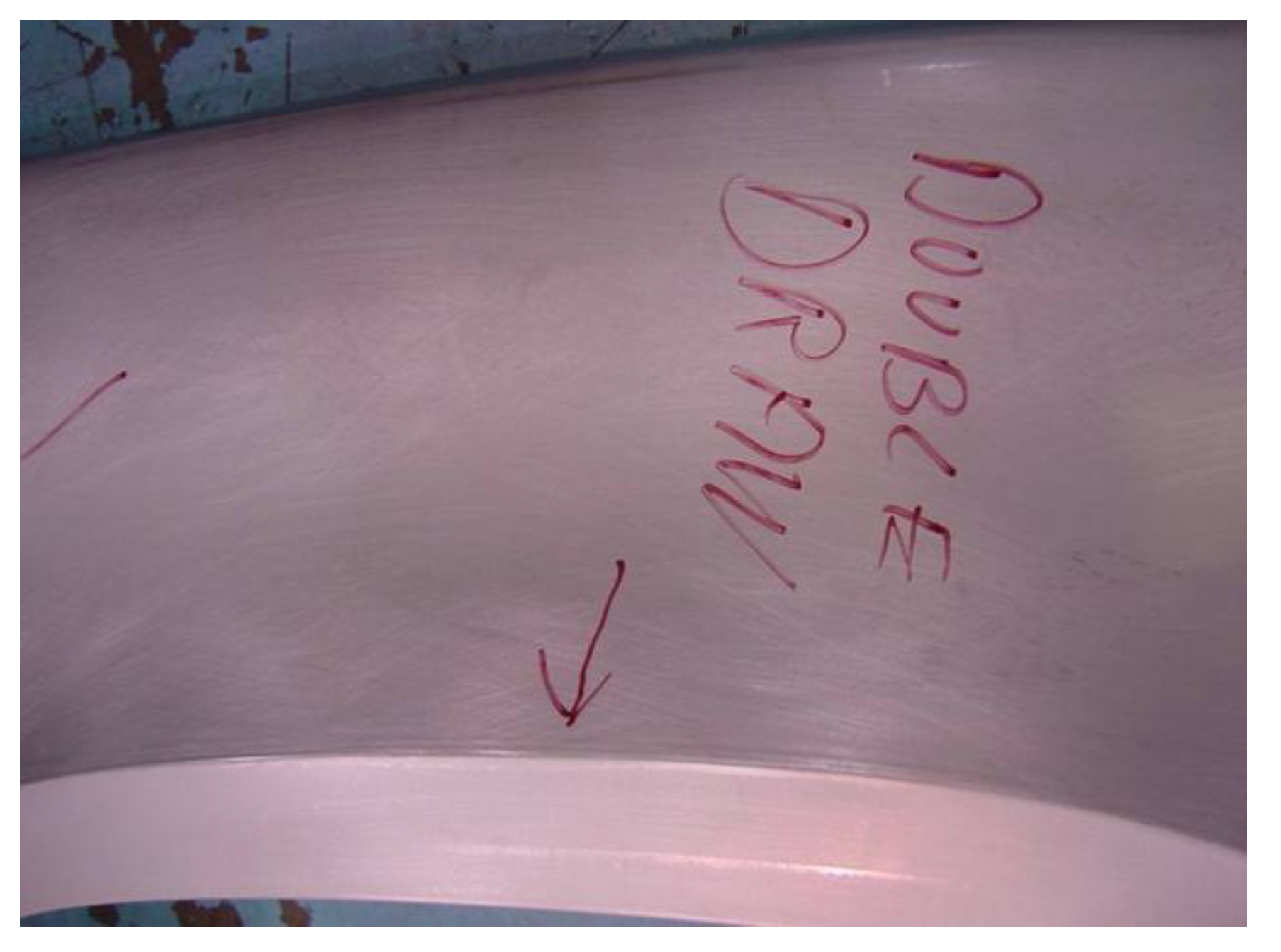
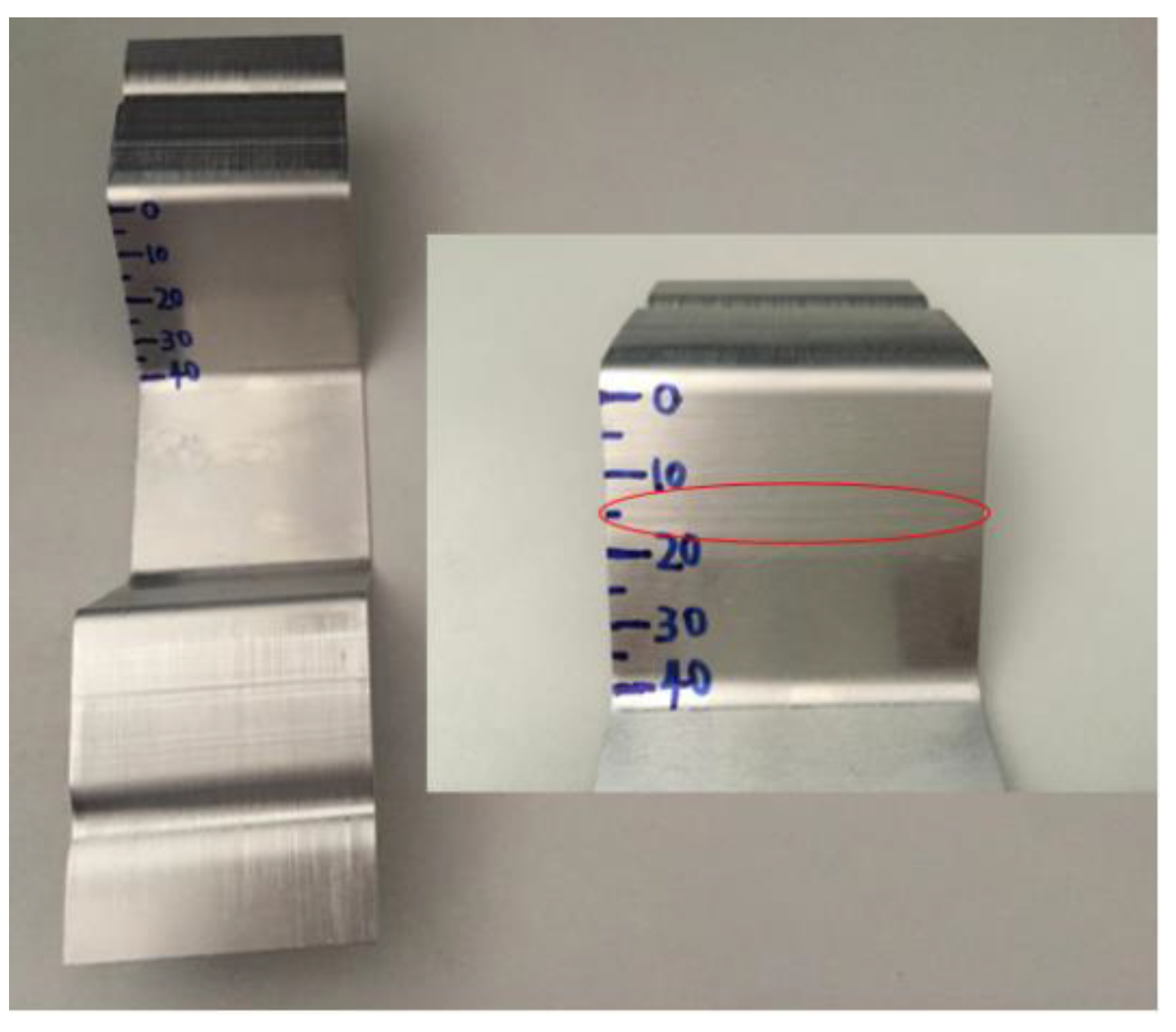
- Skid lines can be characterized by surface roughness. If the roughness is less than 0.6 μm, no skid lines are visible. If the roughness is between 0.6 and 0.9 μm, skid lines are slightly visible. If the roughness is greater than 0.9 μm, skid lines are clearly visible.
- (3)
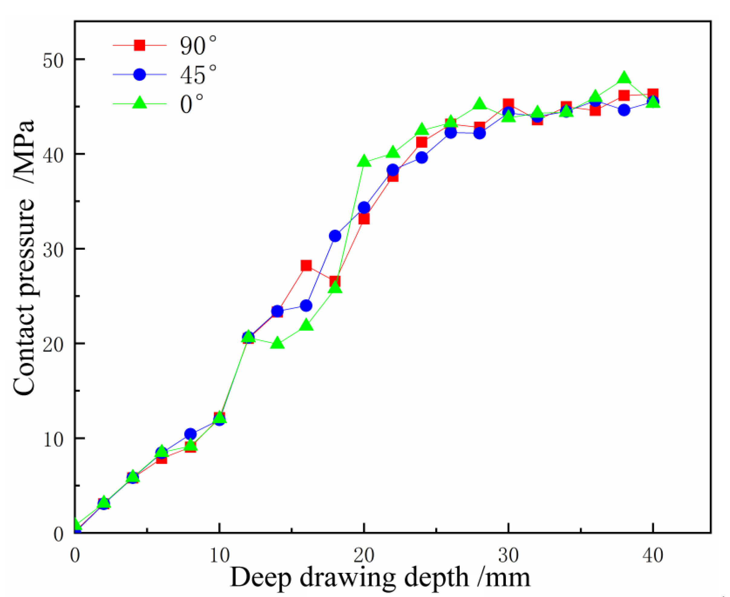
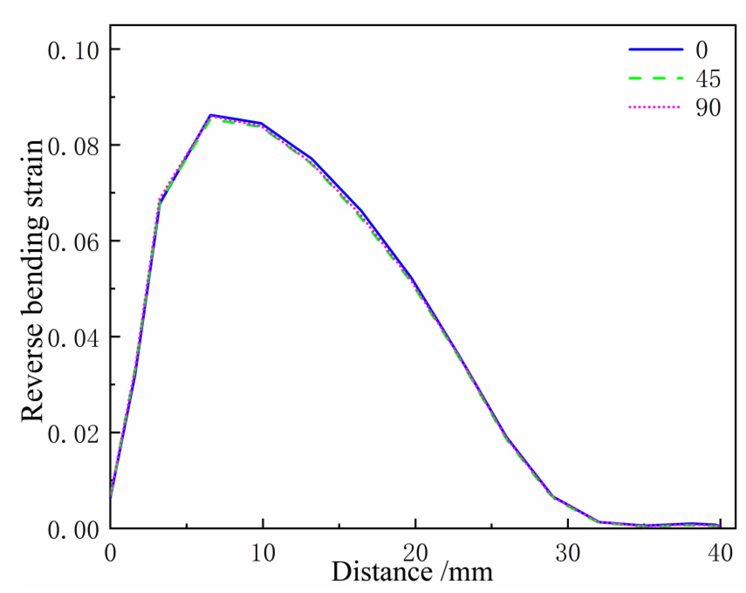
- There is a corresponding relationship between surface roughness, contact pressure, and reverse bending strain: when the roughness is 0.6 μm, the corresponding contact pressure is 16.3 MPa and the reverse bending strain is 3.81%; and when the roughness is 0.9 μm, the corresponding contact pressure is 28.9 MPa and the reverse bending strain is 5.19%. This constitutes the stamping skid line criteria for numerical simulation.
- (4)
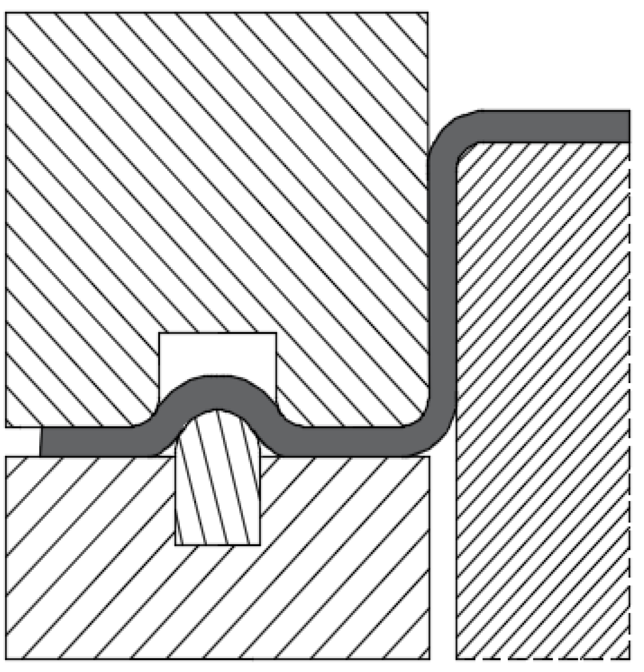
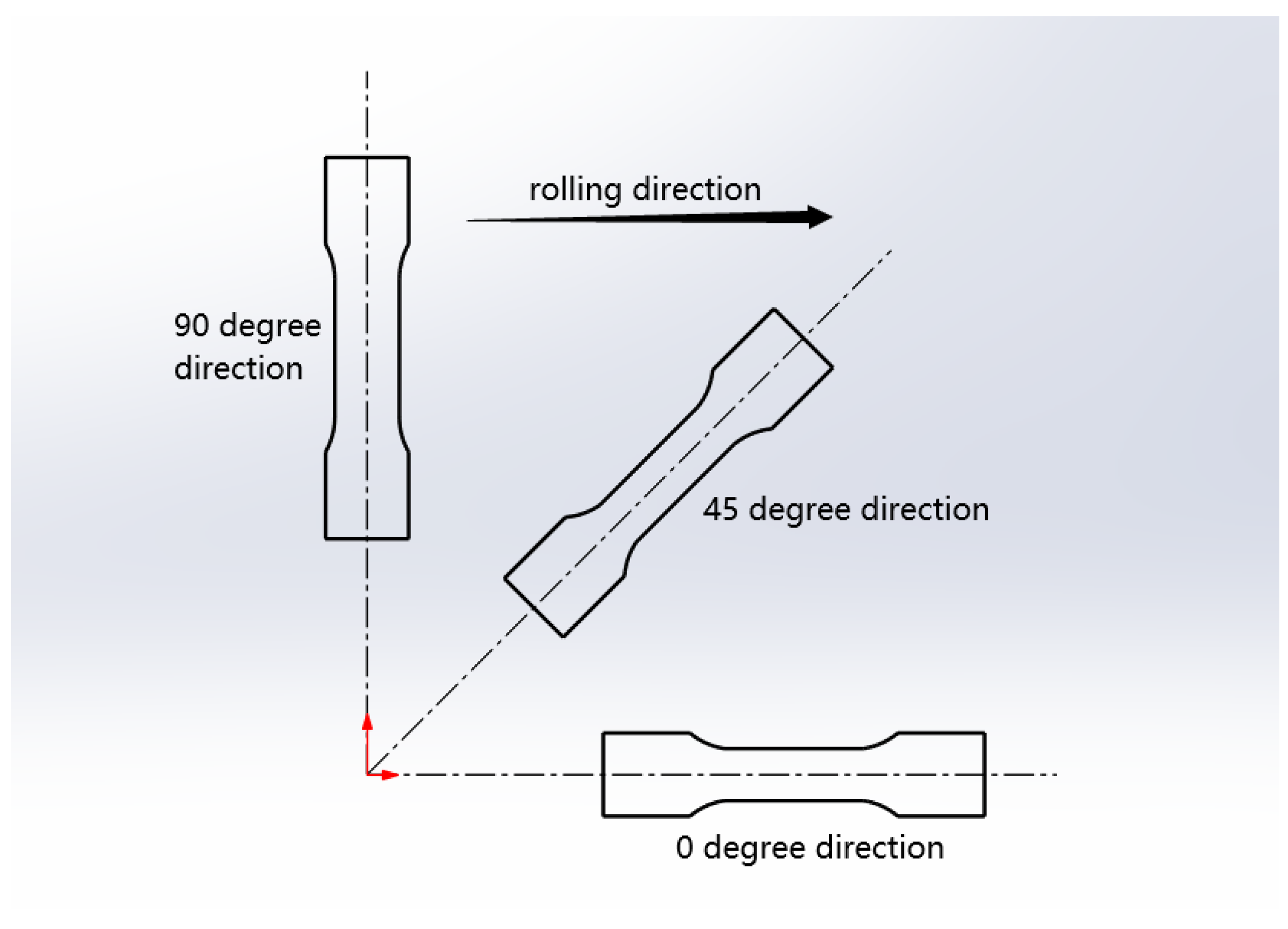
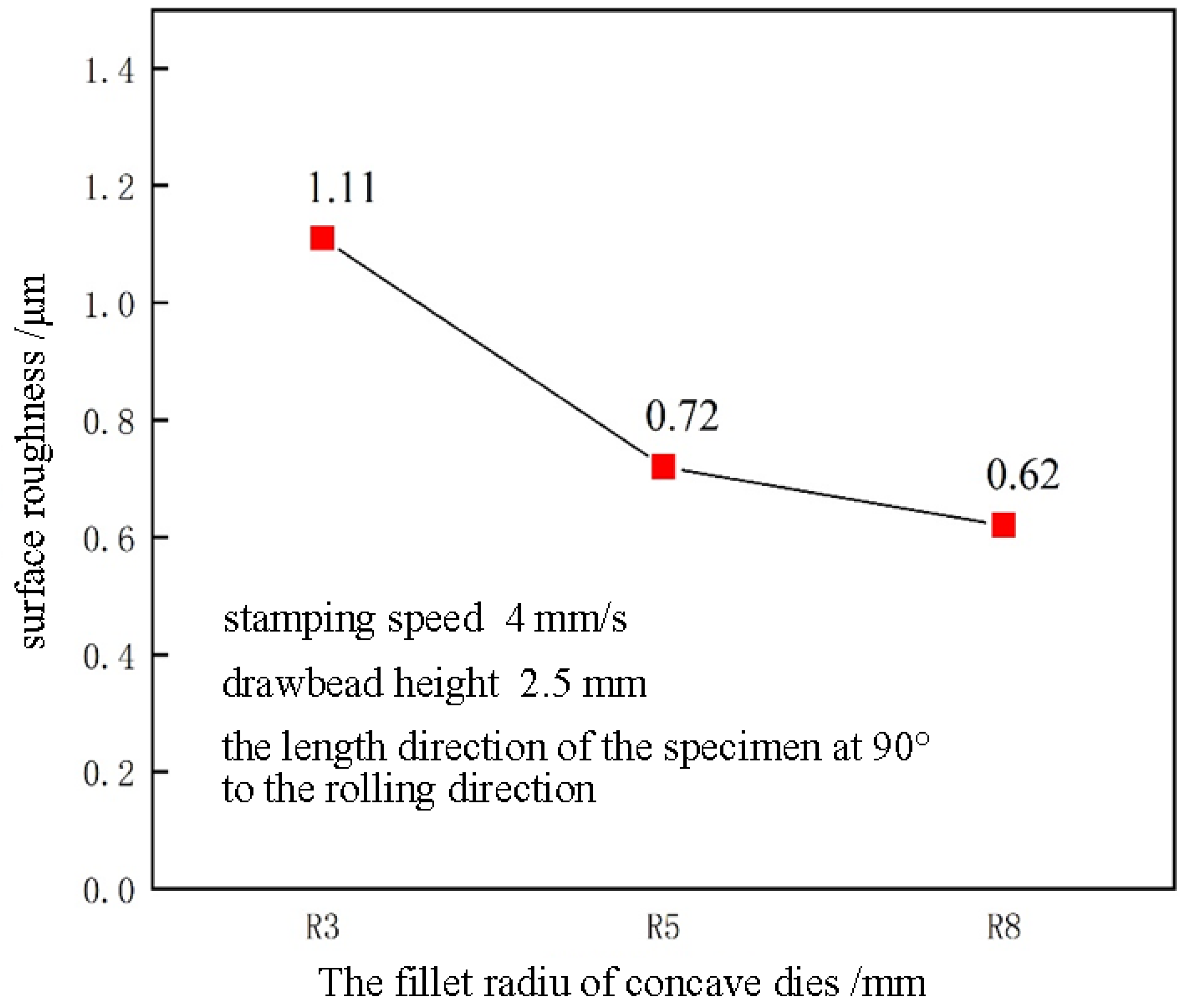
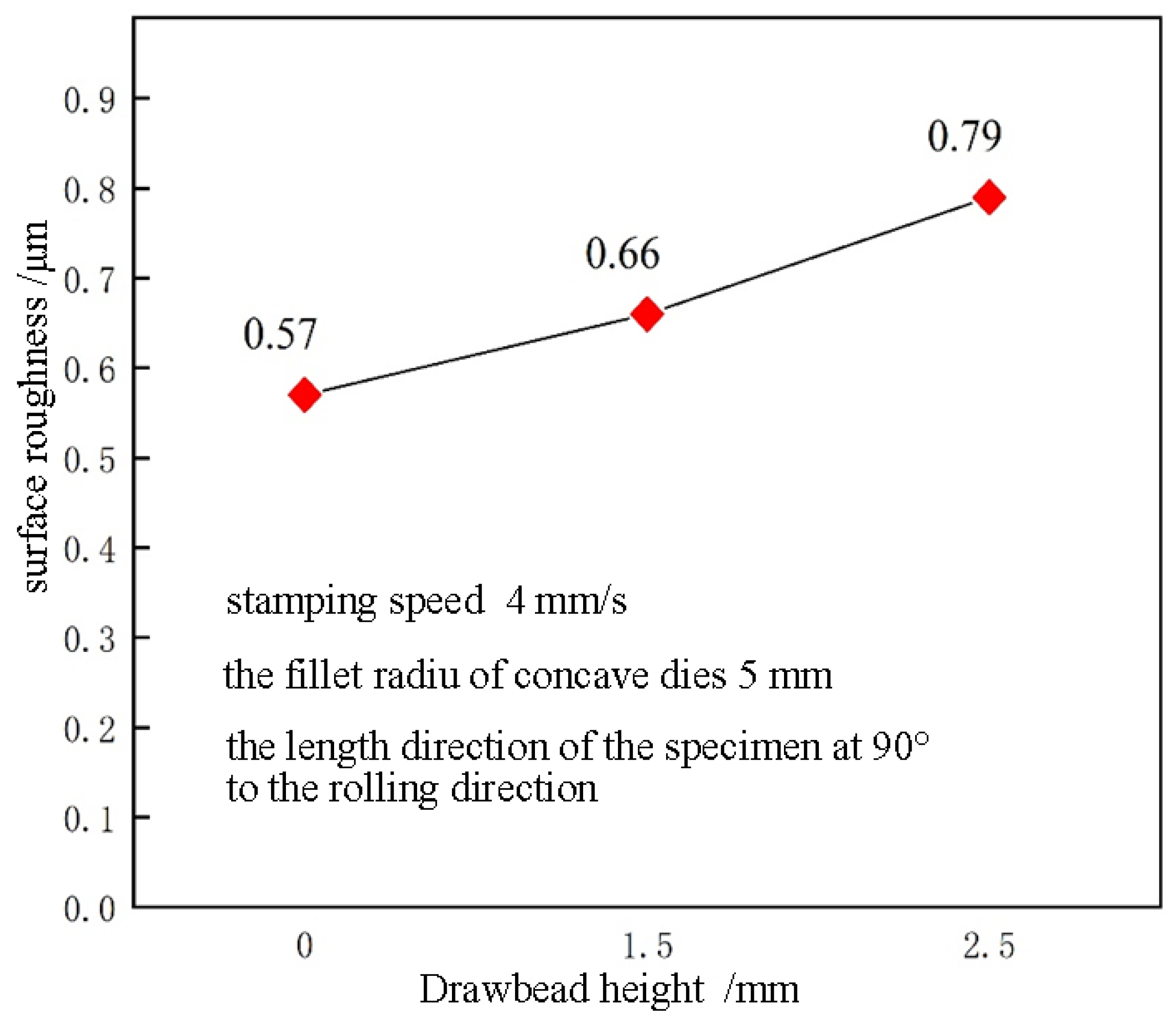
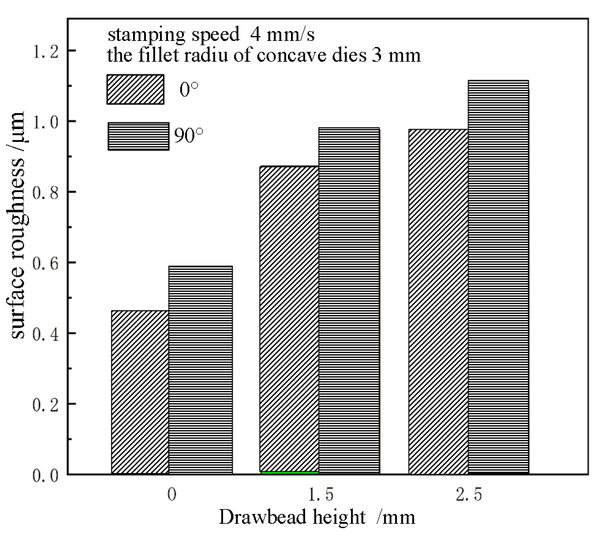
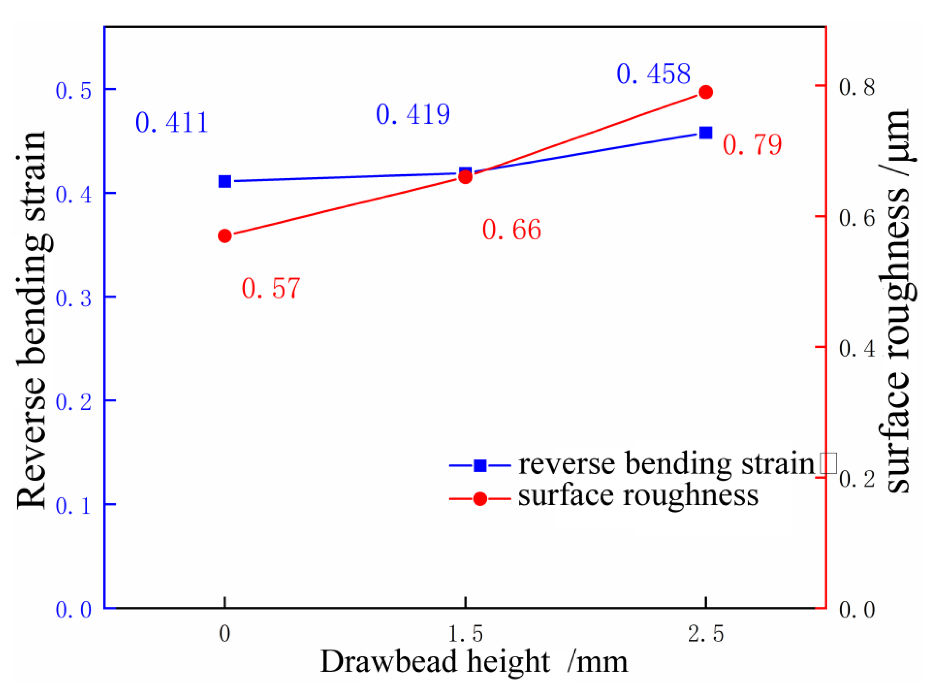
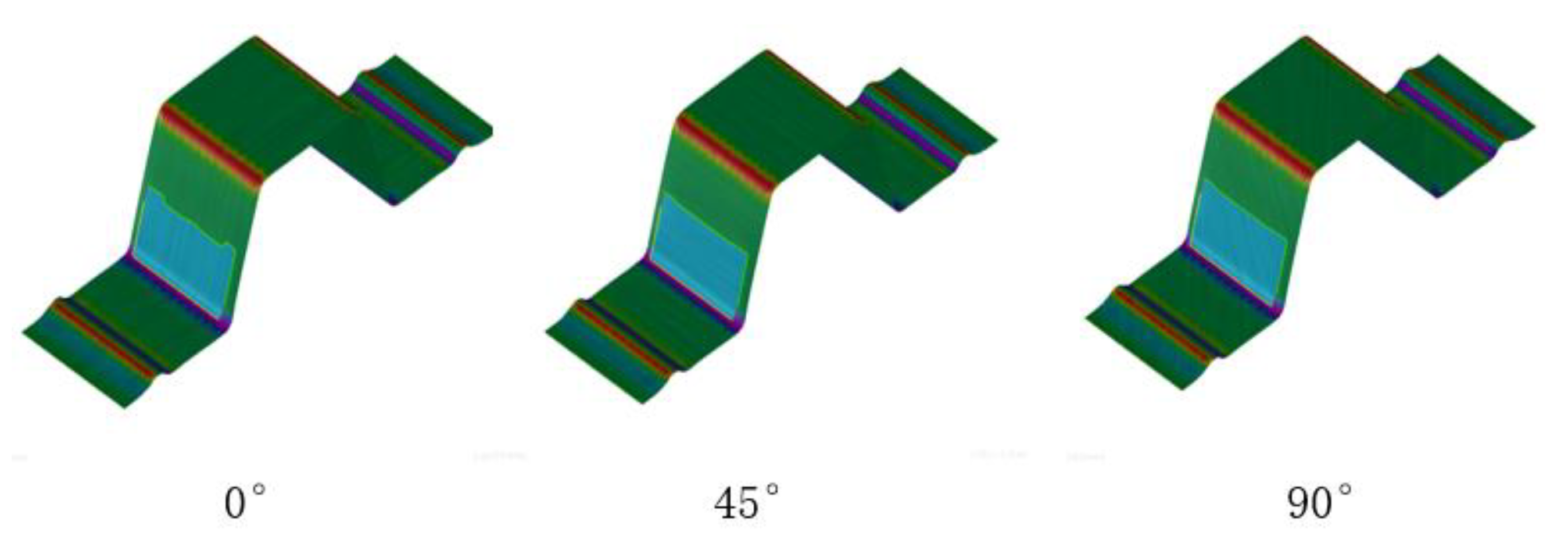
- The severity of the skid line is sensitive to the die fillet. As the die fillet increases, the severity level of the skid line decreases. As the drawbead height increases, the skid line severity level increases. Under the same conditions, the severity levels of the skid lines in different rolling directions are different, and the skid lines in the 90° direction are more serious than those in the 0° direction.
Author Contributions
Funding
Data Availability Statement
Conflicts of Interest
References
- Smith, L.M.; Wanintradul, C.; Gopinath, G.T. Design of Skid Line Simulation Machine for Sheet Metal Surface Quality Analysis. USAMP and A/SP, Shelby Township, Ml, US, US20110271775. 2009. Available online: https://www.freepatentsonline.com/20110271775.pdf (accessed on 8 July 2022).
- Chatchai, W.; Gopinath, T.G.; Smith, L.M. An Experimental Analysis Device for Obtaining Skid Line Limit Diagrams. AIP Conf. Proc. 2011, 1383, 557. [Google Scholar]
- Wanintradul, C.; Gurumurthy, G.T.; Smith, L.M.; Du, C.; Geng, L.; Zhou, D.J.; Hsiung, C.K.; Chen, J.; Feng, C. An experimental analysis device for obtaining skid line limit diagrams. In Proceedings of the 8th International Conference and Workshop on Numerical Simulation of 3D Sheet Metal Forming Processes, Seoul, Korea, 21–26 August 2011; pp. 557–564. [Google Scholar]
- Ren, X.F.; Zhang, Z.B.; Li, G. Prediction of slip line on automobile panel based on finite element simulation. J. Plast. Eng. 2011, 18, 11–15. [Google Scholar]
- Xu, X. Study on the slip line of automobile panel. Die Mould. Technol. 2005, 1, 41–44. [Google Scholar]
- Sima, Z.; Liao, X. Skid Line Optimization and Simulation of Hood Outer Panel Based on AutoForm. J. Chongqing Univ. Technol. 2017, 39–42. [Google Scholar]
- Yang, J.; Liu, Y.; Deng, G. The Methods of Skid-Line Control for the Main Ridge of an Autombile Hood Outer. Mech. Electr. Eng. Technol. 2017, 46, 35–38. [Google Scholar]
- Li, X.; Cheng, Y.; Liu, G.; Jiang, G. Sheet metal stamping analysis of automobile side-panel. Forg. Stamp. Technol. 2011, 36, 27–32. [Google Scholar]
- Wang, L.; Xu, Q.; Zhou, D. Discuss on solution of impact line and slip line for lateral outer panel. Die Mould. Ind. 2017, 43, 24–27. [Google Scholar]
- Cyron, P.; Liewald, M. Prediction and assessment of skid line formation during deep drawing of sheet metal components by using FEM simulation I. In Proceedings of the 24th International Conference on Material Forming, Virtual, 14–16 April 2021. [Google Scholar]
- Cyron, P.; Liewald, M. Prediction and assessment of skid line formation during deep drawing of sheet metal components by using FEM simulation II. In Proceedings of the 40th International Deep Drawing Rseearch Group Conference, Stuttgart, Germany, 21 June–2 July 2021; Volume 1157, p. 012096. [Google Scholar]
- Jiang, M.; Devincre, B.; Monnet, G. Effects of the grain size and shape on the flow stress: A dislocation dynamics study. Int. J. Plast. 2019, 113, 111–124. [Google Scholar] [CrossRef]
- Li, Y.; Hu, S.; Barker, E.; Overman, N.; Whalen, S.; Mathaudhu, S. Effect of grain structure and strain rate on dynamic recrystallization and deformation behavior: A phase field-crystal plasticity model. Comput. Mater. Sci. 2020, 180, 109707. [Google Scholar] [CrossRef]
- Feng, X.; Sun, Y.; Zhou, S.; He, J. Influence of strain rate on microstructures and mechanical properties of 2524Al alloy fabricated by a novel large strain rolling. Mater. Res. Express 2020, 7, 026519. [Google Scholar] [CrossRef]
- Li, X.; Zhang, J.; Li, S. Solution on the sliding line problem of rear door outer panel fender trim. Die Mould. Ind. 2018, 44, 17–20. [Google Scholar]
- Yu, H.; Jiang, S. Detection and solutions for slip line on rear door outer-wheel brow. Die Mould. Ind. 2018, 44, 44–47. [Google Scholar]
- Zhao, Y.; Yang, D.; Wang, Z. Analysis on surface slip line of fender. Die Mould. Ind. 2017, 43, 15–19. [Google Scholar]
- Zhang, P.; Wang, C.; Wang, S. Influence of anistotropy on contact stress of drawing die interface in sheet metal drawing process. Forg. Stamp. Technol. 2015, 40, 14–19. [Google Scholar]
- Keum, Y.T. Expert drawbead models for finite element analysis of sheet metal forming processes. Int. J. Solids Struct. 2001, 38, 5335–5353. [Google Scholar] [CrossRef]






| Thickness/mm | Yield Strength /MPa | Tensile Strength/MPa | Elongation/% | Strain Index n | Plastic Strain Ratio |
|---|---|---|---|---|---|
| 1.0 | 119 | 224 | 22 | 0.28 | 0.81 |
| AL6061-T6 | 0.762 | 0.493 | 0.795 | 0.686 | 0.286 |
| Surface Roughness/μm | Visual Degree | Severity Level |
|---|---|---|
| 0.6 or less | Invisible | 1 |
| 0.6~0.9 | Slightly visible | 2 |
| 0.9 or above | Clear visible | 3 |
Publisher’s Note: MDPI stays neutral with regard to jurisdictional claims in published maps and institutional affiliations. |
© 2022 by the authors. Licensee MDPI, Basel, Switzerland. This article is an open access article distributed under the terms and conditions of the Creative Commons Attribution (CC BY) license (https://creativecommons.org/licenses/by/4.0/).
Share and Cite
Zhao, D.; Zhang, C.; Zhao, K.; Xie, Y. Experimental Study and Simulation-Based Criterion for Stamping Skid Line. Machines 2022, 10, 890. https://doi.org/10.3390/machines10100890
Zhao D, Zhang C, Zhao K, Xie Y. Experimental Study and Simulation-Based Criterion for Stamping Skid Line. Machines. 2022; 10(10):890. https://doi.org/10.3390/machines10100890
Chicago/Turabian StyleZhao, Dewang, Chao Zhang, Kunmin Zhao, and Yanhao Xie. 2022. "Experimental Study and Simulation-Based Criterion for Stamping Skid Line" Machines 10, no. 10: 890. https://doi.org/10.3390/machines10100890
APA StyleZhao, D., Zhang, C., Zhao, K., & Xie, Y. (2022). Experimental Study and Simulation-Based Criterion for Stamping Skid Line. Machines, 10(10), 890. https://doi.org/10.3390/machines10100890


