Article

Dual Fuzzy Energy Control Study of Automotive Fuel Cell Hybrid Power System with Three Energy Sources

1
School of Automation, Guangxi University of Science and Technology, Liuzhou 545000, China
2
Guangxi Key Laboratory of Auto Parts and Vehicle Technology, Guangxi University of Science and Technology, Liuzhou 545000, China
3
School of Mechanical and Automotive Engineering, South China University of Technology, Guangzhou 510335, China
4
School of Electronic Engineering, Guangxi University of Science and Technology, Liuzhou 545000, China
*
Author to whom correspondence should be addressed.
Machines 2022, 10(10), 880; https://doi.org/10.3390/machines10100880
Submission received: 26 August 2022 / Revised: 18 September 2022 / Accepted: 28 September 2022 / Published: 1 October 2022
(This article belongs to the Section Electromechanical Energy Conversion Systems)

Abstract

:
A dual fuzzy control strategy is proposed for the complex energy management problem in a multi-energy-source hybrid power system vehicle with fuel cell + Li-ion battery + super capacitor. According to the efficiency characteristic of each energy source in a fuel cell hybrid power system (referred to as FCHPS), a control scheme with a dual fuzzy control strategy is devised, in which the main fuzzy controller controls the fuel cell to ensure its power output. It is controlled by a sub-fuzzy controller that regulates the power output and braking energy recovery of the Li-ion battery and super capacitor. Simulation verification and comparative analysis were carried out under a world light vehicle test cycle (referred to as WLTC) conditions using MATLAB+ADVISOR. With a dual fuzzy control strategy, fuel cell hybrid vehicles meet dynamics requirements and the fuel economy of these vehicles is generally 6.7% and 6.4% better than power following control and single fuzzy control, respectively. Li-ion batteries are also capable of handling reduced average currents.

1. Introduction

A new generation of automotive power sources is being researched in the direction of fuel cells [1,2,3]. The development of a rational energy management strategy is one of the main focuses in fuel cell hybrid systems [4]. The hybrid system consisting of fuel cell + power cell + super capacitor (referred to as FC+BA+SC) is one of the hot spots of current research. The study of [5] illustrates that triple-energy-source fuel cell vehicles are more efficient and have longer battery life than dual-energy-source fuel cell vehicles when considering vehicle performance, fuel economy, and powertrain cost. The disadvantage is that the system structure is complex and the control is difficult. This paper is based on this fuel cell hybrid power system for energy management control research.
There are two main categories of fuel cell vehicle energy control strategies, rule based and optimization based [6,7,8]. The biggest advantage of rule-based energy control strategies is that they can achieve real-time control, including fuzzy control strategies, logic threshold control strategies, and sliding film control [9]. Fuzzy control provides good control for energy management systems with complex structures and multiple variables [10]. This type of control can be used in fuel cell hybrid systems to control the DC bus voltage and to put into use a battery, super capacitor, or battery + super capacitor, which can reduce the hydrogen consumption of the fuel cells and can also be used to recover braking energy [11]. The study of [12] used logic thresholds to constrain the fuel cell power and power cell SOC based on fuzzy control to control the fuel cell turn-on when the vehicle demand power and power cell SOC reach certain limits to meet the vehicle dynamics requirements, but the scheme can also be implemented using only fuzzy control. In the study of [13], a fuel cell electric vehicle energy management strategy based on wavelet and fuzzy control strategy is proposed to satisfy the dynamics of the whole vehicle while ensuring the economy. The power cell current is better controlled, which is good for its lifetime, but the fuel cell system is switched on and off too many times, which is not good for the fuel cell lifetime. The study of [14] combined two types of rule-based energy control, power following and fuzzy control, to control the output of the fuel cell system by controlling the SOC value of the battery or super capacitor, with better control in real time, but the power cell basically only plays the function of energy recovery and the power cell is not well used. The study of [15] proposed a fuzzy control strategy for a three-energy-source system and designed a dual fuzzy controller for drive mode and braking mode to meet the power requirements of the whole vehicle, but the fuzzy controller in drive mode does not consider the energy recovery of the power battery. When the power battery SOC is small, it also cannot implement charging of the power battery, so this paper designs a dual fuzzy controller for the output control of fuel cell and power battery and to achieve the energy recovery function during braking. The main optimization-based energy management strategies are model-predictive control, dynamic programming, the principle of minimal values, etc. For example, the study of [16] proposed an adaptive energy management strategy for fuel cell hybrid systems based on the Pontryagin minimal value principle, which resulted in better fuel economy, a 4% reduction in hydrogen consumption, and relatively low average power variability in the fuel cell. The study of [17] et al. used stochastic dynamic programming to optimize the vehicle to minimize the operating cost and effectively increase the fuel cell life by 14%. Optimization-based energy control strategies are more effective in control but have poor real-time performance due to their generally large computational effort [18,19].
The structure of the three-energy-source fuel cell hybrid power system is complex and the working status of each energy source is tedious when providing energy for the whole vehicle. By using each energy source rationally and making good use of their respective characteristics, we can improve the efficiency of the energy sources. Using a dual fuzzy control strategy, this paper implements a layered control strategy for a fuel cell hybrid system, achieving the goals of improving the fuel economy of the entire vehicle, reducing the number of fuel cell starts and stops, and reducing the Li-ion battery current shock. The control scheme of the dual fuzzy control strategy is: the main-fuzzy controller controls the fuel cell to ensure the power output of the fuel cell; the sub-fuzzy controller controls the Li-ion battery and super capacitor to control the power output and braking energy recovery of both. Compared with the commonly used power following control and single fuzzy control, the dual fuzzy control strategy control proposed in this paper offers better fuel economy and extends fuel cell and power cell service life.
The structure of this paper is as follows. Section 1 focuses on establishing the simulation models of the fuel cell, Li-ion battery and super capacitor, and the power demand model of the whole vehicle. Section 2 proposes a dual fuzzy control strategy for output power calculation of the fuel cell, Li-ion battery and super capacitor, as well as braking energy recovery of Li-ion battery and super capacitor. Section 3 provides simulation verification and comparative analysis of different strategies. The conclusions are presented in Section 4.

2. Hybrid Power System Modeling for Fuel Cell Vehicles

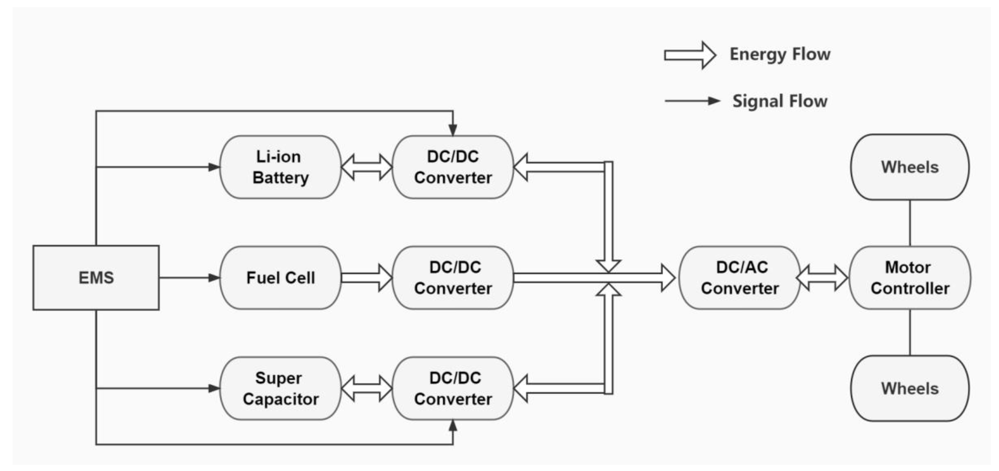
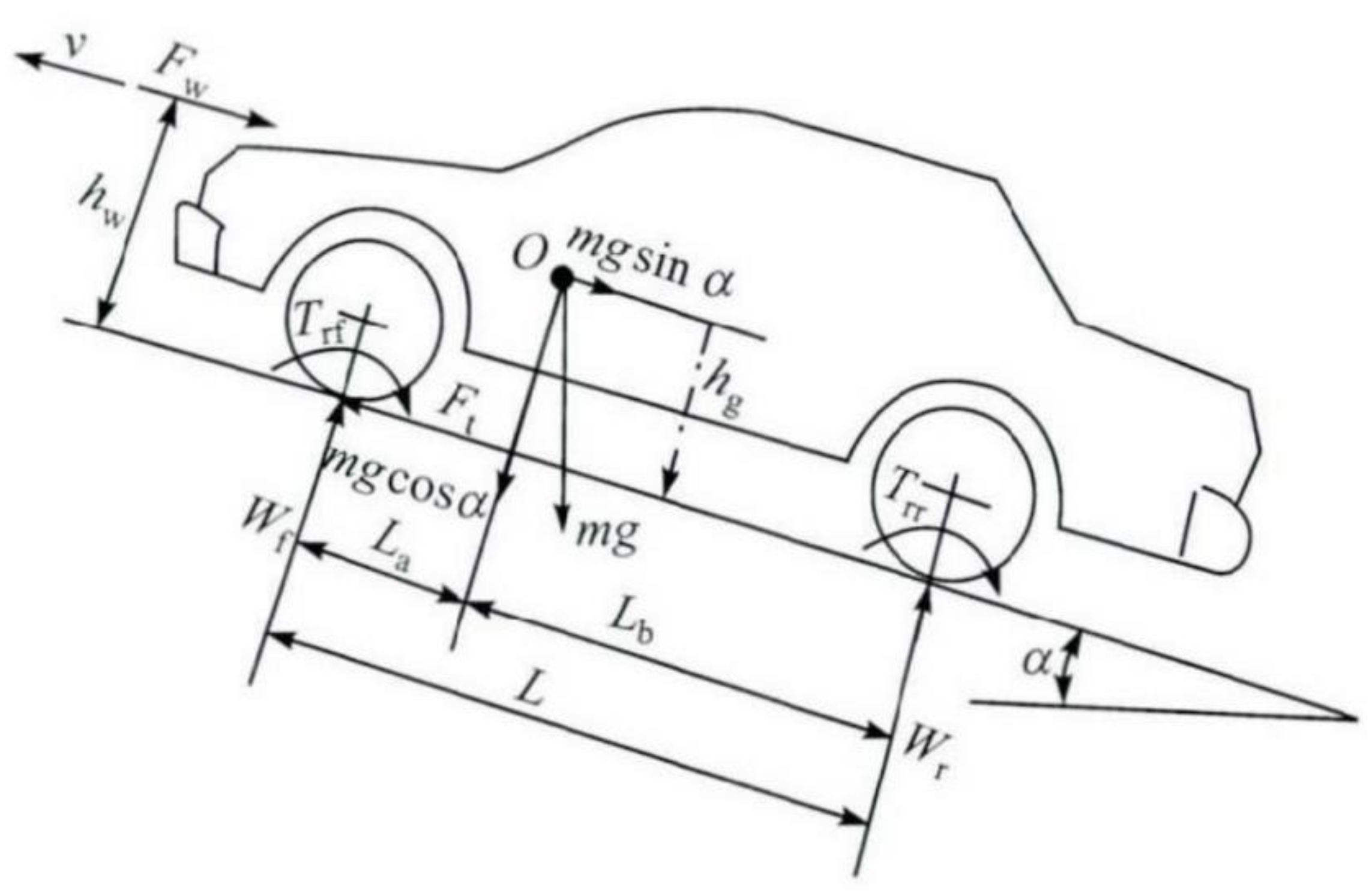
2.1. Whole-Vehicle Power System Model

The structure of the fuel cell hybrid power system consisting of a fuel cell, power cell, and super capacitor is shown in Figure 1, where the fuel cell is used as the main power source, the power cell provides more stable power support, and the super capacitor provides larger instantaneous power support as well as recovery of larger power energy.
In the process of driving, the car needs the driving force to produce power to meet the car’s dynamics requirements, but in the process of driving, it will be subject to driving resistance. Figure 2 represents the force situation of the car driving uphill in the process of driving. According to Newton’s second law, the force equation of the car driving is:
F t = F
where F t is the driving force and F is the sum of driving resistance.
When a car is driven on the road, there is usually air resistance F w , tire rolling resistance F f , climbing resistance F i , and acceleration resistance F j . The driving force of the car can be expressed by Equation (2) [20]:
F t = P f f cos α + 1 2 C D A ρ u r 2 + M g sin α + δ M d u d t
where P is the load; f f is the rolling resistance coefficient; α is the ground slope angle; C D is the air resistance coefficient; ρ is the air density; A is the windward area; u r is the relative speed; δ is the car rotating mass conversion factor; d u d t is the driving acceleration.
In order to model the vehicle dynamics in ADVISOR software, the parameters of each unit in the fuel cell hybrid power system vehicle are selected, as shown in Table 1.

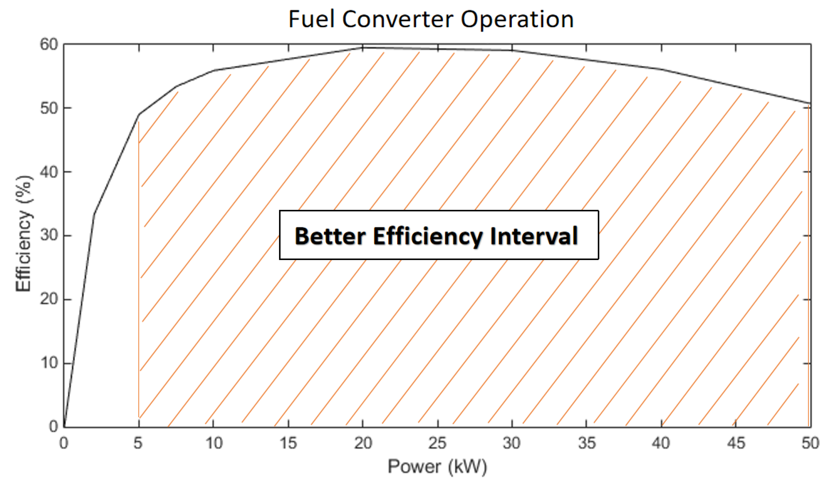
2.2. Fuel Cell Model

The fuel cell model was chosen from the power-efficiency type of the proton exchange membrane fuel cell system in ADVISOR software, which consists mainly of a fuel consumption module and an emission module, and this model is used without considering the specific operating characteristics. The curves of model power and efficiency are shown in Figure 3, from which it can be seen that the hydrogen combustion efficiency is better when the output power of the fuel cell is in a range of 5–50 kW [21].
The power required to be supplied by the fuel cell when the car is powered by the fuel cell alone and the car is running steadily at maximum speed is [22]:
P f c = 1 η d c η t η e ( m g f v max 3600 + C D A v max 3 76140 )
where η d c , η t , and η e denote the efficiency of DC/DC converter, transmission coefficient, and motor controller, respectively, and v max denotes the maximum vehicle speed.

2.3. Power Cell Model

The model chosen for the power cell is the Rint model lithium-ion battery in ADVISOR and the current in the power cell can be expressed as [22]:
I = V O C V O C 2 4 R P 2 R
From the equivalent circuit, the power P = V I and Kirchhoff’s voltage law V = V O C R I can be obtained:
V O C I = P + I 2 R
The expression for the state of charge in the power cell can be expressed as:
S O C ( t ) = S O C 0 i d t Q ( i )
where S O C 0 is the charge state value of the power cell at the initial moment, S O C ( t ) is the charge state value of the power cell at moment t, and Q ( i ) is the power cell capacity corresponding to the rate of change in current.

2.4. Super Capacitor Model

The super capacitor satisfies Equation (7):
{ U t = U C i R S d U C d t = i i L C i L = U C R L d U C d t = 1 C ( U C R L + i ) U C = [ U C O 0 t i C e i / C R L d t ] e ( t / C R L ) S O C S C = ( U C U C M ) 2
where U t is the super capacitor terminal voltage, U c is the terminal voltage of the super capacitor unit, R s is the series resistance, i L is the leakage current, R L is the leakage resistance, i is the discharge current, and U C M is the full charge voltage.

3. Dual Fuzzy Energy Control Strategy

3.1. Overall Program

For the FCHPS, the EMS has a complex logic relationship to allocate energy to the fuel cell, Li-ion battery, and super capacitor according to the vehicle driving conditions. In order to control the energy distribution in this system using a single fuzzy controller, two outputs must be controlled simultaneously, which, for this system, would require more complex fuzzy control rules. If two structurally simple fuzzy controls are used instead of a complex single fuzzy control, the logic of the control becomes simple and clear, which facilitates the determination of fuzzy rules. The framework of the dual fuzzy control idea is shown in Figure 4, which uses a joint control scheme of a main fuzzy controller and a sub-fuzzy controller, with the main fuzzy controller controlling the fuel cell energy output and the sub-fuzzy controller controlling the Li-ion battery and super capacitor energy outputs and braking energy recovery. Considering that the power demand of the whole vehicle is mainly satisfied by three energy sources, as long as the output power of two energy sources is determined, the output power of the third energy source can be naturally determined. As a result, this paper develops two simple fuzzy controllers with single outputs to control the power output of fuel cells and Li-ion batteries. These objectives include meeting the vehicle’s power requirements, improving fuel economy, reducing the number of fuel cell starts and stops, and reducing the Li-ion battery’s current shock.

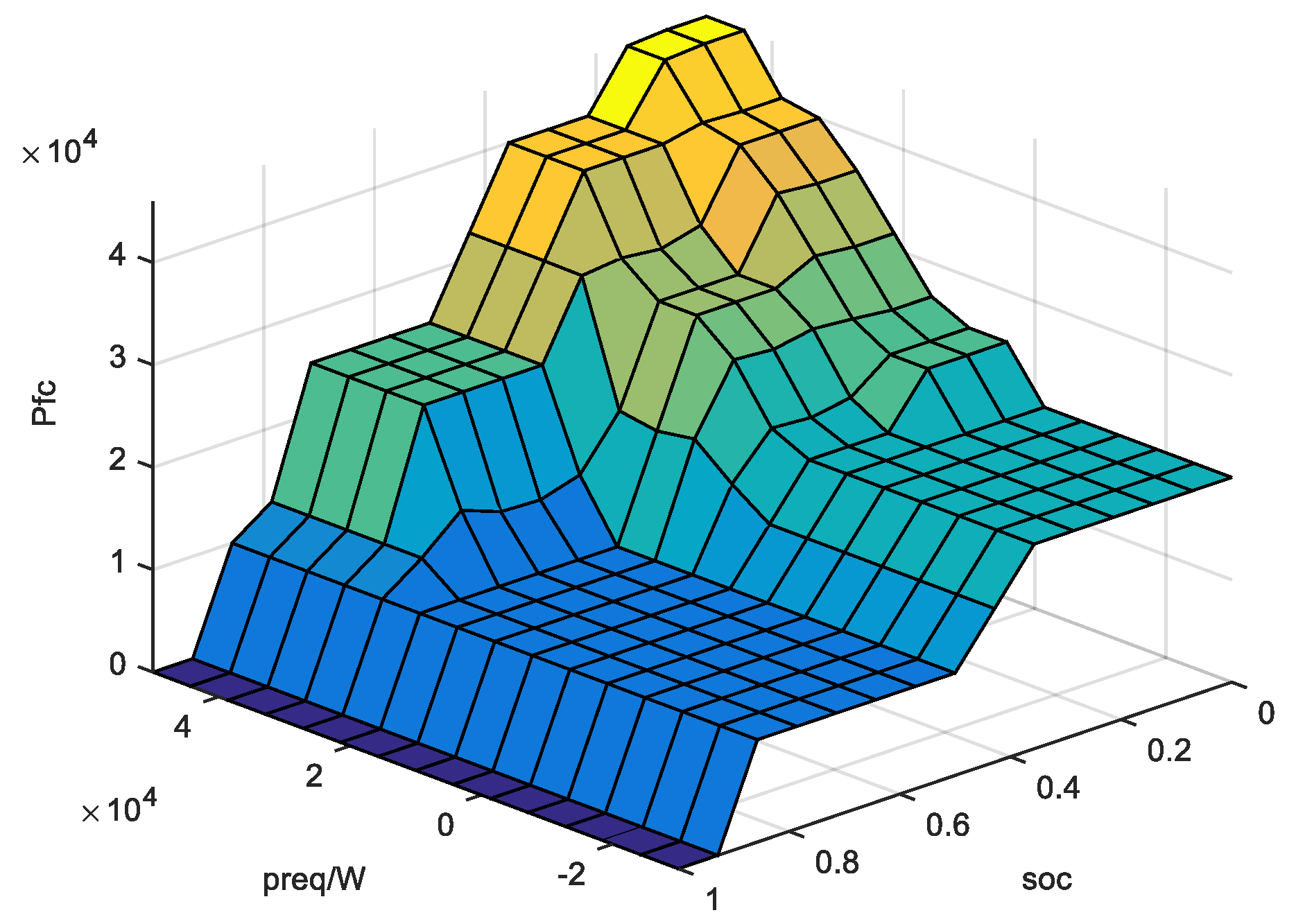
3.2. Main Fuzzy Controller

The main fuzzy controller is a two-input single-output fuzzy controller with the input variables being the demand power of the whole vehicle and the SOC of the power Li-ion battery and the output variable being the fuel cell output power. The affiliation function is the basis for the application of fuzzy control and the correct construction of an appropriate affiliation function is one of the keys to using fuzzy control well. The shape of the affiliation function has different effects on the control characteristics, where the triangular affiliation function has a sharp shape, high resolution of the input signal, and more sensitive control characteristics for energy source SOC. Therefore, the main fuzzy controller input variable power Li-ion battery SOC selected this shape of the affiliation function; trapezoidal affiliation function has a gentler shape and smoother control characteristics for power class variables. The main fuzzy controller input demand power, Li-ion battery SOC, selected this shape of the affiliation function, as shown in Figure 5.
The whole vehicle demand power is designed with nine states according to the power from small to large, which are {zero, very small, extra small, smaller, small, medium, large, larger, and very large} and the fuzzy input variables are {Z, SSS, SS, MS, HS, M, SH, MH, and HH}, where Z indicates that the demand power is zero and indicates the braking condition of the vehicle. Considering the large capacity of the power Li-ion battery, the Li-ion battery SOC is set to be designed for five states, which are {very low, low, medium, high, and very high} and the fuzzy input variables are {XL, L, M, H, and XH}; the fuzzy control rules for the main fuzzy controller designed are shown in Table 2. The meaning of the fuzzy control rule is:
  • FCHPS braking energy recovery is controlled at this time by the sub-fuzzy controller introduced below when the demand power of the FCHPS is zero (Z) and the output power of the fuel cell is zero (Z). The total power expression is:
    { P m η m = P r e q P f c = 0 P B η D C / D C 1 + P C η D C / D C 2 = P m
    where P f c , P B , P C , P m , and P r e q are fuel cell, lithium battery, super capacitor, motor output power, and overall vehicle demand power, respectively, and η m , η D C / D C 1 , and η D C / D C 2 are DC/DC conversion efficiency of motor efficiency, lithium battery, and super capacitor, respectively.
  • When the FCHPS demand power is small (SSS, SS, MS) and the Li-ion battery SOC is very low or low (XL, L), the energy is provided by the fuel cell and the total power expression is:
    P f c = P + m P B η D C / D C 1 + P C η D C / D C 2
  • Fuel cell is turned off when the lithium battery SOC reaches medium and above (M, H, XH) and the following sub-fuzzy controller controls the Li-ion battery and super capacitor energy outputs. The total power expression is:
    { P f c = 0 P B η D C / D C 1 + P C η D C / D C 2 = P m
  • When the FCHPS demand power is medium (HS, M, SH), when the fuel cell provides the main power and keeps the hydrogen combustion in a good range (SS, MS, HS, M), the remaining energy is obtained by the sub-fuzzy controller control and the total power expression is:
    P f c = P + m P B η D C / D C 1 + P C η D C / D C 2
  • When FCHPS demand power is high (MH, HH), then fuel cell, Li-ion battery, and super capacitor need to work together. The fuel cell output is kept at medium and above (M, SH, MH, HH, H) and charging and discharging of Li-ion battery and super capacitor are controlled by sub-fuzzy controller and the total power expression is:
    P f c + P B η D C / D C 1 + P C η D C / D C 2 = P m
The Mamdani [23] inference method is used for fuzzy inference and the area center of gravity method is used to transform the vector into unit values for defuzzification [24]. Figure 6 shows a fuel cell output power surface diagram.
v 0 = v μ ( v ) d v μ ( v ) d v
where v 0 is the judgment result of fuzzy output, v is the element of the set in the field, and μ ( v ) is the affiliation degree.

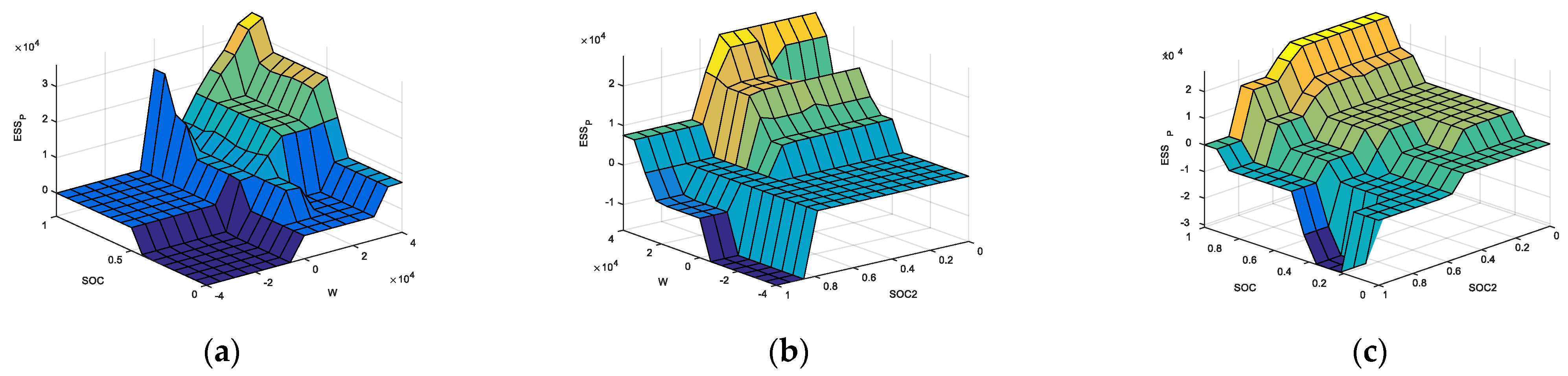
3.3. Sub-Fuzzy Controller

After the output power of the fuel cell is obtained by the main fuzzy controller, the Li-ion battery and super capacitor need to be responsible for the remaining part of energy management. By combining the characteristics of Li-ion battery and super capacitor, the sub-fuzzy controller reduces the impact of a high current on Li-ion batteries, prolongs their service life, and improves fuel economy.
Since fuel cells do not have the power to meet the high power demand of the FCHPS due to their limited power capacity, Li-ion batteries or super capacitors are required to provide energy and the FCHPS needs to recover braking energy when braking. As a result of the above analysis, the sub-fuzzy controller is designed to solve the problem of vehicle dynamics and energy recovery.
The sub-fuzzy controller is a three-input, single-output fuzzy controller with the input variables being the Li-ion battery SOC, the super capacitor SOC, and the residual power W, obtained after control by the main fuzzy controller, and the output variable being the Li-ion battery output power. The input variable of the sub-fuzzy controller is controlled by the main fuzzy controller and the resulting residual power W is designed with seven states, namely {negative large, negative small, zero, small, medium, large, and very large}; the fuzzy input variables are {ZZZ, ZZ, Z, L, M, H, and HH}, which include two modes of braking and driving. To reduce the high-current impact on the Li-ion battery when recovering braking energy, the energy recovery range of 0–40 kW is designed and divided into two intervals for recovering larger (20–40 kW) and smaller (0–20 kW) energy. Considering that the capacity of the Li-ion battery is larger than that of the super capacitor, five states are designed for the Li-ion battery and four states are designed for the super capacitor. The Li-ion battery states are {very low, low, medium, high, and very high} and the fuzzy input variables are {XL, L, M, H, and XH}; the super capacitor states are {very low, low, medium, and high} and the fuzzy input variables are {XL, L, M, and H}. The designed fuzzy control rules for the main fuzzy controller are shown in Table 3. The meaning of the sub-fuzzy control rule is:
6.
When the brake energy recovered by FCHPS is larger (ZZZ), the super capacitor SOC is smaller than the Li-ion battery SOC. The super capacitor can withstand the high-current shock, so the super capacitor recovers most of the energy and the Li-ion battery recovers energy as Z1. The total power expression is:
{ P f c = 0 P n = P B η D C / D C 1 + P C η D C / D C 2
where P n is the difference between the FCHPS demand power and the main fuzzy controller output.
7.
When the FCHPS recovers braking energy as ZZ and the super capacitor SOC is smaller than the Li-ion battery SOC, the super capacitor recovers most of the energy and the Li-ion battery does not recover energy. The total power expression is:
{ P f c = 0 P n = P C η D C / D C 2
When the super capacitor SOC is larger than the Li-ion battery SOC, the Li-ion battery recovers most of the energy and the super capacitor recovers a small portion of the energy. The total power expression is:
{ P f c = 0 P n = P B η D C / D C 1 + P C η D C / D C 2
8.
When the input power of the sub-fuzzy controller is small (L) and the super capacitor SOC is smaller than the Li-ion battery SOC, the output power of the super capacitor is Z. The remaining power is provided by the Li-ion battery. The total power expression is:
P B η D C / D C 1 = P n
When the super capacitor SOC is larger than the Li-ion battery SOC, the output power of the Li-ion battery is Z and the remaining power is provided by the super capacitor. The total power expression is:
P C η D C / D C 2 = P n
9.
When the input power of the sub-fuzzy controller is medium (M) and the super capacitor SOC is smaller than the Li-ion battery SOC, the output power of the Li-ion battery is M. The total power expression is:
M η D C / D C 1 + P C η D C / D C 2 = P n
When the super capacitor SOC is larger than the Li-ion battery SOC, the output power of the Li-ion battery is L. The super capacitor can better provide instantaneous energy and, therefore, provide most of the residual power support. The total power expression is:
L η D C / D C 1 + P C η D C / D C 2 = P n
10.
The sub-fuzzy controller that has a large input power (H, HH) turns on three energy sources simultaneously to supply energy to the whole vehicle when the input power is large and great. To ensure high charging and discharging efficiency in Li-ion batteries and super capacitors, the SOC of both batteries and super capacitors should be kept between 0.4 and 0.8. The total power expression is:
P B η D C / D C 1 + P C η D C / D C 2 = P n
The sub-fuzzy controller input affiliation function is shown in Figure 7. The same Mamdani inference method is used for fuzzy inference and the area center of gravity method is used to transform the vectors into unit values for defuzzification. Figure 8 shows the output power surface of the Li-ion battery.

4. Experiments and Analysis

Simulation experiments are conducted to verify the effectiveness and superiority of the dual fuzzy control proposed in this paper. The power, energy consumption economy, and performance degradation of the whole vehicle are analyzed by simulation experiments.

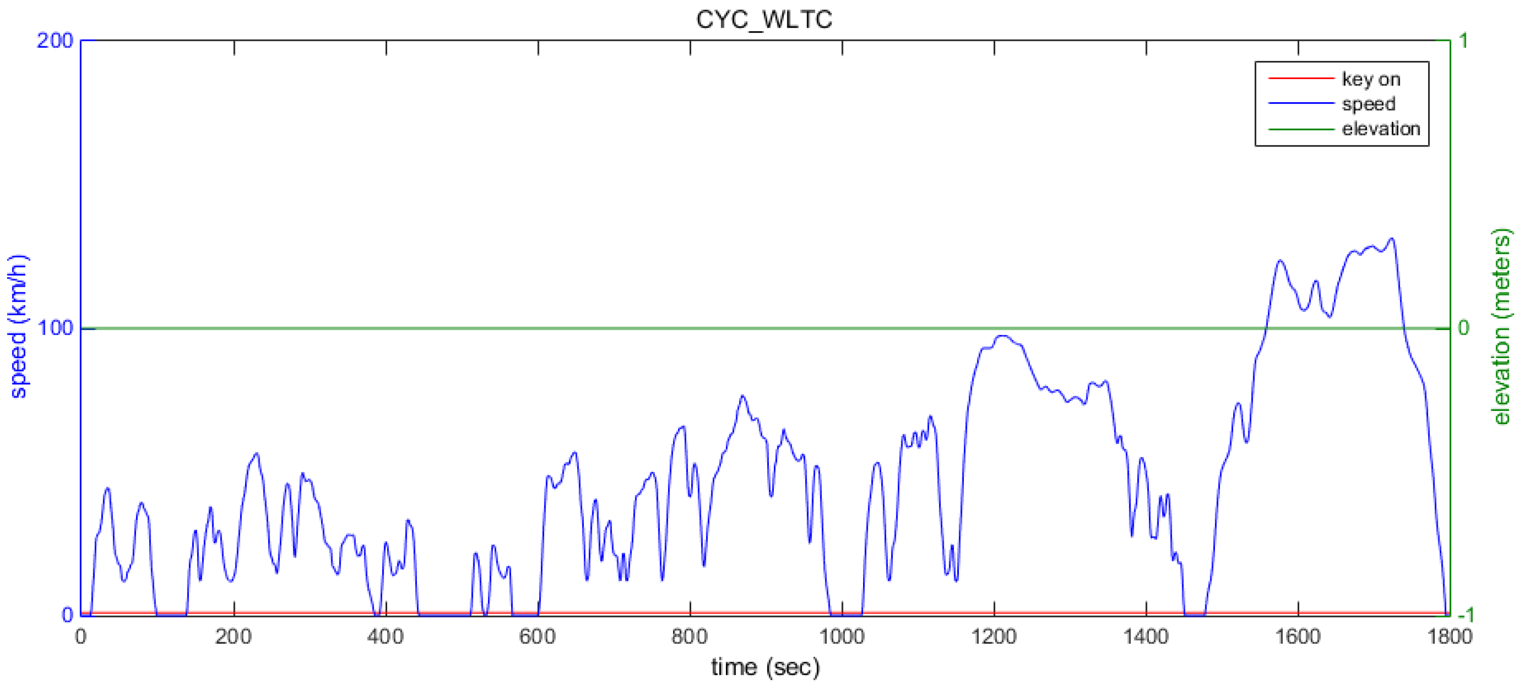
4.1. Simulation Conditions

Selection

The vehicle model built in this paper is mainly driven on urban and suburban roads, so the WLTC working condition is chosen for the simulation study, which is mainly for light vehicles, and the data obtained from the simulation under this working condition are more in line with the actual. A schematic diagram of the WLTC working condition is shown in Figure 9.

4.2. Simulation Model Building

In this paper, SIMULINK in MATLAB is used in conjunction with ADVISOR software to build the simulation platform. Among them, SIMULINK is used to model the dual fuzzy control strategy in the fuel cell hybrid system, as shown in Figure 10. The input of the main fuzzy controller is the whole vehicle demand power and Li-ion battery SOC. Fuel cell systems need an on/off condition, so when the fuel cell output is zero in the main fuzzy control, the fuel cell system is off.
The FCHPS studied in this paper contains three energy sources, but the fuel cell model in the ADVISOR software contains only two energy sources, so a secondary development of the ADVISOR software is required, with the following steps:
  • Change the whole vehicle M file, add the super capacitor model, and rename it.
  • Light up the second energy source in ADVISOR input interface and add super capacitor configuration information through the vehicle configuration data file “all menus. mat”.
  • Modify multiple M files related to the main page and add the modified model data.
  • Modify the super capacitor model parameters. Modify the names of all output variables in the model with the prefix ess2 to avoid data errors when using a super capacitor and Li-ion battery.
  • Associate the modified model file with the whole vehicle configuration file.

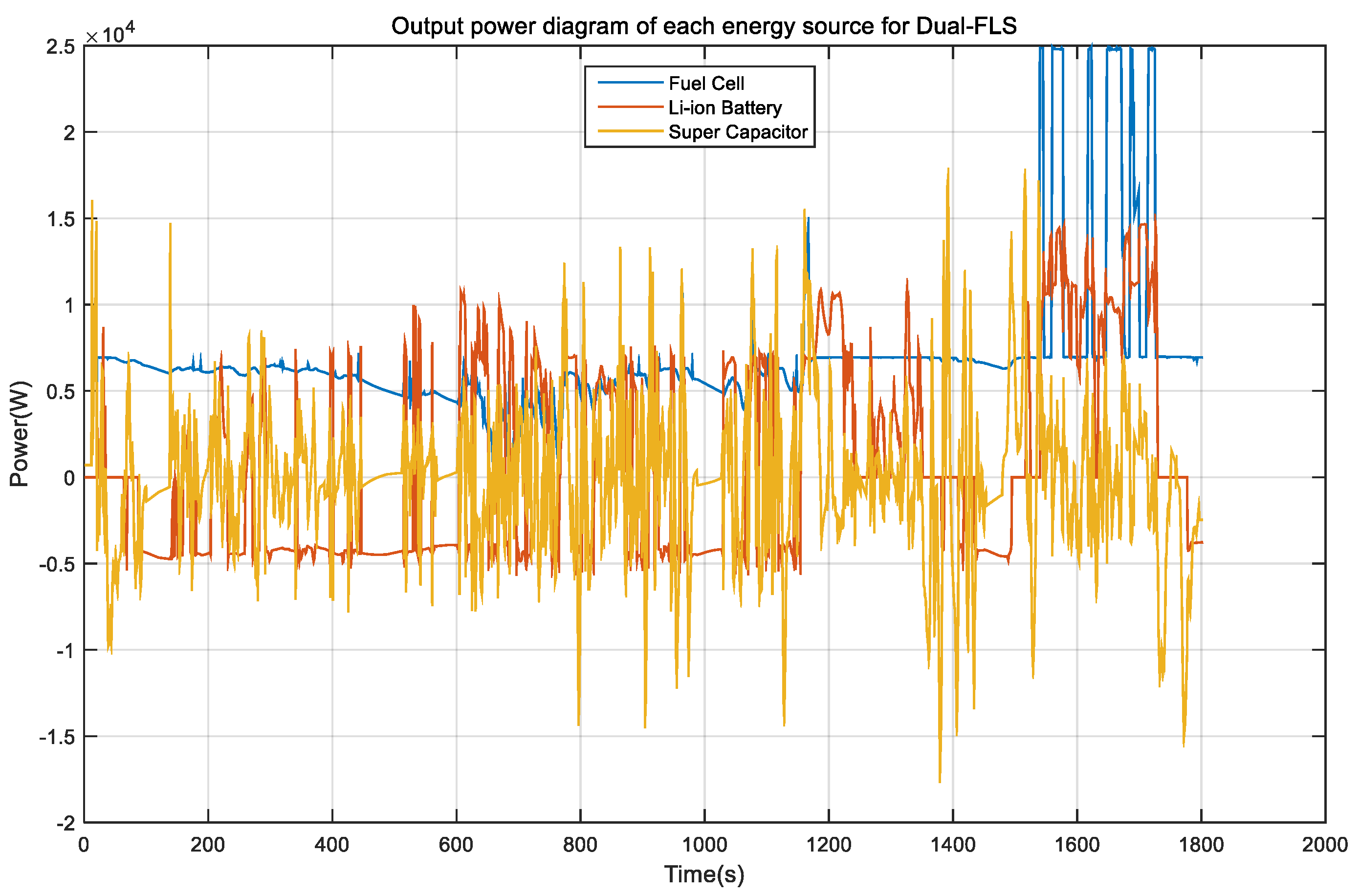
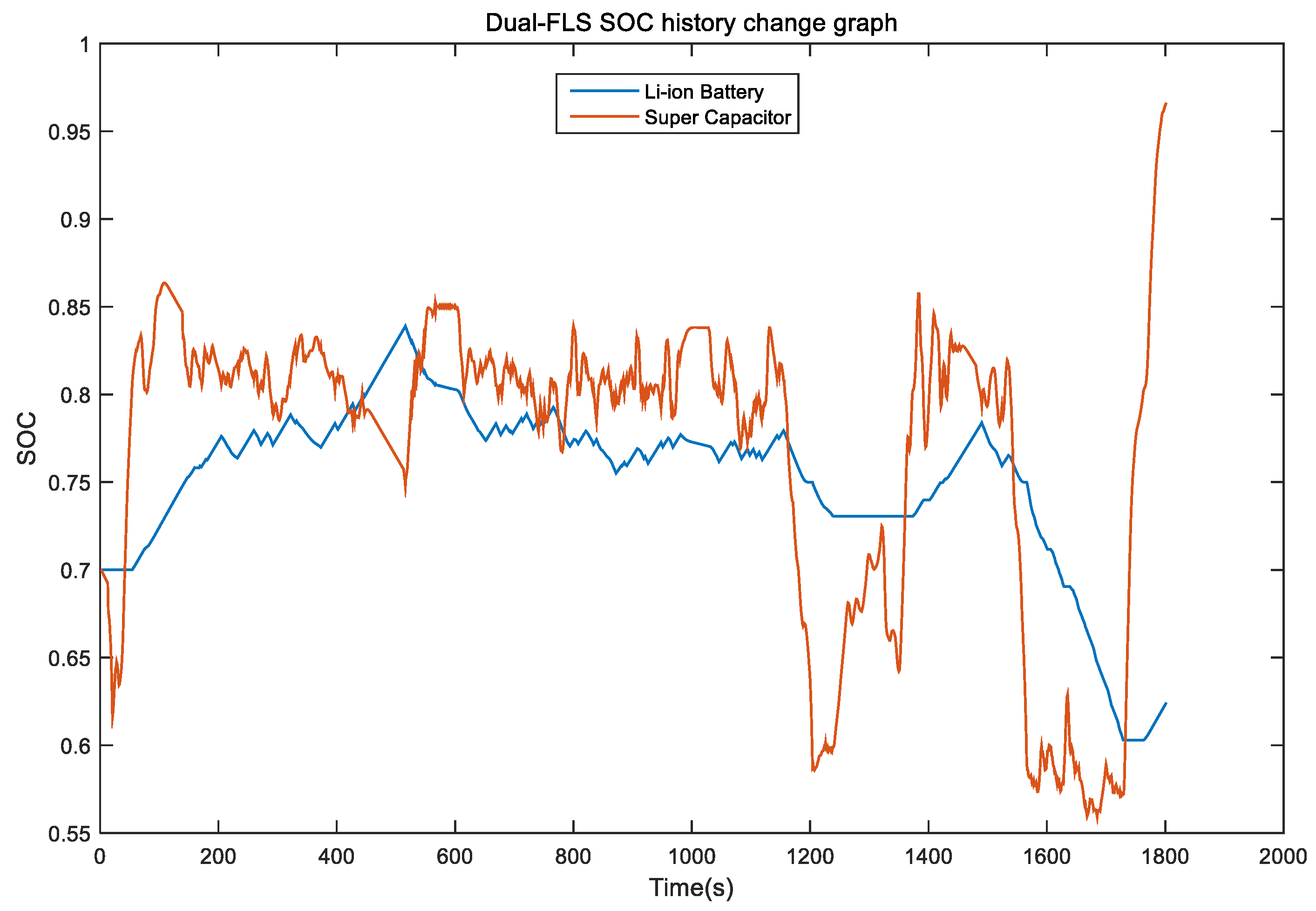
4.3. Simulation Analysis of Dual Control Strategy

Through the simulation model built for experiments, the output power of each energy source of the FCHPS controlled by the dual fuzzy control strategy proposed in this paper is shown in Figure 11. As can be seen from the figure, the fuel cell is the main energy source, its output is relatively smooth, and the number of starts and stops is only one during the whole operation, which is conducive to the service life of the fuel cell; to keep the fuel cell operating in the high-efficiency zone, the steady-state power is provided by the Li-ion battery and the transient power is provided by the super capacitor during high power demand. As shown in Figure 11, at 1600 s, the whole vehicle demand power increases and the output power of both Li-ion battery and super capacitor increases. Super capacitors can better provide peak power during acceleration, with the role of “peak shaving and valley filling”, effectively reducing the burden of fuel cells and Li-ion batteries. When braking, the super capacitor performs energy recovery first and recovers high power energy, which is in line with the super capacitor’s characteristic of taking in more high-frequency components. When the super capacitor SOC is high, the Li-ion battery starts to recover energy and the recovered energy is limited to 5 kW, which is beneficial to its service life.
According to Figure 12, the SOC curve of Li-ion batteries under this EMS does not fluctuate much and there are no obvious high-power recycling situations, which is beneficial to the service life of Li-ion batteries. When the FCHPS brakes, the Li-ion battery and super capacitor SOC rise, as shown in Figure 12. According to the output of each energy source and the SOC of each energy source, the control effect is in accordance with the fuzzy control rules.
The hydrogen consumption rate for the whole operating conditions is 51.4 L/100 km under the control of the strategy proposed in this paper.

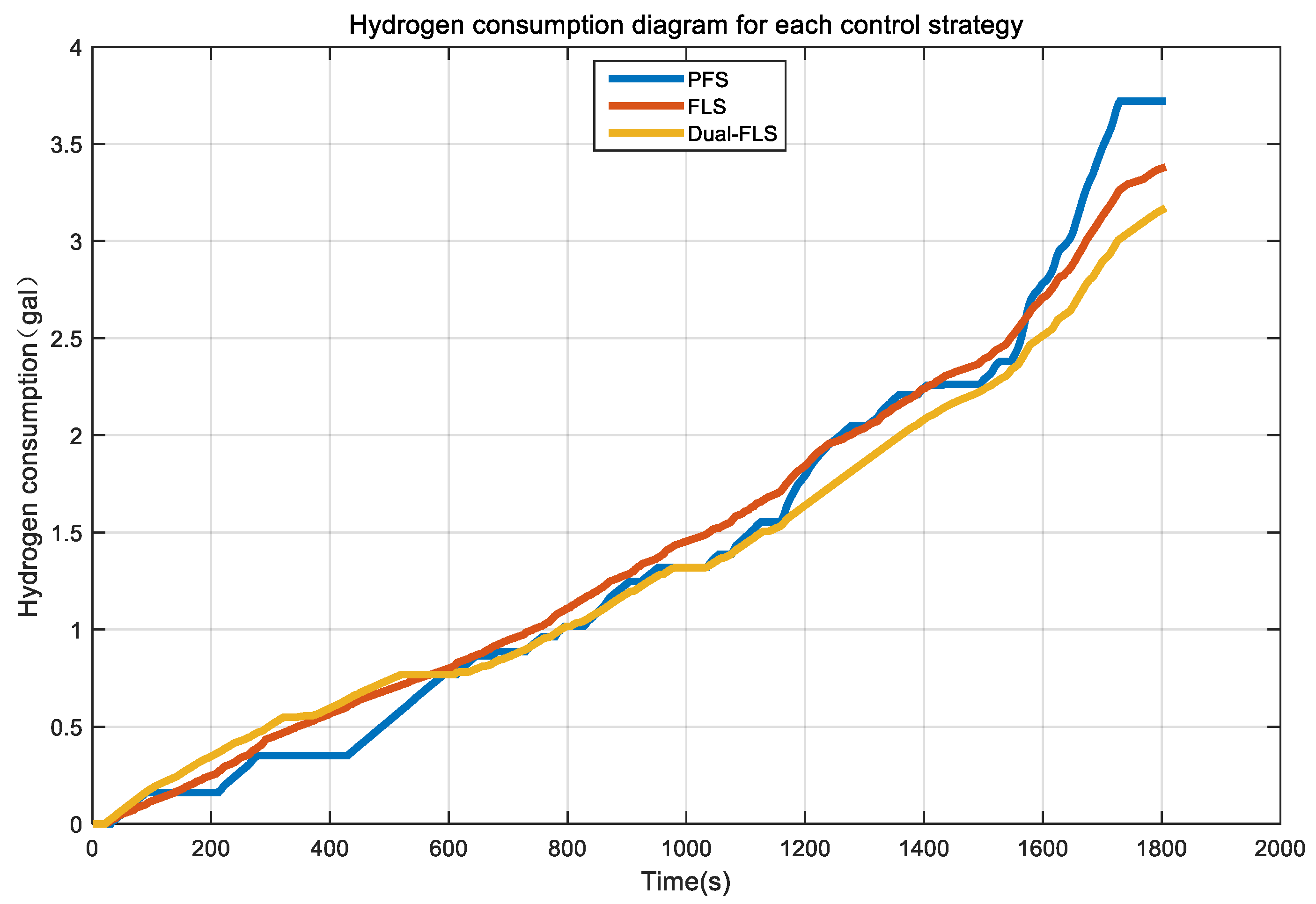
4.4. Control Strategy Simulation Comparison Analysis

The hydrogen consumption variation in the control strategy is proposed in this paper and compared with the power following control strategy and the single fuzzy control strategy, as shown in Figure 13. According to the figure, under the entire WLTC condition, the hydrogen consumption rate for the control strategy in this paper is 51.4 L/100 km, while the power following control strategy and single fuzzy control strategy consumes 55.2 L/100 km and 54.9 L/100 km, respectively. Clearly, this paper’s control strategy has better economics.
Based on a life analysis of each energy source, more stable output power and fewer switches and times are beneficial to fuel cell service life. In Figure 14a, the power following fuel cell system has longer on and off times. This leads to a lower hydrogen consumption before 1000 s and the hydrogen consumption increases after 1000 s, as power demand increases; based on Table 4, the fuel cell under EMS control has the fewest switches and times, which is beneficial to its service life, compared to the fuel cell under dual fuzzy control. As illustrated in Figure 14b, the recovered energy size of Li-ion battery with double fuzzy control strategy is smaller than other EMSs. The average current of Li-ion batteries under the single fuzzy control strategy is 13.4 A, while that of Li-ion batteries under the double fuzzy control strategy is 14.8 A. The average current of the Li-ion battery under this EMS control is minimized, which is beneficial to the service life of the Li-ion battery.

5. Conclusions

In this paper, a multi-energy-source hybrid power system vehicle with fuel cell + Li-ion battery + super capacitor is used as the research object and the FCHPS model is established by resetting the ADVISOR loading file. A dual fuzzy control strategy is proposed to simplify the complex problem of energy distribution from multiple energy sources and the logic of its control becomes simple and clear. With the objectives of reducing the fuel consumption of the whole vehicle, reducing the number of fuel cell starts and stops, and reducing the current inrush of the Li-ion battery, the main fuzzy controller and the sub-fuzzy controller jointly control the whole vehicle energy distribution. The results show that, compared with the single fuzzy control strategy and power following control strategy, the dual fuzzy control strategy control has advantages in fuel economy, the fuel cell switch-on and switch-off times are reduced, and the Li-ion battery is subjected to lower average current, which is beneficial to the fuel cell and Li-ion battery life. The disadvantage is that the energy management strategy in this paper is in the simulation verification stage and the control effect needs to be verified on a real car later.

Author Contributions

Conceptualization, J.L. and W.L.; methodology, J.L. and W.L.; software, J.L.; validation, J.L.; formal analysis, J.L.; investigation, J.L.; data curation, J.L.; writing—original draft preparation, J.L.; writing—review and editing, J.L., W.L., D.H. and H.L.; supervision, W.L., D.H. and H.L. All authors have read and agreed to the published version of the manuscript.

Funding

This research was funded by the National Natural Science Foundation of China, grant number 62263001; the Natural Science Foundation of Guangxi, grant number 2020GXNSFDA238011; the Open Fund Project of Guangxi Key Laboratory of Automatic Detection Technology and Instruments, grant number YQ21203; and the Independent Research Project of Guangxi Key Laboratory of Auto Parts and Vehicle Technology, grant number 2020GKLACVTZZ02.

Data Availability Statement

Not applicable.

Conflicts of Interest

The authors declare no conflict of interest.

References

  1. Miranda, M.; Banakar, P.; Gunnal, G.; Kumar, V.K.K. Robust Voltage Control of Improved Floating Interleaved Boost Converter for Photovoltaic Systems. In Proceedings of the 2020 5th International Conference on Computing, Communication and Security (ICCCS), Patna, India, 14–16 October 2020. [Google Scholar]
  2. Editorial Department of China Journal of Highway and Transport. Review on China’s Automotive Engineering Research Progress: 2017. China J. Highw. Transp. 2017, 30, 1–197. [Google Scholar] [CrossRef]
  3. Sykes, M.; Axsen, J. No free ride to zero-emissions: Simulating a region’s need to implement its own zero-emissions vehicle (ZEV) mandate to achieve 2050 GHG targets. Energy Policy 2017, 110, 447–460. [Google Scholar] [CrossRef]
  4. Chen, M.; Hua, Q.; Zhang, H.; Sui, Z.; Li, L. Research on Energy Management System of Fuel Cell/Battery Hybrid Electric Vehicle. J. Qingdao Univ. (Eng. Technol. Ed.) 2018, 33, 21–27. [Google Scholar] [CrossRef]
  5. Bauman, J.; Kazerani, M. A Comparative Study of Fuel-Cell–Battery, Fuel-Cell–Ultracapacitor, and Fuel-Cell–Battery–Ultracapacitor Vehicles. IEEE Trans. Veh. Technol. 2008, 57, 760–769. [Google Scholar] [CrossRef]
  6. Wang, H. Study on Energy Management Strategy of Medium Fuel Truck Power System. Master’s Thesis, Taiyuan University of Technology, Taiyuan, China, 2021. [Google Scholar] [CrossRef]
  7. Sun, Y.; Xia, C.; Yin, B.; Han, J.; Gao, H.; Liu, J. Energy Management Strategy of Fuel Cell Electric Vehicle. J. Jilin Univ. (Eng. Technol. Ed.) 2022, 9, 59244–59254. [Google Scholar] [CrossRef]
  8. Fu, Z.; Li, Z.; Si, P.; Tao, F. A Hierarchical Energy Management Strategy for Fuel Cell/Battery/Supercapacitor Hybrid Electric Vehicles. Int. J. Hydrog. Energy 2019, 44, 22146–22159. [Google Scholar] [CrossRef]
  9. Zhang, M.; Yang, Y.; Luo, Y.; Li, L. Fuel Cell Vehicle Energy Management Strategy Based on Fuzzy Logic. Electr. Autom. 2020, 42, 50–53. [Google Scholar]
  10. Gao, D.; Jin, Z.; Lu, Q. Energy Management Strategy Based on Fuzzy Logic for A Fuel Cell Hybrid Bus. J. Power Sources 2008, 185, 311–317. [Google Scholar] [CrossRef]
  11. Koteswararao, K.V.; Srinivasulu, G.N.; Venkateswarlu, V. A Review on Energy Allocation of Fuel Cell/Battery/Ultracapacitor for Hybrid Electric Vehicles. Int. J. Energy Res. 2018, 42, 4263–4283. [Google Scholar]
  12. Wu, Y. Research on Energy Management and Optimal Control of Fuel Cell Hybrid Power Vehicle. Master’s Thesis, North University of China, Taiyuan, China, 2021. [Google Scholar] [CrossRef]
  13. Erdinc, O.; Vural, B.; Uzunoglu, M. A Wavelet-fuzzy Logic Based Energy Management Strategy for A Fuel Cell/Battery/Ultra-capacitor Hybrid Vehicular Power System. J. Power Sources 2009, 194, 369–380. [Google Scholar] [CrossRef]
  14. Zhang, W.; Wan, W.; Zhang, Z.; Liu, Q.; Ouyang, N. Analysis of Hybrid Energy Management Strategy forFuel Cell Vehicle. J. Foshan Univ. (Nat. Sci. Ed.) 2021, 39, 1–8. [Google Scholar] [CrossRef]
  15. Zhang, J. Study on Energy Management Strategy of Fuelcell-Battery-Supercapacitor Hybrid Bus. Master’s Thesis, Jilin University, Zhuhai, China, 2018. [Google Scholar]
  16. Li, X.; Wang, Y.; Yang, D.; Chen, Z. Adaptive Energy Management Strategy for Fuel Cell/Battery Hybrid Vehicles using Pontryagin’s Minimal Principle. J. Power Sources 2019, 440, 227105. [Google Scholar] [CrossRef]
  17. Fletcher, T.; Thring, R.; Watkinson, M. An Energy Management Strategy to concurrently optimise fuel consumption & PEM fuel cell lifetime in a hybrid vehicle. Int. J. Hydrog. Energy 2016, 41, 21503–21515. [Google Scholar]
  18. Wang, Y.; Yu, Q.; Wang, X.; Sun, F. Adaptive Optimal Energy Management Strategy of FuelCell Vehicle by Considering Fuel Cell Performance Degradation. J. Traffic Transp. Eng. 2022, 22, 190–204. [Google Scholar] [CrossRef]
  19. Li, W.; Zheng, C.H.; Xu, D.Z. Research on Energy Management Strategy of Fuel Cell Hybrid Vehicles Based on Deep Reinforcement Learning. J. Integr. Technol. 2021, 10, 47–60. [Google Scholar] [CrossRef]
  20. Yu, Z. Elementary Vehicle Dynamics, 5th ed.; Machine Press: Beijing, China, 2009; pp. 19–20. [Google Scholar]
  21. Ruan, Y.; Zhan, Y. Research on Optimization of Hierarchical Energy Management Strategy for Fuel Cell Vehicles. Electron. Meas. Technol. 2021, 44, 1–7. [Google Scholar] [CrossRef]
  22. Zeng, X.; Gong, W.; Li, X. ADVISOR 2002 Electric Vehicle Simulation and Redevelopment Application; Machine Press: Beijing, China, 2014; pp. 44–49. [Google Scholar]
  23. Tang, S. A Research on Optimization Theory of MAMDANI Fuzzy Systems. Master’s Thesis, Central South University, Changsha, China, 2005. Available online: https://kns.cnki.net/KCMS/detail/detail.aspx?dbname=CDFD9908&filename=2006037248.nh (accessed on 16 May 2006).
  24. Wang, W.; Shi, H.; Li, Y. Weighted Centroid Localization Algorithm Based on Mamdani Fuzzy Theory. Comput. Sci. 2015, 42, 101–105+121. [Google Scholar]
Figure 1. FCHPS structure diagram.
Machines 10 00880 g001
Figure 2. Vehicle force diagram for uphill driving.
Machines 10 00880 g002
Figure 3. Fuel cell power–power curve.
Machines 10 00880 g003
Figure 4. Dual fuzzy control framework diagram.
Machines 10 00880 g004
Figure 5. Affiliation function of the input variables in the main−fuzzy controller. (a) Required power affiliation function, (b) Li−ion battery SOC affiliation function.
Machines 10 00880 g005
Figure 6. Fuel cell output power surface diagram.
Machines 10 00880 g006
Figure 7. Sub−fuzzy controller’s input variable affiliation function. (a) Power W affiliation function, (b) Li−ion battery SOC affiliation function, (c) super capacitor SOC affiliation function.
Machines 10 00880 g007
Figure 8. Li−ion battery output power surface diagram. (a) W−SOC output surface, (b) W−SOC2 output surface, (c) SOC−SOC2 output surface.
Machines 10 00880 g008
Figure 9. WLTC working speed diagram.
Machines 10 00880 g009
Figure 10. Simulation model of dual fuzzy control strategy. (a) Simulation model of main−fuzzy controller, (b) simulation model of sub−fuzzy controller.
Machines 10 00880 g010
Figure 11. Output power diagram of each energy source under dual fuzzy control.
Machines 10 00880 g011
Figure 12. SOC variation in Li-ion battery and super capacitor under dual fuzzy control strategy.
Machines 10 00880 g012
Figure 13. Variation in hydrogen consumption under each control strategy.
Machines 10 00880 g013
Figure 14. Comparison of different control strategies. (a) Fuel cell output power diagram under each control strategy, (b) Li−ion battery current variation curve under each control strategy.
Machines 10 00880 g014
Table 1. Basic parameters of fuel cell vehicles.
PartsParametersParameter Value
Whole carQuality/ k g 1196
Windward area/ m 2 2
Air resistance coefficient C d 0.335
Tire rolling radius R / m m 478
MotorPeak power/ k W 83
Fuel CellMaximum power/ k W 50
Power Rating/ k W 30
Li-Ion BatteryMonomer capacity/ ( A h ) 80
Number of tandem30
Number of parallel connections3
Super CapacitorMonomer capacity/ F 9500
Number of tandem80
Number of parallel connections1
Monomer capacity/ F 9500
Table 2. Main fuzzy control rules table.
Preq
ZSSSSSMSHSMSHMHHH
SOCXLHSMMMSHMHHHHHH
LHSHSHSMSHSHSHHHHH
MSSSSSSSSSSSSSSSSSS
HSSSSSSSSSSSSMMM
XHZZZZZZZZZ
Table 3. Sub-fuzzy control rules table.
Soc1XLXLXLXLLLLLMMMMHHHHXHXHXHXH
Soc2XLLMHXLLMHXLLMHXLLMHXLLMH
wZZZZ1Z1Z1ZZZZ1Z1Z1ZZZZZZZZZZZZZZZZZ
ZZZ1Z1Z1Z1Z1Z1Z1Z1ZZZZZZZZ1ZZZZZZ
ZZZZ1Z1LZZ1ZZZLLZZ1MMLZ1HHMZ
LLZZZ1LLLZ1LLZZ1LLLLLLLL
MMZZZ1MZZZ1MMZZ1MMMZMMMM
HZZZZ1ZZZZLMZZMMMZHHHM
HHLLZZLLLZHHLLHHHHLHHHHML
Table 4. Results of different EMS controls.
EMS Fuel   Consumption   L / 100   k m Fuel Cell Switching TimesLi-ion Battery Average Current / A
PFS55.21814.8
FLS54.9913.4
Dual-FLS51.4112.8
Publisher’s Note: MDPI stays neutral with regard to jurisdictional claims in published maps and institutional affiliations.

