Article

Comparative Study of the Conventional Mathematical and Fuzzy Logic Controllers for Velocity Regulation

Division of Graduate Studies and Research, Tijuana Institute of Technology, Tijuana 22379, Mexico
*
Author to whom correspondence should be addressed.
Axioms 2019, 8(2), 53; https://doi.org/10.3390/axioms8020053
Submission received: 26 March 2019 / Revised: 17 April 2019 / Accepted: 26 April 2019 / Published: 1 May 2019
(This article belongs to the Special Issue Softcomputing: Theories and Applications)

Abstract

:
Currently, we are in the digital era, where robotics, with the help of the Internet of Things (IoT), is exponentially advancing, and in the technology market we can find multiple devices for achieving these systems, such as the Raspberry Pi, Arduino, and so on. The use of these devices makes our work easier regarding processing information or controlling physical mechanisms, as some of these devices have microcontrollers or microprocessors. One of the main challenges in speed control applications is to make the decision to use a fuzzy logic control (FLC) system instead of a conventional controller system, such as a proportional integral (PI) or a proportional integral-derivative (PID). The main contribution of this paper is the design, integration, and comparative study of the use of these three types of controllers—FLC, PI, and PID—for the speed control of a robot built using the Lego Mindstorms EV3 kit. The root mean square error (RMSE) and the settling time were used as metrics to validate the performance of the speed control obtained with the controllers proposed in this paper.

1. Introduction

In recent years, autonomous mobile robots have been used to perform a wide variety of important activities and specific functions. These robots are used to perform exploration tasks on other planets, monitor volcanic activities, study deep-water behavior, assemble cars, and support people’s surgeries, among many other activities. All these activities are carried out in conjunction with other disciplines and using new emerging technologies including the Internet of Things (IoT), as a tool or complement for the acquisition and transmission of data. From the place where the robot is located, the information obtained must be processed by an intelligent model (artificial intelligence) to give an answer or instructions to the autonomous robot.
There are several methods that are used in system control. The classic ones include proportional control (P), which determines the relation of the current error [1]; proportional integral control (PI), which generates a proportional correction of the errors as observed in [2,3,4,5]; and proportional integral derivative (PID), which determines the reaction time in which the error occurs. There are two types of forms in a control algorithm that decide on a particular control action—the open loop system, in which the parameters of the algorithms are preset and do not change while the system is running, and the closed loop system, in which there are sensors that measure the error between the desired state of the system and its real state. This error is used to decide on the action to take; thus, closed circuit control systems are used.
These controllers can be used to solve a problem when there is no knowledge of the process, when its objective is to obtain greater precision in the control of the system, and when related works in the literature can be observed [6,7,8].
In the literature, we can find works where the authors propose the use of other devices. For example, in [9,10,11,12], some works are presented, using raspberry pi to solve different problems, such as to track and monitor animal activities, to control a robotic arm, to classify and recognize animals, and to detect and classify arrhythmias. It is also recommended to read [13,14], where the authors propose the use of other devices in their work.
An alternative method is to use fuzzy logic control (FLC) algorithms based on fuzzy rules, and these systems have been widely used, as shown in [15,16,17,18,19,20]. A fuzzy control system contains rules, and these rules are expressed in terms of linguistic variables. FLC is now also widely used to solve any problem that contains the concept of knowledge-based fuzzy inference proposed by Zadeh in 1965 [21]. Unlike classical logic, where we have only true or false, a fuzzy inference system handles simple linguistic variables that adapt better to the real world, for example, minimum, maximum, etc. [22]. Fuzzy logic has been widely used, as shown in [23,24,25,26,27,28,29].
The era of robots has been very successful in recent years [30], with various types of robots in existence. In this case, the Lego Mindstorms EV3 is considered, which is the third generation of the set of robotics belonging to the Lego company. These robots have been used to solve certain problems, as shown in [31,32,33].
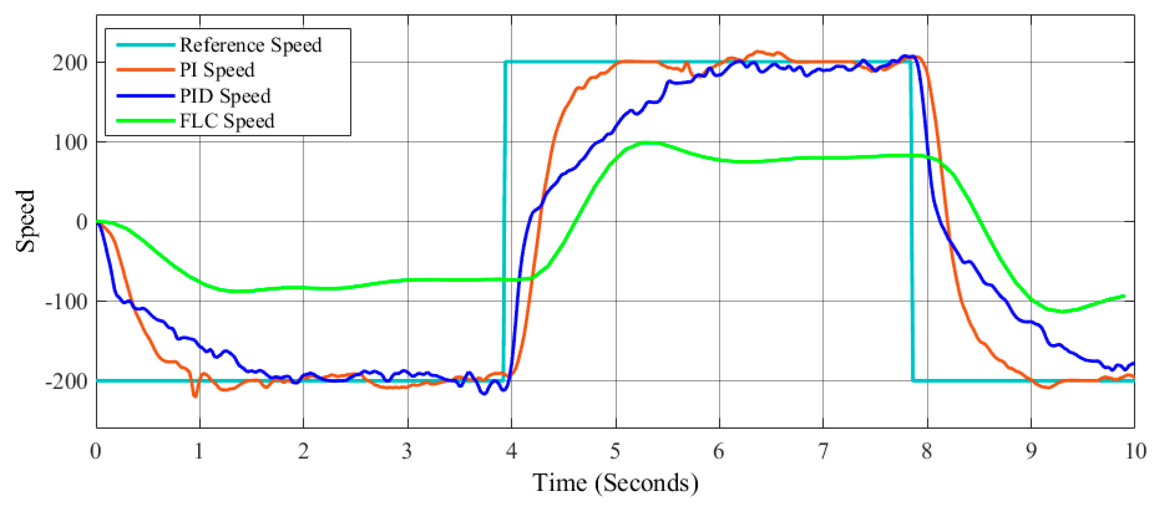
Today, it is difficult to make the decision about using a PID controller or an FLC system. In this paper, the three types of controls, called PI, PID, and FLC, are applied to the speed control of the Lego Mindstorms EV3, with the main objective being to achieve good speed control of the robot. Recently, these robots have been widely used, as shown in [34,35,36,37].
Different methods and techniques are used to find the best parameters for PI and PID controllers, such as the Ziegler Nichols method [38,39,40]. On the other hand, for FLC, there are evolutionary computation techniques to find the best parameters by means of a genetic algorithm [41,42,43,44,45]. However, in this case the values of the parameters of these controllers were found through trial and error.
The metrics used in this study are the integral of the squared error (ISE), the integral of the absolute value of error (IAE), the integral of the time-weighted squared error (ITSE), the integral of the time multiplied by the absolute value of error (ITAE), and the root mean square error (RMSE).
This paper is comprised of the following sections: Section 2, in which the mathematical model of the Lego Mindstorms EV3 is presented; Section 3, in which the case study is shown; Section 4, in which the simulations and results are shown; and, finally, Section 5, in which the conclusions are presented.

2. The Mathematical Model of the Lego Mindstorms EV3

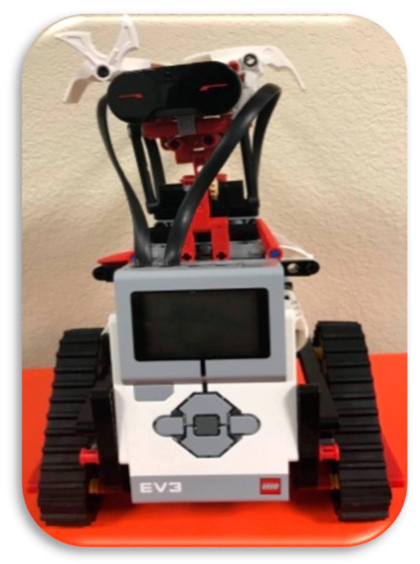
The Lego Mindstorms team is the most popular educational platform, since it has a relatively accessible cost; it is reusable, robust, and reconfigurable; and its modules are easy to use by students of all educational levels. In addition, the EV3 team contains all the elements or parts necessary to build a functional robot. It is widely used for educational purposes, as well as for research experiments in robotics. In this work we are using the Matlab language programming framework, this language facilitates the interaction with the motors for readings of the positions with respect to the reference.
This model has an operating system based on LINUX, with an ARM9 processor of 300 MHz, a RAM memory of 64 MB, a Flash memory of 16 MB, RJ12 connectors ports for sensors and motors, and USB 2.0 communication (in this case, we used this port for the connection of a USB wireless module for synchronization with the developed block model).
In this paper, a Lego Mindstorms EV3 robot has been used for the experiment. This robot has several characteristics including two large motors, a medium motor, and a programmable brick EV3, which is the control center and the power source of the robot, as well as a wireless card for the experiment and therefore could be assembled in different ways. The particular robot configuration in this case is shown in Figure 1.
The mathematical model for modeling the motor of the robot uses two fundamental laws of physics [46]: the first is Kirchhoff’s law based on the energy conservation and load of the electrical circuits, as shown in Equation (1); and the second is Newton’s law based on the mechanical equation, as shown in Equation (2).
L d i ( t ) d t = v i n ( t ) v e m f ( t ) R i ( t )
J d w ( t ) d t = T m ( t ) b w ( t )
where, Table 1 shows the description of each variable.

3. Case Study Used in This Work

Three different control methods to achieve the speed control of a Lego Mindstorms EV3 are used, and a closed circuit control systems is used [47,48,49,50]. 
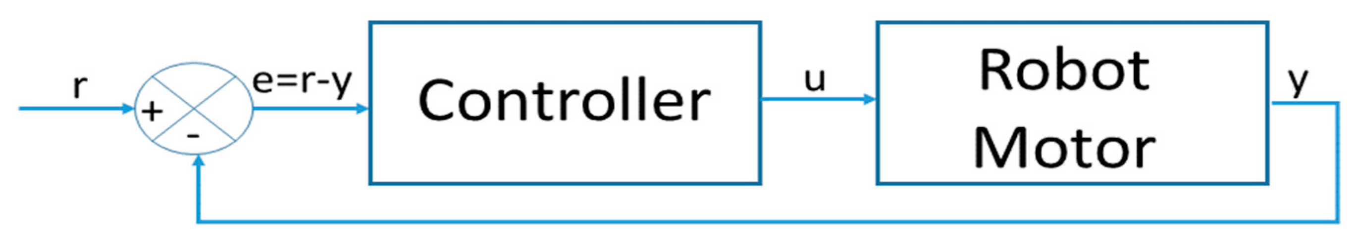
Figure 2 shows the general scheme of a closed loop control system.
The parameter denoted by r represents the reference value; the variable transformed into a control value is represented by u, and the y variable represents the output, which is calculated with the equation e = ry.
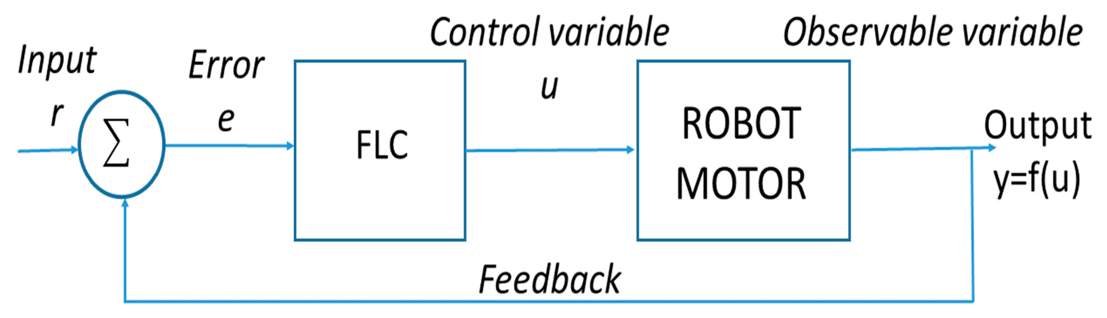
The first is a PI controller based on the Equation (3), the second is a PID controller based on the Equation (4), and the third is a fuzzy controller that is based on the theory of fuzzy sets with which the FLC control systems can be created. The general diagram of an FLC is shown in Figure 3.
r ( t ) = K p   e ( t ) + K i o t e ( t ) d t
where r is the controller output, t is the time, k p is the proportional gain, e is the error between the reference value and the system output, and d τ is the time derivative.
r ( t ) = K p   e ( t ) + K i   o t e   ( t ) d t + K d d e ( t ) d t
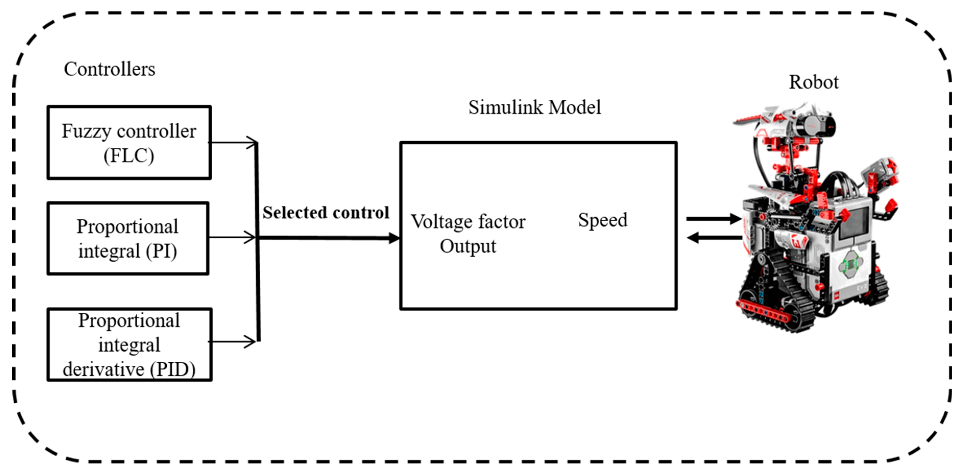
The Lego Mindstorms EV3 robot is shown in Figure 1, and a general illustration of the proposal is presented in Figure 4. The main challenge of this work was the synchronization between the controller and the robot in real time, and the methodology is as follows: a block model is developed with the help of Simulink, and the mathematical model of the Lego is codified. Afterwards, wireless synchronization is done with the Lego robot using an USB adapter; the values of the variables for the proposed controllers (FLC, PI, and PID) are added to perform the tests and observe the behavior of the robot.
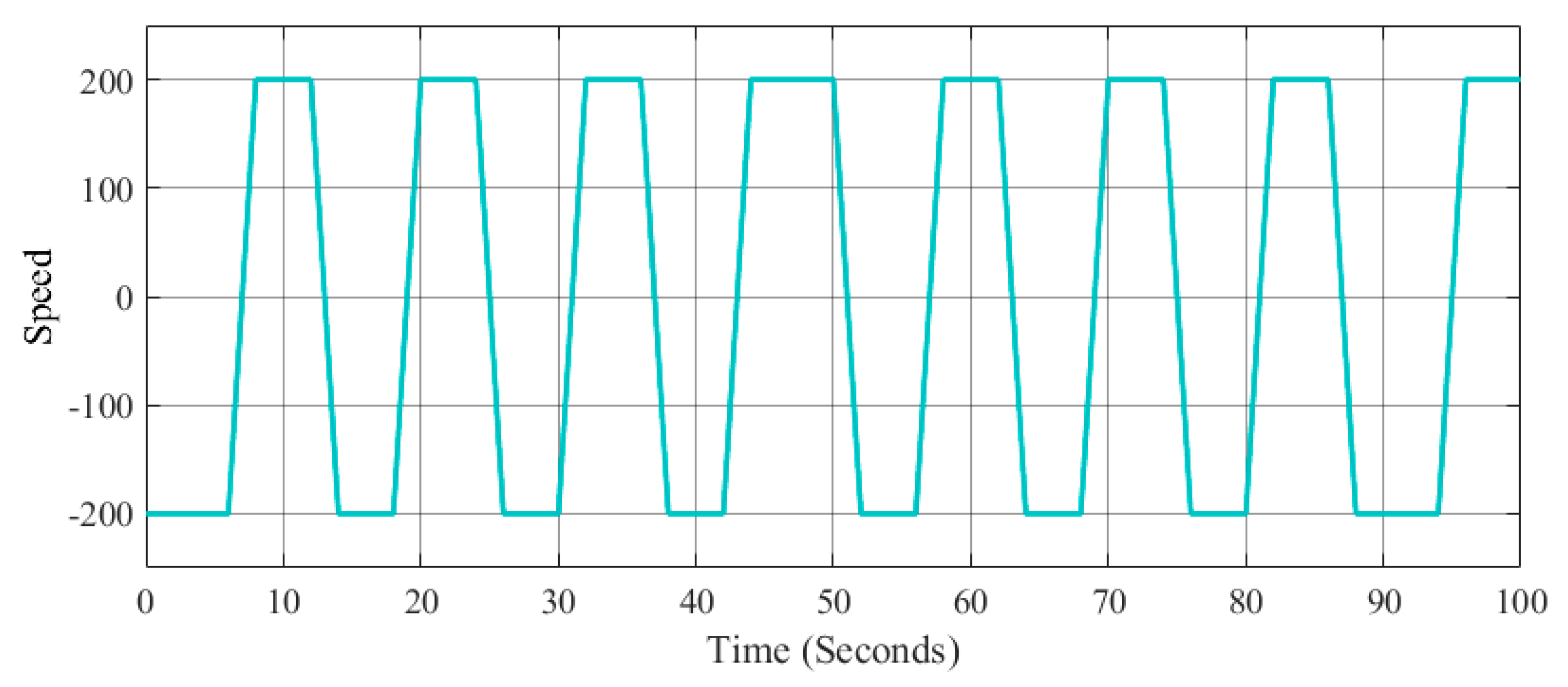
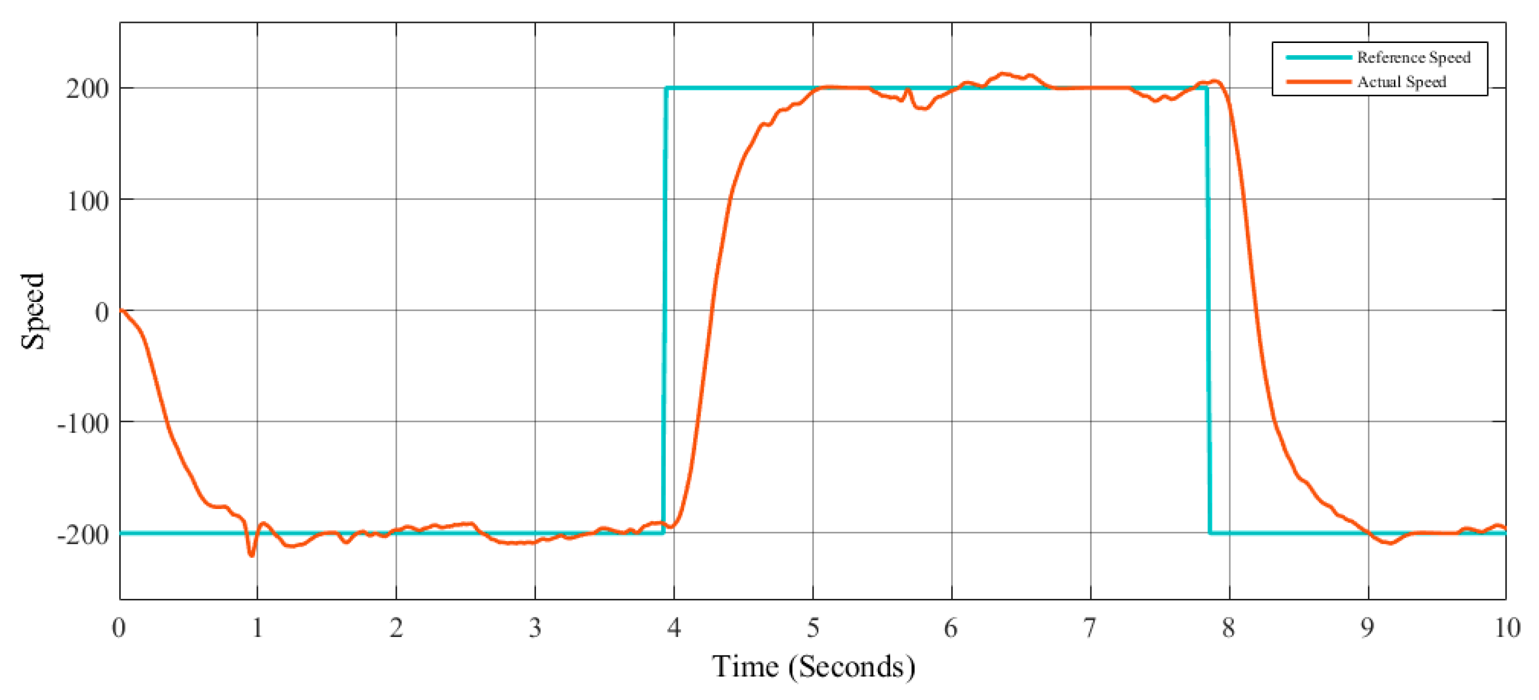
The main objective is to maintain control of the speed in the robot, and the tests are realized using one type of control (PI, PID, and FLC) for each test. The design of the controllers in this case was done by trial and error. The speed control was tested with two different speed signal references: a step and a signal generator for each method (PI, PID, and FLC). The step reference signal r(t) is given by Equation (5), where t is the sampling time; the signal generator is given by Equation (6), where the amplitude is 200; the frequency is 0.8; the waveform is square; and t is the simulation time.
r ( t ) = { 2 180 p i   t > 0 0   t 0
r ( t ) = A m p W a v e f o r m ( F r e q , t )
The objective function for FLC is the root mean square error (RMSE) that is represented in Equation (7), and the objective function for PI and PID controller is the Settling Time, although there are other control metrics that are also used, as follows: ISE (Integral of Squared error), IAE (Integral of the Absolute value of the Error), ITSE (Integral of Time-weighted Squared Error), and ITAE (Integral of the Time multiplied by the Absolute value of the Error), respectively, presented in Equations (8)–(11). The metrics used to measure the error in this work were selected based on works published in the literature; most of the authors and experts in the area recommend some of them in works related to control [17,34,36,37].
R M S E = 1 N   t = 1 N ( x t x ^ t ) 2
I S E = t = 1 N | ( x ( t ) x ^ ( t ) ) 2 |
I A E = t = 1 N | x ( t ) x ^ ( t ) |
I T S E = t = 1 N t   ( ( x ( t ) x ^ ( t ) ) 2 )
I T A E = t = 1 N t   ( x ( t ) x ^ ( t ) )

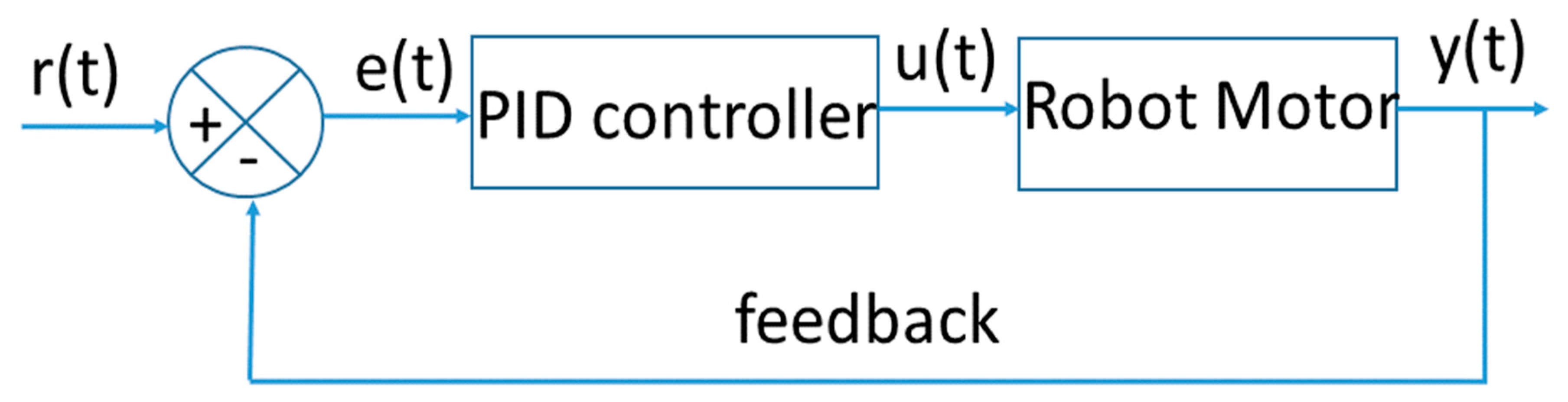
3.1. Proportional Integral Controller for the Lego Mindstorms EV3

The two aforementioned speed reference signals are applied to a PI controller model in order to achieve the speed control in the Lego Mindstorms EV3 robot. Figure 5 shows the diagram of this controller.
Where r(t) is the reference signal (step and signal generator); e(t) is the difference between the reference signal and the actual output signal y(t); u(t) is the controller output; and y(t) is the output, in this case the speed of the robot. The parameters used for speed control with the step reference signal are shown in Table 2, and the parameters used for speed control with the signal generator reference signal are shown in Table 3; the initial ranges for these cases are from −1 to 1, and in the tables the best parameters obtained for each reference are shown.

3.2. Proportional Integral Derivative Controller for Lego Mindstorms EV3

The PID controller model used to achieve the speed control of the Lego Mindstorms EV3 robot is illustrated in Figure 6.
In this case, the same speed reference signals mentioned above were used. The parameters used for speed control with the step reference signal are shown in Table 4, and the parameters used for speed control with the signal generator reference signal are shown in Table 5. The initial ranges for these cases are from −1 to 1, and in the tables the best parameters obtained for each reference are shown.

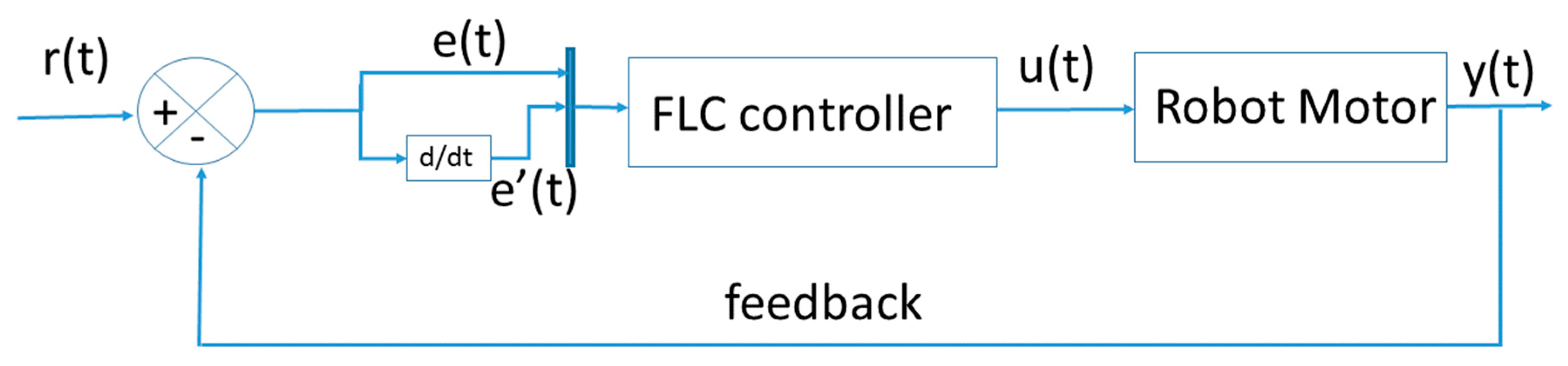
3.3. Fuzzy Logic Controller for the Lego Mindstorms EV3

A fuzzy logic controller is used in order to control the speed of the robot; also, the two speed reference signals were used in the above Equations (5) and (6). The FLC control model can be found in Figure 7.
The fuzzy system controller contains two inputs (the error e(t) and the error change e’(t)) and one output (the control signal (Voltage) y(t), see Figure 8); the error and the error change are calculated using Equations (12) and (13).
e ( t ) = r ( t ) y ( t )
e ( t ) = e ( t ) e ( t 1 )
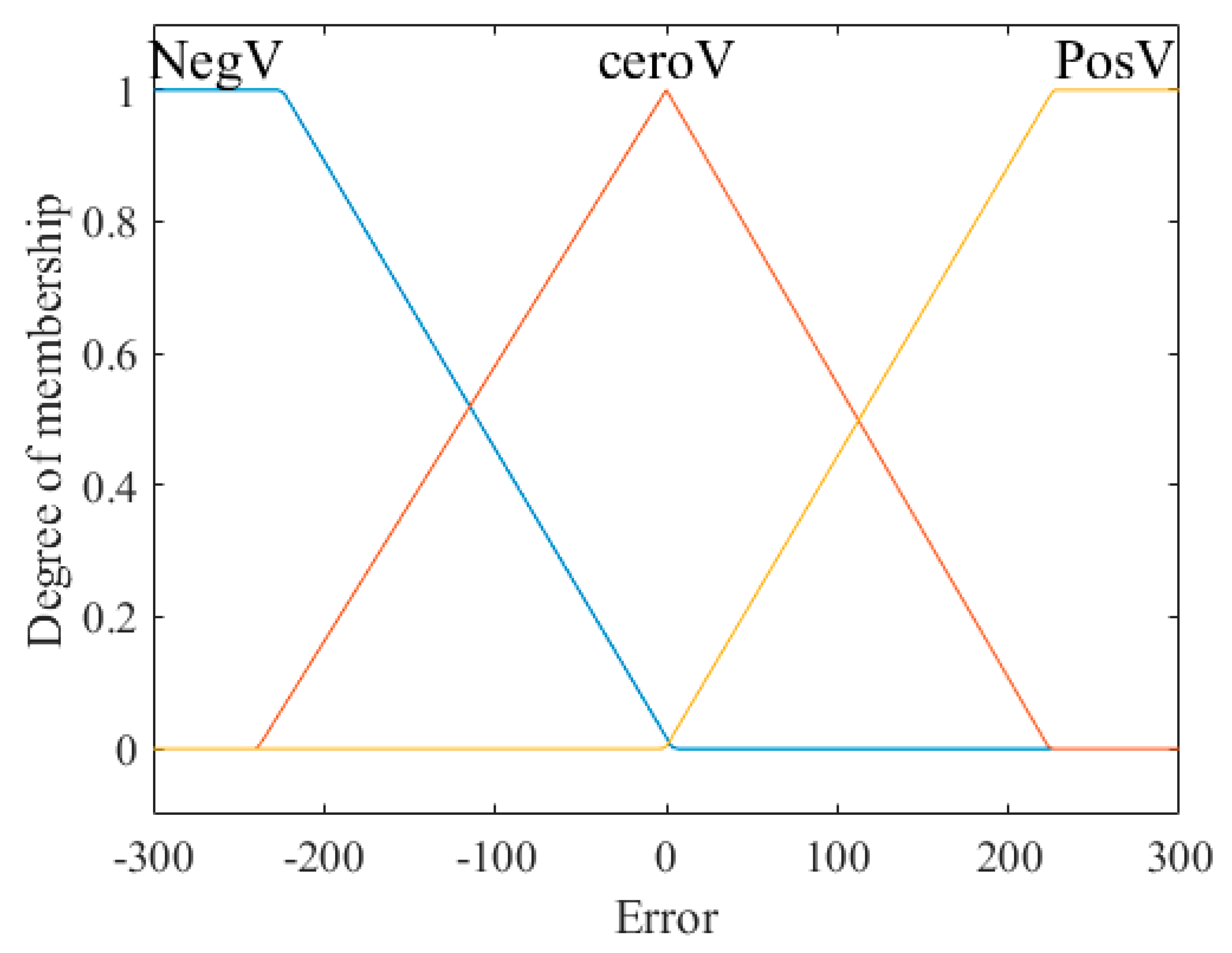
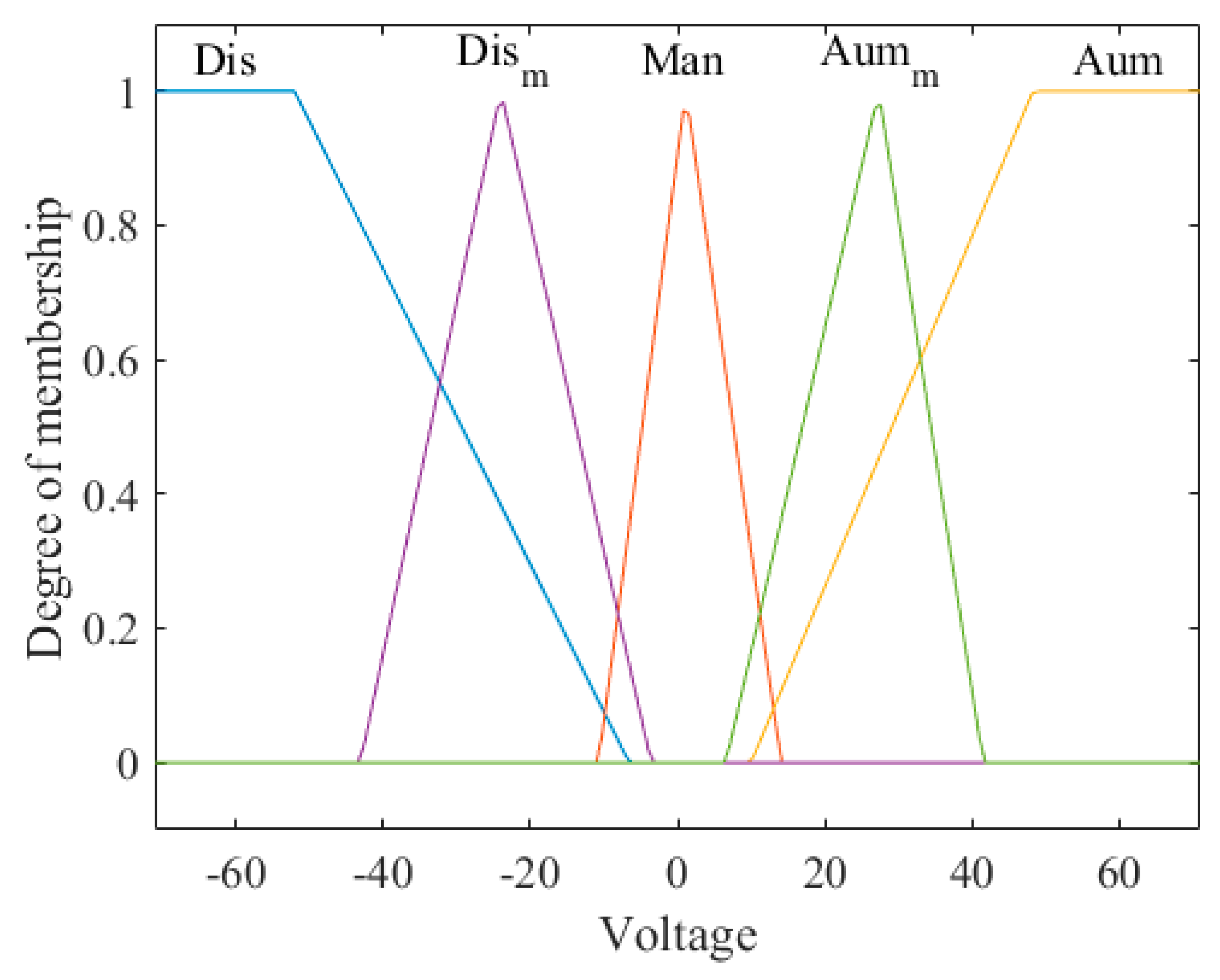
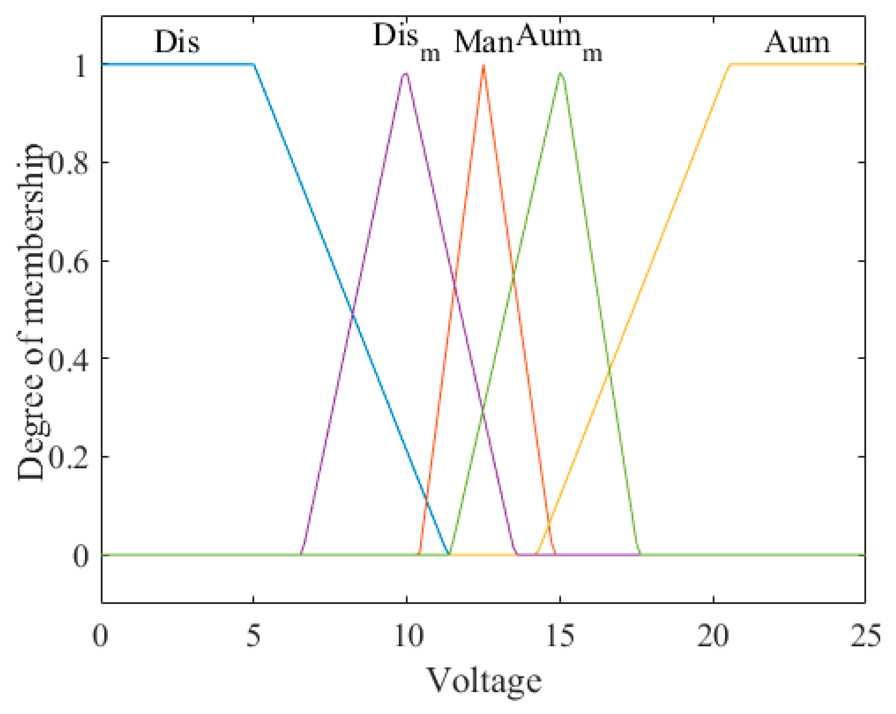
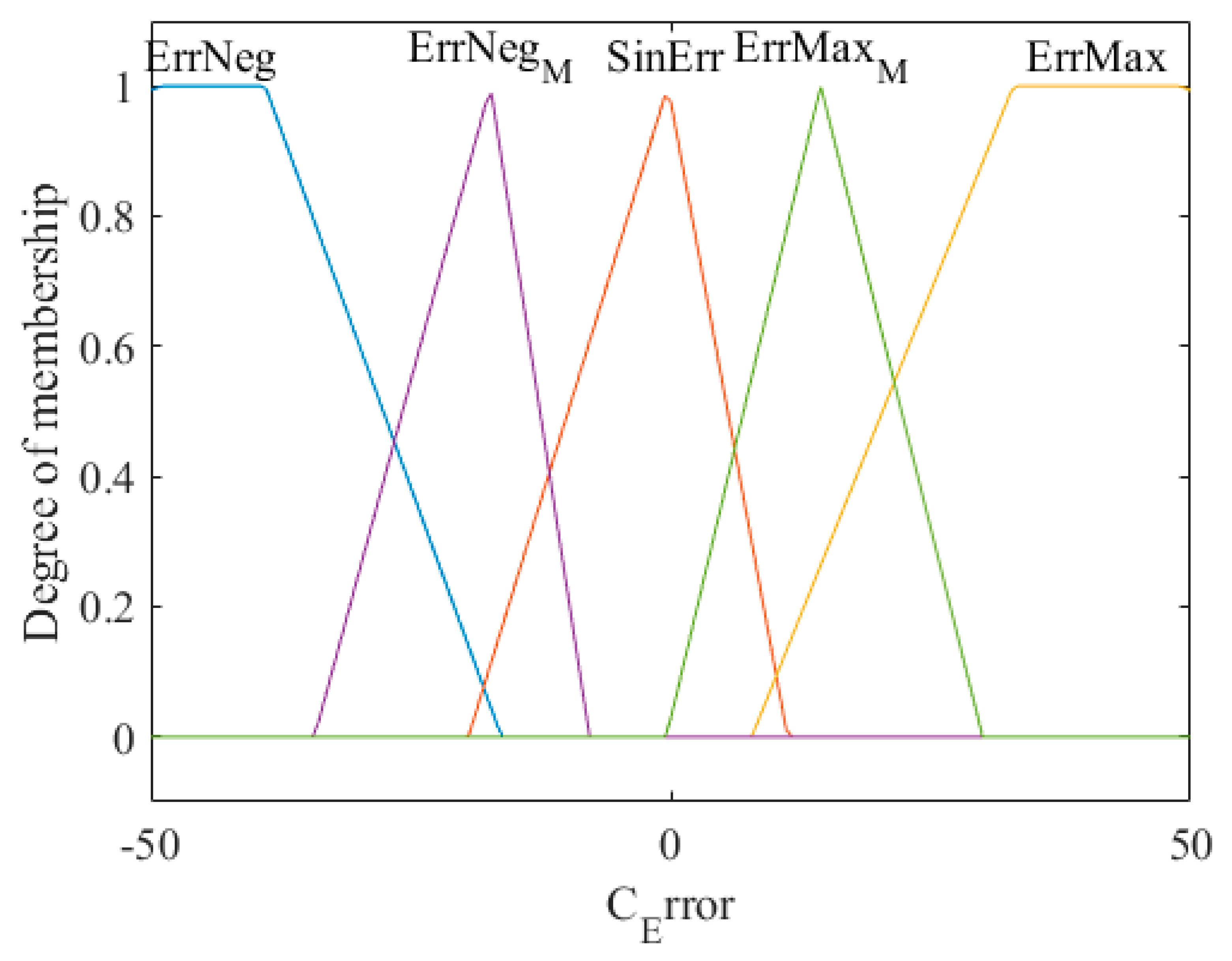
The inputs and output are granulated into trapezoidal and triangular membership functions, which were created with Equations (14) and (15), respectively. These membership functions of this type were used for the ease of integration in this control problem.
f ( x ; a , b , c , d ) = { 0 ,   x a x a b a ,   a x b 1 ,   b x c d x d c ,   c x d 0 ,   d x
f ( x ; a , b , c ) = { 0 ,   x a x a b a ,   a x b c x c b ,   b x c 0 ,   c x
The parameters of the membership functions for speed control with the step reference signal are presented in Table 6. The parameters of the membership functions for speed control with the signal generator reference signal are shown in Table 7. The FLC contains 15 rules, which are shown in Table 8.
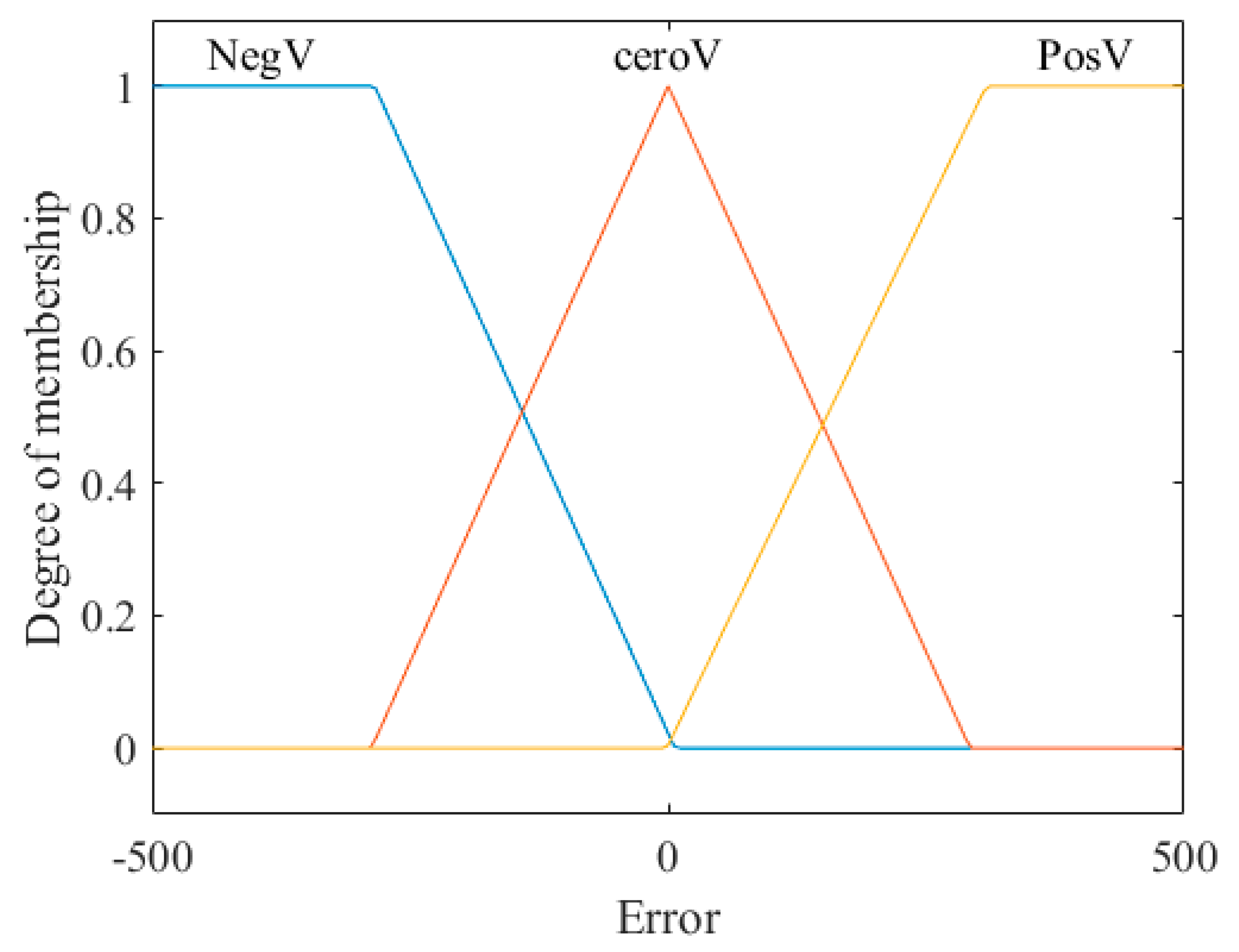
Table 6 shows the parameters of the triangular and trapezoidal membership functions used to achieve speed control with the step reference; it is important to mention that the values are obtained via the observations and experiences of experts in the area.
Figure 8, Figure 9 and Figure 10 show the inputs and output of the fuzzy system for the step speed reference, where input 1 is the error, input 2 is the change of the error, and the output is the voltage and its linguistic values.
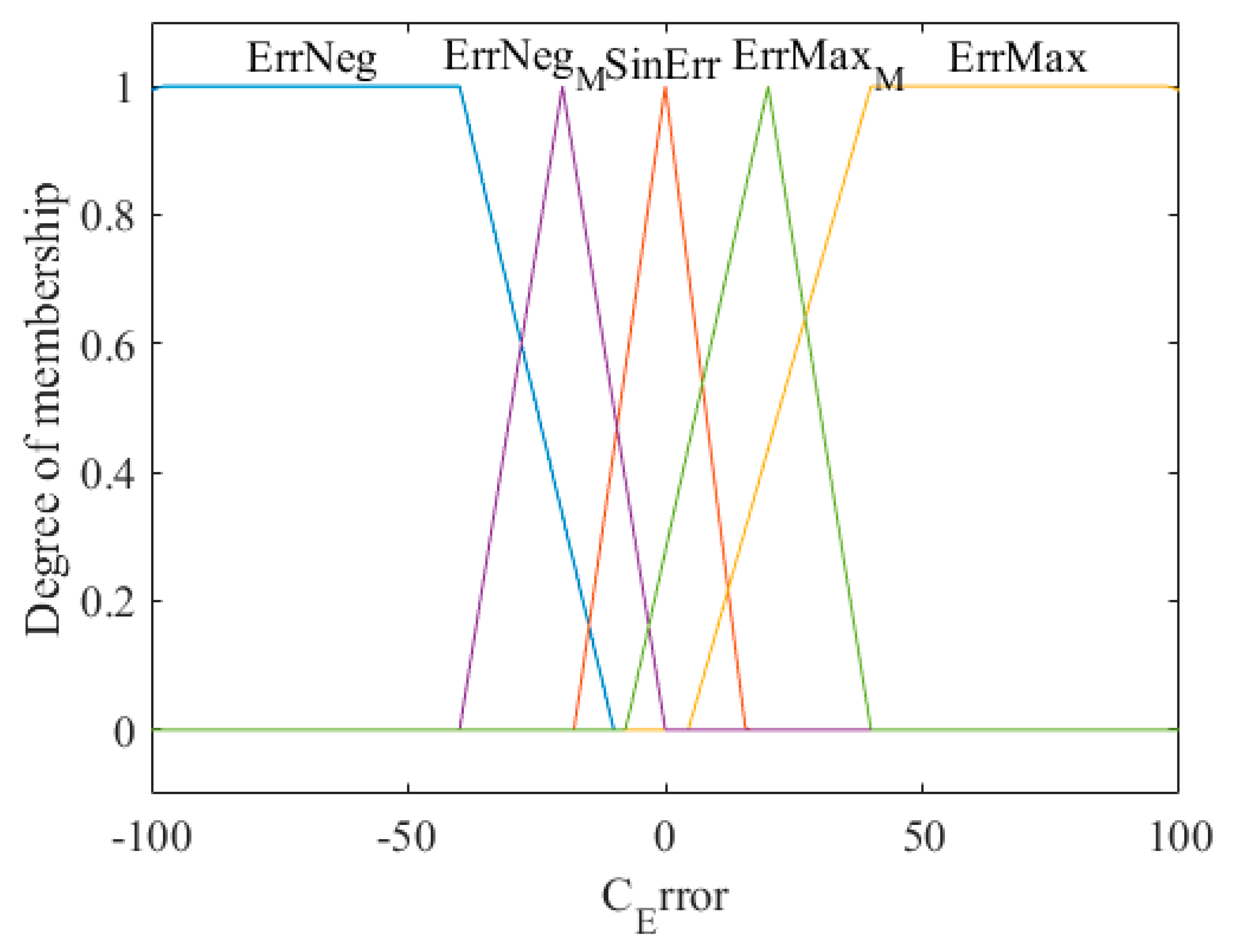
Table 7 shows the parameters of the triangular and trapezoidal membership functions used to achieve speed control with the signal generator reference; it is important to mention that the values are obtained via the observations and experiences of experts in the area.
Figure 11, Figure 12 and Figure 13 show the inputs and outputs of the fuzzy system for the signal generator speed reference, where input 1 is the error, input 2 is the change of the error, and the output is the voltage and its linguistic values.
Table 8 shows the combination of if-then fuzzy rules for the proposed controller used to control the motor speed of the Lego Mindstorms EV3.
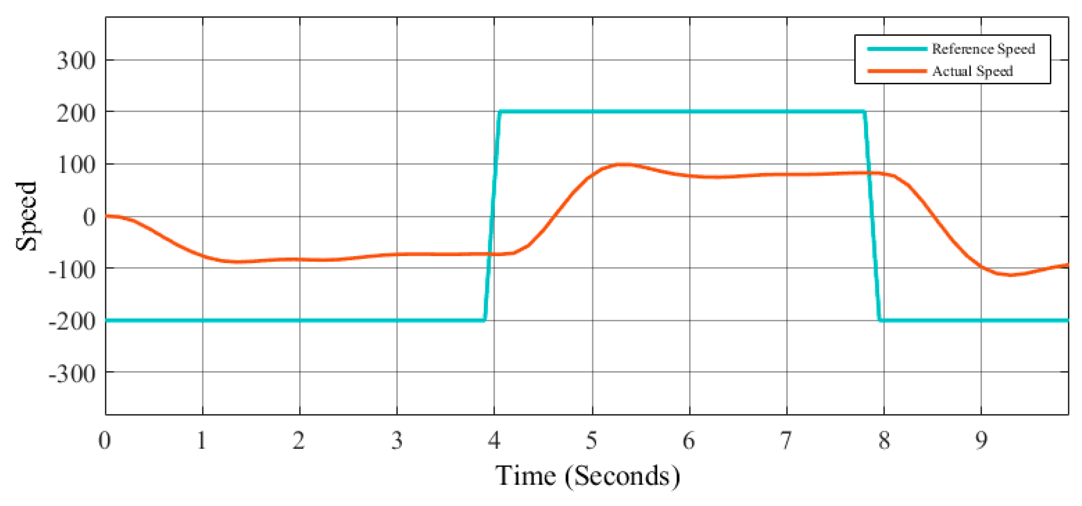
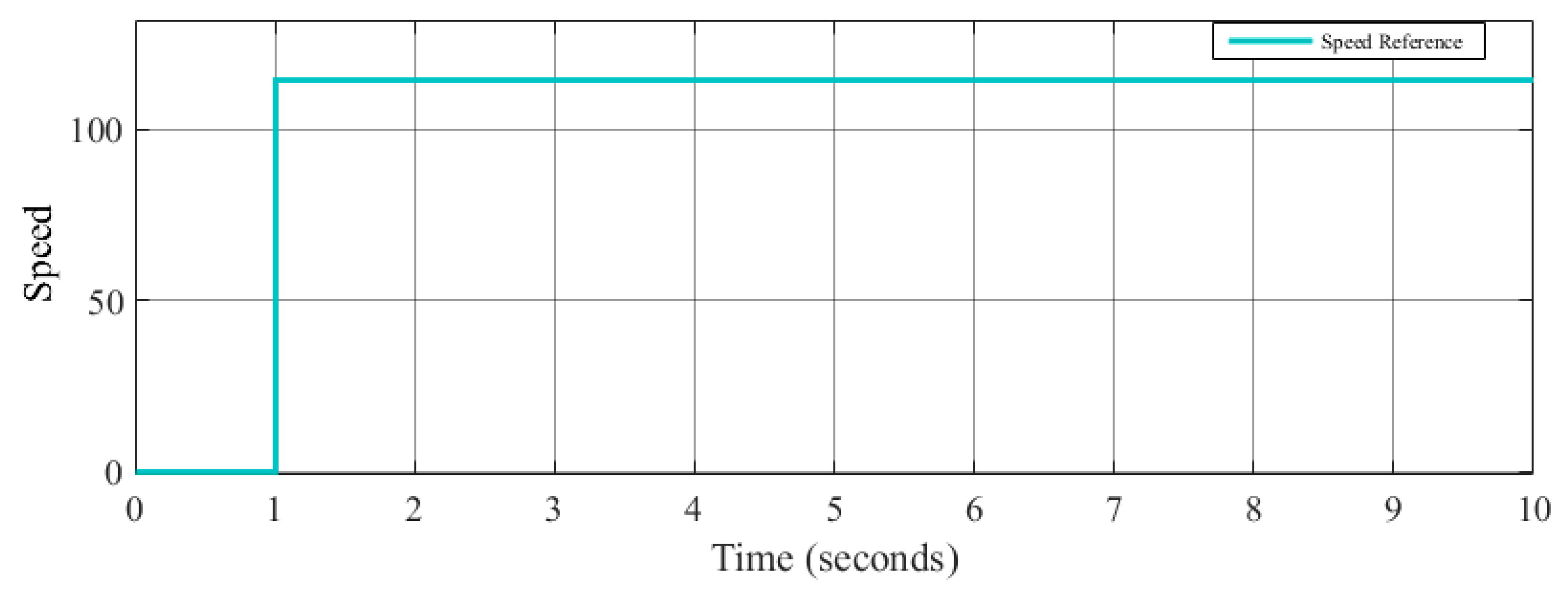
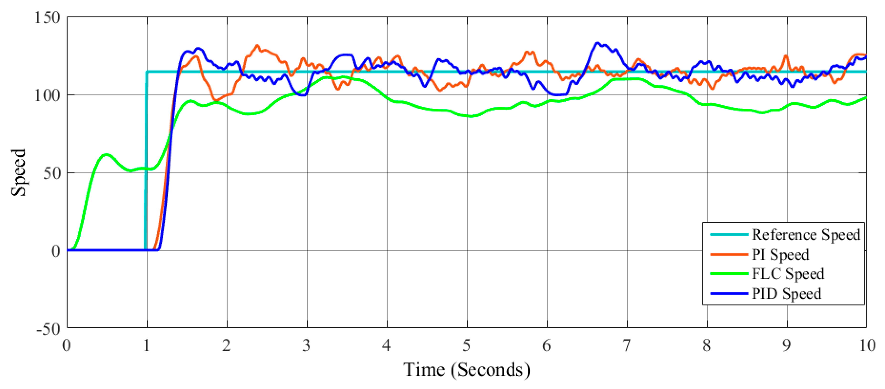
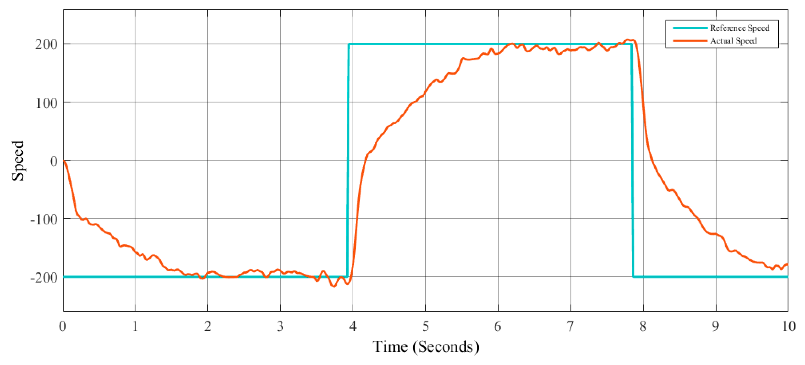
The speed step reference signal is illustrated in Figure 14, and the speed signal generator reference is illustrated in Figure 15, where the objective is to follow as close as possible the desired speed reference.

4. Simulations and Results

Different tests were carried out in order to find the results closest to the reference speed, while the robot physically maintained a good speed without overlap or sudden movements. In the following sections, the best results obtained by each speed reference are shown, and it is important to note that the adjustment of these parameters was done manually by trial and error.

4.1. Results of the Experimentation for Step Reference

Parameters were tested by trial and error using values −1 to 1 for the PI and PID controller, and the following tables show the errors of the best result obtained in the simulations for each PI, PID, and FLC controller for the step speed reference.
Table 9 and Table 10 show the results obtained when adjusting the parameters of the PI and PID controllers, respectively, for the speed reference of the step. In these tables we can find the results of the PI and PID controllers and the settling time that is the objective function in the case of these two controllers. The units of the errors shown in the following tables are radians/seconds.
Figure 16 and Figure 17 show the simulations obtained from the PI and PID controllers, respectively, for the speed reference of the step; the blue line represents the reference speed, and the orange line represents the actual speed.
Once the behavior of the robot in the PI and PID controllers was validated, it was possible to obtain the ranges to achieve the speed control in the fuzzy controller for the step reference speed; the ranges varied from −1000 to 20 for the inputs and outputs mentioned in the Section 3.3.
Table 11 shows the results obtained by manually adjusting the parameters of the fuzzy logic controller for the speed reference of the step, and RMSE error obtained is shown. Figure 18 shows the best simulation obtained.
Figure 19 indicates the performance curves for the step speed reference obtained with the three proposed controllers.

4.2. Results of the Experimentation for Signal Generator Reference

Parameters were tested by trial and error using values −1 to 1 for the PI and PID controller, and the following tables show the errors of the best result obtained in the simulations for each PI, PID, and FLC controller for the signal generator speed reference.
Table 12 and Table 13 show the results obtained when adjusting the parameters of the PI and PID controllers, respectively, for the speed reference of the signal generator. In these tables we can find the results of the PI and PID controllers and the settling time, which is the objective function in the case of these two controllers.
Figure 20 and Figure 21 show the simulations obtained from the PI and PID controllers, respectively, for the speed reference of the signal generator; in this case, the blue line represents the reference speed and the orange line represents the actual speed.
Once the behavior of the robot in the PI and PID controllers was validated, it was possible to obtain the ranges to achieve the speed control in the fuzzy controller for the signal generator reference speed; the ranges varied from −1000 to 20 for the inputs and outputs mentioned in the Section 3.3.
Table 14 shows the results obtained by manually adjusting the parameters of the fuzzy logic controller for the speed reference of the signal generator; RMSE error obtained is shown. Figure 22 shows the best obtained simulation.
Figure 23 indicates the performance curves for the signal generator speed reference obtained with the three proposed controllers.

5. Conclusions

The main objective of this work was the design and integration of the following controllers (PI, PID, and FLC) applied and modeled in a robot built using the Lego Mindstorms kit version EV3. The authors of this work consider it important to mention to the reader that our approach and contribution was not the minimization of the errors obtained, but to apply and integrate different types of control systems. The design of these controllers was performed manually with the help of an expert in the area. The speed control was performed with two different speed reference signals: the step and signal generators. The results obtained with the PI and PID controllers in both cases were better than the FLC controller; however, in real time the robot managed to maintain a stable speed without frights, which was the objective of this work using the controllers proposed in this paper. It is important to highlight that the objective of the authors in this work was the adaptation in real time between Matlab–Simulink with the Lego Mindstorms EV3 and the observation of the behavior of the robot with the applied controllers. In future work, we consider it necessary to use optimization meta-heuristics or other intelligent search techniques to find the best values for the controllers in order to improve the results shown in this paper.

Author Contributions

Conceptualization, O.C. and F.V.; methodology, O.C.; software, C.P. and C.C; validation, C.P., C.C and O.C; formal analysis, F.V.; investigation, F.V.; resources, O.C.; data curation, C.C.; writing—original draft preparation, C.P. and C.C; writing—review and editing, O.C. and F.V.; visualization, O.C.; supervision, F.V.; project administration, F.V.; funding acquisition, O.C.

Funding

This research was funded by Consejo Nacional de Ciencia y Tecnología, grant number 122.

Acknowledgments

We thank the Division of Graduate Studies and Research of Tijuana Institute of Technology and the financial support provided by CONACYT contract grant 122.

Conflicts of Interest

The authors declare that there is no conflict of interest regarding the publication of this paper.

References

  1. Kiam Heong, A.; Chong, G.; Yun, L. PID control system analysis, design, and technology. IEEE Trans. Control Syst. Technol. 2005, 13, 559–576. [Google Scholar] [CrossRef]
  2. Raviraj, V.S.C.; Sen, P.C. Comparative study of proportional-integral, sliding mode, and fuzzy logic controllers for power converters. IEEE Trans. Ind. Appl. 1997, 3, 518–524. [Google Scholar] [CrossRef]
  3. Cheng, Y.; Nan, Q.; Wang, R.; Dong, T.; Tian, Z. Fuzzy proportional integral derivative control of a radiofrequency ablation temperature control system. In Proceedings of the 2017 10th International Congress on Image and Signal Processing, BioMedical Engineering and Informatics (CISP-BMEI), Shanghai, China, 14–16 October 2017; pp. 1–5. [Google Scholar]
  4. Colonna, P.; Casati, E.; Trapp, C.; Mathijssen, T.; Larjola, J.; Turunen-Saaresti, T.; Uusitalo, A. Organic Rankine Cycle Power Systems: From the Concept to Current Technology, Applications, and an Outlook to the Future. J. Eng. Gas Turbines Power 2015, 137, 100801. [Google Scholar] [CrossRef]
  5. Ibrahim, Z.; Levi, E. A comparative analysis of fuzzy logic and PI speed control in high-performance AC drives using experimental approach. IEEE Trans. Ind. Appl. 2002, 38, 1210–1218. [Google Scholar] [CrossRef]
  6. Bingol, M.C.; Akpolat, Z.H.; Koca, G.O. Robust Control of a Robot Arm Using an Optimized PID Controller. In Mechatronics 2017; Březina, T., Jabłoński, R., Eds.; Springer International Publishing: Cham, Switzerland, 2018; Volume 644, pp. 484–492. [Google Scholar]
  7. Bhandari, A.S.; Chaudhuri, A.; Roy, S.; Negi, S.; Sharad, M. Single chip self-tunable N-input N-output PID control system with integrated analog front-end for miniature robotics. In Proceedings of the 2017 IEEE 14th International Conference on Networking, Sensing and Control (ICNSC), Calabria, Italy, 16–18 May 2017; pp. 109–114. [Google Scholar]
  8. Sa-ngiamvibool, W. Optimal Fuzzy Logic Proportional Integral Derivative Controller Design by Bee Algorithm for Hydro-Thermal System. IEEE Trans. Ind. Inform. 2017. [Google Scholar] [CrossRef]
  9. Balogh, Z.; Bízik, R.; Turčáni, M.; Koprda, Š. Proposal for Spatial Monitoring Activities Using the Raspberry Pi and LF RFID Technology. In Wireless Communications, Networking and Applications; Zeng, Q.-A., Ed.; Springer: New Delhi, India, 2016; Volume 348, pp. 641–651. [Google Scholar]
  10. Xu, L. Remote Control and Monitoring System of Robotic Arm Using Raspberry Pi. In Recent Developments in Mechatronics and Intelligent Robotics; Deng, K., Yu, Z., Patnaik, S., Wang, J., Eds.; Springer International Publishing: Cham, Switzerland, 2019; Volume 856, pp. 642–648. [Google Scholar]
  11. Popat, P.; Sheth, P.; Jain, S. Animal/Object Identification Using Deep Learning on Raspberry Pi. In Information and Communication Technology for Intelligent Systems; Satapathy, S.C., Joshi, A., Eds.; Springer: Singapore, 2019; Volume 106, pp. 319–327. [Google Scholar]
  12. Valliappan, C.A.; Balaji, A.; Thandayam, S.R.; Dhingra, P.; Baths, V. A Portable Real Time ECG Device for Arrhythmia Detection Using Raspberry Pi. In Wireless Mobile Communication and Healthcare; Perego, P., Andreoni, G., Rizzo, G., Eds.; Springer International Publishing: Cham, Switzerland, 2017; Volume 192, pp. 177–184. [Google Scholar]
  13. Temkina, V.; Medvedev, A.; Mayzel, A.; Mokeev, A. Fiber Optic Current Meter for IIoT in Power Grid. In Internet of Things, Smart Spaces, and Next Generation Networks and Systems; Galinina, O., Andreev, S., Balandin, S., Koucheryavy, Y., Eds.; Springer International Publishing: Cham, Switzerland, 2018; Volume 11118, pp. 631–640. [Google Scholar]
  14. Damc, E.; Şekerci, Ç. Development of a Low-Cost Single-Axis Shake Table Based on Arduino. Exp. Tech. 2018, 43, 179–198. [Google Scholar] [CrossRef]
  15. Melendez, A.; Castillo, O.; Alanis, A.; Soria, J. Reactive and tracking control of a mobile robot in a distributed environment using fuzzy logic. In International Conference on Fuzzy Systems; IEEE: Piscataway, NJ, USA, 2010; pp. 1–5. [Google Scholar]
  16. Navabi, H.; Sadeghnejad, S.; Ramezani, S.; Baltes, J. Position Control of the Single Spherical Wheel Mobile Robot by Using the Fuzzy Sliding Mode Controller. Adv. Fuzzy Syst. 2017, 2017, 2–9. [Google Scholar] [CrossRef]
  17. Peraza, C.; Valdez, F.; Melin, P. Optimization of Intelligent Controllers Using a Type-1 and Interval Type-2 Fuzzy Harmony Search Algorithm. Algorithms 2017, 10, 82. [Google Scholar] [CrossRef]
  18. Caraveo, C.; Valdez, F.; Castillo, O. A new optimization meta-heuristic algorithm based on self-defense mechanism of the plants with three reproduction operators. Soft Comput. 2018, 22, 4907–4920. [Google Scholar] [CrossRef]
  19. Peraza, C.; Valdez, F.; Garcia, M.; Melin, P.; Castillo, O. A New Fuzzy Harmony Search Algorithm Using Fuzzy Logic for Dynamic Parameter Adaptation. Algorithms 2016, 9, 69. [Google Scholar] [CrossRef]
  20. Peraza, C.; Valdez, F.; Castro, J.R.; Castillo, O. Fuzzy Dynamic Parameter Adaptation in the Harmony Search Algorithm for the Optimization of the Ball and Beam Controller. Adv. Oper. Res. 2018, 2018, 3092872. [Google Scholar] [CrossRef]
  21. Zadeh, L.A. Fuzzy sets. Inf. Control 1965, 8, 338–353. [Google Scholar] [CrossRef]
  22. Zadeh, L.A. The concept of a linguistic variable and its application to approximate reasoning—I. Inf. Sci. 1975, 8, 199–249. [Google Scholar] [CrossRef]
  23. Caraveo, C.; Valdez, F.; Castillo, O. Optimization Mathematical Functions for Multiple Variables Using the Algorithm of Self-defense of the Plants. In Nature-Inspired Design of Hybrid Intelligent Systems; Melin, P., Castillo, O., Kacprzyk, J., Eds.; Springer International Publishing: Cham, Switzerland, 2017; Volume 667, pp. 631–640. [Google Scholar]
  24. Amador-Angulo, L.; Castillo, O. A new fuzzy bee colony optimization with dynamic adaptation of parameters using interval type-2 fuzzy logic for tuning fuzzy controllers. Soft Comput. 2018, 22, 571–594. [Google Scholar] [CrossRef]
  25. Olivas, F.; Valdez, F.; Castillo, O.; Melin, P. Dynamic Parameter Adaptation for Meta-Heuristic Optimization Algorithms through Type-2 Fuzzy Logic; Springer: Berlin/Heidelberg, Germany, 2018. [Google Scholar]
  26. Amador, L.; Castillo, O. Optimization of Type-2 Fuzzy Controllers Using the Bee Colony Algorithm; Springer: Berlin/Heidelberg, Germany, 2017. [Google Scholar]
  27. Bernal, E.; Castillo, O.; Soria, J.; Valdez, F. Imperialist competitive algorithm with dynamic parameter adaptation using fuzzy logic applied to the optimization of mathematical functions. Algorithms 2017, 10, 18. [Google Scholar] [CrossRef]
  28. Barraza, J.; Melin, P.; Valdez, F.; Gonzalez, C. Fuzzy Fireworks Algorithm Based on a Sparks Dispersion Measure. Algorithms 2017, 10, 83. [Google Scholar] [CrossRef]
  29. Ochoa, P.; Castillo, O.; Soria, J. Interval Type-2 Fuzzy Logic Dynamic Mutation and Crossover Parameter Adaptation in a Fuzzy Differential Evolution Method. In Intuitionistic Fuzziness and Other Intelligent Theories and Their Applications; Hadjiski, M., Atanassov, K.T., Eds.; Springer International Publishing: Cham, Switzerland, 2019; Volume 757, pp. 81–94. [Google Scholar]
  30. Poikselka, K.; Vallivaara, I.; Roning, J. Evolutionary Robotics on Lego NXT Platform. In Proceedings of the 2015 IEEE 27th International Conference on Tools with Artificial Intelligence (ICTAI), Vietri sul Mare, Italy, 9–11 November 2015; pp. 1137–1144. [Google Scholar]
  31. Azlan, N.Z.; Zainudin, F.; Yusuf, H.M.; Toha, S.F.; Yusoff, S.Z.S.; Osman, N.H. Fuzzy Logic Controlled Miniature LEGO Robot for Undergraduate Training System. In Proceedings of the 2007 2nd IEEE Conference on Industrial Electronics and Applications, Harbin, China, 23–25 May 2007; pp. 2184–2188. [Google Scholar]
  32. Akmal, M.A.; Jamin, N.F.; Ghani, N.M.A. Fuzzy logic controller for two wheeled EV3 LEGO robot. In Proceedings of the 2017 IEEE Conference on Systems, Process and Control (ICSPC), Malacca, Malaysia, 15–17 December 2017; pp. 134–139. [Google Scholar]
  33. Nair, S.; Coronado, E.; Frye, M.; Goldaracena, T.; Arguello, C. Particle Swarm Optimization for the control of a swarm of biological robots. In Proceedings of the 2015 Annual IEEE India Conference (INDICON), New Delhi, India, 17–20 December 2015; pp. 1–4. [Google Scholar]
  34. Lins, A.A.; de Oliveira, J.M.; Rodrigues, J.J.P.C.; de Albuquerque, V.H.C. Robot-assisted therapy for rehabilitation of children with cerebral palsy—A complementary and alternative approach. Comput. Hum. Behav. 2018. [Google Scholar] [CrossRef]
  35. Rengifo, A.F.; Segura-Quijano, F.E.; Quijano, N. An Affordable Set of Control System Laboratories Using A Low-Cost Robotic Platform. IEEE ASME Trans. Mechatron. 2018, 23, 1705–1715. [Google Scholar] [CrossRef]
  36. Rodriguez-Garavito, C.H.; Arevalo-Castiblanco, M.F.; Patiño-Forero, A.A. Implementation of a Non-linear Fuzzy Takagi-Sugeno Controller Applied to a Mobile Inverted Pendulum. In International Joint Conference SOCO’18-CISIS’18-ICEUTE’18; Graña, M., López-Guede, J.M., Etxaniz, O., Herrero, Á., Sáez, J.A., Quintián, H., Corchado, E., Eds.; Springer International Publishing: Cham, Switzerland, 2019; Volume 771, pp. 344–353. [Google Scholar]
  37. Bobtsov, A.A.; Pyrkin, A.A.; Kolyubin, S.A.; Shavetov, S.V.; Chepinskiy, S.A.; Kapitanyuk, Y.A.; Kapitonov, A.A.; Bardov, V.M.; Titov, A.V.; Surov, M.O. Using of LEGO Mindstorms NXT Technology for Teaching of Basics of Adaptive Control Theory. IFAC Proc. Vol. 2011, 44, 9818–9823. [Google Scholar] [CrossRef]
  38. Åström, K.J.; Hägglund, T. Revisiting the Ziegler–Nichols step response method for PID control. J. Process Control 2004, 14, 635–650. [Google Scholar] [CrossRef]
  39. Hang, C.C.; Åström, K.J.; Ho, W.K. Refinements of the Ziegler–Nichols tuning formula. IEE Proc. Control Theory Appl. 1991, 138, 111. [Google Scholar] [CrossRef]
  40. Valério, D.; da Costa, J.S. Tuning of fractional PID controllers with Ziegler–Nichols-type rules. Signal Process. 2006, 86, 2771–2784. [Google Scholar] [CrossRef]
  41. Sivanandam, S.N.; Deepa, S.N. Genetic Algorithm Optimization Problems. In Introduction to Genetic Algorithms; Springer: Berlin/Heidelberg, Germany, 2008; pp. 165–209. [Google Scholar]
  42. Ünal, M.; Ak, A.; Topuz, V.; Erdal, H. Ant Colony Optimization (ACO). In Optimization of PID Controllers Using Ant Colony and Genetic Algorithms; Springer: Berlin/Heidelberg, Germany, 2013; Volume 449, pp. 44–54. [Google Scholar]
  43. Poli, R.; Kennedy, J.; Blackwell, T. Particle swarm optimization: An overview. Swarm Intell. 2007, 1, 33–57. [Google Scholar] [CrossRef]
  44. Geem, Z.W.; Kim, J.H.; Loganathan, G.V. A New Heuristic Optimization Algorithm: Harmony Search. Simulation 2001, 76, 60–68. [Google Scholar] [CrossRef]
  45. Brest, J.; Zumer, V.; Maucec, M.S. Self-Adaptive Differential Evolution Algorithm in Constrained Real-Parameter Optimization. In Proceedings of the 2006 IEEE International Conference on Evolutionary Computation, Vancouver, BC, Canada, 16–21 July 2006; pp. 215–222. [Google Scholar]
  46. Tandon, S. Simulink® and LEGO® MINDSTORMS® EV3. p. 36. Available online: https://jp.mathworks.com/content/dam/mathworks/mathworks-dot-com/campaigns/portals/files/project-based-learning/simulink-ev3-wokshop-manual-r2014a-r2014b.pdf (accessed on 22 January 2018).
  47. Ben-Ari, M.; Mondada, F. Robots and Their Applications. In Elements of Robotics; Springer International Publishing: Cham, Switzerland, 2018; pp. 1–20. [Google Scholar]
  48. Kast, C.; Rosenauer, B.; Meissner, H.; Aramphianlert, W.; Krenn, M.; Hofer, C.; Aszmann, O.C.; Mayr, W. Development of a Modular Bionic Prototype Arm Prosthesis Integrating a Closed-Loop Control System. In World Congress on Medical Physics and Biomedical Engineering 2018; Lhotska, L., Sukupova, L., Lacković, I., Ibbott, G.S., Eds.; Springer: Singapore, 2019; pp. 751–753. [Google Scholar]
  49. Liu, Y.-J.; Gong, M.; Tong, S.; Chen, C.L.P.; Li, D.-J. Adaptive Fuzzy Output Feedback Control for a Class of Nonlinear Systems with Full State Constraints. IEEE Trans. Fuzzy Syst. 2018, 26, 2607–2617. [Google Scholar] [CrossRef]
  50. Rinehart, J.; Ma, M.; Calderon, M.-D.; Cannesson, M. Feasibility of automated titration of vasopressor infusions using a novel closed-loop controller. J. Clin. Monit. Comput. 2018, 32, 5–11. [Google Scholar] [CrossRef] [PubMed]
Figure 1. Lego Mindstorms EV3 robot.
Axioms 08 00053 g001
Figure 2. Closed loop controller system.
Axioms 08 00053 g002
Figure 3. Diagram of an fuzzy logic control (FLC) system.
Axioms 08 00053 g003
Figure 4. General diagram of the proposed approach.
Axioms 08 00053 g004
Figure 5. General structure for the PI controller.
Axioms 08 00053 g005
Figure 6. Diagram of the proportional integral derivative (PID) controller.
Axioms 08 00053 g006
Figure 7. Structure of the fuzzy logic controller.
Axioms 08 00053 g007
Figure 8. Input 1 for the FLC with step speed reference.
Axioms 08 00053 g008
Figure 9. Input 2 for the FLC with step speed reference.
Axioms 08 00053 g009
Figure 10. Output for the FLC with step speed reference.
Axioms 08 00053 g010
Figure 11. Input 1 for the FLC with signal generator speed reference.
Axioms 08 00053 g011
Figure 12. Input 2 for the FLC with signal generator speed reference.
Axioms 08 00053 g012
Figure 13. Output for the FLC with signal generator speed reference.
Axioms 08 00053 g013
Figure 14. The step reference signal.
Axioms 08 00053 g014
Figure 15. The signal generator reference.
Axioms 08 00053 g015
Figure 16. Simulation for PI controller.
Axioms 08 00053 g016
Figure 17. Simulation for PID controller.
Axioms 08 00053 g017
Figure 18. Simulation for FLC controller.
Axioms 08 00053 g018
Figure 19. Graphic representation of the best result obtained.
Axioms 08 00053 g019
Figure 20. Simulation for PI controller.
Axioms 08 00053 g020
Figure 21. Simulation for PID.
Axioms 08 00053 g021
Figure 22. Simulation for FLC.
Axioms 08 00053 g022
Figure 23. Graphic representation of the best result obtained.
Axioms 08 00053 g023
Table 1. Mathematical representation of the model.
No.VariablesDescription
1R, LMotor equivalent circuit resistance and inductance respectively
2JMoment of inertia of the rotor
3bDamping coefficient of the rotor
4VinInput voltage
5VemfBack emf
6TmMotor torque
7Tm(t)Kmi(t)
8vemf(t)Kemfω(t)
Table 2. Parameters used for the step reference.
ParametersPI
Value0.00000090.5
Table 3. Parameters used for the signal generator reference.
ParametersPI
Value0.00000090.3
Table 4. Parameters used for step reference.
ParametersPID
Value00.50
Table 5. Parameters used for signal generator reference.
ParametersPID
Value0.050.20.001
Table 6. FLC membership functions for step reference.
Input Error
MFabcd
NegV−915.7−625.2284.46.609
CeroV−287.40292.6
PosV−1.391308.2590.4870.40
Input Error Change
ErrNeg−400.1−98.01−40−10.01
ErrNegM−40−200
SinErr−17.69015.6
ErrMaxM−7.6772040
ErrMax4.4974098.01400.1
Output Voltage
MDis00511.34
MDism6.5769.93713.53
Man10.4112.514.78
Aumm11.4115.0617.56
Aum14.2520.5325.5225.52
Table 7. FLC membership functions for signal generator reference.
Input Error
MFabcd
NegV−549−375−224.63.975
CeroV−2390224
PosV−0.795226.2354522
Input Error Change
ErrNeg−200−49−39−16.27
ErrNegM−34.25−17.33−7.8
SinErr−19.45−0.26411.24
ErrMaxM−0.39814.4230
ErrMax7.80432.9549200
Output Voltage
MDis−71−71−52.03−6.59
MDism−43.08−23.99−3.572
Man−11.10.7513.7
Aumm6.57427.3341.53
Aum9.9848.277474
Table 8. Proposed combination of fuzzy rules.
No.InputsOutput
ErrorError ChangeVoltage
1NegVErrNegDis
2NegVSinErrDis
3NegVErrMaxDis_m
4CeroVErrNegAum_m
5CeroVErrMaxDis_m
6PosVErrNegAum_m
7PosVSinErrAum
8PosVErrMaxAum
9CeroVSinErrMan
10NegVErrNeg_MDis
11CeroVErrNeg_MAum_m
12PosVErrNeg_MAum
13PosVErrMax_MAum
14CeroVErrMax_MDis_m
15NegVErrMax_MDis
Table 9. Results for the proportional integral (PI) controller.
MetricsITAEITSEIAEISESettling Time
Value1.13 × 1042.59 × 10620344.63 × 1051.98
Table 10. Results for the proportional integral-derivative PID controller.
MetricsITAEITSEIAEISESettling Time
Value1.131 × 1042.589 × 10620334.628 × 1051.98
Table 11. Results for the FLC controller.
MetricsITAEITSEIAEISERMSE
Value1.045 × 10042.199 × 10619273.98 × 10525.6765
Table 12. Results for the PI controller.
MetricsITAEITSEIAEISESettling Time
Value1.795 × 1046.932 × 10635921.37 × 1061.98
Table 13. Results for the PID controller.
MetricsITAEITSEIAEISESettling Time
Value1.68 × 1046.062 × 10634111.22 × 1061.98
Table 14. Results for the FLC controller.
MetricsITAEITSEIAEISERMSE
Value1.245 × 1043.336 × 10625116.659 × 105112.49

