Abstract
Generically, in a system with more than three point vortices, there exist regions of stability around each vortex, even if the system is chaotic. These regions are usually called stability islands, and they have a morphology that is hard to characterize. In a system of two or three point vortices, these stability islands are better named vortex atmospheres or atmospheric islands, since the whole system is regular. In this work, we present an analytical study to characterize these atmospheres in two point vortex systems for arbitrary values of the circulations and in the infinite two-dimensional plane —the simplest scenario—by studying the dynamics of passive particles in these environments. We use the trajectories of passive particles to find the stagnation points of these systems, the special trajectories that partition in different regions and the analytical expressions that define the boundary of the atmospheric islands. In order to characterize the geometry of these atmospheres, we compute their perimeter and area as a function of if The case is treated separately, as the perimeter and area of the atmospheres do not depend on the circulations. Furthermore, in this latter case, we observe that the atmospheric island has a very similar morphology to an ellipse, only differing from the ellipse that best approximates the atmosphere by a relative error of 3.76‰ in area.
MSC:
76B47; 37J99; 37N10
1. Introduction
Point vortices are singular solutions of the two-dimensional (2D) incompressible Euler equations, which were first studied by Helmholtz [1], and, some years later, received the attention of Lord Kelvin [2] and Kirchhoff [3]. Since then, and until the present day, point vortices have become the subject of research in domains as varied as torus [4,5], spheres [6,7,8], hyperbolic surfaces [9,10], etc. They correspond to a scenario where the vorticity of a flow is concentrated in some well-defined points in space and enable a simpler description of the dynamics of such a system. Knowing the position and strength (or circulation) of each vortex in the system suffices to obtain the full velocity field at that instant, and thus knowing the dynamics of the vortices themselves in some time interval is enough to characterize the velocity field during that same time interval. The dynamics of these vortices follow ordinary differential equations that are akin to the ones in the gravitational n-body problem, and their trajectories can be found analytically for some specific spacial configurations, such as relative equilibria [11]. Consider a 2D inviscid flow in the complex plane that is described by n point vortices located in the positions . The motion of the vortices is defined by the initial value problem determined by
and the initial positions of the vortices. Here, is the circulation of the vortex. Moreover, since the flow is incompressible, we know that the information of the velocity field can also be represented in a stream function formulation, with
To retrieve the velocity field, it suffices to consider the partial derivatives of the following stream function: or, in complex notation,
Studying the velocity field that arises from a system of point vortices can be thought of as studying the trajectories of passive particles that move in the velocity field. A passive particle is a particle that does not change the flow itself but is transported by it; it can be thought of as a point vortex with zero strength, and, thus, its motion follows the same differential equations as the vortices. This is analogous to the restricted body problem in celestial mechanics, where one of the bodies of the system is assumed to have zero mass. More explicitly, the equation of motion for a passive particle is
It is known that around each vortex there exists what is usually called an island of stability, where the motion of passive particles is always regular and is mostly ruled by the associated vortex, while suffering little influence from the other vortices [12]. Outside of these islands, one expects the movement of passive particles to be chaotic for [13]. The boundaries of these islands constitute barriers to particle motion and, thus, to fluid transportation: particles inside of these regularity islands cannot be ejected from them, and particles moving in the background between the vortices cannot enter the stability regions associated with each vortex.
In this work, we will cover the simplest case . Even though in this scenario every particle trajectory is regular (thus, chaotic dynamics are not contemplated here), the presence of the vortices is enough to create rigid boundaries in the 2D plane from where particles are not able to escape. These boundaries partition in different regions, and particles inside one of them present similar trajectories to one another, but these are generally different from particle trajectories in another one of these regions. The regions in which the vortices are contained are simpler versions of the stability islands that arise in the chaotic scenario and are usually called vortex atmospheres or atmospheric islands. To characterize them geometrically, we present computations of their perimeter and area, as well as analytical expressions that define their boundary.
This paper is organized as follows. In Section 2, we report the dynamics of passive particles in two-point-vortex systems in two subsections, corresponding to the cases and . In the former, we find analytical expressions for the boundary, perimeter and area of the vortex atmospheres, which give the geometric characterization of the regions. We find that the islands form approximately an ellipse, and we compare their area to that of the best approximating ellipse. In the latter, we present an implicit expression for the boundary of the atmospheric islands. Due to the nature of this expression, we had to resort to numerical methods to compute the perimeter and area. The concluding remarks are presented in Section 3.
2. Dynamics of Passive Particles on Two-Point-Vortex Systems
We now consider a system comprising only two vortices located, at time t, in and , with non-zero circulations and respectively. There are two different regimes for the motion of the vortices depending on if the sum of their circulations is zero or non-zero. In the following two subsections, we will treat these two cases separately, describing the dynamics of passive particles in the plane and analyzing the boundaries that separate the plane in different regions from which particles cannot escape.
2.1. Case
We consider two vortices with circulations (if , the motion of the system will simply happen in the opposite direction). It is known that in such a system, both vortices will move in straight lines, parallel to one another with a constant velocity [14]. Without any loss of generality, it is possible to consider a system where the vortices are initially on the imaginary axis and separated by a distance , i.e., .
The solutions of Equation (1) for this case are thus
The equation of motion for a passive particle in this system is non-autonomous and given by
Now, consider the change of coordinates . This corresponds to changing the frame that is co-moving with the pair of vortices at a constant velocity. Thus, in this frame, the vortices are stationary, and their positions are and . The equation of motion of a passive particle is now governed by the autonomous differential equation
Our aim is to describe the trajectories of passive particles. In this co-moving frame, stagnation points are the simplest possible trajectories and correspond to particles that move with the same velocity as the vortices in the original frame. These correspond to zeros of , and it is easy to see that the system has only two of them: . These correspond to the Lagrangian points of the system and are real solutions of Equation (6), but they are not the only real solutions for this equation.
We can also see that, if there is a solution of Equation (6), with ( denoting the imaginary part of w) at some time t, such a solution will have . As such, solutions of the form for Equation (6) must satisfy the equation
It is possible to integrate Equation (7) and find an implicit expression for its non-stationary solutions:
Note that this equation defines three different solutions of Equation (7), depending on the initial value , and that these three solutions and the stagnation points make up the full real axis. This means that the real axis is a physical barrier to the motion of passive particles, as, by the existence and uniqueness of solutions theorem for ordinary differential equations, there can not exist a passive particle trajectory that crosses it. Furthermore, we can see that as , the following hold:
- If , then ;
- If , then ;
- If , then .
Thus, solutions in the real axis are attracted to and repelled from .
To understand the motion of passive particles in the rest of the 2D plane, we rewrite Equation (6) as a system of two real ODEs,
where we have rescaled time for simplicity.
We first analyze the stability of the Lagrangian points by checking the eigenvalues and eigenvectors of the linearization of on those points.
Defining the quantities and we have
Thus, the stagnation points are both saddle points. Locally, attracts solutions on the direction and repels them on the direction, while we observe the exact opposite behavior in a neighborhood of .
Using a stream function formulation, the system (9) can be further rewritten as , . The stream function for this system is time-independent and can be written as
Thus, the trajectories of passive particles can be identified as the level sets of (this is only true if the stream function is time-independent [15]). Equivalently, this can be rewritten in a clearer manner as a modified stream function
Notice that for . This, together with the fact that , means that there should be a trajectory of a passive particle linking the stagnation points other than the one on the real axis. These trajectories thus separate the infinite plane in four regions. A particle that starts its trajectory in one region cannot cross into any of the other three regions. We can further assess that two of these regions are closed and each of them contains one of the vortices. In fact, it is possible to easily draw the phase diagram of the system with this information. The phase diagram is drawn in Figure 1. This figure and its interpretation is already depicted in Lamb’s textbook [16].
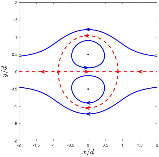
Figure 1.
Phase diagram for a system of two point vortices in the co-moving frame. The vortices (black dots) are located in and , and the circulations are such that . The red dots identify the stagnation points of the system. The red dashed lines correspond to special particle trajectories that constitute a boundary between regions of the infinite plane where particles present different types of trajectories (exemplified in blue lines).
The boundary between the different regions can be defined implicitly using the modified stream function as , or, more explicitly,
The two closed regions defined by Equation (13) are called the atmospheres of the vortices, and their existence has been shown in simulations in numerous works [12,17] for systems of any number of vortices.
It is also possible to obtain an expression for the area of each of these closed regions. Notice that the x- and y-axis are also symmetry axes for the solutions of the system. Thus, we only need to calculate the area enclosed in the region of interest that lies on the first quadrant, i.e., the area below the curve,
It is possible to rewrite Equation (13) as
and by finding (numerically) some such that , the area of each atmosphere can be calculated as
and thus, for a system where the vortices are separated by a distance d, the area of each atmosphere is
It is also possible to compute the perimeter of each atmosphere. The length of the curve can be found as
Thus, the perimeter of each atmospheric island is . Notice that in this case, the shape of the islands does not depend on the circulation k. The results are summarized in Table 1.

Table 1.
Summary of stagnation points and geometric characterization of the atmospheric islands for the case .
Lamb [16] and Meleshko et al. [18] have described the region comprising these two islands as approximately an ellipse; however, it is clear that Equation (15) is not the equation for an ellipse. We can find numerically the points such that and such that on the curve. These points can then be identified as the semi-axes of the ellipse that approximates the vortex atmospheres.
We find and , which makes the elliptical approximation for each island have an area of ≈1.41969734979125 . This corresponds to a relative error of ≈3.76‰ for the area (so, the actual atmospheres have an area slightly bigger than the approximating ellipse). The values we found for , and the area of the approximating ellipse are in line with the findings of [16,18] after adjusting for the difference in the initial distance of the vortices in each study.
2.2. Case
We now consider the scenario where the sum of the non-zero circulations of the two vortices is not equal to zero. It is known that in such a system, the vortices will rotate around their center of vorticity, which can be defined by
with a velocity
where [14,19,20].
Defining the parameter (note that ), the equations of motion of the two vortices can be written as
Notice that having corresponds to , which means that one of the point vortices would have zero circulation, and thus the system would actually be composed of a single point vortex: the vortex would stay in its initial position and give rise to a velocity field that is proportional to the inverse of the distance to the vortex. The case is equivalent, as it corresponds to having instead. The equation of motion for a passive particle in this system is thus
Note that the parameter determines the nature of the system. If , both vortices will have circulations with the same sign. However, if , the vortices will have circulations of opposite signs (though not symmetrically).
Consider the change of coordinates . This corresponds to changing a frame that is rigidly rotating with the vortices around the center of vorticity of the system—located in the origin—at the constant velocity . Thus, in this rotating frame, the vortices have stationary trajectories and . Furthermore, since , we obtain an autonomous equation of motion for a passive particle in this frame:
While not as trivial as in the previous case, finding analytical expressions for the stagnation points of this system is still possible. These points should satisfy
Using and writing a system of equations that both the real and imaginary parts of z must satisfy, we obtain
From the second equation, if , we obtain and, using this in the first equation, we can conclude that
Therefore, there are two stagnation points here, defined by the following:
In the case where y is equal to zero, we obtain a third-order equation for x:
which has either one or three real roots [21], depending on if the sign of the discriminant is negative or positive.
Since ,, we cannot have —which would mean that (27) has a repeated root—since that would only happen if is 0 or 1. We thus conclude that
Thus, if , there are three stagnation points along the real axis, which can be expressed in trigonometric form as
for
If , the sole stagnation point along the real axis can be written as
As such, in addition to the previously defined and , if we have the stagnation points
and, if , we only have
as an additional stagnation point.
In order to obtain more information about the stability of each of the stagnation points and the non-stationary orbits of the system, we need to analyze the equations of motion. Writing them as a system of two real ODEs, we obtain
where we have rescaled time as for simplicity.
The linearization of the flow F defined by the previous equations is thus
where, from now on, and .
For the points and we have
So the eigenvalues of in these stagnation points must satisfy
and, thus, . Therefore, if , then and the stagnation points are both centers; if , then , which means that the stagnation points are both unstable saddle points.
For the points , and , which are of the form , we have
where . So, the eigenvalues of in these stagnation points must satisfy
and, thus, .
Theorem 1.
is negative if and positive if .
Proof.
Using the the fact that on the stagnation points and their analytical expressions, it is possible to infer the signs of and for every . We can write
Since on the stagnation points, we have
Using this on the expression for , we can write
Case :
Since and are both positive, from Equation (38) we see that is a sum of three positive quantities, and thus it is positive. From Equation (40), we see that the sign of is the same as the sign of . Using Equation (30), we can write
Thus,
- Case :
Thus, if , the three stagnation points in the real axis are unstable saddle points, and, if , the single stagnation point in the real axis is a center. The information about the stagnation points in both scenarios is summarized in Table 2.

Table 2.
Stagnation points for the system depending on the parameter .
Once again, it is possible to write a time-independent stream function for this system:
The trajectories of passive particles are thus the level sets of this stream function, or, equivalently, the level sets of
which, for the symmetric case , can be thought of as Cassini ovals [22] that have been deformed by the rotational movement of the system: the curves are compressed along the y-axis and elongated along the x-axis due to the presence of the exponential term in .
Using the stream function and the information on the stagnation points, it is possible to draw the phase diagram of this system for any . We see once again that there exists an atmosphere around each vortex. The boundary of these regions can be characterized as a part of the curve that is implicitly defined by in the case, or in the case. In fact, the curves resulting from these equations separate the 2D plane in various regions. Typically, two passive particles inside of the same region will have similar trajectories, while two particles that are located in two different regions will have distinct trajectories. For instance, particles inside the atmosphere of one vortex will rotate around that region’s vortex; particles that are far away from the vortices will have trajectories similar to the trajectory of a particle rotating around a single vortex in the vorticity center of the system, while other passive particles can have more complex trajectories where they orbit both vortices or none of them. As examples, we plot the phase diagrams for in Figure 2, in Figure 3 and in Figure 4. Notice that there exists a significant distinction in the dynamics of the system depending on the value of and that the case shows some dynamical similarities to the case . In fact, the case is obtained when . The transitions at and are bifurcations where two stagnation points on the x-axis collide with one another and the system goes from five to three (or vice versa) stagnation points. Notice that in these bifurcations, the stability of the stagnation points also changes (see Table 2).
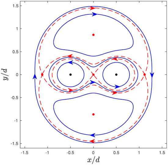
Figure 2.
Phase diagram for a system of two point vortices in the co-moving frame. The vortices (black dots) are located at and , and the circulations are such that and . The red dots identify the stagnation points of the system. The red dashed lines correspond to special particle trajectories that constitute a boundary between regions of the infinite plane where particles present different types of trajectories (exemplified in blue lines).
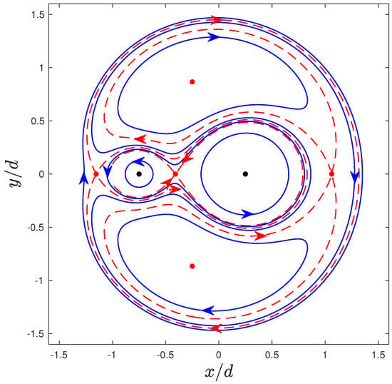
Figure 3.
Phase diagram for a system of two point vortices in the co-moving frame. The vortices (black dots) are located at and , and the circulations are such that and . The red dashed lines correspond to special particle trajectories that constitute a boundary between regions of the infinite plane where particles present different types of trajectories (exemplified in blue lines). The red dots identify the stagnation points.
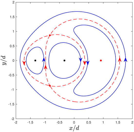
Figure 4.
Phase diagram for a system of two point vortices in the co-moving frame. The vortices (black dots) are located at and , and the circulations are such that and . The red dashed lines correspond to special particle trajectories that constitute a boundary between regions of the infinite plane where particles present different types of trajectories (exemplified in blue lines). The red dots identify the stagnation points.
Due to the complexity of the expression for the stream function and its dependence on the parameter , it is not possible to obtain an explicit expression for the area or perimeter of the vortex atmospheres in this case. However, using (47) it is possible to compute them numerically, and the results are shown in Figure 5, where we plot these quantities for each of the atmospheres as well as their sum for different values of .
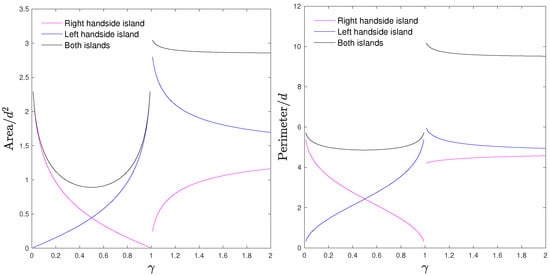
Figure 5.
Area and perimeter of the atmospheric islands around the vortices for .
3. Conclusions and Future Work
Inspired by studies that have shown the existence of stability islands around point vortices in 2D flows, we study and characterize the geometry of the analogous regions for systems of two point vortices (vortex atmospheres). Passive particles in a flow cannot cross the boundary of these regions, and on the inside of the atmosphere, particles are mainly advected by the vortex on the inside of that atmosphere, having a regular trajectory.
In the scenario where the total circulation of the system is zero (), the dynamics can be completely characterized without any parameter dependence. In the frame that is co-moving with the vortices, passive particles on the outside of the atmosphere will eventually move away from the vortices and never approach them again. Passive particles on the inside of the atmosphere of each vortex will describe closed trajectories around them indefinitely. Due to the symmetries in the system, the corresponding regions for each vortex have the same perimeter and area, which can be calculated with arbitrary precision. We found that each atmospheric island has a perimeter and an area (d is the distance between the vortices). The set of both atmospheric islands in this scenario differ from an ellipse by ≈3.76‰ in area.
If the total circulation is not zero, however, the dynamics are completely characterized by a parameter . If , in the frame that is co-moving with the vortices, passive particles can have a multitude of trajectories: if they are on the inside of an atmosphere, they will describe closed trajectories inside the region formed by the associated vortex; in a certain vicinity of the vortices, particles may orbit both vortices in closed loops or describe closed trajectories without orbiting any of the vortices; and if a particle is sufficiently far away from the vortices, it will describe a closed trajectory around both of the vortices. The area and perimeter of the vortex atmospheres cannot be computed analytically due to the complexity of the mathematical expressions involved, but numerical computations clearly show that these quantities scale with the strength of the vortex located on the inside of the region.
If , in the frame that is co-moving with the vortices, particles describe closed, regular trajectories on the inside of the vortex atmospheres once again. There is a third closed region in the 2D plane where particles describe closed trajectories without orbiting any of the vortices, while on the rest of the 2D plane, every particle will orbit both vortices in a closed trajectory. Analytical computation of the area and perimeter of these regions is once again impossible due to the complexity of the mathematical expressions, but numerical computations show that as (equivalently ), the values for these quantities approach the values obtained in the analysis, as one would expect.
We plan to further research in this area, tackling the problem for a configuration of three point vortices. This problem is more challenging due to the fact that we are now dealing with three different circulations.
Author Contributions
Conceptualization, G.M. and S.G.; methodology, G.M. and S.G.; software, G.M.; validation, G.M.; formal analysis, G.M.; writing—original draft preparation, G.M.; writing—review and editing, G.M. and S.G.; visualization, G.M.; supervision, S.G.; project administration, S.G.; funding acquisition, G.M. and S.G. All authors have read and agreed to the published version of the manuscript.
Funding
This research was funded by the CMUP project UIDB/00144/2020. GM gratefully acknowledges support from the FCT grant PD/BD/150537/2019.
Data Availability Statement
No new data were created or analyzed in this study. Data sharing is not applicable to this article.
Acknowledgments
This work honors the memory of Fernando Lobo Pereira, a world-renowned Portuguese expert in Optimal Control, who left us in June 2022.
Conflicts of Interest
The authors declare no conflicts of interest.
References
- Helmholtz, H. Über Integrale der hydrodynamischen Gleichungen, welche den Wirbelbewegungen entsprechen. J. Reine Angew. Math. 1858, 55, 25–55. [Google Scholar] [CrossRef]
- Thomson (Lord Kelvin), W. On vortex motion. Trans. R. Soc. Edinb. 1869, 25, 217–260. [Google Scholar]
- Kirchhoff, G.R. Vorlesungenbër mathematische Physik. Mechanik 1876. [Google Scholar]
- Umeki, M. Clustering Analysis of Periodic Point Vortices with the L Function. J. Phys. Soc. Jpn. 2006, 76, 043401. [Google Scholar] [CrossRef]
- Stremler, M.A. On relative equilibria and integrable dynamics of point vortices in periodic domains. Theor. Comput. Fluid Dyn. 2010, 24, 25–37. [Google Scholar] [CrossRef]
- Crowdy, D. Point vortex motion on the surface of a sphere with impenetrable boundaries. Phys. Fluids 2006, 18, 036602. [Google Scholar] [CrossRef]
- Newton, P.K. The N-vortex problem on a sphere: Geophysical mechanisms that break integrability. Theor. Comput. Fluid Dyn. 2010, 24, 137–149. [Google Scholar] [CrossRef]
- Mokhov, I.I.; Chefranov, S.G.; Chefranov, A.G. Point vortices dynamics on a rotating sphere and modeling of global atmospheric vortices interaction. Phys. Fluids 2020, 32, 106605. [Google Scholar] [CrossRef]
- Nava-Gaxiola, C.; Montaldi, J. Point vortices on the hyperbolic plane. J. Math. Phys. 2014, 55, 102702. [Google Scholar] [CrossRef]
- Ragazzo, C. The motion of a vortex on a closed surface of constant negative curvature. Proc. R. Soc. A Math. Phys. Eng. Sci. 2017, 473, 20170447. [Google Scholar] [CrossRef] [PubMed]
- Aref, H. Point vortex dynamics: A classical mathematics playground. J. Math. Phys. 2007, 48, 065401. [Google Scholar] [CrossRef]
- Babiano, A.; Boffetta, G.; Provenzale, A.; Vulpiani, A. Chaotic advection in point vortex models and two-dimensional turbulence. Phys. Fluids 1994, 6, 2465–2474. [Google Scholar] [CrossRef]
- Neufeld, Z.; Tél, T. The vortex dynamics analogue of the restricted three-body problem: Advection in the field of three identical point vortices. J. Phys. Math. Gen. 1997, 30, 2263. [Google Scholar] [CrossRef]
- Batchelor, G.K. An Introduction to Fluid Dynamics; Cambridge Mathematical Library, Cambridge University Press: Cambridge, UK, 2000. [Google Scholar] [CrossRef]
- Pope, S.B. Turbulent Flows; Cambridge University Press: Cambridge, UK, 2000. [Google Scholar] [CrossRef]
- Lamb, H. Hydrodynamics; Dover Books on Physics, Dover Publications: Mineola, NY, USA, 1945. [Google Scholar]
- Boatto, S.; Pierrehumbert, R.T. Dynamics of a passive tracer in a velocity field of four identical point vortices. J. Fluid Mech. 1999, 394, 137–174. [Google Scholar] [CrossRef]
- Meleshko, V.V.; Konstantinov, M.Y.; Gurzhi, A.A.; Konovaljuk, T.P. Advection of a vortex pair atmosphere in a velocity field of point vortices. Phys. Fluids A Fluid Dyn. 1992, 4, 2779–2797. [Google Scholar] [CrossRef]
- Newton, P. The N-Vortex Problem: Analytical Techniques; Applied Mathematical Sciences; Springer: New York, NY, USA, 2001. [Google Scholar] [CrossRef]
- Chorin, A. Vorticity and Turbulence; Applied Mathematical Sciences; Springer: New York, NY, USA, 1994. [Google Scholar] [CrossRef]
- Nickalls, R.W.D.; Dye, R.H. The Geometry of the Discriminant of a Polynomial. Math. Gaz. 1996, 80, 279–285. [Google Scholar] [CrossRef]
- Basset, A.B. An Elementary Treatise on Cubic and Quartic Curves; University of Michigan Library: Ann Arbor, MI, USA, 1901. [Google Scholar]
Disclaimer/Publisher’s Note: The statements, opinions and data contained in all publications are solely those of the individual author(s) and contributor(s) and not of MDPI and/or the editor(s). MDPI and/or the editor(s) disclaim responsibility for any injury to people or property resulting from any ideas, methods, instructions or products referred to in the content. |
© 2025 by the authors. Licensee MDPI, Basel, Switzerland. This article is an open access article distributed under the terms and conditions of the Creative Commons Attribution (CC BY) license (https://creativecommons.org/licenses/by/4.0/).