1. Introduction
The use of metals and alloys for the manufacturing of several structural elements in mechanical engineering, aerospace and automotive industries, etc., is caused by their outstanding properties such as high specific stiffness and strength, superior conductivity, lightness, and good corrosion resistance (in particular, aluminum and titanium alloys). In order to reduce the production and machining costs as well as the amount of metal waste, especially in the case of MEMS, complex shaped elements are usually manufactured through metal forming, deep drawing, hot stamping, and superplastic stamping of sheet metal or alloy [
1,
2,
3,
4]. However, these commonly used metal forming methods have a number of disadvantages, including high cost, long tooling times, and high energy consumption [
1,
5,
6]. In addition, if the materials (e.g., titanium alloys) exhibit a high degree of elasticity and strength, additional tuning processes are required to reach the desired shape accuracy [
5,
7,
8].
Laser processing is a non-contact technique of forming and micro-forming structural elements. It has many technological advantages, including design flexibility and the ability to form elements of complex shapes [
1,
4,
5,
9,
10]. Laser forming technology is particularly attractive for the manufacturing of structural members made of metal or alloy sheets without the use of expensive equipment. One of the possible laser forming techniques, usually referred to as laser thermoforming (LTF), is provided by pulsed irradiation of the material surface with a focused or defocused laser beam of various durations to create thermal stresses and residual deformations inside the body to generate bending [
1,
5,
10,
11,
12,
13,
14]. That is, the formation of metal sheet parts is achieved by creating laser-induced thermal residual deformations without the application of tools or external forces.
It should be noted that, in addition to laser thermoforming, there is another option for laser surface treatment of thin-walled parts that allows changing their shapes viz. laser microscale shock hardening (LSH) [
5,
8,
15,
16,
17]. This method uses a high-power laser source to form complex shapes of metal sheets, and, unlike laser thermoforming, it is a purely mechanical method of forming by means of a controlled single or multiple laser shock loading [
1,
5,
8,
16,
17]. LSH is generally regarded as a non-thermal process that induces controlled geometric curvature in addition to the desired material response and creates compressive residual stresses in the target material to improve fatigue life and wear resistance under cyclic loading. Indeed, the compressive residual stresses induced during cold working by LSH are highly desirable for increasing the crack and corrosion resistance of structural elements [
8,
15,
16,
17].
Both LTF and LSH technologies have been actively researched and further developed in recent years [
1,
2,
4,
5]. For instance, researchers [
8] have demonstrated their suitability for bending thin strips made of stainless steel with different impact positions and pulse energies. In another work [
11], it was experimentally observed that an aluminum alloy sheet can be processed to provide a different bending direction, which continuously and smoothly changes from concave to convex, i.e., the curvature undergoes a sign shift when the sheet thickness increases or the laser intensity decreases. In another work [
15], a numerical model was proposed to predict the residual stresses induced in a Ti6Al4V hip prosthesis, and in other works [
13,
16,
18], the effect of laser hardening was investigated to improve the resistance of this material to fatigue fracture. In addition, since LTF is a thermomechanical process, materials that are traditionally difficult to form in a purely mechanical way (e.g., titanium, titanium, or nickel-based superalloys) can be easily formed using LTF.
For a more detailed overview of the problem with numerous examples of specific technological applications, see a recent review [
6]. It contains the most remarkable and recent developments in laser-forming technology and applications involving single-layer, multilayer, and composite sheets. In particular, the following important aspects of the technology to be addressed are mentioned there: laser bending of monolithic sheets, laser bending of bi-layer and tailored blanks, laser forming of composite sheets, force-assisted laser bending, laser tube bending, technological parameters optimization, and doubly curved parts are among them.
A short pulse laser beam can be employed to fabricate micro-sized parts like MEMS parts [
6]. Indeed, the use of LTF and LSH looks especially promising in the production of MEMS, where stringent requirements for the production technology dictate high positioning accuracy and high reproducibility combined with low production costs. Thus, the precise positioning of the smallest components is a modern key task in micro-manufacturing. Consequently, laser technology proves to be more time- and cost-effective than traditional approaches, where components are assembled with tight tolerances in the first stage and precise micro-adjustments are made in the second.
However, it should be noted that there are disadvantages to laser thermoforming and laser shock hardening, such as changes (sometimes significant) in the material properties of formed metal parts in the areas of irradiation and pulse exposure, particularly due to intense deformation or thermal effects that lead to undesirable effects of induced anisotropy, changes in microstructure, including recrystallization and phase transformations, possible melting of the structural material during the process, etc.
The effects of pulse temperature loading on material properties and structural behavior are often studied experimentally [
1,
5,
8,
9,
10,
11]. However, to develop specific technological applications and to simulate complex coupled thermomechanical processes, it is necessary to use adequate theories of the thermo-elastic–viscoplastic response of the structural material under laser thermoforming conditions. Numerical modeling of processes, taking account of all the features of the dynamically coupled physically nonlinear behavior of materials, namely inelastic deformation, dynamic changes, thermal recovery, and dependence of material properties on temperature, allows us to analyze both general and specific features of the interaction of mechanical and thermal fields for a wide range of the problem parameters [
18,
19,
20].
The importance of the analytical and numerical simulation of the laser thermoforming process was mentioned in [
4,
6,
10,
21] as well. The first pure analytical approach can be likely attributed to the paper [
22]. Combined analytical and numerical methods were proved to be effective for the estimation of bending angle [
6], for instance. However, the elaboration of an adequate model for the coupled thermo-elastic–viscoplastic response of the material under LTF technology continues to be an issue.
This paper addresses the problem of development and correct application of the thermomechanical problem statement capable of LTF process simulation. The novelty of the proposed approach is that the interaction between a thermal pulse and a structural element is studied, making use of a dynamic problem statement involving a generalized model of the physically nonlinear behavior of materials in a wide temperature range consistent with the thermodynamics of irreversible processes [
23,
24,
25]. Within the framework of the developed new formulation of the problem, the process of laser thermoforming (LTF) is simulated and the effect of a thermal pulse applied in the center of a metal disk is studied [
26,
27]. The problem is solved in an axisymmetric formulation using a finite element methodology developed for modeling the coupled thermomechanical behavior of physically nonlinear materials [
26,
27]. The unsteady process of forming a deflected disk configuration as a result of the residual stress–strain state caused by thermal deformations arising during the rapid heating of the material under the laser spot and the subsequent gradual cooling of the body is studied in detail.
2. Problem Statement
The formulation of the problem of irradiation of a metal structural element by a short-term thermal pulse based on a coupled model of thermos-inelastic behavior was discussed in the literature [
26,
27]. In this paper, the axisymmetric version of the problem statement is used. Below, the equations of the thermo-viscoplastic model of material behavior along with the problem equations are briefly presented. Then the formulation of the initial and boundary conditions usually used in modeling the LTF process are also listed to complete the problem statement.
Let a metal disk (cylinder of small thickness-to-radius ratio) of radius and thickness be considered. Its geometry in the cylindrical coordinate system is given as follows: , .
The formulation of the dynamic axisymmetric coupled problem of thermo-viscoplasticity consists of the equations of kinematics (for small deflections) and dynamic equilibrium/motion in terms of the Cauchy stress tensor as follows:
Kinematic relations:
and equations of motion:
the energy balance equation, which is reduced to the heat conduction equation, is:
mechanical boundary conditions are:
thermal boundary conditions are:
and initial conditions are:
where
,
are the displacements along the corresponding axes;
,
,
, and
are the components of the strain tensor;
,
,
, and
are the components of the stress tensor;
is temperature;
,
, and
are coefficients of linear thermal expansion, heat capacity at constant volume, and thermal conductivity, respectively;
is the volume modulus of the material;
is the power of the given internal heat sources;
is mechanical energy dissipation rate;
is the initial temperature;
’s are the components of the outward unit normal vector to the corresponding boundary surface;
is part of the surface (
,
) subjected to the thermal pulse; and
is the rate of the dilatation. The following differential operator is defined as:
.
To describe the physically nonlinear thermo-viscoplastic behavior of the disk material, a generalized model [
23,
26,
28] is used. It is consistent with the thermodynamics of irreversible processes and consists of
- -
representation of the total strain as a sum of elastic, inelastic, and thermal components
- -
Hooke’s law written for the deviatoric and volumetric parts of the stress tensor
- -
the flow rule accompanied by the condition of plastic incompressibility
- -
kinetic equation
- -
and the evolution equations for the internal variables of isotropic and kinematic hardening
The values
,
,
,
,
,
and
are constants of the constitutive model. Experimental and theoretical studies [
23,
24,
27] have shown that for most metals, the parameters
,
, and
demonstrate weak dependence on temperature and can be considered constant over a wide temperature range meanwhile the parameters
,
,
, and
are functions of temperature.
Since the processes studied in this paper are quite fast, the phenomenon of thermal recovery can be neglected when describing the behavior of the material. Therefore, the terms describing this phenomenon are omitted in Equation (13).
The model of material response with internal state variables requires an appropriately modified expression for the dissipative function
. The expression for the model used was derived in [
27] in the frame of thermodynamics of irreversible processes. Thus, the mechanical energy dissipation rate in Equation (3) is of the following form:
The values of
and
are internal variables conjugate to the thermodynamic forces
and
(parameters of isotropic and kinematic hardening, respectively) [
26,
27].
We assume that a laser pulse irradiates the center of the surface
over a circular spot of radius
. This single thermal pulse is modeled by a specified heat flux
of duration
across the disk boundary. The time–space law describing the pulse is given as follows:
A thermal insulation condition is assumed on the rest of the disk surface. After the pulse has ceased, the irradiated part of the surface is also considered to be thermally insulated.
Equations (1)–(13) with initial and boundary conditions and Equation (14) constitute the formulation of a coupled problem of thermomechanics of physically nonlinear solids under thermal loading.
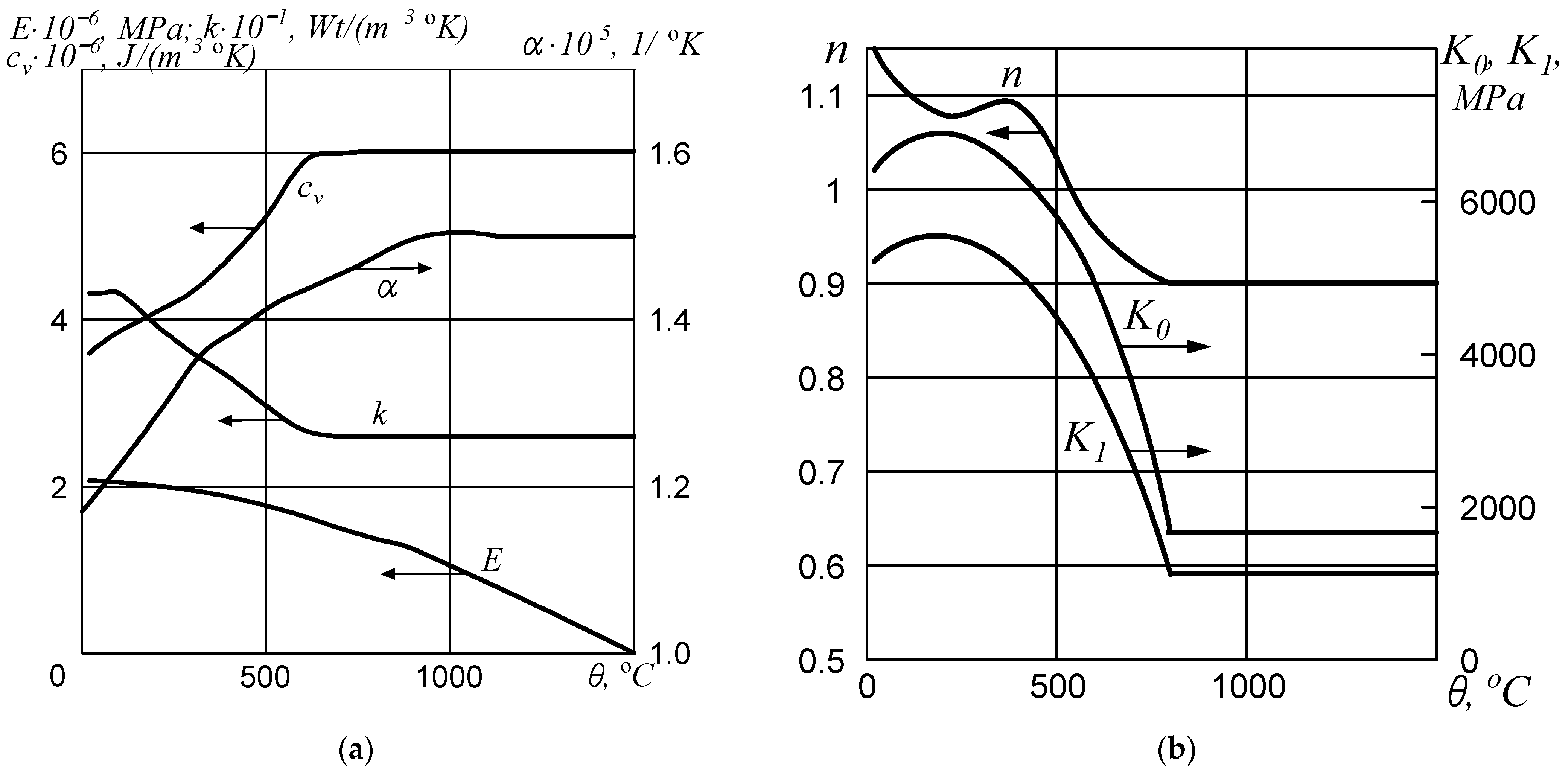
3. Material Properties
Steel 35CrMo was chosen as the disk material. The physical and mechanical properties of this material and their dependencies on temperature were taken from [
24,
26,
27] and are shown in
Figure 1a,b.
For the selected material, in the studied range of strain rates and temperatures, the parameter turned out to be practically independent of temperature and equal to 0.03 MPa−1.
Since the model is phenomenological in nature and quite complex, the methodology for determining its parameters, even for the isothermal case, is rather complicated. The procedure is described in detail, particularly in [
23,
24,
28]. It requires the processing of a series of diagrams for monotonic tensile tests for specimens under different strain rates. It appeared to be possible to determine all the necessary parameters of the Bodner–Partom model [
23] even for the cases of alternating or cyclic loading. To obtain temperature dependencies, this procedure has to be repeated for sets of diagrams corresponding to different temperatures.
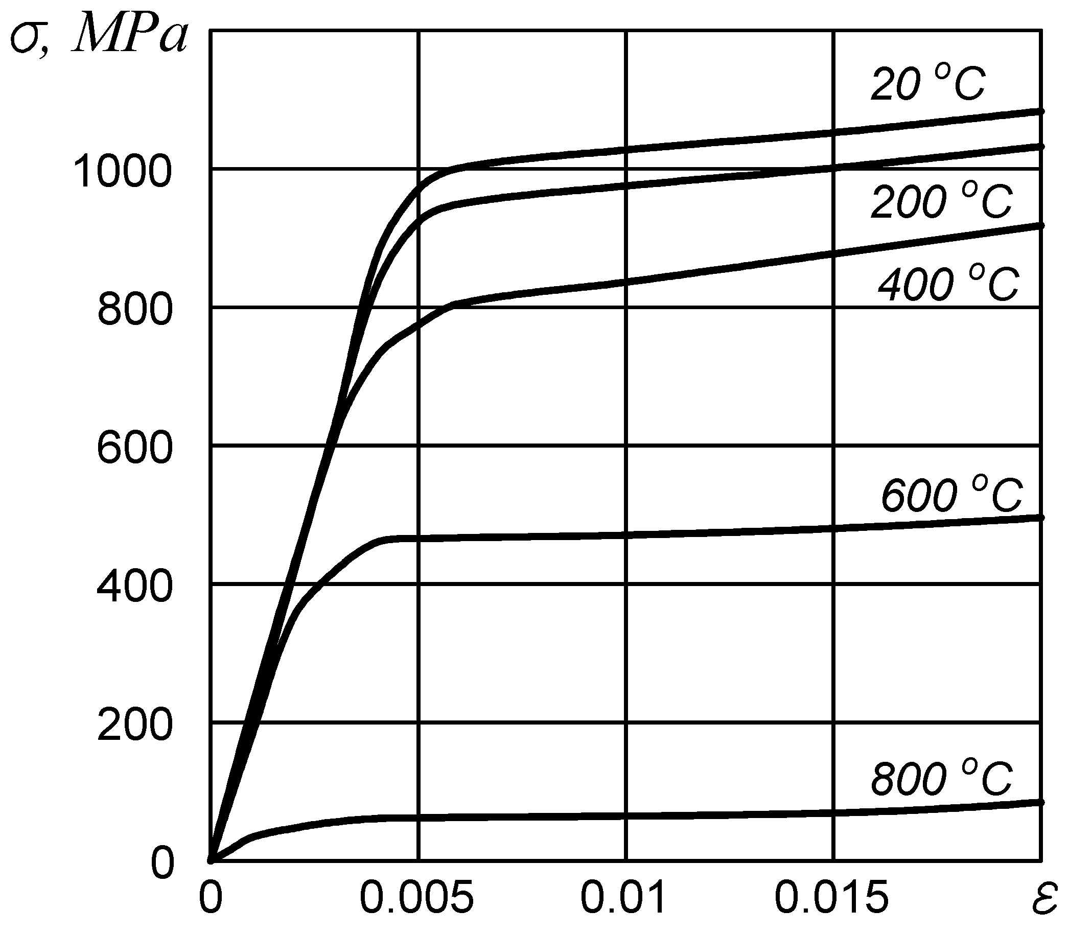
In this paper, experimental data from the literature [
24,
28] were used to determine all the necessary model parameters and their temperature dependencies. In particular,
Figure 2 shows the diagrams for 35CrMo steel at different temperatures for the strain rate 5·10
−4 c
−1. In the calculations, diagrams of monotonic tensile tests were used with the strain rates 0.3, 91.25, and 4·10
−4 s
−1. The diagram for the latter was calculated using numerical modeling based on the uniaxial monotonic tensile problem for the limiting values of the Bodner–Partom model parameters corresponding to the specified temperature. The experiments available in the literature were conducted only in the temperature range of 20–800 °C [
23,
24] and the results for higher temperature values are not available. Therefore, in this temperature range, the values of the required parameters were assumed to be equal to those corresponding to the temperature of 800 °C.
4. Solution Technique
The problem statement as formulated by Equations (1)–(14) represents an essentially nonlinear problem that may only be solved numerically. Here, the same approach as developed in [
26,
27] for solving dynamic plane and axisymmetric problems of hermos-viscoplasticity is adopted.
The numerical implementation of this technique is carried out as a double iterative process. The first process (internal) is associated with the integration of the system of nonlinear equations of the material response using an implicit integration scheme. The second process (external) deals with the solution of the equations of motion and heat conduction. It takes into account the temperature dependence of the material properties and the parameters of the Bodner–Partom model. The presence of regions of rapid solution change during the transition from elastic to plastic deformation requires the use of schemes with variable time increments. The evolution equations are integrated by the implicit Euler method using the central-difference scheme. The system of nonlinear transcendental equations that arises at each time step is solved by a simple iterative method. The Steffensen–Aitken procedure is used to improve the convergence rate.
The spatial discretization of the problem is carried out by making use of the finite element method (FEM). The calculations were performed for a fine mesh, especially in the irradiated area, to correctly simulate the thermomechanical response caused by large temperature gradients. The mesh parameters were chosen by means of a practical criterion for the convergence of solutions.
The application of FEM within the framework of the external iterative process leads to the problem of the dynamics of viscoelastic solids in the following form:
where
and
are the stiffness and mass matrices, and
,
,
,
, and
are the vectors of nodal displacements, nodal velocities, external forces, initial displacements, and initial velocities, respectively.
The second time derivatives in the equations of motion for a moment of time
are represented by Newmark’s formulas as follows:
where
is a time step and
is the scheme parameter,
.
Substituting Equation (16) into Equation (15) after transformations yields:
For the special case of
, from the relations between Equations (16) and (17), one can derive a recurrent system of linear algebraic equations to find the solution at the
-
th increment:
where
,
.
In the proposed scheme, the terms and take account for thermal and plastic strain, respectively.
At each time increment, the problem is solved by the iteration method as well. Each iteration consists of solving a linearized problem of motion of the following form:
where
is the iteration number.
5. Calculation Results and Analysis
Calculations were performed for a disk of radius m and thickness m, which are typical for micromechanical systems. The radius of the irradiation zone was m, the pulse durations have been varied from s to s, and the heat flux parameter was also varied from to kW/m2. The initial temperature of the disk was assumed to be at room temperature of 20 °C.
The mechanism of laser thermoforming of thin-walled parts is to create laser-induced thermal residual strain without the use of tools or external forces. As a result, the modeling of such a process should be carried out within the framework of a non-stationary coupled thermomechanical theory. When a disk is irradiated, a region of high-temperature gradients occurs on the surface and in the near-surface zone, which changes its configuration over time. The modeling of the irradiation process shows that the evolution of temperature distributions along the radius and axis of the disk is characterized by rapid heating of the material to 1300 °C (that is below the melting point) in the near-surface zone. After the end of the laser pulse, in the absence of heat exchange with the environment, the temperature gradually equalizes over the disk volume, which is carried out rather slowly. It should be noted that the temperature effects are strongly localized in a quite narrow lens-shaped region of material in the immediate vicinity of the irradiated spot. During the simulation interval, the temperature does not increase significantly outside the irradiated area.
As a result of the fast expansion of the material over the irradiated zone, significant compressive stresses occur, which form a quasi-static component of the stress field. After a significant time has elapsed compared to the pulse duration (for the considered configuration and conditions, calculations showed that the stabilization time can be chosen as s), the compressive stresses disappear, and a region of quasi-static residual tensile stresses is formed in the center of the disk, which can subsequently compromise the strength and durability of the structure.
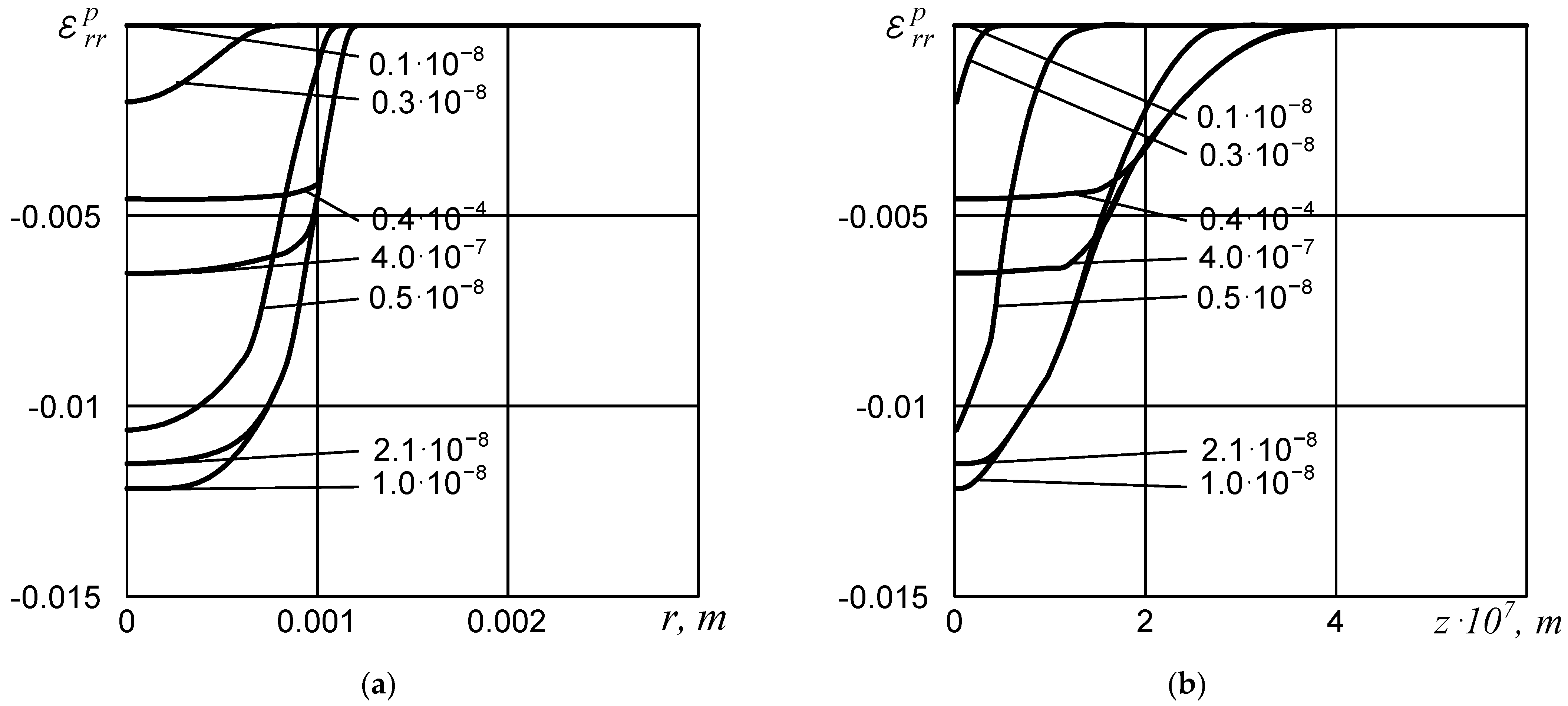
Since the induction of the residual inelastic strain is a key factor in LTF technology, the present investigation is mainly focused on the study of the inelastic strain field and its evolution over time. Simulation of the inelastic strain field behavior has shown that under the considered conditions of pulse laser irradiation, significant inelastic strains are generated in the disk. Evolution of the distributions of radial inelastic strain component
along the radius at
(bottom face of the disk) and along the disk axis are shown in
Figure 3a,b. The data are plotted for the case of the heat flux parameter value of
kW/m
2. The numbers by the lines in the figure correspond to the time moments.
The inelastic deformation starts at s. Inelastic strain components reach their maximum magnitudes at the moment of termination of the pulse action. Further, at the stage of thermoelastic unloading, they remain constant. Subsequent cooling of the disk is accompanied by the appearance of secondary inelastic strains. As a result, the inelastic strains decrease rather slowly. The field of residual inelastic strains is formed approximately by time s. The calculated values are as follows: , . The area of their localization is a circle of radius that equals approximately 1.1 mm. This particular pattern of the residual state is governed by the geometrical, physical, and temporal characteristics of the laser pulse.
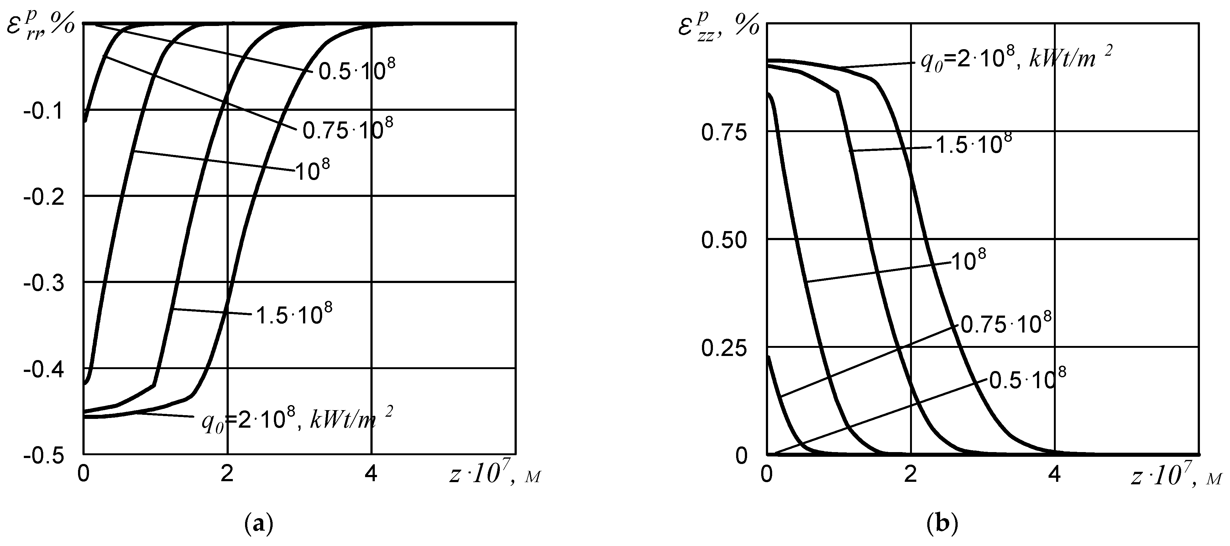
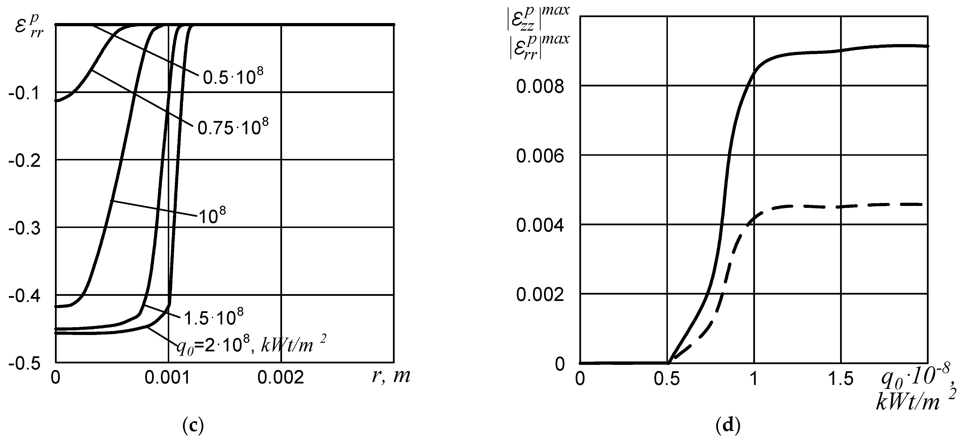
Since the estimation of the residual field of inelastic strain is crucial from the point of view of thermoforming, it was necessary to solve the problem in a nonstationary formulation and to trace the evolution of the components of this tensor over a long time interval for different values of the pulse parameter
.
Figure 4a–c show the results of this study. The distributions of the components
and
of the residual inelastic strain at
as well as
at
are plotted for different values of the heat flux parameter
.
Figure 4d shows the variation of the maximum magnitude of component
with parameter
. A similar dependence for
is shown by the dashed line. It can be seen from the graphs that an increase in heat flux leads to an expansion of the thermal pulse influence region. However, this expansion manifests itself differently along the axis and along the radius of the disk. For a given disk geometry, spatial and temporal distribution of the pulse along the radius, the size of the pulse influence region increases rapidly at the beginning. Then, when approaching the size of the spot radius, the growth slows down significantly and saturation occurs. This behavior is explained by the shape of the pulse along the radial coordinate
. The inelastic strain components saturate along the disk axis, while the size of the region itself continues to grow almost linearly. This is due, first of all, to the narrowness of the pulse influence region along the
axis.
The analysis of
Figure 4 shows that it is useful to determine the size of the thermal pulse influence region, in particular, by the magnitude of the inelastic strain components.
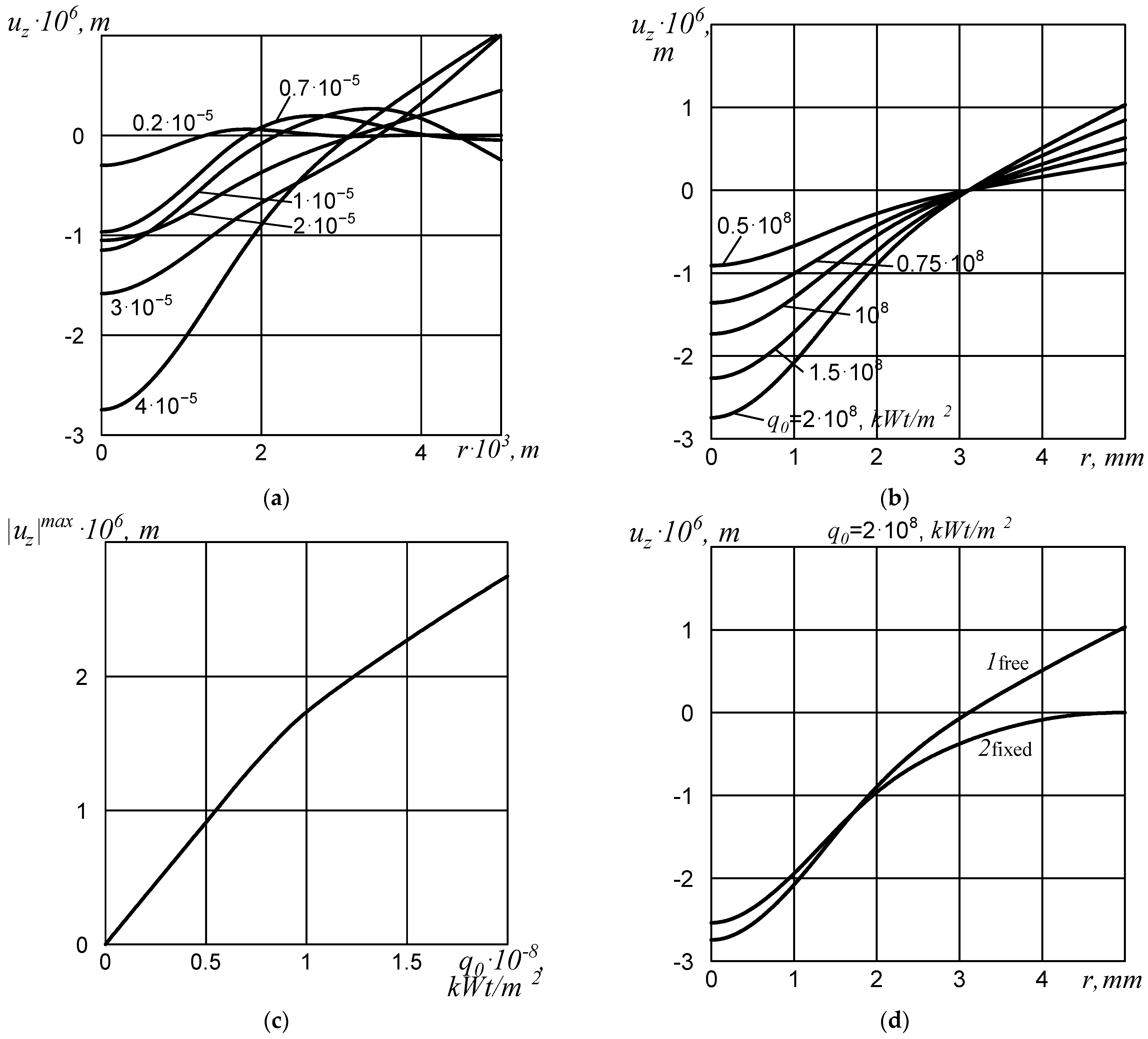
The developed problem statement, the method of its solution, and the obtained modeling results were used to study the applicability of the LTF technology to treat the structural elements by short thermal pulses for the purpose of stamping or forming the desired profile (configuration). The presence of significant inelastic strains induced by thermal processing, which are asymmetric relative to the median surface of the disk, leads to a modification of the surface curvature of metal plates, shells, and structural elements without the use of an external force load. The results of modeling this process are illustrated in
Figure 5.
Figure 5a shows the evolution of displacements of the surface points of a disk irradiated by a laser pulse for the case of a free edge. The time moments for which the surface profiles were drawn are marked with numbers. The maximum deflections are achieved in the center of the disk.
Figure 5b shows the residual displacements of the disk surface under the influence of pulses of different power. For higher laser pulse powers, which are simulated by an increase in the heat flux parameter
, an increase in surface deflections is observed both in the center and at the edge.
The maximum deflection is always observed in the center, with the bend directed toward the irradiated side. The edge of the disk moves in the opposite direction. The dependence of the maximum displacement magnitude on the heat flux parameter is shown in
Figure 5c. It has a bilinear character for the studied region of parameter
. At the value of
kW/m
2, the dependence angle change occurs, therefore the dependence characteristic softens.
An additional factor that affects the quantitative characteristics of the thermoforming is the conditions applied at the disk edge. The results presented in
Figure 5a–c correspond to the free edge.
Figure 5d shows a comparison of the residual displacement profiles of the disk surface calculated for problems with free and fixed disk contours. Curve 1 corresponds to the free edge, while curve 2 complies with the case of the fixed one.
Qualitatively, the behavior of the curves differs only in that the free edge of the disk is raised, i.e., a region of positive displacements is formed over the edge zone, while in the center the displacements are negative. However, in the case of a fixed contour, the residual deflections for the given problem parameters are predicted to be 7.5% smaller than in the case of a free contour.
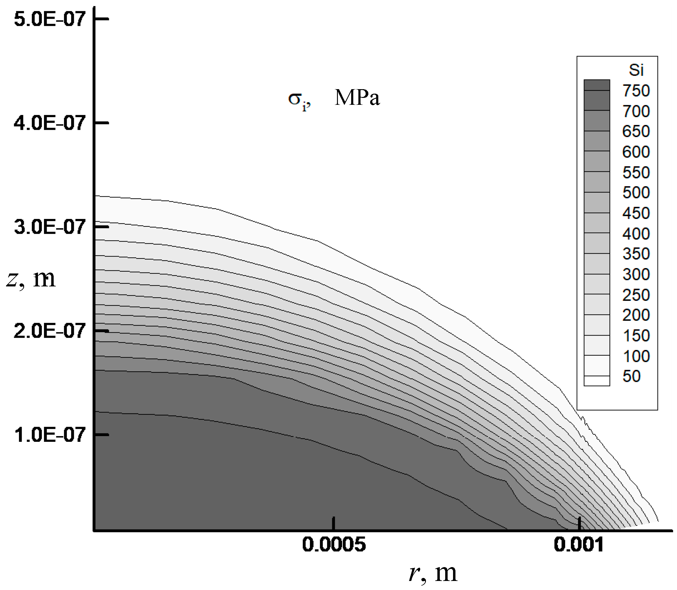
An important issue when using the proposed technique of laser pulse treatment simulation and final shape study is the assessment of the residual strength of a structural element being irradiated. It should be noted that there are many criteria for such an assessment. They are based on the use of maximum principal stresses or strains, maximum tangential stresses, maximum shear strains, octahedral stresses, maximum inelastic strains, stress intensity or plastic strain intensity, etc.
Figure 6 shows the residual stress intensity field in the vicinity of the irradiated zone. The field of inelastic strain intensity and the field of maximum principal stresses show similar behavior. The maximum is observed directly in the center of the disk (irradiation zone). When approaching the edge of the heat spot,
,
and
decrease sharply. The area of dangerous values of the studied values is located inside a circle with a radius of approximately
mm. Outside of it, the levels of residual stress and strain intensities, and maximum principal stresses are insignificant.
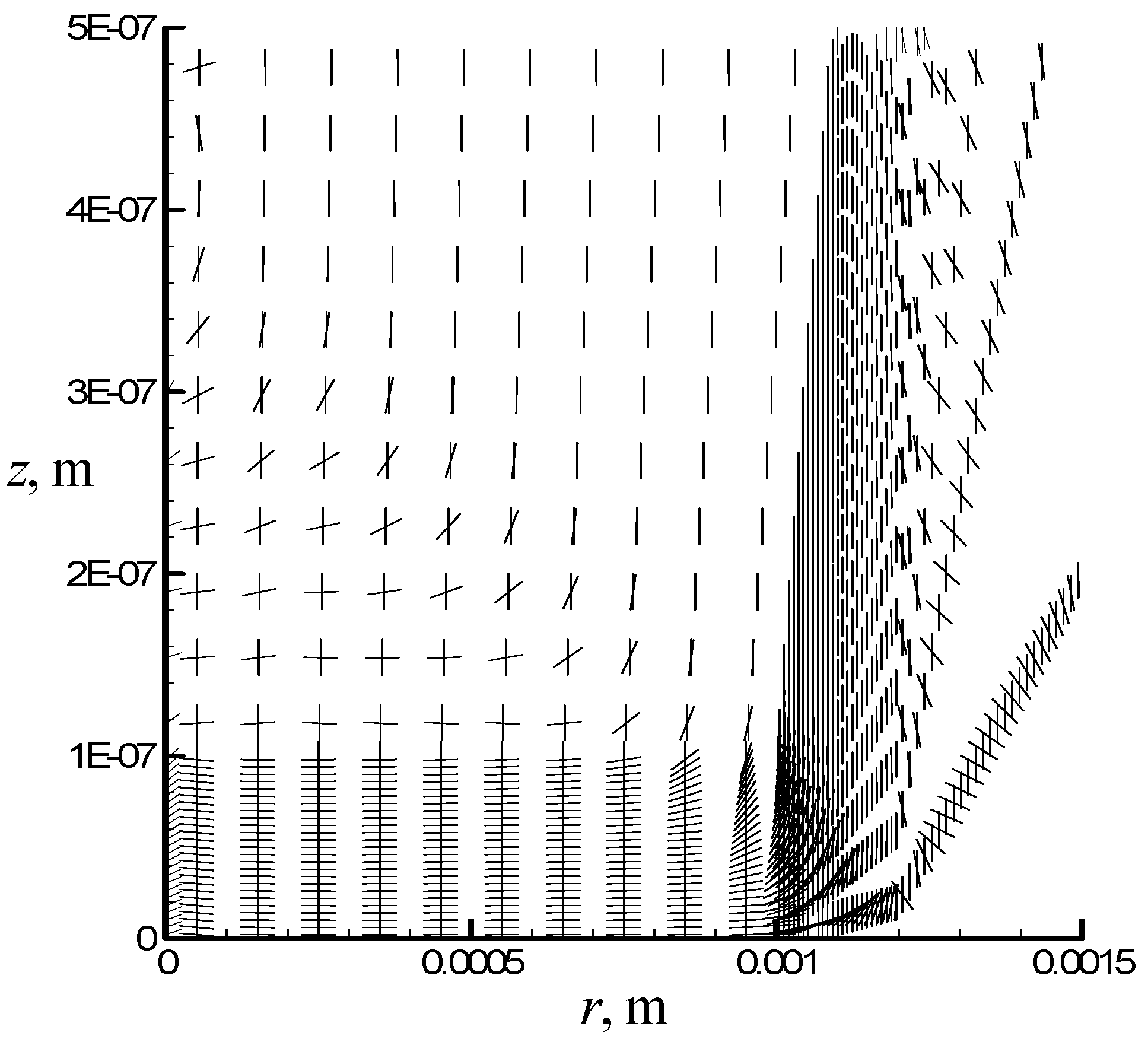
The directions of the maximum principal stresses in the danger zone are shown in
Figure 7.
In general, to assess the residual strength of a structural element of a given shape of the considered geometry treated with short thermal pulses, any of the criteria based on the use of stress intensities, deformation, or maximum principal stresses, as well as criteria combining these values, can be applied.


