Abstract
Free Route Airspace (FRA), a new concept implemented across European airspace, is designed to eliminate the adverse effects of air traffic, reduce fuel consumption, simplify and expand flight planning. In our research, we model FRA system by using graph theory and we use networks and convex analysis to study it. We work with 2-dimensional space defined by latitude a longitude. We know that the basic mathematical properties of a scientific discipline can be expressed using mathematical axioms. Therefore, in our work, we sought to answer the question, what are the basic mathematical properties of airspace? We found a mathematical object that can describe airspace in general. Using this object, we uttered an axiom describing airspace. Our axiom is given by means of practical, significant entry and entry-exit points in the airspace.
MSC:
93A05; 51M15
1. Introduction
Free Route Airspace (FRA) is an essential function of Air Traffic Management (ATM). This is a new operational concept developed to modernize airspace. This concept will help reduce ATM costs, the environmental impact of aviation, fuel consumption and emissions, and improve flight efficiency. FRA is a defined area of airspace in which airspace users are free to plan a route using significant FRA points. A more detailed overview of FRA is presented in our article [1]. FRA is a real system currently being used in Europe; the responsible organization for its development and implementation is EUROCONTROL. In our research, we are modelling the FRA system by using the graph theory, networks, and convex analysis.
The application of graph theory in airspace modelling has been already a subject of research from different authors. In the work [2] the authors focused on the FRA overview in comparison to the classical, network-based airways structure and on an airspace model applicable to the automatic route selection process to facilitate the entire flight planning process. Another research on this subject was included in the work [3] where the author described a problem of air routing and discussed the use of algorithms/approaches in the conventional Air Traffic Services (ATS) route network and FRA environment. In work [4], there are several graph-based airspace models, for more efficient free route planning. These graph models use the FRA concept.
Although in our research we work with 2-dimensional spaces defined by latitude and longitude and we do not use the vertical position of an aircraft (or of obstacles), we use the term "airspace" very often. It should be noted that, in general, airspace is defined as a 3-dimensional part of the atmosphere, so this designation of airspace in our manuscript is a limitation and there are intentions to extend it with the other dimensions, i.e., height and time. At the moment, for completeness of the topic and possible further research, we believe that a short description of different ways how to indicate the vertical position in the airspace would be beneficial and could be used in the future.
New technological concepts like FRA are complex matter with extensive documentation. The main goal of our article is to assign a general, basic and simple mathematical axiom to the FRA concept. The axiom describes the fundamental mathematical properties of a given concept and concepts of a similar type. This axiom may serve as a primary interface between the technological concept and mathematics.
Scientific articles contain new research results expressed using mathematical theorems, new methods or algorithms. Axioms are obvious statements that we do not even need to prove, so this work has a different character than the classic scientific article. In such research, it is necessary to find the mathematical object or statement that best characterizes the investigated topic.
2. Coordinate Systems
We will need some basic concepts before we can state our axiom. In this chapter, we will discuss the coordinate system.
We use coordinate systems to determine locations on and around the Earth. The airspace can be represented using Cartesian coordinates in an Earth-centered-Earth-fixed (ECEF) coordinate frames (or Geocentric coordinate system). Cartesian coordinate system use two or three numbers, a coordinate, to identify the location of a point. Each of these numbers indicates the distance between the point and a fixed reference point, called the origin. ECEF origin is at the center of Earth. The origin has coordinates . The distance from the origin is defined for each point . The unit that is used to measure the distance from the origin will be meter (kilometer (km)) or feet. The points of airspace are located in a sphere bar, which can be expressed by inequality
where r is the radius of the globe and R is the highest flight level (see next chapter). The value of R is approximately 100 km, for the purposes of our article. Beyond this distance ( km), the points already belong to the cosmic space.
The surface points of the Earth are not well described by inequality , so we use the projections on the Earth surface. The projection that is used to draw the Earth on a flat map will be expressed by longitude and latitude.
We will use this projection of airspace
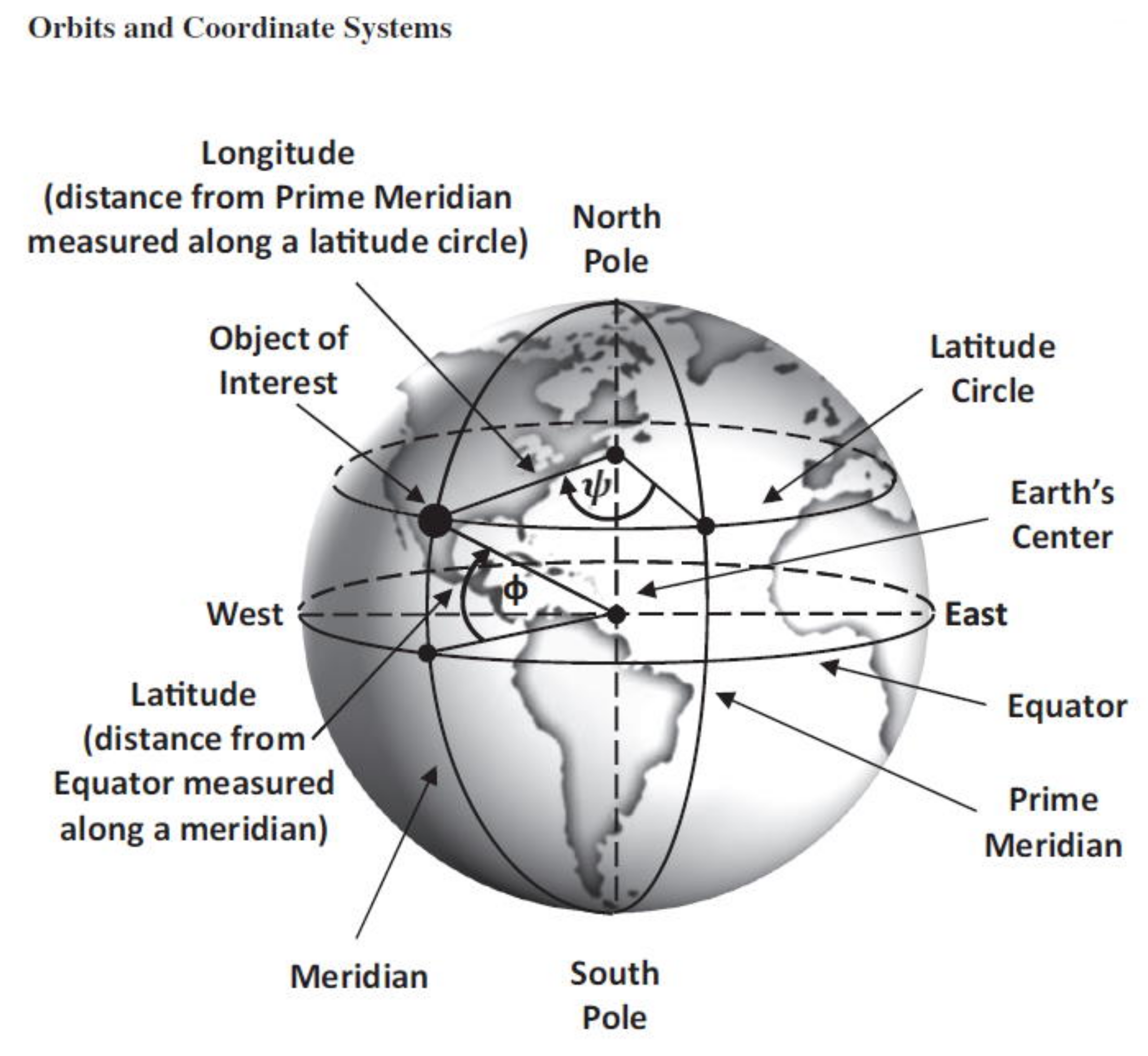
to state our axiom. It is a special kind of coordinate system, called a geodetic coordinate system, since they identify points on Earth’s surface. A more detailed description of the coordinate systems can be found in the books [5,6] and a brief explanation of the issue on the Internet [7]. Figure 1 contains the main elements of the system.
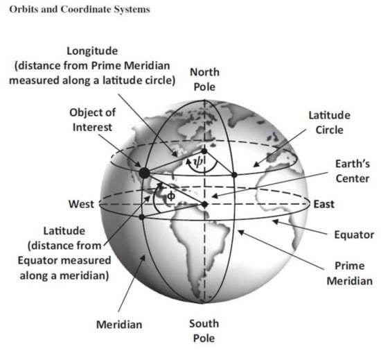
Figure 1.
Geodetic (spherical) coordinate system. Reprinted/adapted with permission from [5], 2019, J.L.Lawrence.
When we also consider the flight altitude, we have a coordinate system with coordinates
There are conversion functions from coordinate system to [longitude, latitude, altitude] and vice versa. The coordinates [longitude, latitude, altitude] are given in degrees, minutes and seconds. A description of these coordinates and transfer functions can be found in [5]. We assume that, each airspace, as a set of points or [longitude, latitude, altitude] is spatially bounded by relation (1).
We will not consider the of the space for our purposes. The point [longitude, latitude] on the projection of the airspace means Global Positioning System (GPS) coordinates for geolocation of a point (for description of GPS system see [8]). Thus given airspace points with coordinates are called significant points. We examine what types of airspace areas are covered by these points and what mathematical properties these areas have.
3. Vertical Positions and Other Limitations
We only work in 2-dimensional spaces, which is given by [longitude, latitude]. The vertical position of an aircraft (or of obstacles) is not used when specifying axioms. The distance between two points is calculated based on a line, not a circular arc.
However, for completeness of the topic and possible further research, in this chapter, we will shortly describe different ways of indicating the vertical position in the airspace with which we could work in future.
In general, any 3-dimensional part of the atmosphere can be called airspace. However, from a legal perspective, airspace extends from the surface of the earth and through coastal waters to an unspecified height while it is bounded by the national border of the State.
In terms of airspace management and the range of navigation services provided, the airspace can be divided into two basic categories:
- 1.
- Controlled airspace: this area extends to flight level 660, or 66,000 feet.
- 2.
- Uncontrolled airspace: an area in which any flight activity is subject to basic rules and regulations without the issuance of air traffic control instructions, see [9].
Vertical positions are expressed in feet (ft); they can be expressed in meters (m) and the ways of how to indicate these positions are the following:
- 1.
- Height/absolute altitude is defined as a vertical distance of an aircraft above whatever surface the aircraft is flying over, e.g., building, crane, sea, etc. In other words, height refers to the distance between an aircraft and the ground. Height is expressed in feet AGL (Above Ground Level) or meters in some countries.
- 2.
- Indicated Altitude (ALT) is defined as a vertical distance of an aircraft above the mean sea level (MSL). Altitude is expressed in feet AMSL (Above Mean Sea Level) or meters in some countries.
- 3.
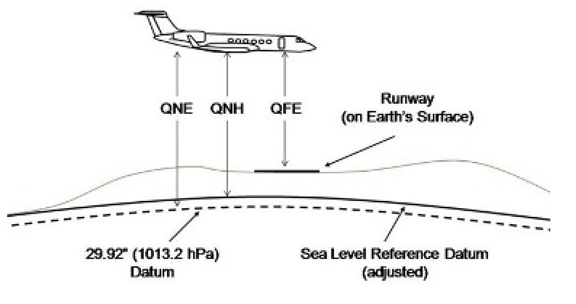
- Flight Level (FL)/Pressure Altitude is an indication of pressure, not of altitude. FL is used to ensure safe vertical separation between aircraft. It is defined as a vertical distance of an aircraft above the isobaric surface (an isobaric surface is an invisible landscape that connects all points with the same atmospheric pressure.) of 1013.25 hPa (hecto Pascal) or 29.92 in Hg (inches of Mercury) and is separated from other such surfaces by specific pressure intervals. It is also known as QNE. In aviation, 1013.25 hPa/29.92 in Hg are referred to as the standard altimeter setting. The Flight Level is represented by FL, with the altitude in hundreds of feet (while being a multiple of 500 ft) and so always ending in 0 or 5. FL is followed by three digits, for example, 10,000 feet become Flight Level 100 = FL100; 3500 feet become Flight Level 035 = FL035. FL is an altitude flown on the standard QNH setting of 1013.25 hPa or 29.92 in Hg. By this, it is ensured that each aircraft is flying with reference to the same setting, which implies less chance of flying into each other. The airfields have different QNH (local altimeter settings) values because of differences in locations. Consequently, the 1013.25 hPa isobaric surface is a fictive curve that can be greater/lower than the mean sea level surface.
An important flight instrument necessary for a pilot to maintain the desired or assigned altitude during flight is called Altimeter.
The most common types of altimeters are barometric; they determine the vertical distance of an object (aircraft) above a fixed level by measuring air pressure differences (compare the pressure of outside static air to the standard pressure 1013 hPa of air at sea level).
In relation to this, there are three references in use for barometric pressure:
- -
- QFE (Field Elevation). This refers to a pressure set on the subscale of the altimeter to produce the height above the reference elevation being used. With the aerodrome QFE set in the subscale, the altimeter will read zero when an aircraft is on the runway and will give height above the runway when an aircraft is airborne.
- -
- QNH (Height Above Sea Level). This refers to a pressure set on the subscale of the altimeter to produce the height above sea level. It reads runway elevation when the aircraft is on the runway.
- -
- QNE. This refers to a pressure setting of 29.92 inches or 1013 hPa that will produce a standard atmosphere altitude and provides the basis for flight levels, see [10] and Figure 2.
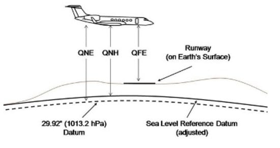 Figure 2. Flight Level.
There are, of course, other types of altimeters that do not depend on the air pressure. For example, the Global Positioning System (GPS) receivers determine altitude by trilateration with four or more satellites. Radar and laser altimeters send a radio or laser signal toward the surface and measure the time it takes for the signal to bounce back. The time it takes for the signal to bounce back to the aircraft is translated to an elevation.
4. Mathematical Model of Free Route Airspace
4.1. Introduction to Free Route Airspace
To model Free Route Airspace (FRA) and to record all these created models and related algorithms, we are using the mathematical graph theory, networks, and technology Cloud Computing. These technologies and theories are essential to document the system, data structure of different objects, data analysis, and specific data of airspace and programs in which the models and algorithms are recorded (see [1] and FRA Research Cloud [11]). FRA is one of the essential Air Traffic Management (ATM) functionalities (ATM—The dynamic, integrated management of air traffic and airspace, including air traffic services, airspace management and air traffic flow management. Source: ICAO Doc 4444 PANS-ATM). For an effective study of this system, in our view, the best way is to do it by mathematical modelling. In our research, the FRA system is represented by a network. In this network, the vertices of the network represent an airspace where the FRA is implemented. The edges of the network present the adjacent airspaces. Each vertex of this network is an FRA airspace. Each FRA airspace is a graph. In this graph, the significant points represent the vertices. We can create the algorithms for calculating the most effective flight, using this graph, see ([11], Algorithms Section). The terms significant points, FRA Graph, FRA Network will be defined in the next chapter.
4.2. Graphs and Networks
In our previous work [12] we defined some basic concepts of graph theory. Now, we recall the relevant terms and notations from this work. Basic concepts of graph theory such as graph, network, vertices, and edges can be found in the publication [13], among many other sources. Network theory is a special part of graph theory. Air route networks and other complex networks are described in work [14].
4.3. Encoding of the GFRA Graph Vertices and Edges
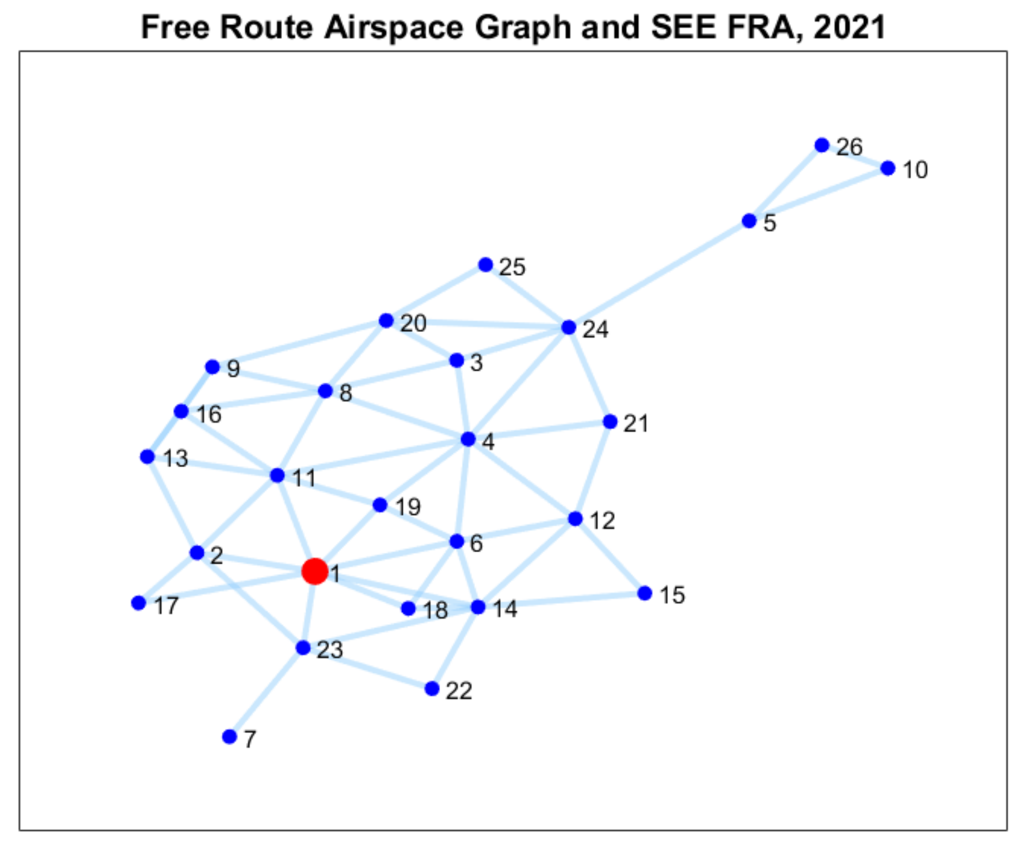
In this chapter, we define a graph for FRA. This graph is labeled as GFRA. By means of the GFRA, we can define a complex network (see FRA Research Cloud [11], Algorithm Section, A[1]—FRA a Complex Network). Let be a graph, where individual FRA areas create the set of vertices V. We see this graph in Figure 3. For better visualization, the vertex (red dot on the picture) displays the SEE FRA (South-East Europe Free Route Airspace in 2021) area consisting of the airspace of Slovakia, Hungary, Romania, and Bulgaria. We can load the adjacency matrix of GFRA from the database (see [11], Data and Data Structure Section—FRA_Matrix.csv). Information on a specific, local implementation of the FRA concept can be found in work [15].
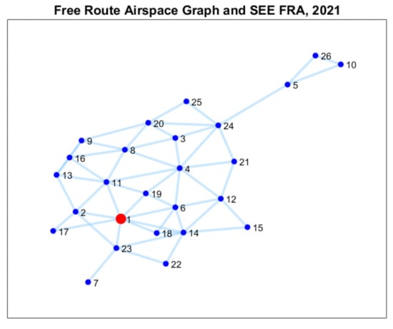
Figure 3.
Graph Free Route Airspace, 2021.
Let E be the set of edges, and if only if the vertices and are adjacent. The vertices are adjacent if there is a transition from to .
4.4. The FRA Significant Points
In the graph GFRA, each vertex is airspace. In this chapter, we will examine the properties of this airspace. We will examine how airspace is defined according to the FRA concept. The airspace is defined by Significant Points. The point is given by GPS coordinates, name, and other attributes. For more details, see ([11], Documentation Section, EUROCONTROL FRA Design Guidelines). The FRA significant points, (see [11], Data Structure Section) are divided in:
- 1.
- FRA Horizontal Entry Point (E)—We define a Boolean function E(P). The function value E(P) is true if and only if P is an Horizontal Entry Point.
- 2.
- FRA Horizontal Exit Point (X)—We define a Boolean function X(P). The function value X(P) is true if and only if P is an Horizontal Exit Point.
- 3.
- Combined FRA Horizontal Entry and Exit Point (EX) - We define a Boolean function EX(P). The function value EX(P) is true if and only if P is an Horizontal Entry and Exit Point.In some exceptional cases, the above-described points can be located inside or outside the relevant FRA (instead of being located at the horizontal border).
- 4.
- FRA Arrival Connecting Point (A).
- 5.
- FRA Departure Connecting Point (D).
- 6.
- Combined FRA Arrival Connecting and FRA Departure Connecting Points (AD)
- 7.
- FRA Intermediate Points (I)—This point is located inside the FRA area.
According to the ICAO Annex 11 Air Traffic Services, a significant point is defined as a specified geographical location used in defining an ATS route or the flight path of an aircraft and for other navigational and ATS purposes. Indeed, a definition of a significant point is the same for ATS network and for FRA. But when we use the terms—FRA horizontal entry/exit significant points, FRA intermediate points, these terms exist only in the FRA context. On the ATS route, we do not use definitions of entry/exit/intermediate points.
In general, by significant points, we can define the geographical area. That is why the principle described in our manuscript is applied not only for FRA but for any other field of operations where geographical areas play an important role. The selection of significant points plays an important role when we want to define an area by using these points. In our manuscript, the significant points are used for FRA purposes. FRA serves as an example for the application of significant points, but they can be, of course, used in any other application.
4.5. NFRA Network and Significant Points
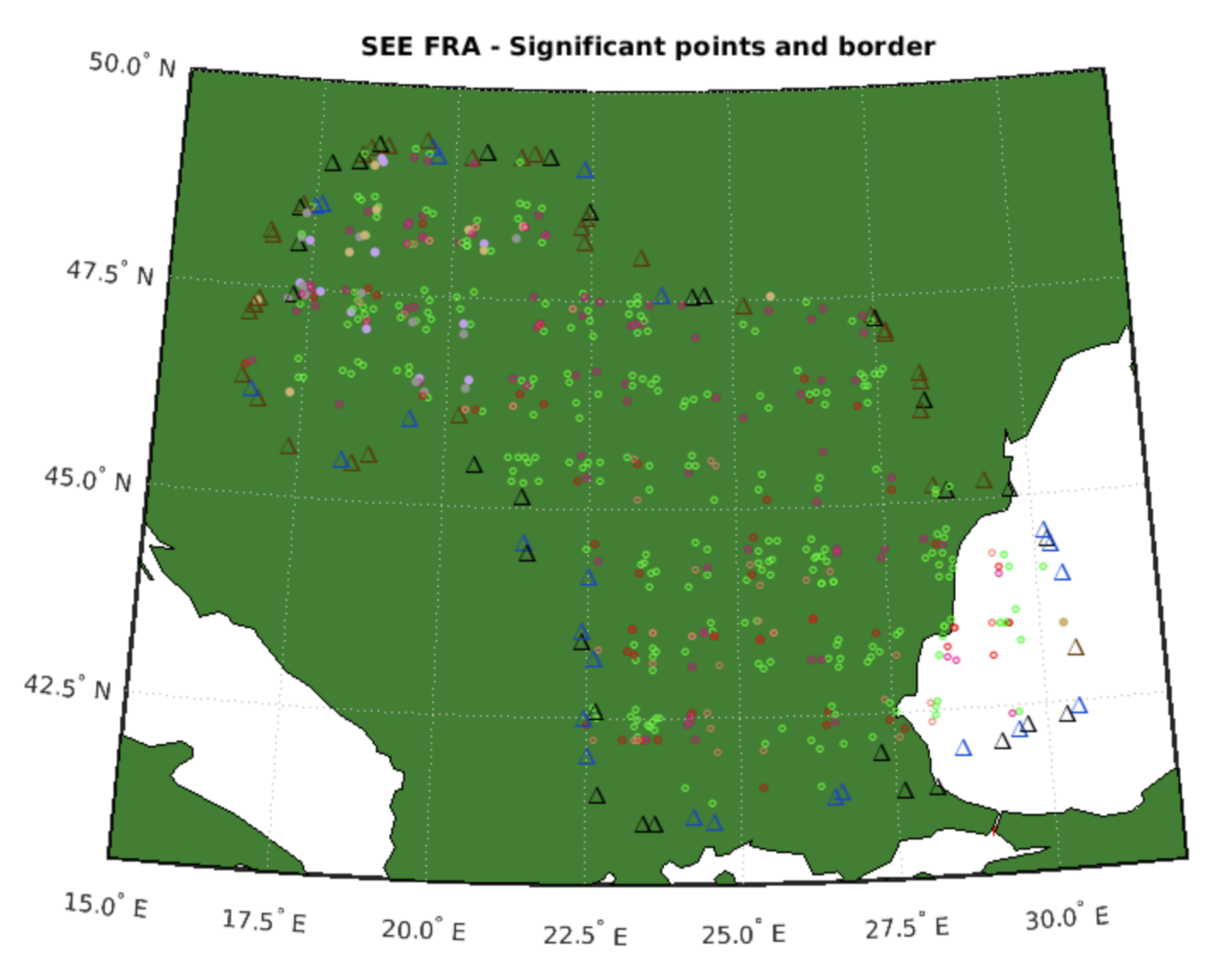
By using the graph GFRA we define a complex network. In this network, each vertex of the Graph GFRA is defined by FRA significant points (see Figure 4 and [11], Algorithm Section). We define the FRA network as an object that contains the pairs where , is a set of the FRA significant points, and are GPS coordinates of the given point. We do not mention the edges of the network here. We assume that each vertex (significant point) can be connected to every vertex (significant point) within the area FRA. This network is called the Free Route Airspace Network and is denoted by , see ([11], Algorithm section, A[2]—The Vertex SEE FRA).
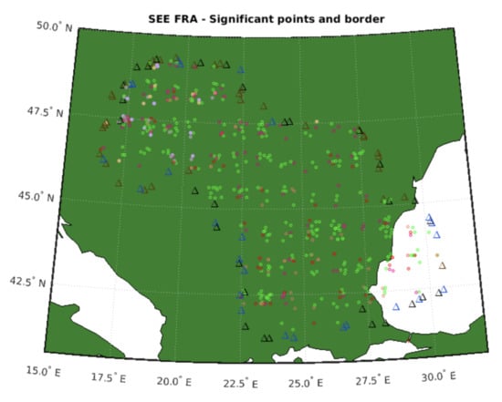
Figure 4.
SEE FRA significant points.
Note: contains all significant points (GPS coordinates of the points) in the FRA area . Each FRA significant point has assigned information to which FRA area it belongs.
5. Airspace Axiom Characteristics
FRA efficiency provides a rule that the flight can enter and exit the concerned airspace only once. With the aim of flight optimization, the idea arose to study the basic mathematical properties of airspace. The basic mathematical properties of airspace can best be expressed by specifying the basic axiom. These propositions are based on the FRA’s analysis mentioned above. The pronounced axioms define the general characteristics of airspace.
5.1. A Simple Polygon
Now, we construct horizontal boundary for each airspace . The boundary is an FRA polygon that is defined by special significant points (type 1. or 3. and country information). This polygon is a 2D (two-dimensional) projection of airspace into the plane and represents the FRA airspace. We use a 2D model because the significant points that create the airspace have two coordinates, latitude and longitude. We need to define terms polygon and simple polygon before pronouncing the axioms.
Definition 1.
The polygon is a two-dimensional closed polyline consisting of a set of line segments (sides or edges) connected such that no two segments cross. The points where two edges meet are the polygon’s vertices.
Definition 2.
The simple polygon is a polygon that does not intersect itself and encloses only one region (polygon is simply connected).
A Spatially Bounded Airspace Axiom
For each airspace there is a simple polygon
where significant entry or entry and exit points of airspace are polygon’s vertices, for .
Polygon is called the airspace polygon. We denote the number of polygon’s vertices as . We can see in Figure 4 such a polygon for airspace SEE FRA. Now we will show that an airspace polygon is simple.
5.2. No Loop Property
Traffic overflying the concerned airspace is to be planned directly between FRA Entry, FRA Intermediate, and FRA Exit Points. This means that once the flight enters the airspace via the FRA Entry Point, then the next point that has to use is the FRA Intermediate Point → the flight cannot make the circle and use again the FRA Entry Point. The same applies for the FRA Intermediate Points (after using this type of point, the flight has to proceed to the next FRA Intermediate Point or the FRA Exit Point) and for the FRA Exit Points (after using this type of point, the flight has to exit the airspace; it cannot make the circle and to come back to the same point).
Assumption 1.
The airspace polygondoes not contain a loop. (No loop property).
5.3. No Hole Property
Wherever FRA is implemented, the whole area that belongs to the concerned state and where air traffic control of that country is provided has to be covered. According to the ERNIP Part 1, FRA forms an integral part of the overall European ATM network and flights remain subject to air traffic control. From that, we can assume the no hole property of the airspace polygon.
Assumption 2.
The airspace polygonhas one region (airspace does not contain a hole—no hole property).
Note that in fact the polygon has only n vertices (not ), because the first and last vertices are identical. The notation from relation (4) makes it possible to express that a polygon is a closed polyline.
5.4. Airspace Polygon Creation
In this section airspace polygon creation will be discussed. We start the section with the definition of the convex set, convex polygon and convex hull.
Definition 3.
A set S is convex if for any two points the line segment .
Definition 4.
A convex polygon is a polygon that is the boundary of a convex set.
Definition 5.
The convex hull of set S is the smallest convex polygon containing the points of S. The convex hull of the set S is denoted by .
Note, we know more algorithms for finding a convex hull for a set of points. Such an algorithm can be found in the work [16].
The method for creating an airspace polygon has several steps.
- (1)
- The significant point selection is the first step in our method.Suppose that is the set of all significant points of airspace . For the construction of the airspace polygon, it is necessary to select significant points from this set, which are Entry or Entry and Exit points.Let’s markset of all Entry or Entry and Exit points of airspace and it convex hull .
- (2)
- The second step is the construction of a convex hull.Suppose that and Convex hull of set is a convex polygon containing vertices from S. For simplicity, assume that the convex polygon is formed from points , and .
- (3)
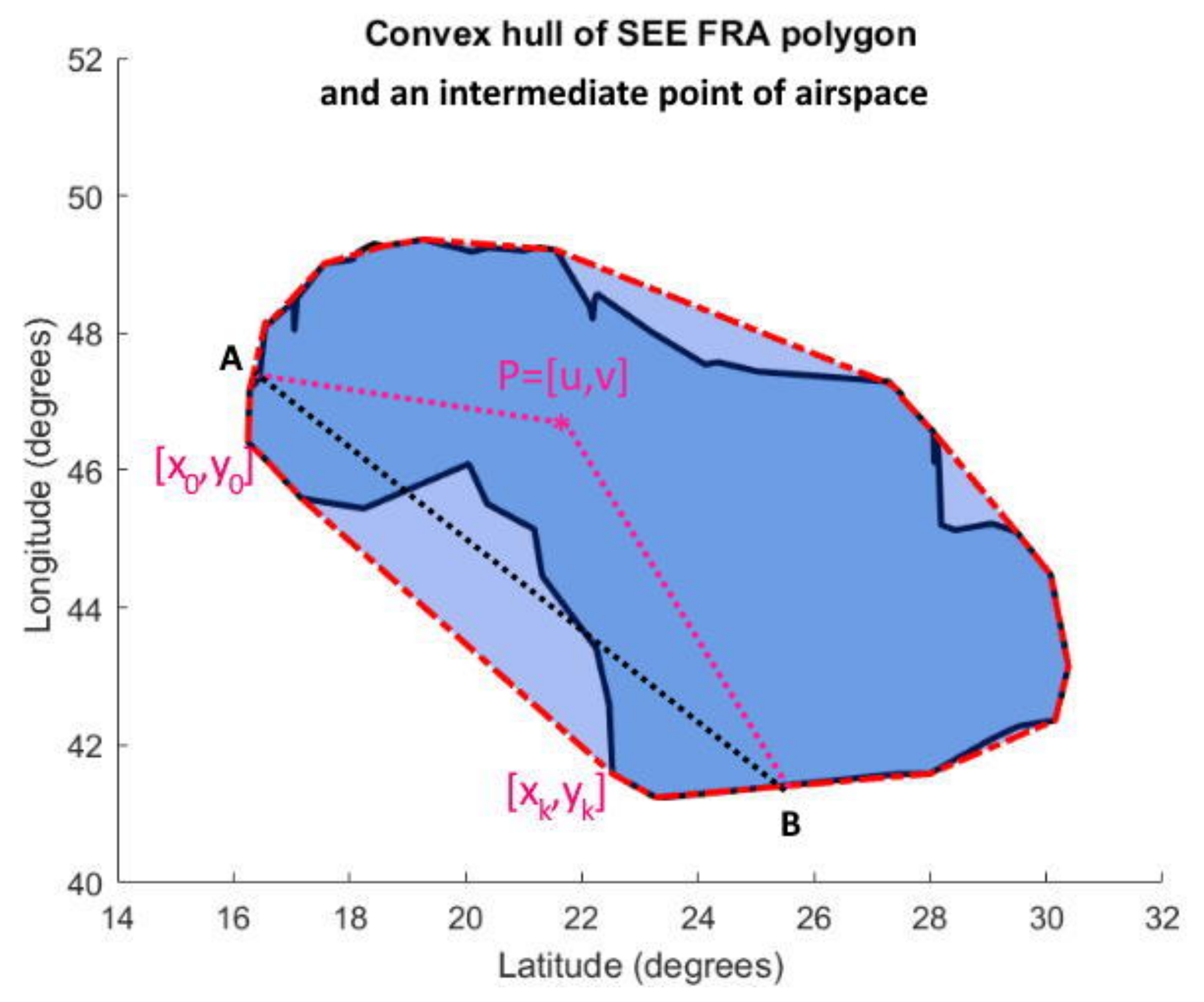
- The third step is the polygon extension - defining a polyline between the vertices and for all .We can create without loops a sequence of points , for that form the boundary of airspace for each section (see Figure 5).Note, this method step is non-algorithmic. We define the neighborhood points according to geographical conditions.
- (4)
- The fourth step is the renumbering polygon vertices.
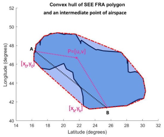 Figure 5. SEE FRA airspace polygon and its convex hull.Figure 5. SEE FRA airspace polygon and its convex hull.
 In addition, we need to determine the order of the points as they follow each other, the point indices are renumbered.The output of our method is the airspace polygonThe designation means that significant point on airspace polygon has latitude and longitude and this point is entry () or entry and exit (). In addition, the point is the vertex of the airspace polygon. Note, it is possible to construct such a polygon only for entry or only for (entry and exit) points.
Let’s note that, we can define the starting and ending point of polygon as follows
We have shown that for any set of significant points of airspace it is possible to construct a simple airspace polygon, which means the horizontal boundary of airspace. The airspace polygon exists in the plane (on the 2D map) and on the sphere, on the surface of the earth.
It should be noted, one of the rules in FRA is that we can enter and exit the airspace only once during one flight. This rule does not imply that the airspace polygon is convex. When an airspace polygon is convex, flights are implemented on a line between any entry and exit points of that airspace. When the airspace polygon is not convex, some flights are made on a polyline, which consists of lines and points where the direction of flight has changed. In Figure 5 we can see such an intermediate point P. It is not possible to fly in a straight line between entry point A and exit point B, as we would have to leave airspace and then return.
Another rule of FRA is that during one flight, we cannot use more than once the same FRA significant point. In other words, we can enter into FRA significant point only once. This FRA significant point can be entry, exit or intermediate.
6. Conclusions
The FRA airspace is defined by special, significant points. The significant point coordinates are expressed by longitude and latitude in a geodetic coordinate system. In our work, we have identified an axiom that defines airspace. Each airspace is given by a simple polygon of significant entry or (entry and exit) points. This polygon defines the horizontal boundary of airspace. The polygon does not contain holes and loops.
The publication was also created to support an Internet of Things project. Special sensors are to create a monitoring system in the project to protect isolated and high-risk populations against the spread of viral diseases. The common point between the FRA or airspace and the monitoring system are the significant points and a simple polygon on Earth’s surface, which defines the investigated area.
Author Contributions
Conceptualization, P.S. and M.F.; methodology, P.S. and M.F.; software, P.S. and M.F.; formal analysis, M.B.; resources, M.F.; data curation, P.S. and M.F.; writing—original draft preparation, P.S. and M.F.; writing—review and editing, P.S. and M.F.; visualization, P.S. and M.F.; supervision, P.S. and M.F.; project administration M.B. All authors have read and agreed to the published version of the manuscript.
Funding
This research was funded by European Regional Development Fund under the Operational Programme Integrated Infrastructure, grant number, ITMS code 313011AUP1.
Data Availability Statement
It should be noted that all algorithms work with the research data that are freely available online. Hence, all outputs are only estimations and are not to be used for operational purposes. Our data are stored in the clouds, see ([11], Data and Data Structures). The main documentation of the FRA system can be found in references ([11], Documentation).
Acknowledgments
This work was supported by the project Mobile Monitoring System for the Protection of Isolated and Vulnerable Population Groups against Spread of Viral Diseases, ITMS code 313011AUP1. The authors, gratefully acknowledge European Regional Development Fund under the Operational Programme Integrated Infrastructure and Výskumná agentúra—Research Agency for the technical and financial support. The authors would like to thank the anonymous referees for their helpful comments and constructive advices to improve the article.
Conflicts of Interest
The authors declare no conflict of interest.
References
- Szabó, P.; Ferencová, M.; Železník, V. Cloud Computing in Free Route Airspace Research. Algorithms 2022, 15, 123. [Google Scholar] [CrossRef]
- Drupka, G.; Majka, A.; Rogalski, T.; Trela, L. An Airspace Model Aplicable for Automatic Flight Route Planning inside Free Route Airspace. Zesz. Nauk. Politech. Rzesz. 2018, 35, 5–18. [Google Scholar] [CrossRef][Green Version]
- Alieksieiev, V. Air Space Routing and Flights Planning: A Problem Statement and Discussion Of approaches to Solution. Math. Model. 2018, 2, 139–143. [Google Scholar]
- Samolej, S.; Dec, G.; Rzonca, D.; Majka, A.; Rogalski, T. Regular graph-based free route flight planning approach. Aircr. Eng. Aerosp. Technol. 2021, 93, 1488–1501. [Google Scholar] [CrossRef]
- Lawrence, J.L. Celestial Calculations—A Gentle Introduction to Computational Astronomy; The MIT Press: Cambridge, MA, USA; London, UK, 2019; ISBN 978-0-262-53663-9. [Google Scholar]
- Smart, W.M. Textbook on Spherical Astronomy, 6th ed.; Cambridge University Press: Cambridge, UK, 1977; ISBN 978-0-521-29180-4. [Google Scholar]
- Digital Imaging and Remote Sensing Image Generation. Coordinate Systems. Available online: http://dirsig.cis.rit.edu/docs/new/coordinates.html (accessed on 14 April 2022).
- Van Sickle, J. Basic GIS Coordinates; CRC Press. Taylor & Francis Group: Boca Raton, FL, USA, 2017; ISBN 978-0-367-57351-5. [Google Scholar]
- FAA. Federal Aviation Administration. Airspace. 2022. Available online: https://tinyurl.cc/airspace-faa (accessed on 15 May 2022).
- IVAO. International Virtual Aviation Organisation. Available online: https://tinyurl.com/fl-IVAO (accessed on 14 April 2022).
- Ferencová, M.; Szabó, P. FRA Research Cloud. Available online: https://tinyurl.com/fra-research-cloud/ (accessed on 14 April 2022).
- Ferencová, M.; Főző, L.; Szabó, P. Free Route Airspace—Graphs, Networks, Algorithms. In Proceedings of the 2021 New Trends in Aviation Development (NTAD), Košice, Slovakia, 25–26 November 2021; pp. 31–36. [Google Scholar] [CrossRef]
- Newman, M.E.J. Networks: An introduction; Oxford University Press Inc.: New York, NY, USA, 2010; ISBN 978-0-199-20665-0. [Google Scholar]
- Sallan, J.M.; Lordan, O. Air Route Networks through Complex Networks Theory; Elsevier Science Publishing Co. Inc.: Amsterdam, The Netherlands, 2019; ISBN 978-0-128-12665-5. [Google Scholar]
- Ferencová, M.; Šulej, R.; Szabó, P. The follow-up on the Free Route Airspace Implementation in Slovakia with the proposed optimization model. In Proceedings of the 2018 XIII International Scientific Conference—New Trends in Aviation Development (NTAD), Košice, Slovakia, 30–31 August 2018; pp. 55–58. [Google Scholar] [CrossRef]
- Bradford, C.B.; Dobkin, D.P.; Huhdanpaa, H. The quickhull algorithm for convex hulls. ACM Trans. Math. Softw. 1996, 1996 22, 469–483. [Google Scholar]
Publisher’s Note: MDPI stays neutral with regard to jurisdictional claims in published maps and institutional affiliations. |
© 2022 by the authors. Licensee MDPI, Basel, Switzerland. This article is an open access article distributed under the terms and conditions of the Creative Commons Attribution (CC BY) license (https://creativecommons.org/licenses/by/4.0/).

