Abstract
Demand estimation in a water distribution network provides crucial data for monitoring and controlling systems. Because of budgetary and physical constraints, there is a need to estimate water demand from a limited number of sensor measurements. The demand estimation problem is underdetermined because of the limited sensor data and the implicit relationships between nodal demands and pressure heads. A simulation optimization technique using the water distribution network hydraulic model and an evolutionary algorithm is a potential solution to the demand estimation problem. This paper presents a detailed process simulation model for water demand estimation using the particle swarm optimization (PSO) algorithm. Nodal water demands and pipe flows are estimated when the number of estimated parameters is more than the number of measured values. The water demand at each node is determined by using the PSO algorithm to identify a corresponding demand multiplier. The demand multipliers are encoded with varying step sizes and the optimization algorithm particles are also discretized in order to improve the computation time. The sensitivity of the estimated water demand to uncertainty in demand multiplier discrete values and uncertainty in measured parameters is investigated. The sensor placement locations are selected using an analysis of the sensitivity of measured nodal heads and pipe flows to the change in the water demand. The results show that nodal demands and pipe flows can be accurately determined from a limited number of sensors.
1. Introduction
A water distribution system (WDS) performs the crucial role of supplying safe drinking water to the public. The main goal in WDS operation and control is to meet the desired water demand while ensuring the appropriate water quality and pressure is met in all the nodes. Water flow from the sources to the demand nodes is a continuous event with time-varying flow rates determined by water demand schedules. Nodal demands are state variables of interest in WDS operation because they are the driving inputs that determine the nodal pressures and pipe flow rates measured in the field. State estimation is the process of computing unknown network conditions from the knowledge of available measurements and other known network parameters [1]. A water demand estimation algorithm coupled with a WDS model forms a critical component for supervisory control and data acquisition (SCADA) systems.
In water demand estimation, the nodal demands are the unknown state variables, while pressure heads and pipe flows are determined from field measurements. Because of the complexity of pipe connections in large water distribution networks and the associated cost, only a few locations are selected for sensor placement. The accuracy of state estimation relies on the available field measurements, which are constrained by the number of installed pressure and flow sensors. The problem of sensor placement has been addressed in literature by considering budget constraints and the quality of measured data [2], location impact metrics [3,4], and the time taken to detect contamination events [5,6]. The number of sensor locations may also be reduced by clustering water demand nodes into groups [7], grouping nodes according to water quality characteristics [8], and using reduced network models [9]. A ranking technique is used to select nodes for locating pressure sensors in [10]. Loop flows are estimated in [11] using known nodal demands in order to address the problem of a low measurement redundancy. The installation of sensors in a WDS is also subject to site accessibility and consent from the landowner. With the observed constraints in sensor placement, the estimation of nodal demands and unmeasured pressure heads or pipe flows with data obtained from a limited number of locations is a current research problem. Because of the large number of unknown parameters compared to the available measurement data, the estimation problem is underdetermined. The contribution of this work is the formulation of a simulation optimization technique that estimates both nodal demands and unmeasured pressure heads when the number of measurements is less than the number of parameters to be estimated. The objective function minimizes the absolute error of the measured parameters using the particle swarm optimization (PSO) algorithm. The sensor placement locations are selected using an analysis of the sensitivity of measured nodal heads and pipe flows to the change in the water demand. The sensitivity of the estimated parameters to the number of sensors, the uncertainty in demand multiplier discrete values, and measurement errors is also investigated.
2. Literature Review
Knowledge of the status of a water distribution network is realized by means of state estimation techniques that yield a set of variables that fully describe the status of the system. State estimation in WDSs is expressed using a nonlinear measurement model [12]:
where is the vector of available measurements (pressure heads, flows, and demands), is the state vector formed by nodal heads and fixed-head node flows, and is a zero-mean random vector that models the measurement errors. The measured flows and pressure heads, combined with the hydraulic energy and mass conservation laws, provide the necessary system of equations used to implement the state estimation model defined in Equation (1).
Loop flows are estimated using weighted least squares in [11,13,14] from known nodal demands. Water demands are estimated using a Monte Carlo simulation with Kalman filtering in [15,16]. Genetic algorithms are used to calibrate predicted water demand data in [17,18]. The underdetermined nodal demand problem is solved in [19] using singular value decomposition (SVD) and in [20], by combining SCADA data and demand estimates. Compared to classical methods such as the weighted least squares and Langrangian multipliers, the SVD technique and evolutionary algorithms have the potential of estimating nodal demands when the number of measurements is less than the number of parameters to be estimated. In [11], known demand estimates are used in conjunction with measurements in order to ensure that the estimation problem is not underdetermined.
In this study, a simulation optimization technique based on the discrete event simulation paradigm was used to implement the PSO algorithm. The optimization algorithm was used to estimate nodal demands and unmeasured nodal heads and pipe flows. EPANET software [21] was used to implement and solve the WDS hydraulic model. The optimization algorithm was used for estimation while results from EPANET were used to simulate measured values one time step ahead. The results are compared with recent related works.
3. Methodology
3.1. Objective Function
The water demand estimation problem, which estimates the variation in nodal demand using information from measurements taken by pressure/flow sensors, is defined as a minimization of the absolute error:
where and are the measured nodal head and pipe flow rate at node i and pipe j, respectively; and are the simulated head and flow rate at node i and pipe j, respectively; and and are the number of head and flow sensors installed in the network. The constraints are the law of conservation of mass at each node, the law of conservation of energy in each loop, and minimum pressure head requirements. The water demands at each node are the decision variables of the optimization problem.
3.2. Modeling of Water Demand Multipliers
The node demand data used in a water distribution network analysis is normally based on estimates derived from monthly water meter readings. The nodal demand profiles are composed of static distribution factors, which vary with the consumer type. The water distribution system is classified into supply areas according to land use, such as residential, commercial, and industrial areas. The general demand pattern for the different consumer types in a 24 h period is shown in Figure 1. The demand pattern data is obtained from [22].
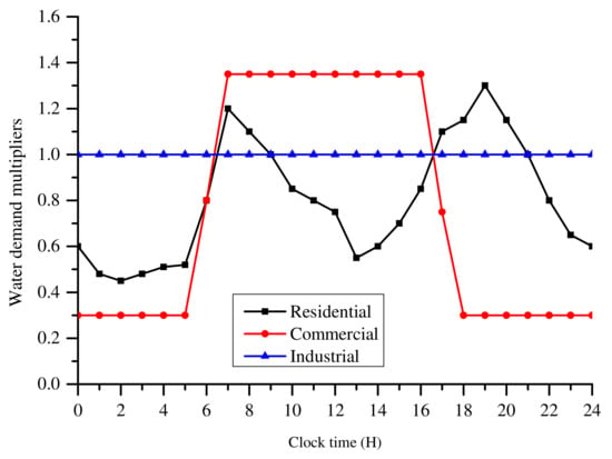
Figure 1.
Demand curves for different user types in a period of 24 h.
In order to solve the water demand estimation, the problem of how to set nodal demands used as the driving inputs for generating measured parameters in Equation (2) has to be addressed first. The nodal demand for node i at time step k is given by
where is the nodal demand, is the demand multiplier for node i, and is the base demand for node i. The decision variables of the optimization problem are therefore conveniently represented as the set of demand multipliers at each time step k, where is the total number of nodes in the water distribution network.
3.3. Process Simulation Model
The demand estimation problem is solved using the discrete event simulation optimization scheme shown in Figure 2. A discrete event simulation scheme eliminates the need for an explicit time loop. The estimation starts with the hydraulic simulator running with data from a defined demand–user pattern in order to generate the measured values of pressure head () and pipe flow (). The measured values are obtained from the selected sensor locations. The optimization algorithm uses randomly generated nodal demand multipliers to run the hydraulic simulator in order to generate the simulated values of the pressure head () and pipe flow (). At the end of each iteration of the optimization algorithm, the simulated data is passed to the optimization model. The objective Equation (2) function is used to evaluate the fitness of nodal demand multipliers. The optimization algorithm calibrates the demand multipliers on the basis of the fitness obtained. The hydraulic simulator runs in the steady-state mode.
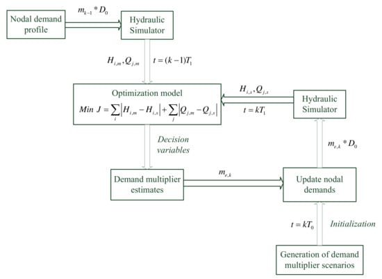
Figure 2.
Methodology for estimation of water demand using an optimization algorithm.
The PSO algorithm [23], the optimization model, and the simulation optimization scheme of Figure 2 were implemented in C/C++. The EPANET software package source code in C and the programming toolkit [24] were utilized. The constraints of the optimization problem were solved by EPANET. The optimization algorithm was interfaced with EPANET using the interface module developed in [25].
The simulation was carried out by defining discrete event times that defined the transition of states in the system. An evolutionary algorithm such as PSO generates a population of potential solutions that are used to run the system, and the fitness of each solution is evaluated using Equation (2). A discrete event time is chosen as the time each potential solution of the optimization algorithm takes to run the system. The parameters of each potential solution are a set of demand multipliers that are updated at the end of each iteration. The parameters of each potential solution are passed to the hydraulic solver during the initialization phase in order to evaluate the fitness. Proper initialization ensures that the fitness of each potential solution is evaluated with the same initial conditions. After a simulation time equal to , where is N is the population size, the fitness of each set of demand multipliers is evaluated and the optimization algorithm re-calibrates the demand multipliers. The hydraulic solver evaluates the reference values (measured values) for the optimization algorithm one time step ahead, that is, at . In this paper, a discrete event time of = 0.01 s was used. The nodal water demands for each time step during the 24 h consumption period are estimated using demand multipliers, which are used to compute the actual demand using Equation (3). The demand multipliers are defined in the continuous range as shown in Figure 1. In order to increase the convergence speed of the estimation process, the demand multiplier range is converted into the discrete range with step increments. Step sizes of 0.01 and 0.05 were used and the results were compared. An integer coding scheme was used, for which the PSO particles were used to search for the optimal index in the defined range. Because the motion of the PSO particles during the search process is continuous, the position of the particle was rounded to the nearest integer. The particle position corresponds to an array index where the actual demand multiplier is stored.
3.4. Selection of Sensor Placement Locations
The sensor placement locations are selected on the basis of the sensitivity to the change in the water demand. The sensitivity matrix [26] is expressed as
where each element measures the effect of change in the nodal demand on the measurement at a selected pipe link or node. The sensitivity matrix has been used to select sensor placement locations for leakage detection in [27,28].
A simulated change in the water demand in all the nodes is used to generate a pipe flow sensitivity matrix and a nodal head sensitivity matrix. A change in the nodal demand of 1.5 liters per second (LPS) at the two nodes of each pipe link is considered at each step. The measurement locations are ranked according to the variance of the measurements at each location. The best locations for placing sensors are those that experience the highest variability in measurements as a result of change in the nodal demand. This simple approach was used in this study to select the measurement locations in a real network with a large number of pipes and nodes.
4. Simulation Results and Discussion
Simulation experiments were performed using three case studies. A small water network consisting of 9 nodes, 12 pipes, 1 pump and 1 tank was used to perform the simulation experiments in case studies I and II. The network is available in EPANET as example “Net1.net” [21]. The water network was as is shown in Figure 3. Case study I considers the water demand estimation using measurements from pressure sensors only, while Case study II considers measurements from both pressure sensors and flow sensors. All the nodes in the Net1 network share the same hourly demand multipliers, but each node has an independently defined base demand. Case study III considers a medium-sized network that represents the operation of a real water distribution network. The case studies utilized the optimization algorithm to estimate hourly nodal demands for each hour in a 24 h period.
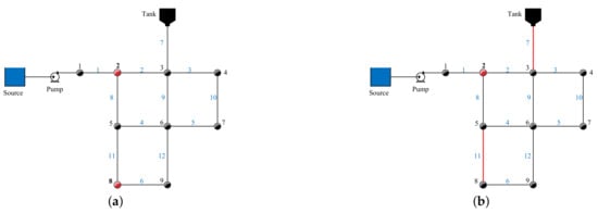
Figure 3.
Water distribution network for case studies: (a) case study I, and (b) case study II.
4.1. Case Study I: Estimation of Nodal Demands with Measurements from Pressure Head Sensors
The sensor placement locations were identified using an exhaustive search. Tests were carried out starting with an ideal case where pressure sensors were placed in all the nodes. The sensors were then reduced sequentially while the performance was observed. Initial results showed that the water consumption at node 2 could not be accurately estimated without placing a pressure sensor at node 2. Node 2 was the source node that supplied the entire network. Node 1 was not selected for sensor placement as there was no water consumption at the node. One sensor was therefore permanently placed at node 2, while the sensors at the other locations were sequentially removed. Good results were obtained with only two sensors placed at nodes 2 and 8.
To assess the suitability of the identified locations, the nodal head sensitivity matrix of the network was generated and the variance of each row was used to rank the nodes. The results of the nodal head sensitivity ranking are shown in Figure 4. The pressure head at node 9 was the most sensitive, while that of node 3 was the least sensitive. The results showed that further engineering judgement was required in order to select the locations, as both nodes 8 and 9 were connected to the same pipe link. Nodes 2 and 5 also shared a common pipe link. It was also observed that node 1 had zero demand. Nodes 2 and 8 were therefore good locations to place pressure head sensors.
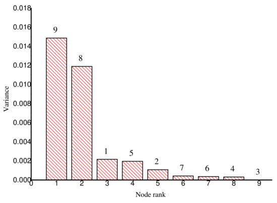
Figure 4.
Nodal head sensitivity for Net1 network.
The PSO initialization parameters for the case study are given in Table 1. The first simulation experiment was carried out using step increments of 0.05 to encode the demand multipliers. The demand multipliers lay in the range from 0 to 2.0. Because of the stochastic nature of the optimization process, nodal demand estimates from 30 simulation runs were averaged and used for comparison. The estimated nodal demands for nodes 2, 4, 6 and 9 using a demand multiplier step increment of 0.05 are shown Figure 5. A summary of the average estimated and actual values of the water demands for the 24 h period is given in Table 2. The results in Table 3 were converted to gallons per minute (GPM) for easy comparison. The results were compared with those reported in [17] using a genetic algorithm (GA) model. The base demands for nodes 7, 8 and 9 in the GA model were different to those in the model used in this paper. Estimation was carried out in [17] using three pressure sensors placed at nodes 4, 6, and 8 and with a demand multiplier step increment of 0.02. The results in Table 2 show that the estimated demands for nodes 3, 6 and 7 were comparable, while the PSO model gave improved results at all the other nodes. The results obtained in this paper show that placing a pressure sensor at the source node contributes to an improvement in the estimated water demand. The results obtained from 30 (independent optimization trial) runs in this study compare with those obtained in 100 runs of the GA model [17]. There is therefore a need for further analyses of the sensitivity of the estimation error on the number of optimization runs used to obtain the average demand. A large number of optimization runs increases the computation time. A low computation time is necessary for the near-real-time on-line monitoring and control of water distribution systems.

Table 1.
Case study I & II: Initialization of particle swarm optimization (PSO) parameters.
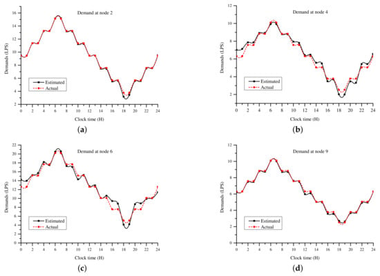
Figure 5.
Case I: Demand estimation at nodes (a) 2, (b) 4, (c) 6, and (d) 9.

Table 2.
Case I: Estimated nodal demands (liters per second—LPS).

Table 3.
Case I: Comparison of estimated nodal demands (gallons per minute—GPM) using particle swarm optimization (PSO) and the genetic algorithm (GA).
The second simulation experiment was carried out by adding noise to the nodal demands used to generate the measured values. White Gaussian noise with a zero mean and variance of 0.1 was added to the hourly nodal demand multipliers. The demand multipliers with noise scenario is shown in Figure 6. The purpose of adding noise was to investigate the sensitivity of estimating the water demand to uncertainty in the step increment of the demand multipliers. The results obtained using step increments of 0.05 and 0.01 were compared. A resolution of 0.05 resulted in a single nodal demand multiplier search space of 40, while that of 0.01 resulted in a search space of 200. The nodal demand estimates from 30 simulation runs were averaged and used for comparison. The estimated nodal demands for nodes 2, 4, 6, and 9 are shown in Figure 7. A summary of the estimated and actual values of the water demands for the 24 h period is given in Table 4. The values are highly correlated with R = 0.981 and R = 0.991 for = 0.05 and = 0.01, respectively. There was therefore no significant difference in the water demand estimates determined using a step increment of 0.05 or 0.01 when the discrete values of the demand multipliers had an uncertainty of ±0.1.
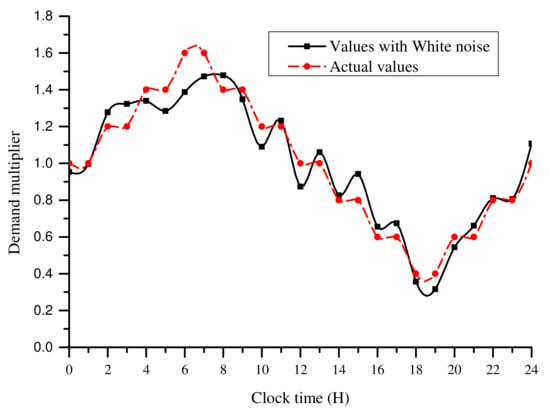
Figure 6.
Nodal demand multipliers with added white noise.
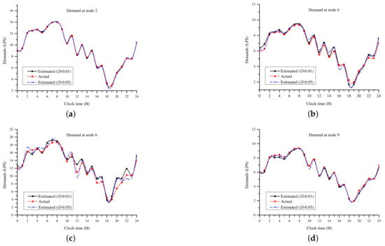
Figure 7.
Case I: Estimation of water demands with demand multiplier resolutions of = 0.05 and = 0.01 at nodes (a) 2, (b) 4, (c) 6, and (d) 9.

Table 4.
Case I: Estimated nodal demands (liters per second—LPS).
4.2. Case Study II: Estimation of Nodal Demands with Measurements from Flow Sensors and Pressure Sensors
The simulation experiments in this case study were carried out by placing a pressure sensor at node 2 and flow sensors at pipes 7 and 11. Pipe 7 was selected as it supplied node 3, which had the highest error margin, as shown in Table 4.
To assess the suitability of the identified locations, the pipe flow rate sensitivity matrix of the network was generated, and the variance of each row was used to rank the pipe links. The results of the pipe flow rate sensitivity ranking are as shown in Figure 8. The pipe flow rate at pipe 9 was the most sensitive, while that of pipe 6 was the least sensitive. The results also show that further engineering judgement was required in order to select the locations, as pipe links 2, 7 and 9 were connected to node 3.
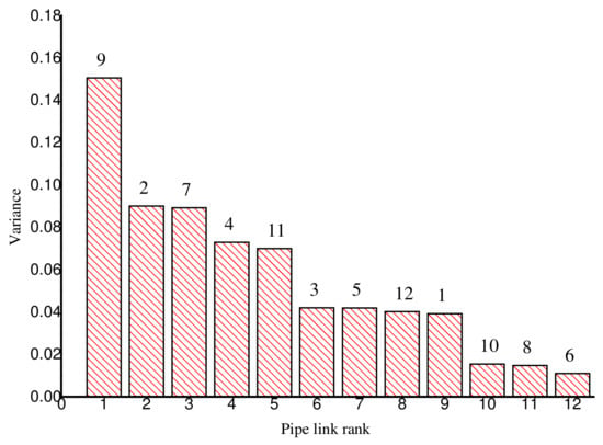
Figure 8.
Pipe flow rate sensitivity for Net1 network.
Gaussian white noise was used to add a measurement uncertainty equal to ±10% of the measured value. A demand multiplier step increment of 0.05 was used in the simulations.
A summary of the averaged nodal demand estimates and pipe flow estimates are given in Table 5 and Table 6. The averaged estimated nodal pressure heads are shown in Figure 9. The pipe flow rates were more sensitive to variation in nodal demands, compared to the pressure heads. The estimated flows for pipes 2, 5, 6, and 7 are shown Figure 10 and the estimated flows for pipes 3, 8, 10, and 11 are shown Figure 11. It can be observed from the results in Table 6 and Figure 10 and Figure 11 that the pipes with low flow rates, for example, pipes 3, 5 and 6, had the highest error margin during estimation. The results show that these were the pipes with the highest sensitivity to changes in the water demand. The 24 h average pipe flow rates of Table 6 show that pipe 5 had an estimated average flow rate of 7.57 L/s with an error of 0.5%. However, the hourly flows in Figure 10b show that the estimated flow rate of pipe 5 had a correlation of R = 0.567 with the actual values. The flow rate of pipe 6 had an average estimation error of 8.3% and a correlation of R = 0.721 between the hourly estimated values and the actual values. It is therefore concluded that the correlation coefficient between actual and estimated values is a better measure of the quality of estimation, especially in pipes with low flow rates.

Table 5.
Case II: Estimated nodal demands (liters per second—LPS) with uncertain measurements.

Table 6.
Case II: Estimated pipe flows (liters per second—LPS) with uncertain measurements.
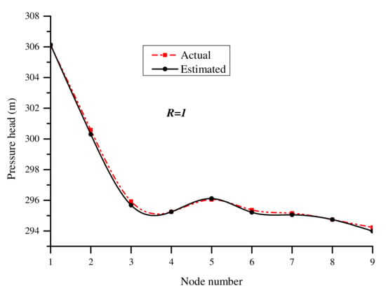
Figure 9.
Case II: Estimated nodal pressure heads using uncertain measurements.
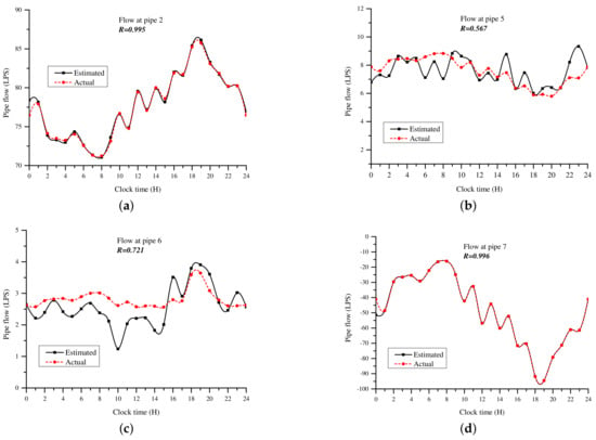
Figure 10.
Case II: Estimation of pipe flow rates in pipes (a) 2, (b) 5, (c) 6, and (d) 7 using uncertain measurements.
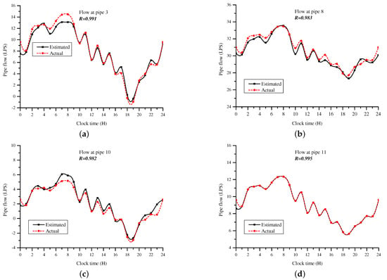
Figure 11.
Case II: Estimation of pipe flow rates in pipes (a) 3, (b) 8, (c) 10, and (d) 11 using uncertain measurements.
The nodal demands estimated in case II had a maximum error margin of 7.9% at node 4, while those estimated in case I had a maximum error of 12.9% at node 3. The estimation error at node 3 reduced to 1.3% in case II. This could be attributed to the flow sensor placed at pipe 7 in case II. It is therefore concluded that the utilization of both pressure and flow sensors improves the overall results obtained during estimation.
4.3. Case Study III: Estimation of Water Demand in a Larger Water Network
The third case study considers a medium water network that consists of 40 pipes, 35 nodes, 1 pump station, and 1 water tank. The network is available in EPANET as example “Net2.net” [21]. The pump station was modeled as a node with a negative demand using the provided demand profile. The network data modeled the operation of a real network. The water demand of each node was independently defined and the water consumption represented a combination of different user types. The network layout is shown in Figure 12.
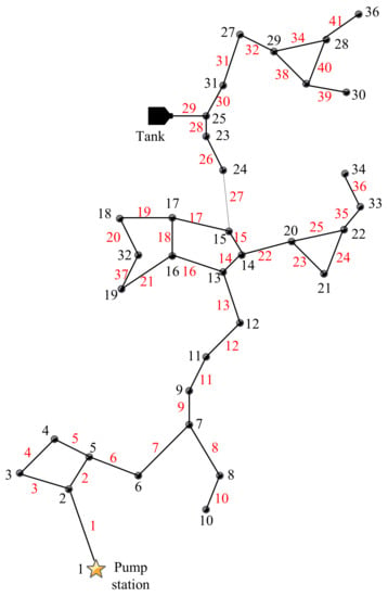
Figure 12.
Case III: Water distribution network.
In this case study, the PSO algorithm was initialized to run with a population of 100 and 500 iterations. A demand multiplier range of 0 to 4.0 was used with a step increment of 0.02. The upper limit of the demand multiplier range was chosen by analyzing the nodal base demands and the provided demand profile data.
The sensitivity matrix was utilized to select the locations for placing flow and pressure sensors. The results of the nodal head and pipe flow rate sensitivity ranking are as shown in Figure 13 and Figure 14, respectively. The results show that the pressure of nodal heads nearer to the pump station was more sensitive to the change in the water demand. The flow rates of pipe links were also generally more sensitive to the change in the water demand, compared to the nodal heads. Considering a case in which three pressure sensors and six flow sensors were available for placement, nodes 3, 6 and 10 and pipe links 13, 14, 15, 27, 28, and 30 were selected.
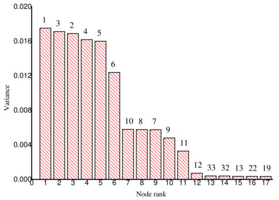
Figure 13.
Nodal head sensitivity for Net2 network.
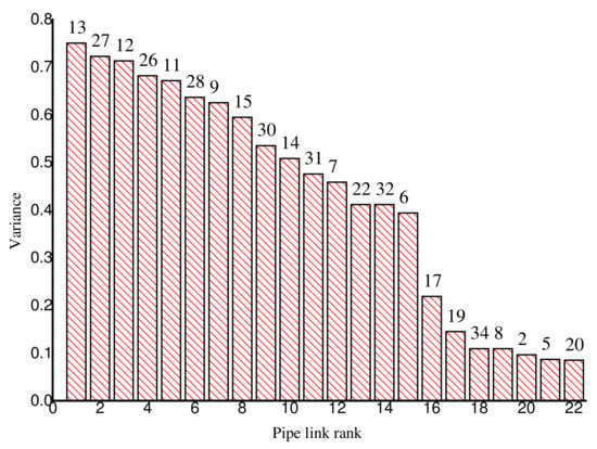
Figure 14.
Pipe flow rate sensitivity for Net2 network.
The results for the estimated average water demand for a 24 h period are as shown in Figure 15 and Figure 16. The results show that the nodes with a water demand of less than 0.3 LPS, for example, nodes 7, 32, 33 and 35, had estimation errors of more than 40%. The average of the estimation error for the actual values was 15.0%, while the average estimation error of the absolute values was 22.4%. The estimation error of the actual values was lower because the negative and positive errors offset each other. The average demand estimation error in [17] was 14.7% for the same network. The largest demand estimation error in this study was 56.2% at node 32. The average demand of node 32 was 0.1 LPS. However, Figure 15 shows that the absolute estimation error at node 32 was not significant. The results show that the nodes with low water demands had a high contribution to the overall water demand estimation error.
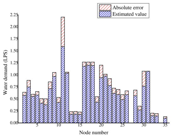
Figure 15.
Case III: Estimated nodal water demands and absolute error.
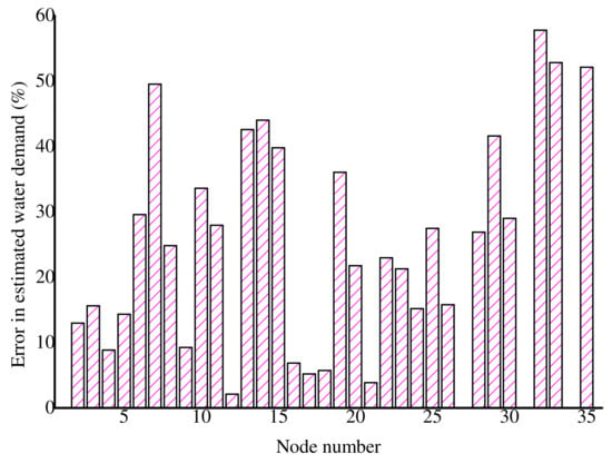
Figure 16.
Case III: Absolute error (%) in estimated nodal water demands.
The estimation process of 500 iteration runs for a real-time of 62 s on a 2.6 GHz computer with 4 GB of memory. Further research is therefore required in order to reduce the estimation errors and improve the computation time. The proposed process simulation model is suitable for implementing and comparing the performance of evolutionary algorithms in water demand estimation. The future work for this study entails embedding a sensor placement algorithm in the developed process simulation model in order to assess the sensitivity of sensor placement locations on the water demand estimation errors.
5. Conclusions
As a result of budgetary and other physical constraints, there is a need to estimate water demands in water distribution networks from a limited number of sensors. A detailed process simulation model for water demand estimation using the PSO algorithm was formulated and implemented. Nodal water demands and pipe flows were estimated when the number of estimated parameters was more than the number of measured values. The water demand at each node was determined by using the PSO algorithm to identify a corresponding nodal demand multiplier. The nodal demand multipliers were encoded with varying step sizes. The sensor placement locations were selected using an analysis of the sensitivity of measured nodal heads and pipe flows to the change in the water demand. The results show that accurate results can be determined using sensor measurements from a limited number of locations. The results also show that the estimated water demand is not sensitive to an uncertainty of ±0.1 in demand multiplier discrete values or a ±10% uncertainty in measured parameters. Further research is required in order to address the problem of embedding a sensor placement algorithm in the developed process simulation model in order to assess the sensitivity of sensor placement locations on the water demand estimation errors.
Acknowledgments
The authors would like to thank The Council for Scientific and Industrial Research (CSIR), South Africa, for financial support.
Author Contributions
Lawrence K. Letting and Yskandar Hamam conceived and designed the experiments; Lawrence K. Letting developed the algorithm code in C++ and performed the simulation experiments; Adnan M. Abu-Mahfouz contributed to the analysis and interpretation of results. The manuscript was written by Lawrence K. Letting with contribution from all co-authors.
Conflicts of Interest
The authors declare no conflict of interest.
References
- Della Giustina, D.; Pau, M.; Pegoraro, P.A.; Ponci, F.; Sulis, S. Electrical distribution system state estimation: Measurement issues and challenges. IEEE Instrum. Meas. Mag. 2014, 17, 36–42. [Google Scholar] [CrossRef]
- Sarrate, R.; Blesa, J.; Nejjari, F.; Quevedo, J. Sensor placement for leak detection and location in water distribution networks. Water Sci. Technol. Water Supply 2014, 14, 795–803. [Google Scholar] [CrossRef]
- Eliades, D.; Kyriakou, M.; Polycarpou, M. Sensor Placement in Water Distribution Systems Using the S-PLACE Toolkit. Procedia Eng. 2014, 70, 602–611. [Google Scholar] [CrossRef]
- Pourali, M.; Mosleh, A. A functional sensor placement optimization method for power systems health monitoring. In Proceedings of the IEEE 2012 Industry Applications Society Annual Meeting (IAS), Las Vegas, NV, USA, 7–11 October 2012; pp. 1–10. [Google Scholar]
- Antunes, C.H.; Dolores, M. Sensor location in water distribution networks to detect contamination events—A multiobjective approach based on NSGA-II. In Proceedings of the 2016 IEEE Congress on Evolutionary Computation (CEC), Vancouver, BC, Canada, 24–29 July 2016; pp. 1093–1099. [Google Scholar]
- Schal, S.; Bryson, L.S.; Ormsbee, L.E. A simplified procedure for sensor placement guidance for small utilities. Int. J. Crit. Infrastruct. 2016, 12, 195–212. [Google Scholar] [CrossRef]
- Jung, D.; Choi, Y.H.; Kim, J.H. Optimal Node Grouping for Water Distribution System Demand Estimation. Water 2016, 8, 160. [Google Scholar] [CrossRef]
- Qin, T.; Boccelli, D.L. Grouping Water-Demand Nodes by Similarity among Flow Paths in Water-Distribution Systems. J. Water Resour. Plan. Manag. 2017, 143, 04017033. [Google Scholar] [CrossRef]
- Preis, A.; Allen, M.; Whittle, A.J. On-line hydraulic modeling of a Water Distribution System in Singapore. In Proceedings of the Water Distribution Systems Analysis 2010, Tucson, AZ, USA, 12–15 September 2010; pp. 1336–1348. [Google Scholar]
- Ribeiro, L.; Sousa, J.; Marques, A.S.; Simões, N.E. Locating leaks with trustrank algorithm support. Water 2015, 7, 1378–1401. [Google Scholar] [CrossRef]
- Andersen, J.H.; Powell, R.S. Implicit state-estimation technique for water network monitoring. Urban Water 2000, 2, 123–130. [Google Scholar] [CrossRef]
- Bargiela, A. On-Line Monitoring of Water Distribution Networks. Ph.D. Thesis, Durham University, Durham, UK, 1984. [Google Scholar]
- Arsene, C.T.; Gabrys, B. Mixed simulation-state estimation of water distribution systems based on a least squares loop flows state estimator. Appl. Math. Model. 2014, 38, 599–619. [Google Scholar] [CrossRef]
- Jung, D.; Lansey, K. Water distribution system burst detection using a nonlinear Kalman filter. J. Water Resour. Plan. Manag. 2014, 141, 04014070. [Google Scholar] [CrossRef]
- Xie, X.; Zhang, H.; Hou, D. Bayesian Approach for Joint Estimation of Demand and Roughness in Water Distribution Systems. J. Water Resour. Plan. Manag. 2017, 143, 04017034. [Google Scholar] [CrossRef]
- Hutton, C.J.; Kapelan, Z.; Vamvakeridou-Lyroudia, L.; Savic, D.A. Real-time demand estimation in water distrubtion systems under uncertainty. In Proceedings of the WDSA 2012: 14th Water Distribution Systems Analysis Conference, Adelaide, Australia, 24–27 September 2012; p. 1374. [Google Scholar]
- Do, N.C.; Simpson, A.R.; Deuerlein, J.W.; Piller, O. Calibration of Water Demand Multipliers in Water Distribution Systems Using Genetic Algorithms. J. Water Resour. Plan. Manag. 2016, 142, 04016044. [Google Scholar] [CrossRef]
- Preis, A.; Whittle, A.J.; Ostfeld, A.; Perelman, L. Efficient hydraulic state estimation technique using reduced models of urban water networks. J. Water Resour. Plan. Manag. 2010, 137, 343–351. [Google Scholar] [CrossRef]
- Sanz, G.; Pérez, R. Sensitivity analysis for sampling design and demand calibration in water distribution networks using the singular value decomposition. J. Water Resour. Plan. Manag. 2015, 141, 04015020. [Google Scholar] [CrossRef]
- Davidson, J.; Bouchart, F.C. Adjusting nodal demands in SCADA constrained real-time water distribution network models. J. Hydraul. Eng. 2006, 132, 102–110. [Google Scholar] [CrossRef]
- Rossman, L. Epanet 2: Users Manual; U.S. Environmental Protection Agency, Office of Research and Development, National Risk Management Research Laboratory: Washington, DC, USA, 2000.
- Kang, D.; Lansey, K. Real-time demand estimation and confidence limit analysis for water distribution systems. J. Hydraul. Eng. 2009, 135, 825–837. [Google Scholar] [CrossRef]
- Kennedy, J.; Eberhart, R. Particle swarm optimization. In Proceedings of the IEEE International Conference on Neural Networks, Perth, Australia, 27 November–1 December 1995; Volume 4, pp. 1942–1948. [Google Scholar]
- Rossman, L.A. The EPANET programmer’s toolkit for analysis of water distribution systems. In WRPMD’99: Preparing for the 21st Century; American Society of Civil Engineers: New York, NY, USA, 1999; pp. 1–10. [Google Scholar]
- Letting, L.; Hamam, Y.; Adnan, A.M. An Interface for Coupling Optimization Algorithms With EPANET in Discrete Event Simulation Platforms. In Proceedings of the IEEE 15th International Conference of Industrial Informatics, Emden, Germany, 24–26 July 2017. [Google Scholar]
- Pudar, R.S.; Liggett, J.A. Leaks in pipe networks. J. Hydraul. Eng. 1992, 118, 1031–1046. [Google Scholar] [CrossRef]
- Pérez, R.; Puig, V.; Pascual, J.; Quevedo, J.; Landeros, E.; Peralta, A. Methodology for leakage isolation using pressure sensitivity analysis in water distribution networks. Control Eng. Pract. 2011, 19, 1157–1167. [Google Scholar] [CrossRef]
- Casillas, M.V.; Puig, V.; Garza-Castanón, L.E.; Rosich, A. Optimal sensor placement for leak location in water distribution networks using genetic algorithms. Sensors 2013, 13, 14984–15005. [Google Scholar] [CrossRef] [PubMed]
© 2017 by the authors. Licensee MDPI, Basel, Switzerland. This article is an open access article distributed under the terms and conditions of the Creative Commons Attribution (CC BY) license (http://creativecommons.org/licenses/by/4.0/).