Abstract
An automated algorithm based on the dynamic hydrological and hydraulic simulation modules in Storm Water Management Model (SWMM) was developed to aid the design of storm sewer networks, provided that a layout is given. Numerical performance of the proposed algorithm was compared with the existing design methods with two application cases. The automated computation process of the sewer network design was divided into two stages and solved iteratively, determining pipe diameter and pipe slope, respectively. In the first stage, starting with a set of initial values including pipe diameter, pipe cover depth, and ground elevation at manholes, the iteration was carried out from the downstream to the upstream while the pipe slopes of the network were assumed to be fixed and the diameter of each pipe segment was calculated. In the second stage, pipe diameters calculated from the first stage were fixed and the pipe slopes were calculated successively from the downstream pipe segment to the upstream pipe segment. Every time the diameter or slope of a pipe segment was adjusted, the pipe flow rate, velocity, and flow depth were obtained by running SWMM hydrological and hydraulic simulation modules. The iteration terminated once the combination scheme of pipe diameters and slopes met the design ordinance which requires the pipe flows full under gravity in a design return period. A real urban sewer system in a hilly city and a benchmark sewer network from the literature were tested to validate the proposed automated algorithm, and good performance was shown. The automated design results explicitly show that the proposed storm sewer design approach leads to a quality solution with reduced computational effort.
1. Introduction
A storm sewer network is designed to collect storm water and deliver it to the outfall by gravity. A well-designed storm sewer is essential to guarantee the performance of the storm sewer network system within design return periods. However, it is a significant challenge for sewer engineers to design a good network that can transport the flood to outfalls safely and efficiently, while maintaining a lower construction cost.
In the conventional design of storm sewer systems, the Rational method is traditionally used to determine the design discharge, while Manning’s equation is used for hydraulic computation [1]. The Rational method has been popular in the design of storm sewer networks because of its simplicity. In the process of hydraulic computations, Manning’s equation is employed to describe the relationship among flowrate, flow depth, and pipe slope assuming a steady-state flow condition in the pipe. However, the Rational formula is usually restricted to use in small catchments. Stormwater network design ordinance states that the Rational method is only applicable to catchments that are less than 2 km2. For larger watersheds, designers usually adopt regional flood-frequency relations or numerical models such as the The United States Environmental Protection Agency (EPA) Storm Water Management Model (SWMM) [2] and other SWMM type models (Info Works ICM, XP-SWMM, MIKE, etc. [3]). These models simulate the dynamic hydrologic and hydraulic process and can be incorporated with storm sewer design for a more precise result.
In this article, an innovative two-stage storm sewer design algorithm is presented with a more efficient and low-cost design procedure based on the hydrological and hydraulic simulation results by SWMM program. In the proposed algorithm, each sub-catchment is simplified as a nonlinear reservoir to obtain the outflow, and the one-dimensional Saint-Venant shallow water equations are used to solve for the velocity field and flow routing in pipe segments [4]. The flow hydrograph, velocity, and flow depth are obtained in the hydrological and hydraulic simulation, and then serve as the basis for calculating pipe diameters and slopes in each iteration. The proposed design algorithm implements a dynamic design process. Hence, more precise results can be obtained with sophisticated hydrological and hydraulic simulation of the physical rainfall-runoff process. The proposed method is employed to design a real urban sewer system in a hilly city and design a benchmark sewer network from the literature. Results are compared with those from existing design approaches, which indicates that the design scheme obtained by the proposed method is more efficient and effective with lower computational costs. For a better understanding of this proposed algorithm, a brief description of studies related to the design of storm sewer networks is presented, followed by a general description of the calculation principle of the proposed design method. The methodology of the proposed algorithm is then explained in detail. The remaining parts show the application of the proposed methods to two urban sewer system cases, along with discussions on the design results and conclusions.
2. Literature Review
Because of the high cost of these storm sewer systems, considerable savings can be achieved with optimized design methods to reduce the costs. Since the concept of optimal design for storm sewer networks was first proposed in the late 1960s [5,6], many researchers have concentrated on the optimal design of storm sewer systems, and various optimization techniques were applied to minimize construction costs whilst ensuring the reliability of sewer networks for their solution, such as linear programming [5,7,8], nonlinear programming [6,9], dynamic programming [10,11,12], genetic algorithm (GA) [13,14,15,16,17], cellular automata (CA) [18,19,20,21], ant colony optimization algorithm (ACOA) [22,23,24,25], rebirthing particle swarm optimization (PSO) algorithm [26], and more recently, simulated annealing (SA) [27,28]. The main goal in the optimal design of a storm sewer system is to find the combination of pipe diameters and pipe slopes which leads to the sewer system with the least cost, with the total cost of the sewer network as the objective function subject to proper constraints. It is common that most of these optimization design methodologies focus on the design of pipe dimeter and slope for the storm sewer network under the assumption that a layout is given. This is because the complexity of the optimization task significantly increases when the network layout design is incorporated into the optimization procedure [29]. A variety of optimization methods adopted for optimal storm sewer design were discussed in more detail in Karovic et al. [27] and Afshar and Rohani [21].
However, though these methodologies can produce precise designs, most of the design procedures involve many limitations and simplified hydrological and hydraulic calculations, such as employing the design flowrate calculated by the Rational method while assuming that the pipe flow state is steady. Furthermore, the basic principles of these optimization techniques are usually to select the optimal storm sewer design scheme from a large number of scenarios based on various combinations of pipe diameters and pipe slopes, which means high computational costs, increasing with the increase of the size of sewer system. The sewer design algorithm proposed in this paper employs a one-way approach to obtain the optimal scheme. This means that in the proposed algorithm, the optimal scheme can be obtained with a set of maximum or minimum initial values, which gradually decrease or increase and a low computational cost is obtained.
The proposed two-stage automated algorithm is based upon the hydrological and hydraulic computing module of SWMM. SWMM provides an integrated environment of hydrological, hydraulic, and water quality simulation [2]. The hydraulic computing module in SWMM is capable of simulating complicated flow conditions in a storm sewer system accurately, such as pressurized flow, reverse flow, backwater effect from downstream, and pump station operations. SWMM has been updated to Version 5.1 since its first development in 1971 by the US EPA. Many scholars have carried out research on SWMM. For instance, Liong employed SWMM and a genetic algorithm to forecast the peak flow [30]. Krebs adopted genetic parameter optimization to obtain a high-resolution application of SWMM [31]. Martinez-Solano created an SWMM toolkit applied to the optimization of urban drainage networks [32]. Recently, other rainfall-runoff models were studied and compared with the SWMM [33,34]. However, among these models, SWMM is the most widely used, as SWMM can be easily coupled with other models because of the availability of the source code and library functions.
Compared with these optimization algorithms mentioned above, the proposed principle of the algorithm is simpler with no adverse effects on the quality of the final solution. The hydrological and hydraulic simulation in SWMM is incorporated to obtain a more precise design, which can provide the basis for calculating the updated values of pipe diameters and slopes. In the process of iteration, the pipe diameters increase gradually and the slopes increase or decrease gradually depending on the topography of the study area, until the best solution is achieved. Due to the features of the proposed algorithm, while obtaining the optimal combination scheme of pipe sizes and slopes, it can also guarantee the minimal sewer network construction costs.
3. Governing Equations
3.1. Governing Equations in Hydrologic and Hydraulic Simulations
The time series of flow rate, water depth, and velocity of any pipe segment can be obtained by running SWMM hydrological and hydraulic simulations [4]. In the process of hydrological simulation, each sub-catchment is simplified as a nonlinear reservoir. In the process of hydraulic simulation, flow routing in pipe segments is described by the one-dimensional Saint-Venant equations. The principles of the governing equations are discussed in more detail by Rossman [2,4].
3.2. Determination of Pipe Diameter and Slope
Several constraints in the sewer pipe network design process must be met, including: (a) Minimum and maximum velocity: the minimum velocity is vital in preventing suspended solids from being deposited in the bottom of pipe. The maximum flow velocity is set to prevent pipe erosion. (b) Minimum slope: the minimum slope is specified to meet the minimum velocity requirements, decreasing with the increase of pipe diameter; (c) Maximum ratio of flow depth to pipe diameter: the ratio of flow depth to pipe diameter should be less than a maximum value to avoid the generation of pressurized flow in the storm sewer pipes; (d) Inlet and outlet offset: inlet and outlet offset are the elevation of the pipe invert above the node invert at the upstream and downstream ends of the pipe segment, respectively, as shown in Figure 1. This is to comply with stormwater design ordinance for flow to pass smoothly at the manholes.
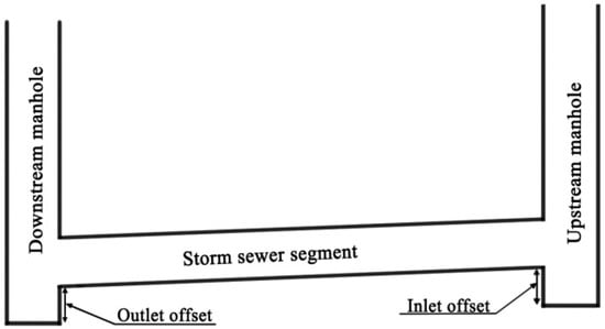
Figure 1.
Illustration of inlet and outlet offset.
The time series of flow rate, flow depth, and flow velocity of any pipe segment can be obtained through running SWMM hydrological and hydraulic simulation. If the maximum flow depth does not meet the constraint of maximum ratio of flow depth to pipe diameter, the original pipe diameter is updated to the diameter calculated with Manning’s equation based on the maximum flow rate and unchanged slope. If the velocity does not meet the maximum velocity and minimum velocity constraints, the original slope is updated to the slope calculated with Manning’s equation based on the maximum or minimum flow velocity and unchanged diameter. The specific process of the proposed algorithm will be discussed in detail later.
4. Model Development
This article presents a novel storm sewer design algorithm on the basis of the hydrological and hydraulic simulation in SWMM to determine pipe diameters and slopes. The design practice is concentrated on pipe diameters and slopes design for a sewer network with a given layout. The objective function of the storm sewer network design problem can be defined as:
Constraints:
- vmin < vi < vmax
- hmin < hi < hmax
- Di+1 > Di
- Hi > Hmin
where i refers to pipe i = 1,…, I (total number of pipes), Di (m) is the diameter of the i-th pipe, Hi (m) is the cover depth of the i-th node, vmin (m/s) and vmax (m/s) are the minimum and maximum velocity, respectively, hmin and hmax are the minimum and maximum ratio of flow depth to pipe diameter, respectively, and Hmin (m/s) is the minimum pipe cover depth. Storm hyetograph is counted in the hydrologic simulation each time the SWMM computation engine is run, and the peak flow is taken as designed discharge.
The design task is iteratively solved in two consecutive stages. In the first stage, starting with a set of initial values of pipe diameters, pipe cover depths, and manhole ground elevations, pipe cover depths are assumed to be fixed and pipe diameters are determined by a set of transition rules. In the second stage, the pipe cover depths are calculated by other transition rules with the pipe diameters obtained from the first stage assumed to be fixed. There are two criteria set for terminating the proposed automated algorithm: (a) A preset maximum number of iterations is achieved; (b) A behavior such that both flow depth and velocity meet the requirements is detected.
The design of a storm sewer network with a predefined layout involves the determination of the pipe diameter, pipe slope, and crown elevation. The major steps in executing this approach are presented below. The flowchart in Figure 2 shows the procedure.
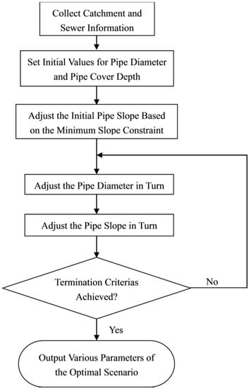
Figure 2.
Schematic description of the proposed algorithm based on Storm Water Management Model (SWMM).
Each parameter of the sewer network should be assigned an initial value before adjusting the pipe diameters and slopes, including manhole ground elevations, pipe diameters, pipe cover depths, as well as inlet and outlet offsets. It should be noted that the initial pipe diameter and pipe cover depth are the allowable minimum pipe diameter and average pipe cover depth, respectively.
4.1. Initial Value Computation
The initial pipe slope can be calculated according to the manhole ground elevation. From the upstream pipe segment to the downstream pipe segment, the pipe with a slope less than the minimum slope is adjusted successively. The specific transition rules are presented below:
- Pipe slope that is less than the minimum slope is increased to a minimum grade and the elevation of the pipe invert at the downstream, correspondingly, is decreased. After that, if the adjusted elevation of the pipe invert is less than the elevation of the manhole invert at the downstream, the elevation of the manhole invert and outlet offset at the downstream is updated, otherwise, only the outlet offset is updated.
- After adjusting the parameters of this pipe segment, if the adjusted elevation of the pipe invert is greater than the adjacent downstream pipe invert elevation at the upstream, only the outlet offset of the pipe segment is decreased. Otherwise, the adjacent downstream pipe crown elevation at the upstream node is kept the same as the pipe at the downstream node while the inlet offset and slope of the adjacent downstream pipe segment is updated.
4.2. First Stage Iteration
The flow rate, velocity, flow depth can be obtained by running SWMM computation engine. From the downstream pipe segment to the upstream pipe segment, the pipe with a maximum flow depth dissatisfying the constraint of maximum ratio of flow depth to pipe diameter are adjusted successively. The flowchart of the design procedure in the first stage is given in Figure 3. The main transition rules are given below:
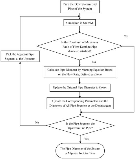
Figure 3.
Flowchart for the design process in the first stage.
- Based on the maximum flow rate obtained by the hydrological and hydraulic simulation, the required diameter is calculated using Manning’s equation. The calculated diameter is rounded to the upper discrete diameter available and the original pipe diameter is updated to this value.
- After adjusting the pipe diameter, if the original inlet and outlet offset is greater than the increase of the pipe diameter, the original inlet and outlet offset will be updated. The elevation of the manhole invert at the upstream and downstream is kept unchanged for the next step, otherwise, all the parameters will be updated correspondingly.
- After adjusting the parameters of this pipe segment, the inlet and outlet offset of the adjacent upstream and downstream pipe segment are updated.
- Every time after the adjustment of the pipe diameter, all the downstream pipe diameters are updated to ensure there is no decrease in sewer pipe diameter in the downstream direction.
4.3. Second Stage Iteration
After an adjustment of the pipe diameter of all pipes, run SWMM computation engine. Pipes with a velocity greater than the maximum velocity or less than the minimum velocity are adjusted in the order of from downstream to upstream. The flowchart in Figure 4 shows the design procedure in the second stage and the main transition rules are given below:
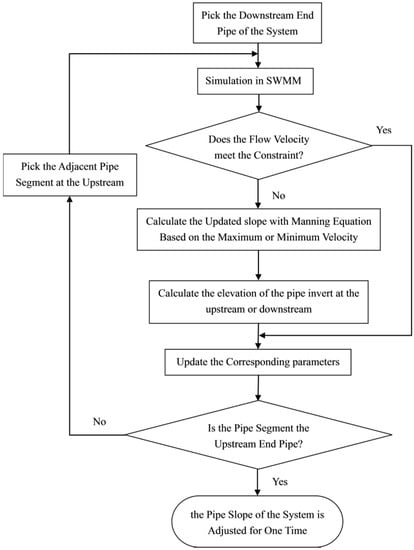
Figure 4.
Flowchart for the design process in the second stage.
- If the flow velocity is greater than maximum flow velocity, the slope of the pipe is decreased to the slope calculated by Manning’s equation based on maximum flow velocity. In the meanwhile, the elevation of the pipe invert at the upstream is decreased.
- After the elevation of the pipe invert at the upstream is decreased, if the adjusted elevation of the pipe invert is greater than the elevation of the manhole invert at the upstream, the inlet offset is updated and the elevation of the manhole invert at the upstream is kept unchanged for the next step. Otherwise, both parameters need to be updated and the outlet offset of the adjacent upstream pipe segment is updated simultaneously with the slope keeps unchanged.
- If the flow velocity is less than minimum flow velocity, the slope of the pipe is increased to the slope calculated by Manning’s equation based on minimum flow velocity constraint and the elevation of the pipe invert at the downstream is decreased correspondingly.
- After the elevation of the pipe invert at the downstream is decreased, if the adjusted elevation of the pipe invert is greater than the adjacent pipe invert elevation at the downstream, only the outlet offset of the pipe segment is decreased. Otherwise, the adjacent downstream pipe crown elevation at the upstream node is kept the same as the pipe at the downstream node while the inlet offset and slope of the adjacent downstream pipe segment is updated.
5. Model Applications
5.1. Description of Study Cases
In this section, the performance of the proposed automated algorithm based on SWMM is investigated by applying it in the design of a real urban sewer system (case 1) and a benchmark sewer network from the literature (case 2). The first case is employed to illustrate the feasibility of the proposed method in real-world practice. Results from the automated algorithm are compared with those generated by the conventional design procedure. The study area is a typical hilly city with significant terrain variations including reverse slope, gentle slope, and steep slope. This case is used to verify the performance of the proposed algorithm in a complex terrain condition. The storm sewer network consists of a main sewer line and six major branches, as shown in Figure 5a. The second case is a sewer system originally designed by Mays and Wenzel [12]. This sewer system composes 20 pipes and 21 manholes, as shown in Figure 5b. The proposed algorithm is applied to this case. The design result is compared with one of the existing optimal solutions—namely, adaptive Cellular Automata (CA) proposed by Afshar et al. [21].
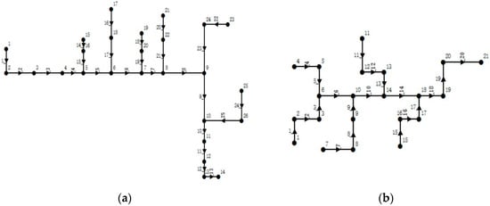
Figure 5.
Layouts of the two sewer networks: (a) layout for case 1; (b) layout for case 2.

Table 1.
Summary of basic storm sewer information in case 1.
Table 2.
Summary of basic storm sewer information in case 2.
5.2. Automated Design Procedure
In case 1, the data about the characteristics of catchment and storm sewer network with pre-determined layout in the study area were collected before constructing the model. In SWMM, Dynamic Wave routing was selected for the hydraulic simulation for its applicability to handle complex hydraulic conditions including reverse flow, backwater effects and pressurized flow etc. [2]. Chicago storm hyetograph was generated using local storm intensity formula with a return period of 4 years. The main steps in executing the proposed approach are presented below.
- Assign value for the manhole ground elevation according to the collected catchment information.
- Assign initial value for the properties of the sewer networks, pipe diameters and minimum pipe cover depths.
- Adjust the initial pipe slopes to satisfy the minimum slope constraint.
- Determine the pipe diameter and slope calculated iteratively with two consecutive stages.
Table 3 presents the design results of main storm sewer trunk line obtained from the proposed SWMM-based sewer network design method.
Table 3.
Comparison of the results for the proposed method and the conventional procedure.
In the conventional design process of a storm sewer system, the surface runoff entering the storm sewer system is calculated using the Rational method with a single composite runoff coefficient for the whole catchment. The Rational method is a lumped runoff calculation formula that could provide a design discharge with a minimum set of data required. But it ignores several key factors that impact the peak discharge such as surface storage declination of soil infiltration rate and varying rainfall intensity that occurs over time. The inflow is translated from the upstream end to the downstream end of the pipe, with no change in shape (i.e., steady flow routing) [2]. Then, Manning’s equation is adopted to describe the relation among flowrate, flow depth, and pipe slope to determine the final pipe diameter and slope.
The total storm sewer network costs need to be considered in the whole design process and the costs entail many factors, including the costs of material, excavation, transport, etc. The cost discussed here consists of the cost of the sewer pipes and the cost of manholes. Steele summarized the average cost of pipes ranging in diameter from 0.3 to 2.1 m and the cost of manholes with different depths [28]. However, it should be noted that the cost of a pipe network involves many factors, and the cost of the sewer network issue in this paper is simplified with no adverse effect on the quality of the proposed algorithm. Table 3 compares the design results obtained from the proposed SWMM-based sewer network design procedure and the conventional design method.
In case 2, Afshar adopted an adaptive refinement procedure to enhance the efficiency of the two-phase simulation optimization cellular automata (CA) for optimal design of a storm sewer system [29]. The kinematic wave routing was selected to describe the network hydraulic conditions at each CA iteration [29]. To be consistent, in the proposed algorithm, hydraulic simulation in SWMM is carried out with fixed design discharge into each manhole. The major steps in executing this approach are basically consistent with those described in case 1. Table 4 compares the design results obtained from the proposed SWMM-based sewer network design algorithm and the adaptive CA.
Table 4.
Comparison of the results for the proposed method and the Adaptive CA.
5.3. Discussion of Results
It can be observed from Table 3 that the diameters and slopes obtained by the proposed automated algorithm are similar to those calculated by the conventional design method. Discrepancies exist in the design of some pipe segments. Compared to the conventional design results, the larger size pipes in the proposed algorithm tend to have a smaller slope, while the slope of the pipe segment with smaller diameter is relatively larger. This is in accordance with the basic principles of the storm sewer system design, and indicates the proposed algorithm of sewer network design is reliable. Possibe reasons of these discrepancies are discussed below:
- In the conventional design procedure, flowrate calculation was carried out using Rational Method with a composite runoff coefficient. The hydraulic design was carried out based on manning equation and assuming a steady state open channel flow. The hydrologic and hydraulic processes occurring in the storm water system are greatly simplified in the conventional method. The proposed algorithm simulates a dynamic rainfall process and unsteady state flow which typically produce realistic hydrological and hydraulic results. This resulted a difference of the design discharge using the conventional process and the proposed algorithm. Hencefurther affects the designed pipe diameters and slopes.
- Except for pipe 1, the diameter of the remaining pipe segments obtained by the proposed algorithm are basically smaller than those by the conventional design method. This could be attributed to the nature of the proposed algorithm and the characteristics of the study area. The diameter of pipe 1 depends on the setting value of the initial pipe diameter. In the design process of the proposed algorithm, the pipe diameter with a minimum initial value increases gradually as the iteration progresses. The study area is steep and the pipe slope with large initial value decreases as the iteration progresses. The iteration terminates once the pipe flow velocity and depth meet the requirements. Therefore, while meeting the design requirements of the storm sewer system, a design scheme of storm sewer network with smaller diameter and pipe cover depth (i.e., a larger pipe slope) was obtained by the proposed algorithm.
Table 5 compares the total cost of the sewer system obtained by the conventional design procedure and by the proposed design approach. By using the proposed design approach, the total cost of the storm sewer network decreased from $1,057,551 to $961,703 with the total savings of over $95,848 or about 9% with lower cost of both pipes and manholes.
Table 5.
Optimal network cost obtained by different methods for the two cases.
Table 5 compares the total cost of the sewer system obtained by the conventional design procedure and by the proposed design approach. By using the proposed design approach, the total cost of the storm sewer network decreased from $1,057,551 to $961,703 with a total savings of over $95,848 or about 9% with lower cost of both pipes and manholes.
Table 5 also compares the number of iterations and corresponding construction costs of the network obtained by the proposed methodology to the adaptive CA. The results show that the proposed algorithm is capable of obtaining the optimal scheme with fewer iterations. The reasons are summarized as below: In the process of iteration in the proposed algorithm, a one-way approaching method is employed to obtain the optimal scheme. The pipe diameters increase gradually and the slopes increase or decrease gradually depending on the topography of the study area, until the best solution is achieved; Most studies on the optimization algorithms of sewer networks, including the adaptive CA, were aimed at further improving the efficiency of screening out the optimal scheme from a large number of schemes, which leads to higher computational costs, especially for large sewer networks. In the proposed algorithm, although the total cost of the network is not taken as the objective function and the construction costs of its design scheme is a little higher than what obtained by the adaptive CA, the principle of minimum construction costs is followed throughout the iterative process. Compared with the adaptive CA, the construction cost only increased by 1%, but the number of iterations reduced apparently by 95%, which means the proposed algorithm leads to near-optimal solution with much less computational cost than the adaptive CA. Normally, a less computationally costly program is more favored by design consultant companies and engineers because of the reduced labor cost.
6. Conclusions
A novel automated algorithm based on SWMM with two iterative loops was introduced for the optimal design of a storm sewer system with a given layout. The pipe diameter and pipe cover depth are the variables to be determined in the design process. Starting with a set of initial values of pipe diameters, pipe cover depths, and manhole ground elevations, the pipe diameters are determined from downstream to upstream assuming the pipe slopes to be fixed values in the first stage. Every time the pipe diameter is adjusted, the pipe flow rate, velocity, and flow depth are obtained by running SWMM hydrological and hydraulic simulation modules. The pipe with a maximum flow depth dissatisfying the constraint of maximum ratio of flow depth to pipe diameter is adjusted successively. The pipe diameter is updated to the diameter calculated by Manning’s equation based on the maximum flow rate, and increases gradually as the iteration progresses. In the second stage, the pipe slopes are calculated with the pipe diameters assumed to be fixed values. SWMM hydrological and hydraulic simulation modules are run, and the slope of the pipe with a velocity greater than the maximum velocity or less than the minimum velocity is adjusted using Manning’s equation from downstream to upstream. The process of adjusting the pipe diameters in the first stage and the pipe slopes in the second stage is iterated until the termination criterion is reached. The proposed algorithm was used to solve a real urban sewer system in a hilly city and a benchmark sewer network from the literature, and the results were presented and compared with the results obtained by the conventional design method and another optimal method. The proposed design method is proved to be reliable, more efficient, and well adapted to topographic changes.
Acknowledgments
The research reported here is supported by the National Key R&D Program of China, non-point source pollution control and stormwater management technology in hilly cities, the Ministry of Science and Technology, PR China (No. 2017YFC0404704).
Author Contributions
Zhiyu Shao developed the algorithm and performed the simulations. Xiaoyuan Zhang wrote part of the paper and prepared the figures for this paper. Shihu Deng and Shuang Li provided useful advice on the encoding process. Hongxiang Chai made some corrections.
Conflicts of Interest
The authors declare no conflict of interest.
References
- Kuichling, E. The relation between rainfall and the discharge of sewers in populous districts Trans. Am. Soc. Civ. Eng. 1889, 20, 1–56. [Google Scholar]
- Rossman, L.A. Storm Water Management Model User’s Manual (Version 5.1); U.S. Environmental Protection Agency: Cincinnati, OH, USA, 2015.
- Peng, H.Q.; Liu, Y.; Wang, H.W. Urban storm water forecasting model and drainage optimization based on water environmental capacity. Environ. Earth Sci. 2016, 75, 1–11. [Google Scholar] [CrossRef]
- Rossman, L.A. Storm Water Management Model Reference Manual Volume I—Hydrology (Revised); U.S. Environmental Protection Agency: Cincinnati, OH, USA, 2016.
- Deininger, R.A. Computer aided design of waste collection and treatment systems. In Proceedings of the 2nd Annual Conference of American Water Resources, Chicago, IL, USA, 18 May 1966; pp. 247–258. [Google Scholar]
- Holland, M.E. Computer Models of Wastewater Collection Systems. Ph.D. Thesis, Harvard University, Cambridge, MA, USA, 1966. [Google Scholar]
- Deininger, R.A. Systems Analysis for Water Supply and Pollution Control, Natural Resource Systems Models in Decision Making. 1970. Available online: http://scholar.google.com/scholar_lookup?title=Systems%20analysis%20for%20water%20supply%20and%20pollution%20control%2C%20natural%20resource%20systems%20models%20in%20decision%20making &author=RA.%20Deininger&publication_year=1970 (accessed on 28 September 2017).
- Dajani, J.S.; Hasit, Y. Capital cost minimization of drainage networks. J. Environ. Eng. Division 1974, 100, 325–337. [Google Scholar]
- Price, R.K. Design of storm water sewers for minimum construction cost. In Proceedings of the 1st International Conference on Urban Storm Drainage, Southampton, UK, January 1978; pp. 636–647. [Google Scholar]
- Kulkarni, V.S.; Khanna, P. Pumped wastewater collection systems optimization. J. Environ. Eng. 1985, 111, 589–601. [Google Scholar] [CrossRef]
- Miles, S.W.; Heaney, J.P. Better than optimal method for designing drainage systems. J. Water Resour. Plan. Manag. 1988, 114, 477–499. [Google Scholar] [CrossRef]
- Mays, L.W.; Wenzel, H.G. Optimal design of multi-level branching sewer systems. Water Resour. Res. 1976, 12, 913–917. [Google Scholar] [CrossRef]
- Walters, G.A.; Lohbeck, T. Optimal layout of tree networks using genetic algorithms. Eng. Optim. 1993, 22, 27–48. [Google Scholar] [CrossRef]
- Heaney, J.P.; Pitt, R.; Field, R. Innovative Urban Wet-Weather Flow Management Systems; EPA/600/R-99/029; U.S. Environmental Protection Agency: Cincinnati, OH, USA, 2000.
- Afshar, M.H. Application of a genetic algorithm to storm sewer network optimization. Sci. Iran. 2006, 13, 234–244. [Google Scholar]
- Pan, T.C.; Kao, J.J. GA-QP model to optimize sewer system design. J. Environ. Eng. 2009, 135, 17–24. [Google Scholar] [CrossRef]
- Haghighi, A.; Bakhshipour, A.E. Optimization of sewer networks using an adaptive genetic algorithm. Water Resour. Manag. 2012, 26, 3441–3456. [Google Scholar] [CrossRef]
- Guo, Y.; Walters, G.A.; Khu, S.T.; Keedwell, E. A novel cellular automata based approach to storm sewer design. Eng. Optim. 2007, 39, 345–364. [Google Scholar] [CrossRef]
- Afshar, M.H.; Shahidi, M.; Rohani, M. Application of cellular automata to sewer network optimization problems. Sci. Iran. 2011, 18, 304–312. [Google Scholar] [CrossRef]
- Afshar, M.H.; Rohani, M. Optimal design of sewer networks using cellular automata-based hybrid methods: Discrete and continuous approaches. Eng. Optim. 2012, 44, 1–22. [Google Scholar] [CrossRef]
- Afshar, M.H.; Zaheri, M.M.; Kim, J.H. Improving the efficiency of Cellular Automata for sewer network design optimization problems using Adaptive Refinement. Proc. Eng. 2016, 154, 1439–1447. [Google Scholar] [CrossRef]
- Afshar, M.H. Improving the efficiency of ant algorithms using adaptive refinement: Application to stormwater network design. Adv. Water Resour. 2006, 29, 1371–1382. [Google Scholar] [CrossRef]
- Afshar, M.H.; Moeini, R. Partially and fully constrained ant algorithms for the optimal solution of large scale reservoir operation problems. J. Water Resour. Manag. 2008, 22, 1835–1857. [Google Scholar] [CrossRef]
- Afshar, M.H. A parameter free continuous Ant colony optimization algorithm for the optimal design of storm sewer networks. Adv. Eng. Softw. 2010, 41, 188–195. [Google Scholar] [CrossRef]
- Moeini, R.; Afshar, M.H. Constrained Ant Colony Optimisation Algorithm for the layout and size optimisation of sanitary sewer networks. Urban Water J. 2012, 10, 1–20. [Google Scholar] [CrossRef]
- Afshar, M.H. Rebirthing particle swarm optimization algorithm: Application to Storm Sewer Network design. Can. J. Civ. Eng. 2008, 35, 1120–1127. [Google Scholar] [CrossRef]
- Karovic, O.; Mays, L.W. Sewer system design using simulated annealing in excel. Water Resour. Manag. 2014, 28, 4551–4565. [Google Scholar] [CrossRef]
- Steele, J.C.; Mahoney, K.; Karovic, O. Heuristic Optimization Model for the Optimal Layout and Pipe Design of Sewer Systems. Water Resour. Manag. 2016, 30, 1605–1620. [Google Scholar] [CrossRef]
- Walters, G.A. A review of pipe network optimization techniques. In Pipeline Systems, Fluid Mechanics and Its Applications; Coulbeck, B., Evans, E., Eds.; Springer Science & Business Media: Dordrecht, The Netherlands, 1992; pp. 3–13. [Google Scholar]
- Liong, S.Y.; Chan, W.T.; ShreeRam, J. Peak-flow forecasting with genetic algorithm and SWMM. J. Hydraul. Eng. 1995, 121, 613–617. [Google Scholar] [CrossRef]
- Krebs, G.; Kokkonen, T.; Valtanen, M.; Koivusalo, H.; Setälä, H. A high resolution application of a stormwater management model (SWMM) using genetic parameter optimization. Urban Water J. 2013, 10, 394–410. [Google Scholar] [CrossRef]
- Martinez-Solano, F.J.; Iglesias-Rey, P.L.; Saldarriaga, J.G.; Vallejo, D. Creation of an SWMM Toolkit for Its Application in Urban Drainage Networks Optimization. Water 2016, 8, 259. [Google Scholar] [CrossRef]
- Wang, K.H.; Altunkaynak, A. Comparative case study of rainfall-runoff modeling between SWMM and fuzzy logic approach. J. Hydrol. Eng. 2011, 17, 283–291. [Google Scholar] [CrossRef]
- Granata, F.; Gargano, R.; Marinis, G. Support vector regression for rainfall-runoff modeling in urban drainage: A comparison with the EPA’s storm water management model. Water 2016, 8, 69. [Google Scholar] [CrossRef]
© 2017 by the authors. Licensee MDPI, Basel, Switzerland. This article is an open access article distributed under the terms and conditions of the Creative Commons Attribution (CC BY) license (http://creativecommons.org/licenses/by/4.0/).