Abstract
The management of a water distribution network (WDN) is performed by valve and pump control, to regulate both the pressure and the discharge between certain limits. The energy that is usually merely dissipated by valves can instead be converted and used to partially supply the pumping stations. Pumps used as turbines (PAT) can be used in order to both reduce pressure and recover energy, with proven economic benefits. The direct coupling of the PAT shaft with the pump shaft in a PAT-pump turbocharger (P&P plant) allows us to transfer energy from the pressure control system to the pumping system without any electrical device. Based on experimental PAT and pump performance curves, P&P equations are given and P&P working conditions are simulated with reference to the operating conditions of a real water supply network. The annual energy saving demonstrates the economic relevance of the P&P plant.
1. Introduction
The sustainable management of the water supply is becoming a major challenge within the framework of the water–energy–food nexus [1,2]. A reduction in water leakage and an efficient use of energy are considered essential in order to contain greenhouse gas emissions and to limit the impacts of climate change [3,4,5]. In the last few years, a number of research papers in literature have focused on new methodologies for the efficient management of a WDN [6]. Mini hydro power plants are a common practice in water transmission lines [7,8], where a stable discharge and pressure drop are present and can be exploited to produce energy. Pressure reducing valves (PRV) were first proposed to obtain optimal pressure values in water distribution lines, with the benefit of reducing the amount of water leakage [9,10]. Several methods for the optimal location of PRVs have been developed [11,12]. Recently, the substitution of PRVs with micro hydro power plants has been proposed [13,14,15]. In the presence of pumping systems, the strategy for energy cost savings and energy efficiency could be based on the increase in the hydraulic efficiency of the pumps and the electrical efficiency of motors; on the introduction of performance standards to which the pumps on the market must comply; on the use of variable frequency drivers to increase the efficiency performance of pumping groups working in variable conditions; and on the energetic assessment of energy use in the network [16,17].
Compensation tanks, which fix the pressure in a particular water district, are commonly inserted between water transmission and water distribution systems. At the tank intake, a residual pressure of the flow can be present and it is usually merely dissipated by a valve. In the presence of a large variability of ground elevation between the parts of the system, a second tank positioned at a higher elevation may be necessary in order to guarantee sufficient pressure to the users of this higher district. The hydraulic energy dissipated at the lower tank could be comparable with the energy to be supplied to the pump to deliver water to the higher tank. Therefore, a turbine could be placed at the tank inflow in order to both reduce pressure and recover energy to supply the pump. Three main problems limit the convenience of the installation of a turbine governed generator to power the pumping system, namely (i) the small amount of power available; (ii) the high cost of traditional turbines; and (iii) the low combined efficiency of the two electromechanical devices (the turbine generator and the pump motor) [18,19,20]. PATs could be employed instead of classic turbines, since they are considered a viable and flexible solution for energy production in a WDN, due to their lower cost and their generally acceptable efficiency [21,22,23,24]. In order to reduce the investment cost and increase the efficiency of the system, the PAT and a pump can be directly coupled and mounted on the same shaft without any intermediate generator or motor. The resulting PAT-pump turbocharger should be a viable solution. However, an appropriate P&P theory for water systems has, to the best of the authors’ knowledge, not yet been developed. The main difficulty in the design of such a device derives from the variability of the rotational speed. While an asynchronous generator defines the rotational speed of the turbine, according to the electric grid frequency, the rotational speed of a turbocharger is unknown and influences the hydraulic behaviour of the whole system. In this paper, a complete P&P formulation is developed, and a complete mathematical model is given for the design of the P&P plant when the boundary conditions are assigned. In addition, a non-dimensional solution is presented to discuss the general behaviour of the P&P plant. The solutions show that the performance of the system depends on the number of stages of both the pump and the PAT and on the pump–PAT discharge ratio. Furthermore, the model has been applied to four different scenarios based on the experimental discharge pattern of a pressure control station in a water distribution network in southern Italy. The results are investigated in terms of pressure reduction and pumping discharge and head, to show the hydraulic potential of the P&P device. The annual energy saving is also calculated for each scenario.
2. State-of-the-Art
2.1. Machine Behaviour
Experimental tests can provide the performance curves of a pump or a PAT at a certain rotational speed value or, alternatively, CFD techniques can be employed. Such curves express the relations of head (H), mechanical power (P) and efficiency (η) with the discharge (Q), and can be expressed as follows:
Usually, a quadratic polynomial can be successfully used to fit the head data, while a cubic polynomial best explains the power data. The efficiency curve presents a maximum value for the discharge. The working point (, , , ) is called the best efficiency point (BEP). Affinity laws can be used to calculate the performance of two similar machines, having and diameters, respectively, and rotating at different speeds. The performances of two homologous working points, (, , ) and (, , ), respectively, are related to both the ratios of the respective speeds, and , and the scale ratios, , as follows:
The Equation (2) is generally used by pump manufacturers to predict the behaviour of their machines for different rotational speeds, even if some studies demonstrate that Equation (2) does not predict the real behaviour of turbomachines with a high accuracy in the whole range of rotational speeds [25,26]. Principally, according to affinity laws, the efficiency value of two homologous points is constant with speed. However, this result is not in agreement with the real behaviour of pumps. Simpson and Marchi [27] showed that the efficiency value at the BEP is attained only at a given optimal speed value, while a decrease is observed as the speed diverges. Furthermore, a recent experimental study [28] on the behaviour of PATs has demonstrated that the use of affinity laws could lead to significant errors in the prediction of machine performance, up to in the prediction of head and in the prediction of efficiency. The authors proposed a new semi-theoretical model for semi axial machines for a better prediction of characteristic PAT performance curves. was identified experimentally and related to geometrical pump parameters. Then, the BEP at a rotational speed could be related to the BEP at by a relaxation of the affinity equations (RAE):
By experimental estimation of the functions , and [28], a better agreement was found between the theoretical and experimental characteristic curves with a significant reduction in the prediction error.
2.2. Energy Recovery in Water Systems
Hydropower production in a water supply system is a viable option where the available hydraulic power is fairly large and constant, with a great economic benefit and a small environmental impact. Examples of such scenarios are found along water transmission lines, from the water source to the distribution centre, where several small hydropower projects are already active [29]. Hydropower plants could also be used in water distribution networks, as a replacement of a PRV. Nevertheless, such a plant would face a large variability of both discharge and head, due to the hourly variability of water users’ demand, as well as the small amounts of available power [30,31]. Furthermore, the turbine head curve exhibits a behaviour which is completely different from the head drop curve of a regulating valve: the former increases with the discharge, while the latter decreases as the flow rate increases [32]. All these difficulties, together with the small amount of power available, hinder the use of classic turbines, due to their high price and their long payback period. Some studies demonstrate that the use of PATs, instead of classic turbines, to substitute the dissipation valves could be a convenient practice even if the available power is low, due to the low price and the mechanical simplicity of such devices [33]. Several studies have shown that the best efficiency of a PAT could be greater than 70% [21,22,23]. Ramos et al. [34] showed that the cost of a PAT is much smaller if compared with the cost of a classic turbine, with unit costs ranging between 200 €/ and 400 €/, where the turbine cost ranges between 300 €/ and 800 €/. Carravetta et al. [35] showed that the payback period of a PAT energy recovery system could be really short, ranging between 6 months and 3 years, while Fecarotta et al. [36] showed that the coupling of the pressure control strategy with an energy recovery strategy within a water network could be convenient if the valves are replaced by PATs, with high 10 year net present values. Other studies propose different solutions for the regulation of the PAT plant to address the large variability of hydraulic characteristics and to match the turbine head and discharge with the needs of the network. Carravetta et al. [37] propose regulating the PAT either by a hydraulic or electric regulation system. In the former case, two hydraulic valves are placed in a series–parallel circuit to dissipate the excess head when the turbine head is too low or bypasses a part of the discharge when the flow rate is high. In the latter case, an electronic speed driver adjusts the rotational speed of the PAT to modify its performance. In 2014 , Carravetta et al. [38] compared the effectiveness of the different installation schemes of a PAT plant. Other preliminary studies have included an analysis of the optimal location of a PAT within a WDN [36,39,40] to maximize the power production.
3. Pump and PAT Characteristic Curves
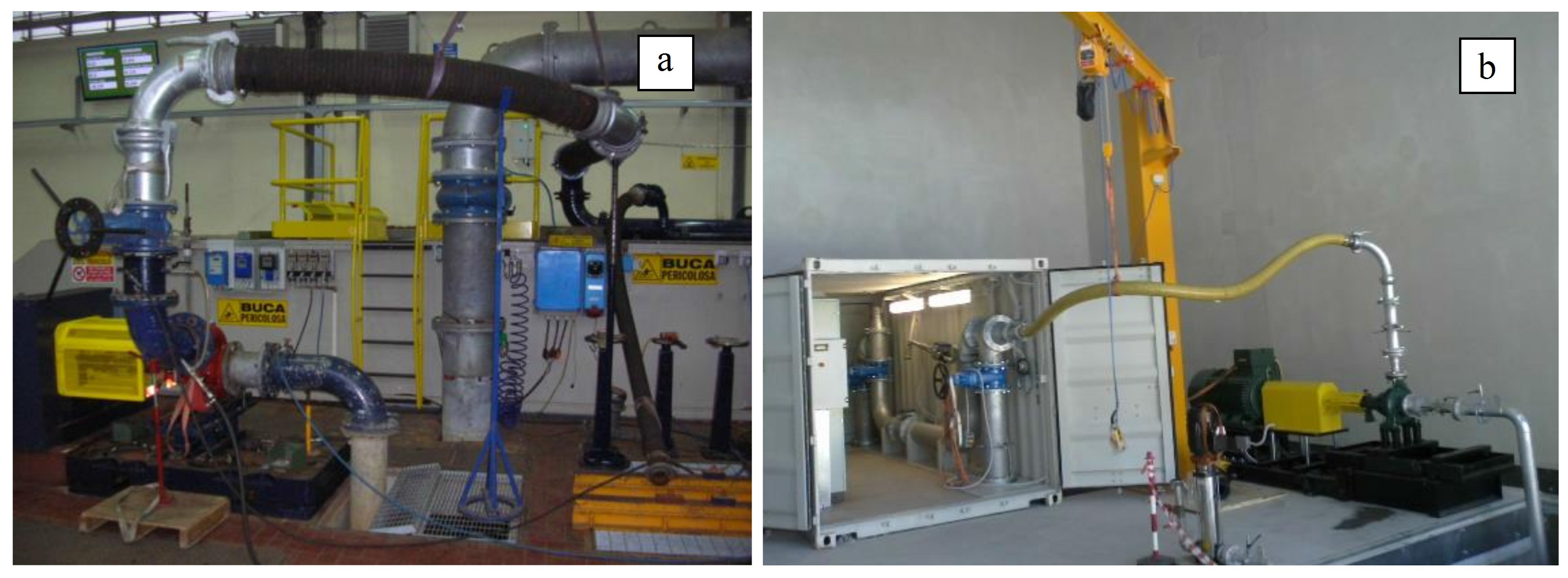
Experiments were performed in the Hydro Energy Laboratory (HELab) of the CESMA—University of Naples Federico II and in the qualification laboratory of Caprari Pumps Ltd. (Peterborough, UK). Pictures of the two laboratories are shown in Figure 1.
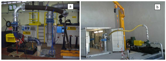
Figure 1.
Pictures of the qualification laboratory of Caprari ltd (a); and of HELab of University of Naples (b).
Both laboratories are equipped with digital magnetic flow meters, piezometric pressure transducers and digital power meters. A fixed level water tank is located below ground level to feed the hydraulic circuit and receive the circulated water. A gate valve is used to regulate the flow. The testing conditions in both laboratories comply with ISO 9906 (Rotodynamic pumps—Hydraulic performance acceptance test) level 1, IEC 60034-2-1 (Rotating electrical machines) and EN 50598-2 (Efficiency classes of converters and drive systems). The maximum measurement uncertainties are reported in Table 1.

Table 1.
Maximum measurement device uncertainties.
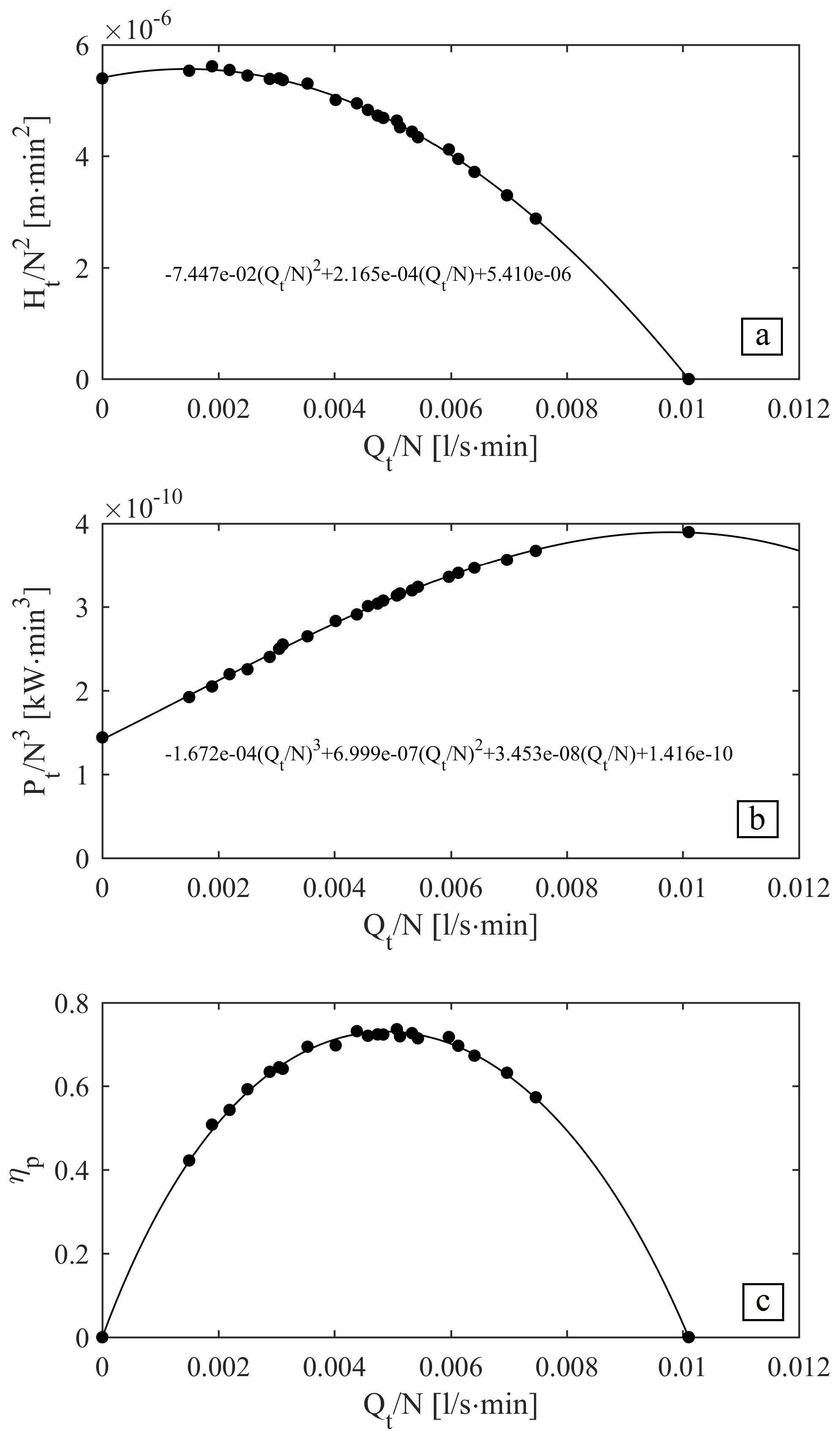
A two-stage pump unit, the Caprari model HMU, has been tested in the HELab. The specifications of the pump are reported in Table 2.

Table 2.
Specification of the Caprari HMU pump, as tested in HELab.
The working conditions for different rotation speeds have been tested and the main hydraulic and electric parameters have been measured. Head and power curves have been determined experimentally. Test results in the normalized parameter are shown in Figure 2.
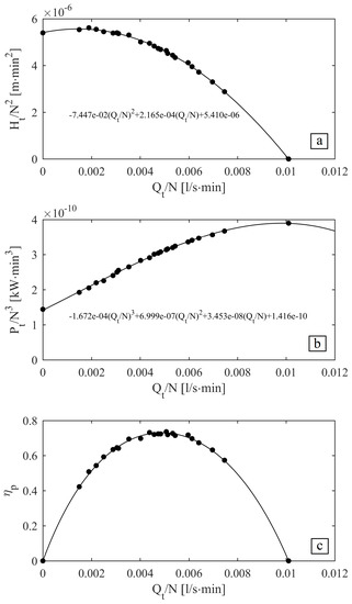
Figure 2.
Experimental normalized head (a), power (b) and efficiency (c) of the HMU pump and regression curves.
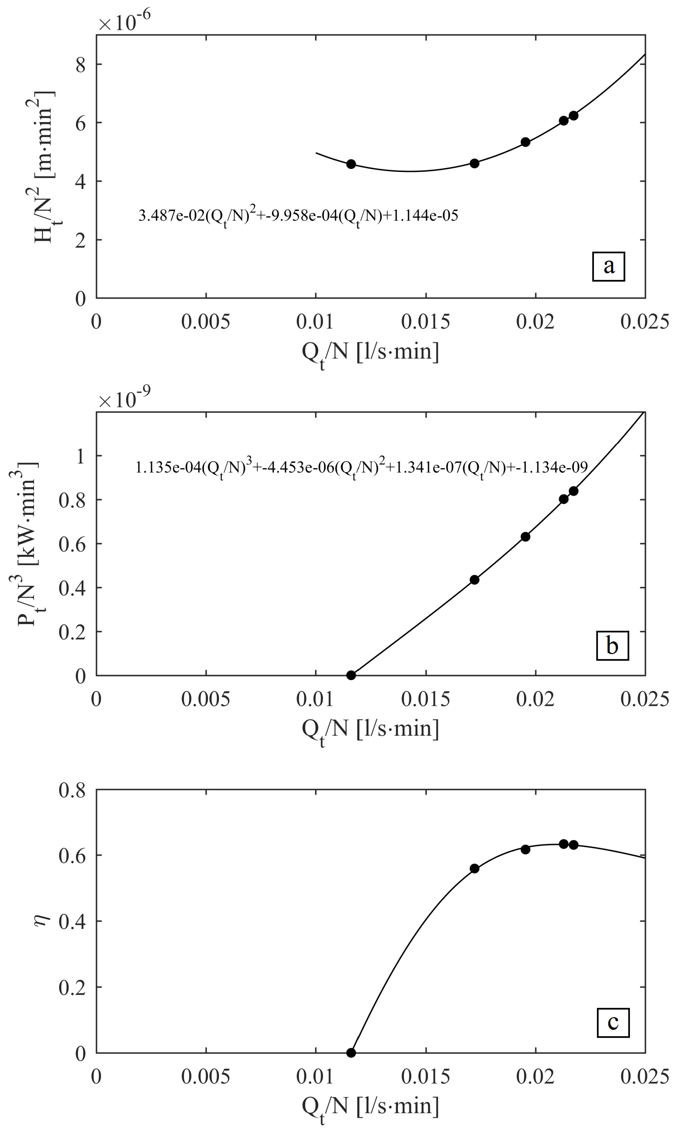
Another pump, the Caprari model NC80, has been tested in inverse mode in the Caprari qualification laboratory. The head and efficiency as determined experimentally are shown in the normalized plot of Figure 3, while the specifications are reported in Table 3.
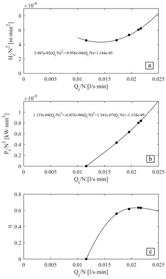
Figure 3.
Experimental normalized head (a), power (b) and efficiency (c) of NC80 PAT and regression curves.

Table 3.
Specification of Caprari NC80 PAT, as tested in Caprari laboratory.
4. PAT and Pump System (P&P) Modelling
In the design of a pumping system or a hydro power plant, the rotational speed of the device is imposed by the grid frequency or by a variable frequency driver. Instead, in a P&P, the group is free to achieve any rotational speed. The PAT provides the power for the pump and the rotational speed is set by the combination of the performance curves of the two devices with the network characteristics.
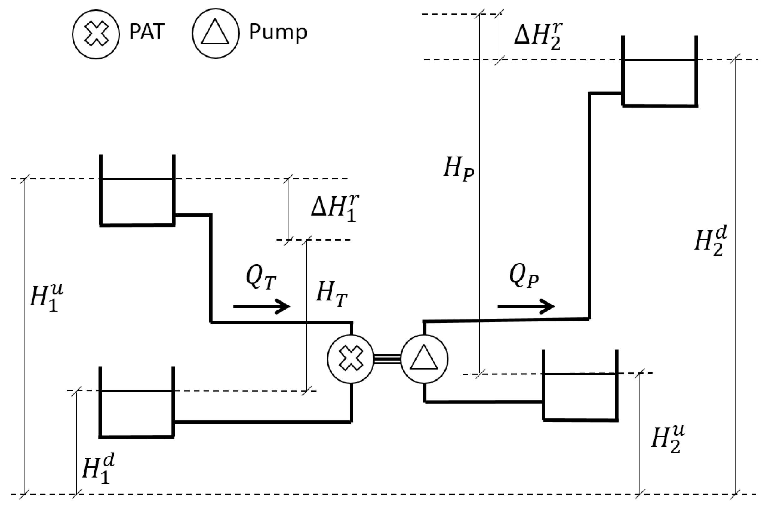
Figure 4 shows a simplified scheme of a P&P plant. The whole water supply system can be considered as two separated network districts which are connected by the P&P plant. The residual head at the end of district 1 that can be turbined within the PAT is represented by the difference , where is the head measured at the end point of district 1, is the head loss in the pipeline approaching the PAT and is the head downstream of the PAT. The lengths of the pipelines are not representative of the real system and, if the values of and are measured near the P&P system, the head losses and can be neglected. As a general case, the two values and are considered different, but the outlet tank of the PAT and the inlet tank of the pump are often the same. The presence of four tanks, however, could even be unnecessary if the P&P system is inserted in a fully pressurized network, and the values of the four variables, , , and depend on time according to the network behaviour. is the flow rate available at the PAT inlet. The power produced by the PAT is , being the PAT efficiency. Such power is transmitted to the pump by the shaft which connects the two machines. is the pumped flow rate while the total head required at the pump outlet is , where the meaning of the symbols is evident. The efficiency of the plant can be calculated as the ratio between the output hydraulic power at pump side and the input hydraulic power at PAT side. Thus, the plant efficiency η can be calculated as:
being the efficiency of the pump. If such a simplified scheme is used to model the water system, the design problem is defined by the following equations:
in the seven variables , , , , , and N, and being the mechanical power of the PAT and pump respectively, and the number of stages of the PAT and pump respectively and , , , , , , , , , , , , , and the experimental regression coefficients of the head curve and the power curve of the PAT and pump, respectively. A P&P node in the water system is described by the last five equations of Equation (5). The energy equations at the PAT intake and pump outlet balance the number of unknowns and equations. More generally, along the pipeline of the two districts, derivations, dissipation points, or additional supply points could be present. In this case, the design of the P&P plant is linked to the operating conditions of the two networks and the complexity of the design solution is connected to the complexity of the water system.
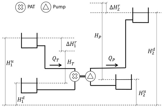
Figure 4.
Simplified scheme of the P&P plant.
Behaviour of the P&P Plant
The last five equations of Equation (5) can be rewritten if , , and :
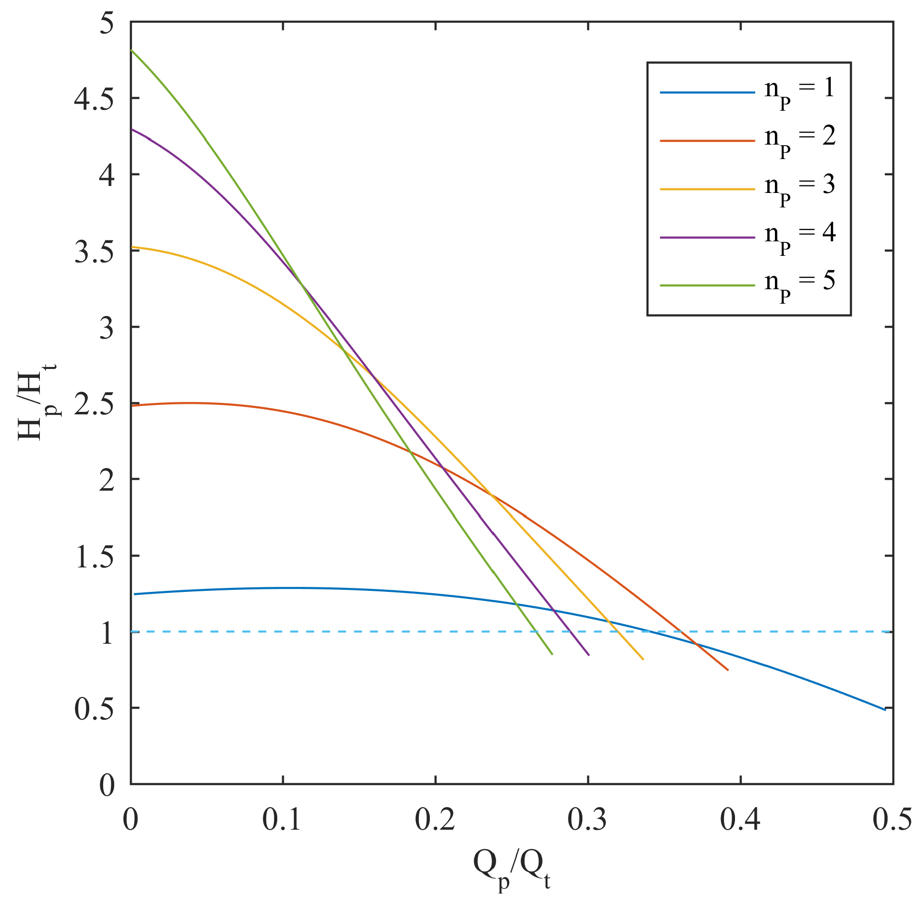
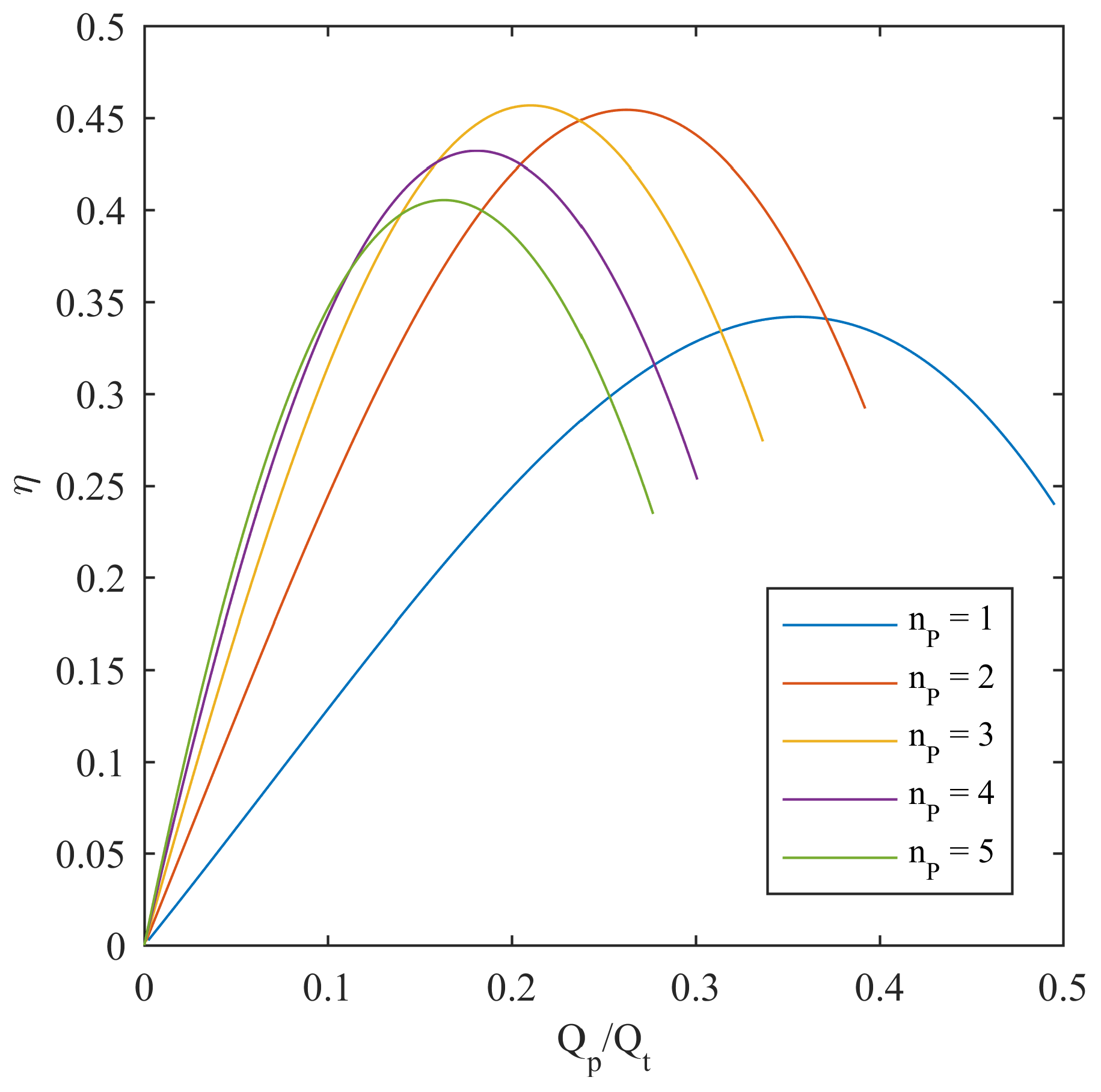
Equation (6) expresses the relationship between the four quantities , , and . A single curve relating and can be obtained if the number of stages of the pump and PAT are assigned. Because and , Equation (6) shows that the relationship between the ratio of the delivered discharge and the ratio of the delivered head is independent of the rotational speed. In Figure 5, the values of are plotted versus for the 1 to 5 pump stages with . In Figure 6, the plant efficiency η is plotted versus . The P&P working conditions are different depending on the number of pump stages. In the presence of a single stage, the pump head is slightly greater than the available head drop at the PAT and the flow rate ratio ranges between 0 and . With two pump stages, the pump head significantly increases (about times the head drop in the flow range 0–0.15) and also the range of flow rate ratio is larger (up to ). With an increasing number of pump stages, the range of flow rate ratio decreases (up to with five stages), while the head ratio increases (up to with five stages). The efficiency of the P&P system also depends on the number of stages. The lowest efficiency occurs for a single stage pump, when the P&P efficiency reaches its maximum value out of the range of the flow rate ratio. The efficiency significantly increases (from less than up to more than ) for a higher number of pump stages. Considering a P&P efficiency larger than , the range of working conditions that can be obtained with the selected pump is quite variable: up to of the water coming from district 1 can be pumped into district 2 with a increase in the pressure head, using a double stage pump, or, at the opposite extreme, with a four stage pump, of the water coming from district 1 can be pumped into district 2 with a pressure head being three times larger than the residual head of district 1. The best efficiency occurs for a three stage pump where of the incoming discharge can be pumped with a increase in head.
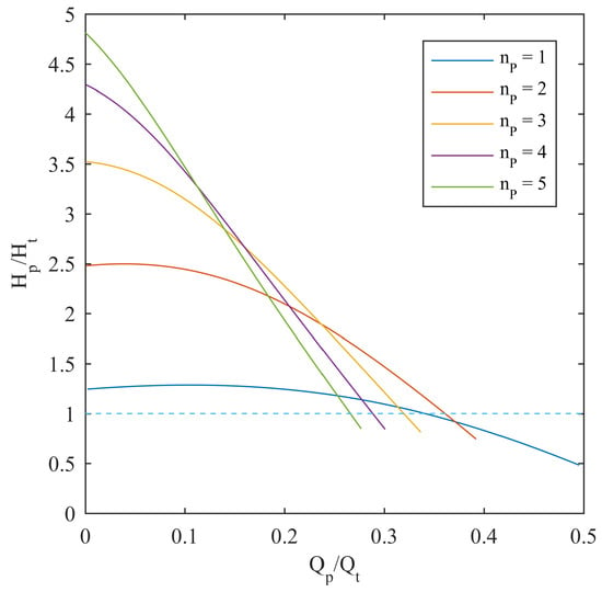
Figure 5.
Head ratio of the P&P plant for different numbers of pump stages with .
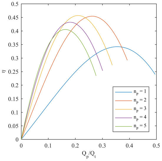
Figure 6.
Efficiency of the P&P plant for different pump stages with .
5. Case Study
The operating conditions in district 1 exhibit a daily pattern determined by the variation in user demand. Therefore, the and values depend on both the time and system configuration. The operating conditions in district 2 could be similar to those of district 1 if direct pumping in the network is provided. More frequently, the pumping station supplies water to an elevated tank, with fairly constant values of both and . As a case study, a simplified system is analyzed. The discharge approaching the PAT is imposed and the head losses along the pipe downstream of the pumping station are completely neglected. Two different supply conditions have been considered for the feeding of district 2:
- Elevated tank—Variable , constant
- Direct pumping—Variable , constant
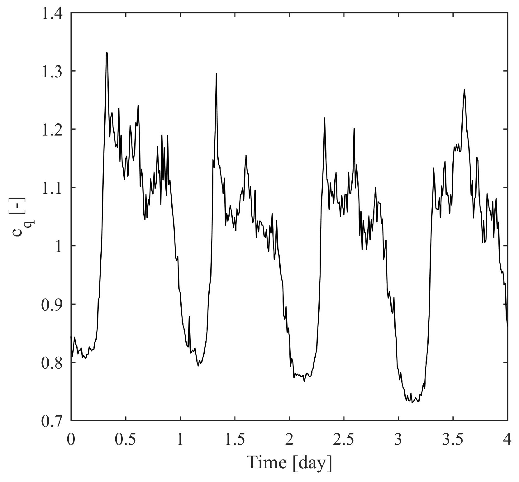
Equation (6) has been solved in order to find the three unknowns (, , N for scenario 1 and , , N for scenario 2). The daily pattern of a measuring station of the urban water distribution system of Pompei (Campania—Italy) has been scaled to obtain the approaching discharge . Figure 7 shows the non-dimensional 4 days pattern of flow rate , i.e., the instantaneous discharge , scaled with the average discharge. For both supply condition, two cases have been considered:
- (a)
- A high difference in ground elevation between district 1 and district 2 and large turbined discharge
- (b)
- A low difference in ground elevation between district 1 and district 2 and small turbined discharge
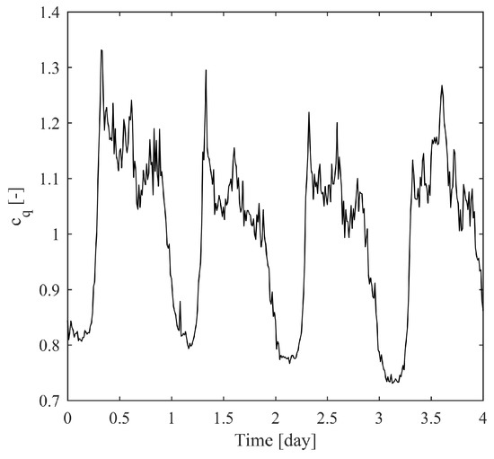
Figure 7.
Discharge pattern.
The average turbined discharge, (), is 40 in case a and 25 in case b. In the scenarios and the value of is assigned and set to 50 m in case a and 15 m in case b. In the scenarios and , the pumped discharge is assigned and equal to in case a and in case b. The first case corresponds to a four stage pump, allowing a maximum flow rate in district 2 equal to about with the head being maximum. In the second case, a two stage pump is considered, allowing a maximum flow rate in district 2 equal to about with the head being maximum. Table 4 shows the configuration of the four different scenarios.

Table 4.
Presentation of the different scenarios.
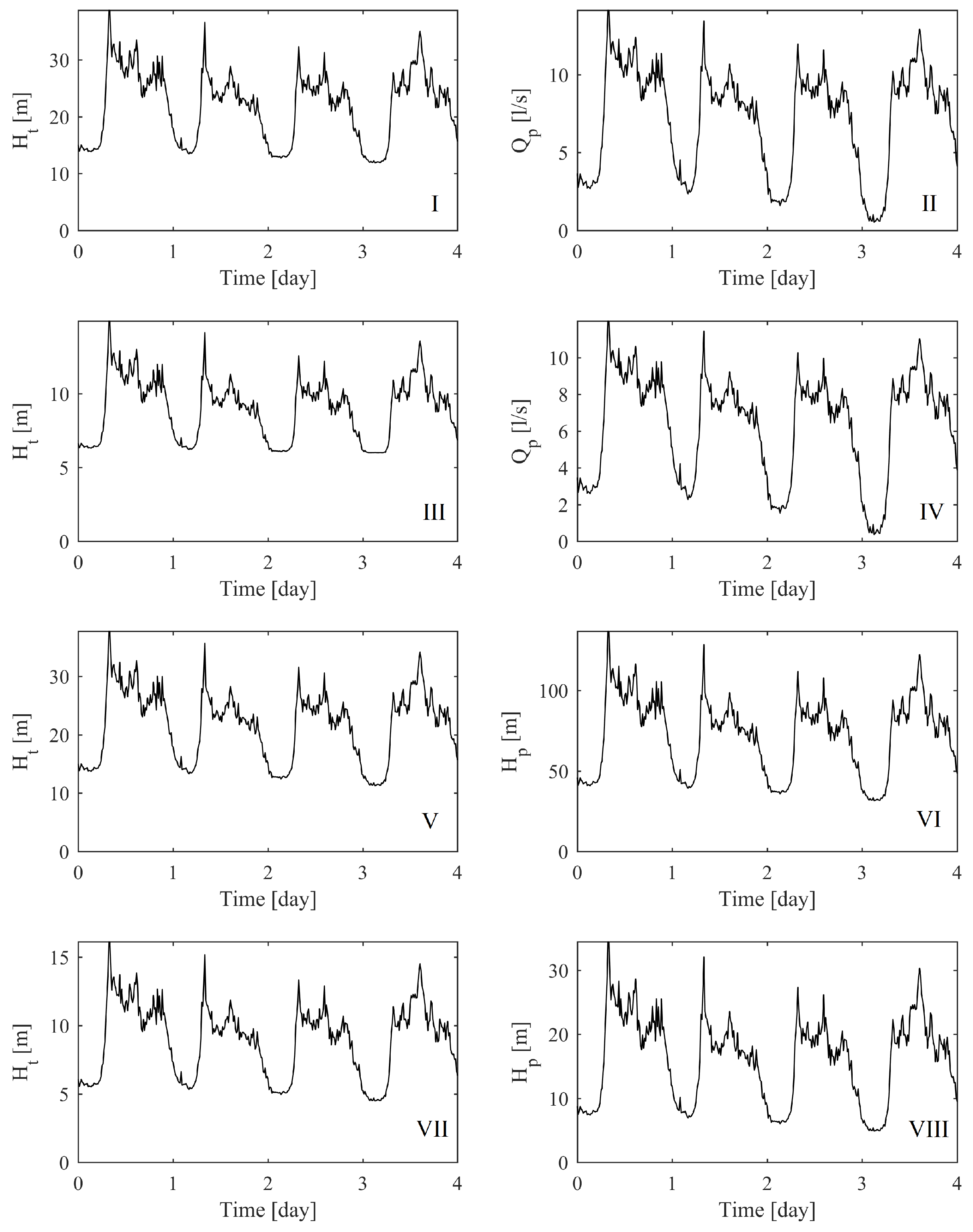
In Figure 8, the turbined head is shown for the four scenarios, as well as the pumped head for scenarios and and the pumped flow rate for scenarios and . The results show the performance of the P&P system in the assigned conditions specified in Table 4. Figure 8I,III,V,VII shows the values of the turbined head depending on time. The calculated values of should be less than the available residual pressure while an additional valve could be placed to dissipate the excess head, if necessary. When the pumping head is fixed (scenarios 1a and 1b) the pumped discharge is variable, according to Equation (5), as shown by Figure 8II,IV. If the average values of comply with the needs of district 2, the elevated tank could compensate for the variable discharge. Otherwise, the district should be provided with a second pumping system to supply the missing discharge. Figure 8VI,VIII shows the pumped head when the pumped discharge is fixed. Such a scenario can happen, for example, when a direct pumping is performed and the district is provided with an end-line tank to receive the excess discharge or feed the network during the high demand hours. In such a case, the pumped pressure should be contained within a certain range: a minimum pressure should be guaranteed by the pump to supply the end users, and a maximum value should not be exceeded to avoid any structural or leakage problems. When the average turbined discharge is higher (scenario 2a), Figure 8VI shows that the pumped head is always higher than 40 m and can also exceed 130 m in certain moments. In such a case, a dissipation valve could be placed to reduce the head when the pressure exceeds the upper limit. Instead, when the turbine discharge is lower (scenario 2b), the pumped head is always lower than 40 m and its minimum value is lower than 10 m. In this last case, if the minimum pressure is not guaranteed, a second ordinary pump can be installed to increase the pressure when necessary.
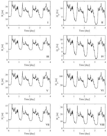
Figure 8.
Behaviour of the P&P system for scenario (I,II); (III,IV); (V,VI); and (VII,VIII).
Table 5 shows the values of the hydraulic power involved in the turbining and in the pumping at the P&P station. Both the average and the maximum values demonstrate that the power values of case a are higher than case b. Scenario corresponds to the highest power values while scenario exhibits the lowest power. The ratio between the average pumped power and the average turbined power represents the average efficiency of the P&P station. It can be considered satisfactory in all the four cases, since it is quite close to the maximum values of Figure 6. The last column of Table 5 shows the annual energy saving range, considering an average efficiency of the pumping group ranging between and . Such a saving is always relevant and it is obviously larger in scenarios and , where the pumped power is larger.

Table 5.
Hydraulic power values of the different scenarios.
6. Conclusions
A new P&P technology, coupling a PAT and a pump, has been studied on the basis of the experimental data of the pump working in direct or in inverse mode. A P&P is suitable in all cases when a certain amount of the water at the end of a water supply system, presenting a residual energy, has to be pumped to a second network at a higher pressure level. In such a case, P&P is a low cost technology allowing the recovery of the residual energy of the water in the first network and the increase of the pressure level of the water in the second network. Equations for P&P design have been presented, allowing a simple analysis of the P&P working conditions. Depending on the number of stages of the pumping, different operating conditions in the ancillary supply network can be obtained, in terms of water demand and pressure level. For the pump model used in the simulation, up to of the water can be transmitted by the P&P to a pressure level higher than the initial level. If the water to be transmitted is limited to , the pressure level can be increased by the P&P by more than three times. This high potentiality is determined by the total efficiency of the P&P, even greater than . The case study shows the viability of the system in different scenarios, considering different supply conditions as well as different values of turbined discharge. The results, depending on the network configuration and the considered scenario, show that the P&P system can completely replace an ordinary pumping system or supply the network when the available hydraulic power is high. The calculated annual energy saving demonstrates the economic relevance of the P&P plant. As a future implementation of this study, an experimental investigation on a laboratory prototype could be undertaken and the results would be used for the design of a full scale plant, to investigate the interactions with a WDN in a real situation.
Author Contributions
Lauro Antipodi and Oreste Fecarotta performed the experiments on the PAT and on the pump. Armando Carravetta, Oreste Fecarotta and Umberto Golia developed the mathematical model. Umberto Golia ran the simulations. Armando Carravetta and Oreste Fecarotta wrote the paper.
Conflicts of Interest
The authors declare no conflict of interest.
References
- Pahl-Wostl, C. Transitions towards adaptive management of water facing climate and global change. Water Resour. Manag. 2007, 21, 49–62. [Google Scholar] [CrossRef]
- Ramos, H.; Covas, D.; Araujo, L.; Mello, M. Available energy assessment in water supply systems. In Proceedings of the XXXI IAHR Congress, Seoul, Korea, 11–16 September 2005.
- Gallagher, J.; Styles, D.; McNabola, A.; Williams, A.P. Life cycle environmental balance and greenhouse gas mitigation potential of micro-hydropower energy recovery in the water industry. J. Clean. Prod. 2015, 99, 152–159. [Google Scholar] [CrossRef]
- Almandoz, J.; Cabrera, E.; Arregui, F.; Cabrera, E.; Cobacho, R. Leakage Assessment through Water Distribution Network Simulation. J. Water Resour. Plan. Manag. 2005, 131, 458–466. [Google Scholar] [CrossRef]
- Xue, X.; Hawkins, T.R.; Schoen, M.E.; Garland, J.; Ashbolt, N.J. Comparing the Life Cycle Energy Consumption, Global Warming and Eutrophication Potentials of Several Water and Waste Service Options. Water 2016, 8, 154. [Google Scholar] [CrossRef]
- Abbott, M.; Cohen, B. Productivity and efficiency in the water industry. Util. Policy 2009, 17, 233–244. [Google Scholar] [CrossRef]
- Filion, Y.; MacLean, H.; Karney, B. Life Cycle Energy Analysis of a Water Distribution System. J. Infrastruct. Syst. 2004, 10, 120–130. [Google Scholar] [CrossRef]
- Carravetta, A.; Fecarotta, O.; Sinagra, M.; Tucciarelli, T. Cost-benefit analysis for hydropower production in water distribution networks by a Pump As Turbine. J. Water Resour. Plan. Manag. 2013, 140, 04014002. [Google Scholar] [CrossRef]
- Vairavamoorthy, K.; Lumbers, J. Leakage Reduction in Water Distribution Systems: Optimal Valve Control. J. Hydraul. Eng. 1998, 124, 1146–1154. [Google Scholar] [CrossRef]
- Tucciarelli, T.; Criminisi, A.; Termini, D. Leak Analysis in Pipeline Systems by Means of Optimal Valve Regulation. J. Hydraul. Eng. 1999, 125, 277–285. [Google Scholar] [CrossRef]
- Nicolini, M.; Zovatto, L. Optimal location and control of pressure reducing valves in water networks. J. Water Resour. Plan. Manag. 2009, 135, 178–187. [Google Scholar] [CrossRef]
- Liberatore, S.; Sechi, G. Location and Calibration of Valves in Water Distribution Networks Using a Scatter-Search Meta-heuristic Approach. Water Resour. Manag. 2009, 23, 1479–1495. [Google Scholar] [CrossRef]
- Ramos, H.; Mello, M.; De, P. Clean power in water supply systems as a sustainable solution: From planning to practical implementation. Water Sci. Technol. 2010, 10, 39–49. [Google Scholar] [CrossRef]
- Gallagher, J.; Harris, I.; Packwood, A.; McNabola, A.; Williams, A. A strategic assessment of micro-hydropower in the UK and Irish water industry: Identifying technical and economic constraints. Renew. Energy 2015, 81, 808–815. [Google Scholar] [CrossRef]
- Samora, I.; Manso, P.; Franca, M.J.; Schleiss, A.J.; Ramos, H.M. Energy Recovery Using Micro-Hydropower Technology in Water Supply Systems: The Case Study of the City of Fribourg. Water 2016, 8, 344. [Google Scholar] [CrossRef]
- Ormsbee, L.E.; Lansey, K.E. Optimal control of water supply pumping systems. J. Water Resour. Plan. Manag. 1994, 120, 237–252. [Google Scholar] [CrossRef]
- Zhang, H.; Xia, X.; Zhang, J. Optimal sizing and operation of pumping systems to achieve energy efficiency and load shifting. Electr. Power Syst. Res. 2012, 86, 41–50. [Google Scholar] [CrossRef]
- Punys, P.; Dumbrauskas, A.; Kvaraciejus, A.; Vyciene, G. Tools for Small Hydropower Plant Resource Planning and Development: A Review of Technology and Applications. Energies 2011, 4, 1258–1277. [Google Scholar] [CrossRef]
- Carravetta, A.; Fecarotta, O.; Ramos, H. Numerical simulation on Pump As Turbine: Mesh reliability and performance concerns. In Proceedings of the International Conference on Clean Electrical Power, Ischia, Italy, 14–16 June 2011; Franco Angeli: Milano, Italy, 2011. [Google Scholar]
- Fontana, N.; Giugni, M.; Glielmo, L.; Marini, G. Real Time Control of a Prototype for Pressure Regulation and Energy Production in Water Distribution Networks. J. Water Resour. Plan. Manag. 2016, 142. [Google Scholar] [CrossRef]
- Derakhshan, S.; Nourbakhsh, A. Theoretical, numerical and experimental investigation of centrifugal pumps in reverse operation. Exp. Therm. Fluid Sci. 2008, 32, 1620–1627. [Google Scholar] [CrossRef]
- Singh, P.; Nestmann, F. An optimization routine on a prediction and selection model for the turbine operation of centrifugal pumps. Exp. Therm. Fluid Sci. 2010, 34, 152–164. [Google Scholar] [CrossRef]
- Pugliese, F.; De Paola, F.; Fontana, N.; Giugni, M.; Marini, G. Experimental characterization of two Pumps As Turbines for hydropower generation. Renew. Energy 2016, 99, 180–187. [Google Scholar] [CrossRef]
- Carravetta, A.; Fecarotta, O.; Golia, U.M.; La Rocca, M.; Martino, R.; Padulano, R.; Tucciarelli, T. Optimization of Osmotic Desalination Plants for Water Supply Networks. Water Resour. Manag. 2016, 30, 3965–3978. [Google Scholar] [CrossRef]
- Carravetta, A.; Conte, M.; Fecarotta, O.; Ramos, H. Evaluation of PAT Performances by Modified Affinity Law. Procedia Eng. 2014, 89, 581–587. [Google Scholar] [CrossRef]
- Carravetta, A.; Fecarotta, O.; Martino, R.; Antipodi, L. PAT efficiency variation with design parameters. Procedia Eng. 2014, 70, 285–291. [Google Scholar] [CrossRef]
- Simpson, A.R.; Marchi, A. Evaluating the approximation of the affinity laws and improving the efficiency estimate for variable speed pumps. J. Hydraul. Eng. 2013, 139, 1314–1317. [Google Scholar] [CrossRef]
- Fecarotta, O.; Carravetta, A.; Ramos, H.M.; Martino, R. An improved affinity model to enhance variable operating strategy for pumps used as turbines. J. Hydraul. Res. 2016, 54. [Google Scholar] [CrossRef]
- Afshar, A.; Jemaa, F.; Marino, M. Optimization of hydropower plant integration in water supply system. J. Water Resour. Plan. Manag. 1990, 116, 665–675. [Google Scholar] [CrossRef]
- Dannier, A.; Del Pizzo, A.; Giugni, M.; Fontana, N.; Marini, G.; Proto, D. Efficiency evaluation of a micro-generation system for energy recovery in water distribution networks. In Proceedings of the 2015 IEEE International Conference on Clean Electrical Power (ICCEP), Taormina, Italy, 16–18 June 2015; IEEE: Piscataway, NJ, USA, 2015; Volume 1, pp. 689–694. [Google Scholar]
- McNabola, A.; Coughlan, P.; Corcoran, L.; Power, C.; Williams, A.P.; Harris, I.; Gallagher, J.; Styles, D. Energy recovery in the water industry using micro-hydropower: An opportunity to improve sustainability. Water Policy 2014, 16, 168–183. [Google Scholar] [CrossRef]
- Carravetta, A.; Del Giudice, G.; Fecarotta, O.; Ramos, H. Energy Production in Water Distribution Networks: A PAT Design Strategy. Water Resour. Manag. 2012. [Google Scholar] [CrossRef]
- Rodrigues, A.; Singh, P.; Williams, A.; Nestmann, F.; Lai, E. Hydraulic analysis of a pump as a turbine with CFD and experimental data. In Proceedings of the IMechE Seminar Computational Fluid Dynamics for Fluid Machinery, London, UK, 18 November 2003.
- Ramos, H.M.; Borga, A.; Simão, M. New design solutions for low-power energy production in water pipe systems. Water Sci. Eng. 2009, 2, 69–84. [Google Scholar]
- Carravetta, A.; Del Giudice, G.; Fecarotta, O.; Ramos, H. PAT Design Strategy for Energy Recovery in Water Distribution Networks by Electrical Regulation. Energies 2013, 6, 411–424. [Google Scholar] [CrossRef]
- Fecarotta, O.; Aricò, C.; Carravetta, A.; Martino, R.; Ramos, H.M. Hydropower potential in water distribution networks: Pressure control by PATs. Water Resour. Manag. 2015, 29, 699–714. [Google Scholar] [CrossRef]
- Carravetta, A.; Del Giudice, G.; Fecarotta, O.; Ramos, H.M. Pump As Turbine (PAT) design in water distribution network by system effectiveness. Water 2013, 5, 1211–1225. [Google Scholar] [CrossRef]
- Carravetta, A.; Fecarotta, O.; Del Giudice, G.; Ramos, H. Energy recovery in water systems by PATs: A comparisons among the different installation schemes. Procedia Eng. 2014, 70, 275–284. [Google Scholar] [CrossRef]
- Corcoran, L.; McNabola, A.; Coughlan, P. Optimization of water distribution networks for combined hydropower energy recovery and leakage reduction. J. Water Resour. Plan. Manag. 2015, 142, 04015045. [Google Scholar] [CrossRef]
- Samora, I.; Franca, M.J.; Schleiss, A.J.; Ramos, H.M. Simulated annealing in optimization of energy production in a water supply network. Water Resour. Manag. 2016, 30, 1533–1547. [Google Scholar] [CrossRef]
© 2017 by the authors; licensee MDPI, Basel, Switzerland. This article is an open access article distributed under the terms and conditions of the Creative Commons Attribution (CC-BY) license (http://creativecommons.org/licenses/by/4.0/).

