The Use of Modified Annandale’s Method in the Estimation of the Sediment Distribution in Small Reservoirs—A Case Study

Abstract
:1. Introduction

| Criterion | Volume of Reservoir (106 m3) | Area of Reservoir (ha) | Height of Reservoir Dam (m) | Area of Catchment (km2) |
|---|---|---|---|---|
| Lara and Pemberton [19] | few | few | - | - |
| Poland [20] | below 5 | - | below 5 | - |
| Romania [6] | below 5 | - | - | - |
| Great Britain [21] | below 1 | - | - | below 25 |
| Zimbabwe [22] | below 1 | - | below 10 | - |
| Brazil [23] | 1–10 | - | - | - |
| USA [6] | below 0.123 | - | below 6 | - |
| World Commission on Reservoirs [6,21] | 0.05–1 | - | below 15 | - |
1.1. Predicting Sediment Distribution Methods
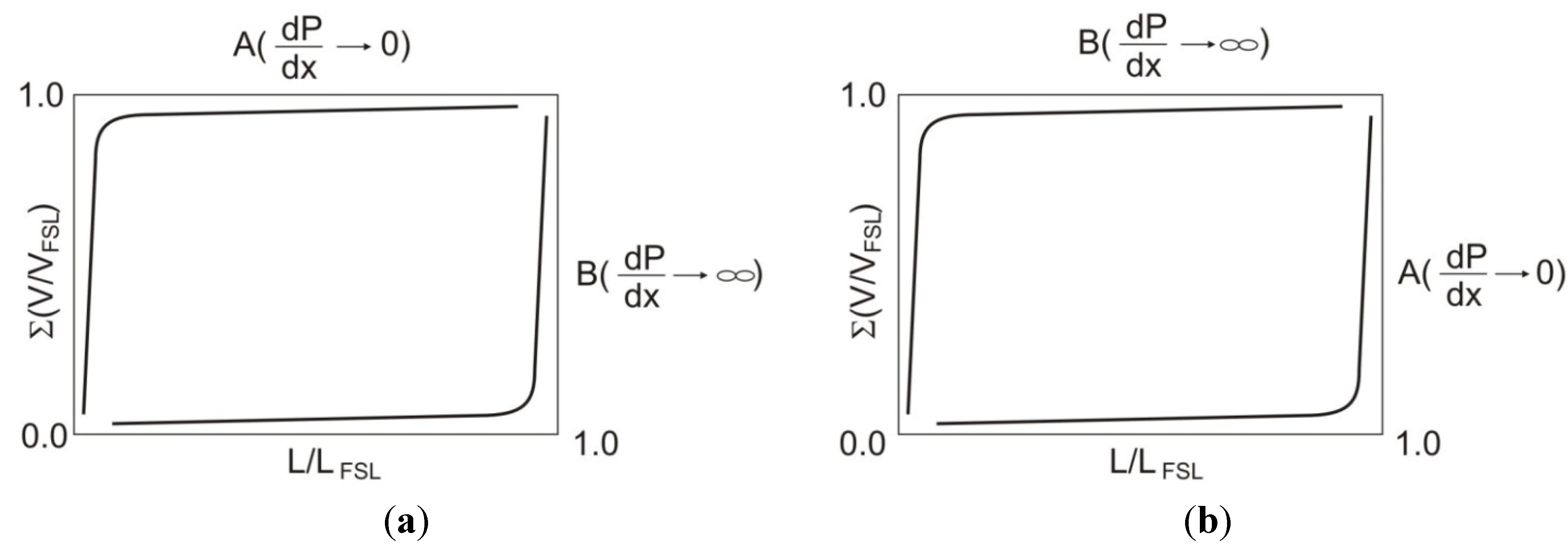
1.2. Annandale’s Method for Predicting Sediment Distribution in Reservoirs
2. Materials and Methods
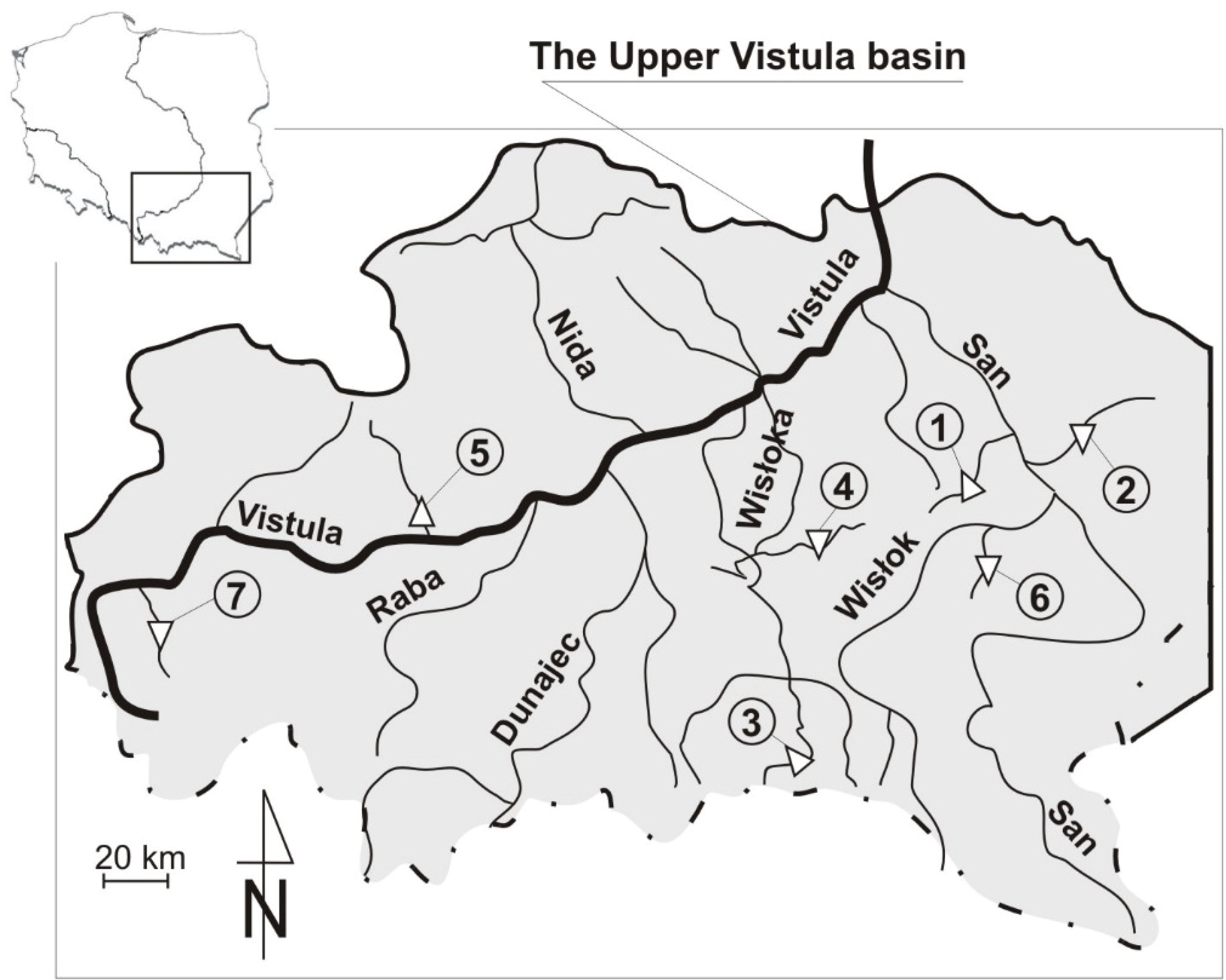
2.1. Characteristics of Research Objects

| Reservoir | Reservoir’s Capacity (103 m3) | Normal Water Level (m a.s.l.) | Surface of the Water Table (ha) | Mean Depth (m) | Length of the Reservoir (m) | Catchment Area (km2) |
|---|---|---|---|---|---|---|
| Brzóza Królewska | 48.8 | 195.00 | 6.13 | 0.80 | 440 | 30.40 |
| Ożanna | 252.0 | 172.90 | 18.00 | 1.40 | 950 | 136.30 |
| Krempna-1 | 119.1 | 370.00 | 3.20 | 3.72 | 400 | 165.30 |
| Krempna-2 | 112.0 | 370.00 | 3.20 | 3.50 | 400 | 165.30 |
| Cierpisz | 34.5 | 198.90 | 3.20 | 1.50 | 340 | 54.50 |
| Zesławice | 228.0 | 215.00 | 9.50 | 2.40 | 650 | 218.00 |
| Głuchów | 22.6 | 193.60 | 1.50 | 1.51 | 640 | 12.30 |
| Wapienica | 1100.0 | 477.60 | 17.50 | 6.29 | 1000 | 55.50 |
2.2. Research Methodology
- (1)
- the determination of the total volume of sediments in the reservoir (Ʃ VFSL);
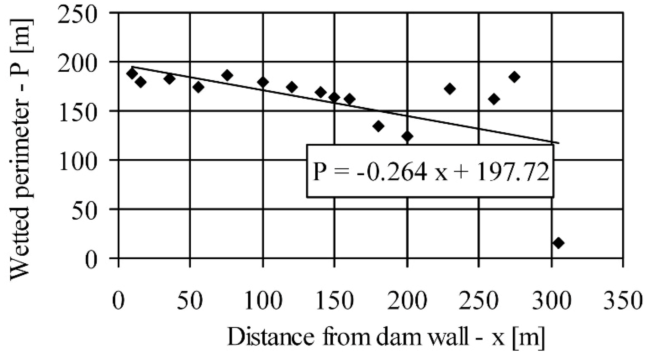
- (2)
- the development of mean value of longitudinal gradient dP/dx. For this purpose, a regression curve is drawn for a specific wetted perimeter (P) in each cross-section at a distance x from the dam’s wall;
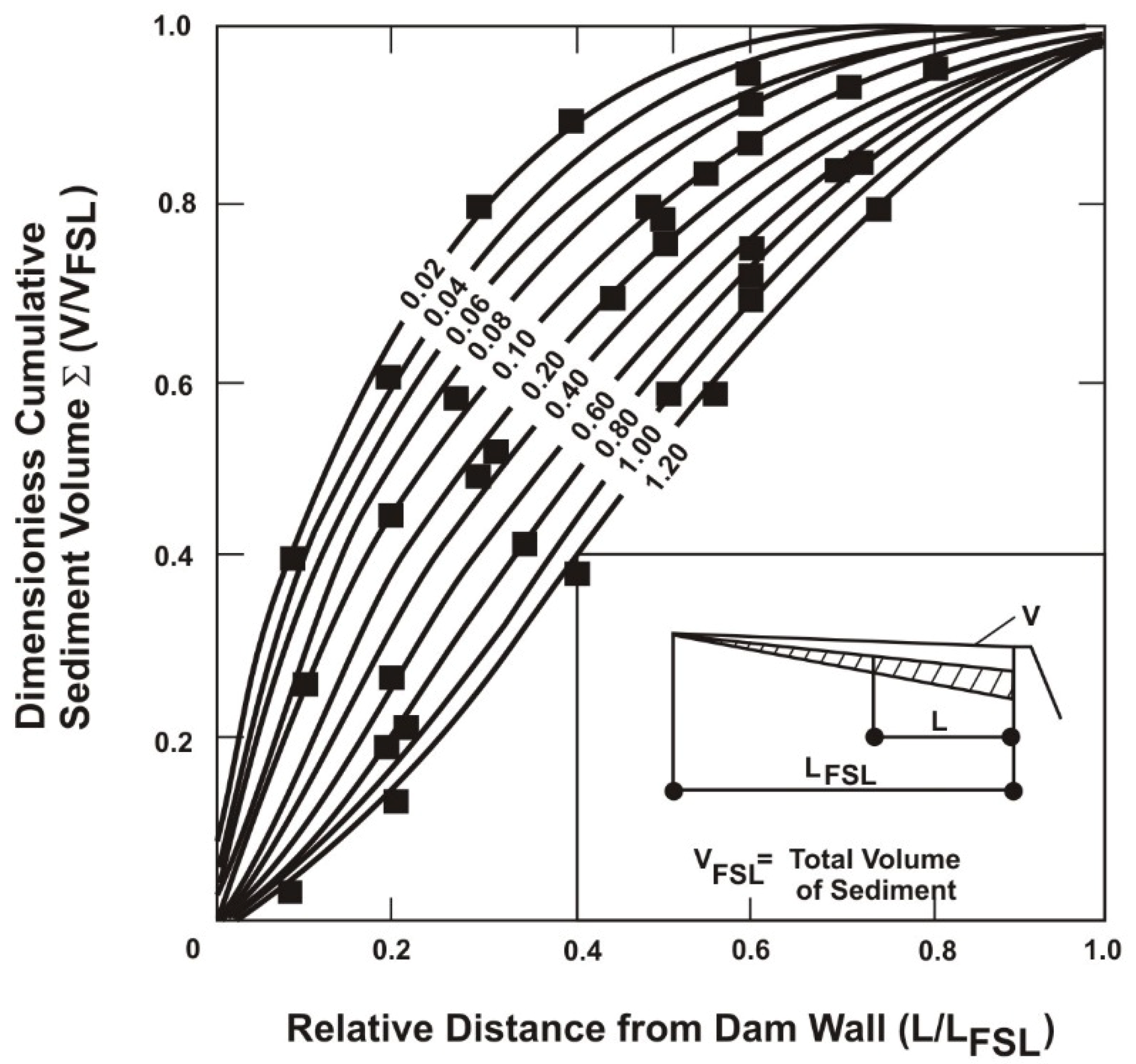
- (3)
- the determination of the dimensioned cumulative volume of deposited sediment (Ʃ(V/VFSL)) for each relative distance in the reservoir (L/LFSL) from the corresponding curve dP/dx (Figure 1);
- (4)
- the calculation and drawing of the graph of sediment load distribution depending on the relative distance in the reservoir.
3. Results and Discussion
3.1. Siltation Rate
| Reservoir | Year | Years of Operation | Volume of Sediment V (m3) | Silting Ratio in Several Years of Operation SR (%) | Mean Annual Silting Ratio SR, M (%) |
|---|---|---|---|---|---|
| Krempna-1 | 1986 | 15 | 35,660 | 29.9 | 2.0 |
| Krempna-2 | 1996 | 9 | 27,040 | 24.1 | 2.7 |
| 1997 | 10 | 30,460 | 27.2 | 2.7 | |
| 1998 | 11 | 34,640 | 30.9 | 2.8 | |
| 1999 | 12 | 38,000 | 33.9 | 2.8 | |
| 2000 | 13 | 40,140 | 35.8 | 2.8 | |
| 2002 | 15 | 44,200 | 39.5 | 2.6 | |
| 2003 | 16 | 44,900 | 40.1 | 2.5 | |
| 2005 | 18 | 45,810 | 40.9 | 2.3 | |
| Zesławice | 1968 | 2 | 26,970 | 11.8 | 5.9 |
| 1969 | 3 | 70,430 | 30.9 | 10.3 | |
| 1970 | 4 | 75,780 | 33.2 | 8.3 | |
| 1971 | 5 | 76,250 | 33.4 | 6.7 | |
| 1974 | 8 | 86,190 | 37.8 | 4.7 | |
| 1983 | 17 | 116,090 | 50.9 | 3.0 | |
| Głuchów | 2002 | 7 | 4,130 | 18.3 | 2.6 |
| 2009 | 14 | 5,890 | 26.1 | 1.9 | |
| Brzóza Królewska | 2002 | 7 | 4,180 | 8.5 | 1.2 |
| 2009 | 14 | 6,400 | 13.1 | 0.9 | |
| Ożanna | 1998 | 20 | 26,000 | 10.3 | 0.5 |
| 2003 | 25 | 30,200 | 12.0 | 0.5 | |
| Cierpisz | 1990 | 34 | 15,000 | 43.5 | 1.3 |
| 2001 | 11 | 6,100 | 17.7 | 1.6 | |
| 2003 | 13 | 6,750 | 19.6 | 1.5 | |
| Wapienica | 1967 | 36 | 24,250 | 2.2 | 0.1 |
| 2003 | 71 | 46,800 | 4.3 | 0.1 |
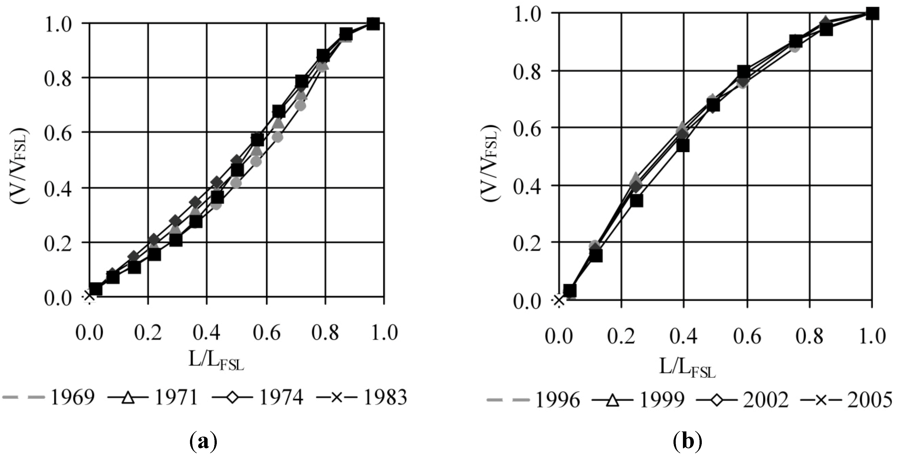
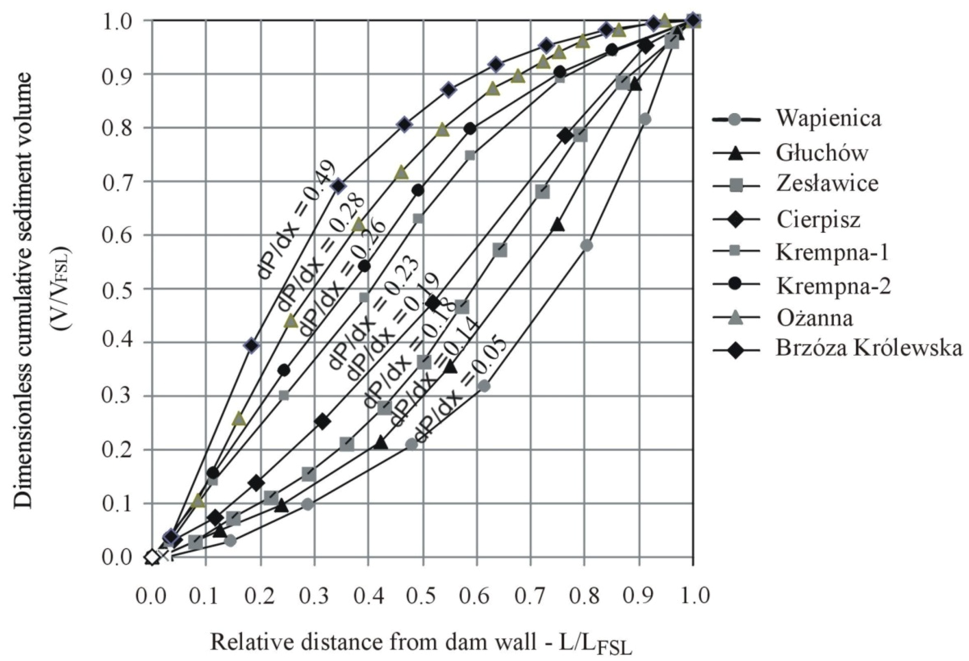
3.2. Sediment Distribution

| Reservoir | Longitudinal Gradient dP/dx (-) | Mean Annual Runoff Q (m3·s−1) | Capacity-Inflow Ratio C-I (%) |
|---|---|---|---|
| Brzóza Królewska | 0.49 | 0.224 | 0.69 |
| Ożanna | 0.28 | 1.006 | 0.79 |
| Krempna-1 | 0.23 | 2.030 | 0.37 |
| Krempna-2 | 0.26 | 2.030 | 0.35 |
| Cierpisz | 0.19 | 0.393 | 0.28 |
| Zesławice | 0.18 | 0.709 | 0.66 |
| Głuchów | 0.14 | 0.567 | 0.13 |
| Wapienica | 0.05 | 0.120 | 2.91 |
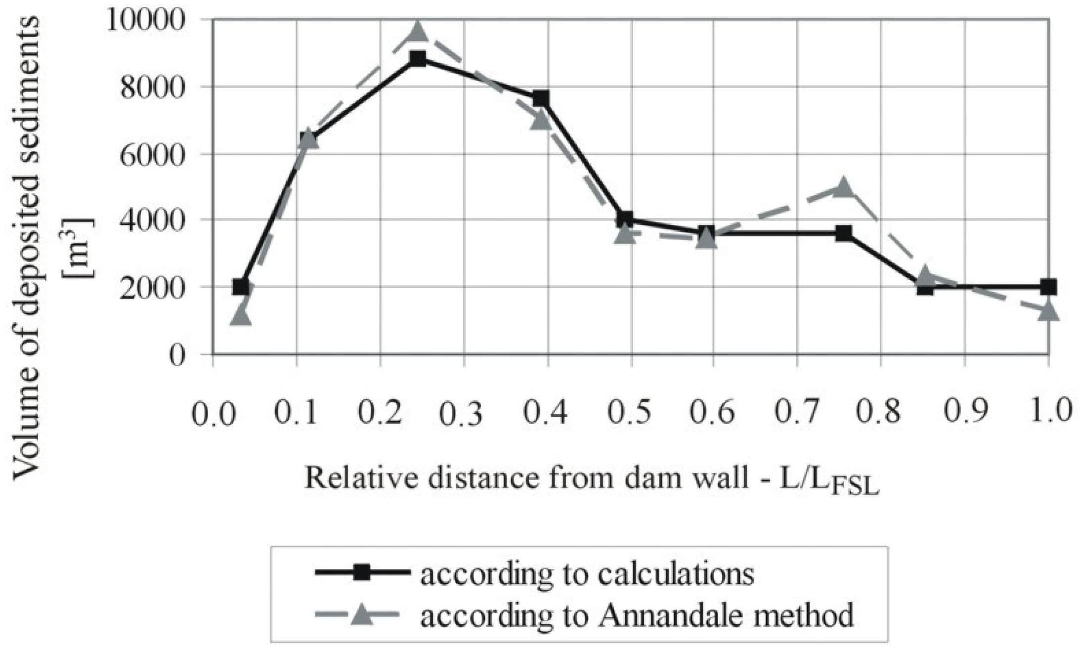
| Segment | L/LFSL | Σ(V/VFSL) | V/VFSL | Volume of Deposited Sediment (m3) | |
|---|---|---|---|---|---|
| A. Method | Measure. | ||||
| 1 | 0.03 | 0.05 | 0.05 | 1,351 | 877 |
| 2 | 0.11 | 0.21 | 0.16 | 4,327 | 4,150 |
| 3 | 0.25 | 0.43 | 0.22 | 5,949 | 5,900 |
| 4 | 0.39 | 0.62 | 0.19 | 5,138 | 4,959 |
| 5 | 0.49 | 0.72 | 0.10 | 2,704 | 2,763 |
| 6 | 0.59 | 0.81 | 0.09 | 2,434 | 1,657 |
| 7 | 0.75 | 0.90 | 0.09 | 2,433 | 3,401 |
| 8 | 0.85 | 0.95 | 0.05 | 1,352 | 1,931 |
| 9 | 1.00 | 1.00 | 0.05 | 1,352 | 1,402 |
| Sum | 1.00 | 27,040 | 27,040 | ||

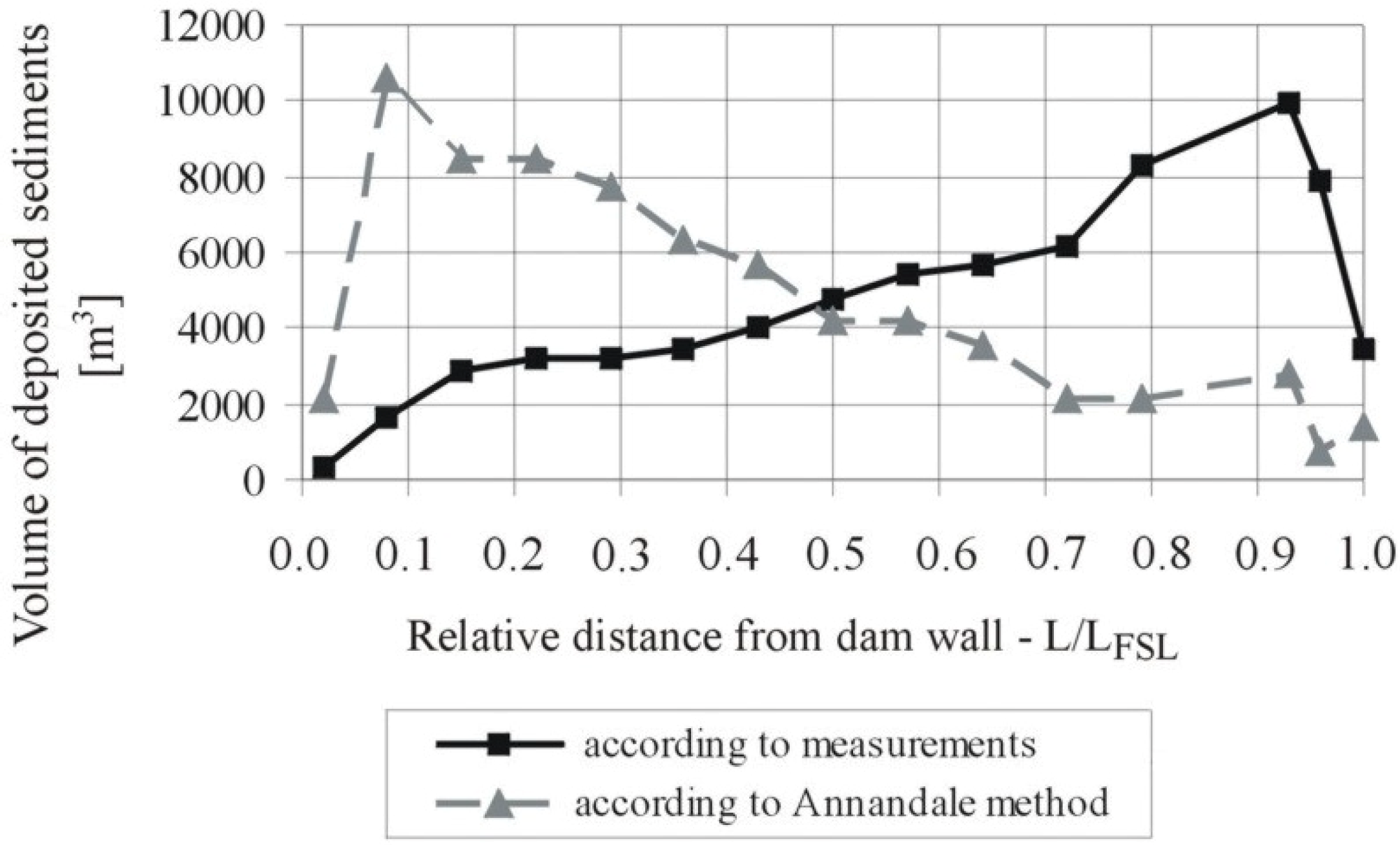
| Segment | L/LFSL | Σ(V/VFSL) | V/VFSL | Volume of Deposited Sediment (m3) | |
|---|---|---|---|---|---|
| A. Method | Measure. | ||||
| 1 | 0.02 | 0.03 | 0.03 | 2585 | 84 |
| 2 | 0.08 | 0.18 | 0.15 | 12,929 | 2,119 |
| 3 | 0.15 | 0.30 | 0.12 | 10,343 | 5,137 |
| 4 | 0.22 | 0.42 | 0.12 | 10,343 | 5,275 |
| 5 | 0.29 | 0.53 | 0.11 | 9,481 | 5,467 |
| 6 | 0.36 | 0.62 | 0.09 | 7,757 | 5,865 |
| 7 | 0.43 | 0.70 | 0.08 | 6,895 | 5,920 |
| 8 | 0.50 | 0.76 | 0.06 | 5,172 | 6,060 |
| 9 | 0.57 | 0.82 | 0.06 | 5,172 | 6,852 |
| 10 | 0.64 | 0.87 | 0.05 | 4,310 | 7,512 |
| 11 | 0.72 | 0.90 | 0.03 | 2,585 | 7,889 |
| Sum | 1.00 | 86,190 | 86,190 | ||

3.3. Modification of the Annandale Method

4. Conclusions
- -
- length is less than 1000 m;
- -
- capacity-inflow ratio ranges from a few per mille to a percent.
Acknowledgments
Conflicts of Interest
References
- Mahmood, K. Reservoir Sedimentation: Impact, Extent and Mitigation; Technical Paper No. 71; The World Bank: Washington, DC, USA, 1987. [Google Scholar]
- Hotchkiss, R.H.; Parker, G. Shock fitting of aggradational profiles due to backwater. J. Hydraul. Eng. 1991, 117, 1129–1144. [Google Scholar] [CrossRef]
- Fan, J.; Morris, G. Reservoir sedimentation. I: Delta and density current deposits. J. Hydraul. Eng. ASCE 1992, 118, 354–369. [Google Scholar] [CrossRef]
- Sloff, C.J. Sedimentation in Reservoirs. Ph.D. Thesis, Technical University of Delft, Delft, The Netherlands, 15 April 1997. [Google Scholar]
- De Cesare, G.; Schleiss, A.; Hermann, F. Impact of Turbidity Currents on Reservoir Sedimentation. J. Hydraul. Eng. ASCE 2001, 127, 6–16. [Google Scholar] [CrossRef]
- Batuca, G.D.; Jordaan, M.J., Jr. Silting and Desilting of Reservoirs; A.A. Balkema: Rotterdam, The Netherlands, 2000. [Google Scholar]
- Dewals, B.J.; Kantoush, S.A.; Erpicum, S.; Pirotton, M.; Schleiss, A.J. Experimental and numerical analysis of flow instabilities in rectangular shallow basins. Environ. Fluid Mech. 2008, 8, 31–54. [Google Scholar] [CrossRef]
- Dufresne, M.; Dewals, B.J.; Erpicum, S.; Archambeau, P.; Pirotton, M. Classification of flow patterns in rectangular shallow reservoirs. J. Hydraul. Res. 2010, 48, 197–204. [Google Scholar] [CrossRef]
- Camnasio, E.; Orsi, E.; Schleiss, A. Experimental study of velocity fields in rectangular shallow reservoirs. J. Hydraul. Res. 2011, 49, 352–358. [Google Scholar] [CrossRef]
- Lane, E. Some Hydraulic Engineering Aspects of Density Currents; Hydraulic Laboratory Report No. Hyd-373; U.S. Bureau of Reclamation: Denver, CO, USA, 1954.
- Normark, W.R.; Dickson, F.H. Man-made turbidity currents in Lake Superior. Sedimentology 1976, 23, 815–831. [Google Scholar] [CrossRef]
- Lambert, A. Turbidity currents from the Rhine River on the bottom of Lake Constance. Wasserwirtschaft 1982, 72, 1–4. (In German) [Google Scholar]
- Chikita, K. A field study on turbidity currents initiated from spring runoffs. Water Resour. Res. 1989, 25, 257–271. [Google Scholar] [CrossRef]
- Boix-Fayos, C.; de Vente, J.; Martinez-Mena, M.; Barbera, G.G.; Castillo, V. The impact of land use change and check-dams on catchment sediment yield. Hydrol. Process. 2008, 22, 4922–4935. [Google Scholar] [CrossRef]
- Leigh, C.A.; Burford, M.A.; Connolly, R.M.; Olley, J.M.; Saeck, E.; Sheldon, F.; Smart, J.C.R.; Bunn, S.E. Science to Support Management of Receiving Waters in an Event-Driven Ecosystem: From Land to River to Sea. Water 2013, 5, 780–797. [Google Scholar] [CrossRef]
- McBroom, M.; Thomas, T.; Zhang, Y. Soil Erosion and Surface Water Quality Impacts of Natural Gas Development in East Texas, USA. Water 2012, 4, 944–958. [Google Scholar] [CrossRef]
- Murthy, B.N. Life of Reservoir; Technical Report No. 19; Central Board of Irrigation and Power: New Delhi, India, 1977. [Google Scholar]
- Sloff, C.J. Reservoir Sedimentation: A Literature Survey; Communications on Hydraulic and Geotechnical Engineering, Report No. 91-2; Faculty of Civil Engineering, Delft University of Technology: Delft, The Netherlands, 1991. [Google Scholar]
- Lara, J.M.; Pemberton, E.L. Initial weight of deposited sediments. In Proceedings of the Federal Inter-Agency Sedimentation Conference, Jackson, MS, USA, 28 January–1 February 1963; USDA-ARS, Miscellaneous Publications: Jackson, MS, USA, 1963; Volume 970, pp. 818–845. [Google Scholar]
- Program of Small Retention of the Małopolski District; Project of Marshal Office of Małopolski District and Land Melioration and Water Units Board of Małopolski Province in Cracow: Cracow, Poland, 2004; p. 47. (In Polish)
- White, P.; Labadz, J.C.; Buchter, D.P. Sediment yield estimation from reservoir studies: An appraisal of variability in the southern Pennines of the UK. In Erosion and Sediment Yield. Global and Regional Perspectives; International Association of Hydrological Sciences Publication: Exeter, UK, 1996; Volume 236, pp. 163–173. [Google Scholar]
- Senzanje, A.; Chimbari, M. Inventory of Small Dams in Africa—A Case Study for Zimbabwe; Draft Report for Water, Health and Environment; The International Management Institute (IWMI): Colombo, Sri Lanka, 2002. [Google Scholar]
- Neto, I.E.L.; Wiegand, M.C.; de Araújo, J.C. Sediment redistribution due to a dense reservoir network in a large semi-arid Brazilian basin. Hydrol. Sci. J. 2011, 56, 319–333. [Google Scholar] [CrossRef]
- Cristofano, E.A. Area-Increment Method for Distributing Sediment in a Reservoir; US Bureau of Reclamation: Albuquerque, NM, USA, 1953.
- Borland, W.M.; Miller, C.R. Distribution of sediment in large reservoirs. J. Hydraul. Eng. Div. ASCE 1958, 84, 1–18. [Google Scholar]
- Lara, J.M. Revision of the Procedure to Compute Sediment Distribution in Large Reservoirs; US Bureau of Reclamation: Denver, CO, USA, 1962.
- Hobbs, B.L. Forecasting Distribution of Sediment Deposits in Large Reservoirs; Appendix I, ETL 1110-2-64; Department of the Army, Office of the Chief of Engineers: Washington, DC, USA, 1969.
- Borland, W.M. Reservoir Sedimentation, River Mechanics; Shen, H.W., Ed.; Water Resources Publisher: Fort Collins, CO, USA, 1970; Chapter 29; pp. 1–38. [Google Scholar]
- Pemberton, E.L. Reservoir Sedimentation. In Proceedings of the US-Japan Seminar on Sedimentation and Erosion, Honolulu, HI, USA, 20–24 March 1978.
- Qian, N. Reservoir sedimentation and slope stability, technical and environmental effects. General Report, G.R.54. In Proceedings of the 14th International Commission on Large Dams Congress, Rio de Janeiro, Brazil, 14–17 May 1982.
- Annandale, G.W. Predicting the distribution of deposited sediment in southern African reservoirs. In Challenges in African Hydrology and Water Resources (Proceedings of the Harare Symposium, July 1984); International Association of Hydrological Sciences Publication: Harare, Zimbabwe, 1984; Volume 144, pp. 549–558. [Google Scholar]
- Mohammadzadeh-Habibi, J.; Heidarpour, M. New empirical method for prediction of sediment distribution in reservoirs. J. Hydrol. Eng. 2010, 15, 813–821. [Google Scholar] [CrossRef]
- Rahmanian, M.R.; Banhashemi, M.A. A new empirical reservoir shape function to define sediment distribution pattern in dam reservoirs. IJST Trans. Civ. Eng. 2012, 36, 79–92. [Google Scholar]
- Michalec, B. Qualification of the distribution of bottom sediments in small water reservoir using the relative depth shape. Funct. Eng. Prot. Environ. 2013, 16, 425–434. (In Polish) [Google Scholar]
- Rooseboom, A. Reservoir sediment deposition rates. In Proceedings of the 12th ICOLD Congress, Mexico City, Mexico, 29 March–2 April 1976; pp. 184–196.
- Verstraeten, G.; Poesen, J. Estimating trap efficiency of small reservoirs and ponds: Methods and implications for the assessment of sediment yield. Prog. Phys. Geogr. 2000, 24, 219–251. [Google Scholar] [CrossRef]
- Verstraeten, G.; Poesen, J. Modelling the long-term sediment trap efficiency of small ponds. Hydrol. Process. 2001, 15, 2797–2819. [Google Scholar]
- Bussi, G.; Rodríguez-Lloveras, X.; Francés, F.; Benito, G.; Sánchez-Moya, Y.; Sopeña, A. Sediment yield model implementation based on check dam infill stratigraphy in a semiarid Mediterranean catchment. Hydrol. Earth Syst. Sci. 2013, 17, 3339–3354. [Google Scholar]
- Tarnawski, M.; Michalec, B. Assessment of Agricultural Utilization of Bottom Sediment; Research Project No. N305 295037 (2009–2012); Ministry of Science and High Education: Kraków, Poland, 2012. (In Polish)
- Michalec, B. Appraisal of silting intensity of small water reservoirs in the Upper Vistula river basin. In Scientific Fascicles; Agricultural University Cracow: Kraków, Poland, 2008; p. 193. (In Polish) [Google Scholar]
- Rausch, D.L.; Heinemann, H.G. Measurement of reservoir sedimentation. In Erosion and Sediment Yield:Some Methods of Measurement and Modelling; Geobooks: Norwich, England, 1984; pp. 179–200. [Google Scholar]
- Bednarczyk, T.; Michalec, B.; Tarnawski, M. The Evaluation of the Silting Ratio of Small Reservoirs in Carpathians and Silting Forecast on the Background of Erosion Processes in the Catchments; Research Project No. 6 P06S 016 21 (1998–2001); Ministry of Science and High Education: Kraków, Poland, 2001. (In Polish)
- Brune, G.M. Trap efficiency of reservoirs. Trans. Am. Geophys. Union 1953, 34, 407–418. [Google Scholar] [CrossRef]
- Punzet, J. The Resources the Water Drainage Areas of the Upper Vistula. Average Flows—Seasonal Distribution and Changeability in Time and Space; Polish Scientific Publishers PWN: Warsaw, Poland, 1983; Volume 192. (In Polish) [Google Scholar]
- Dendy, F.E. Distribution of sediment deposits in small reservoirs. Trans. Am. Soc. Agric. Eng. 1982, 25, 100–104. [Google Scholar] [CrossRef]
- Garg, V.; Jothiprakash, V. Trap efficiency estimation of a large reservoirs. ISJ J. Hydraul. Eng. 2008, 14, 88–101. [Google Scholar] [CrossRef]
- Jebari, S.; Berndtsson, R.; Bahri, A.; Boufaroua, M. Spatial soil loss risk and reservoir siltation in semi-arid Tunisia. Hydrol. Sci. J. 2010, 55, 121–137. [Google Scholar] [CrossRef]
- Heidarnejad, M.S.; Golmaee, S.H.; Mosaedi, A.; Ahmadi, M.Z. Estimation of sediment volume in Karaj Dam Reservoir (Iran) by hydrometry method and a comparison with hydrography method. Lake Res. Manag. 2006, 22, 233–239. [Google Scholar] [CrossRef]
- Araújo, J.C.; Günter, A.; Bronstert, A. Loss of reservoir volume by sediment deposition and its impact on water availability in semiarid Brazil. Hydrol. Sci. J. 2006, 51, 157–170. [Google Scholar] [CrossRef]
- Hartung, F. Ursache und Verhuetung der Staumraumverlandung bei Talsperren. Wasserwirtschaft 1959, 1, 3–13. (In German) [Google Scholar]
- Dendy, F.E. Sediment trap efficiency of small reservoirs. Trans. Am. Soc. Agric. Eng. 1974, 17, 898–908. [Google Scholar] [CrossRef]
- Wiśniewski, B.; Kutrowski, M. Special Constructions in Water Managements. Water Reservoirs. Predicting Silting Rate. Manual; Water Management Study and Design Office “Hydroprojekt”: Warsaw, Poland, 1973; p. 55. (In Polish) [Google Scholar]
© 2014 by the authors; licensee MDPI, Basel, Switzerland. This article is an open access article distributed under the terms and conditions of the Creative Commons Attribution license (http://creativecommons.org/licenses/by/4.0/).
Share and Cite
Michalec, B. The Use of Modified Annandale’s Method in the Estimation of the Sediment Distribution in Small Reservoirs—A Case Study. Water 2014, 6, 2993-3011. https://doi.org/10.3390/w6102993
Michalec B. The Use of Modified Annandale’s Method in the Estimation of the Sediment Distribution in Small Reservoirs—A Case Study. Water. 2014; 6(10):2993-3011. https://doi.org/10.3390/w6102993
Chicago/Turabian StyleMichalec, Bogusław. 2014. "The Use of Modified Annandale’s Method in the Estimation of the Sediment Distribution in Small Reservoirs—A Case Study" Water 6, no. 10: 2993-3011. https://doi.org/10.3390/w6102993
APA StyleMichalec, B. (2014). The Use of Modified Annandale’s Method in the Estimation of the Sediment Distribution in Small Reservoirs—A Case Study. Water, 6(10), 2993-3011. https://doi.org/10.3390/w6102993