
A Numerical Study of Solitary Wave Processes over Idealized Atolls


Abstract
1. Introduction
2. Brief Introduction of the Numerical Method
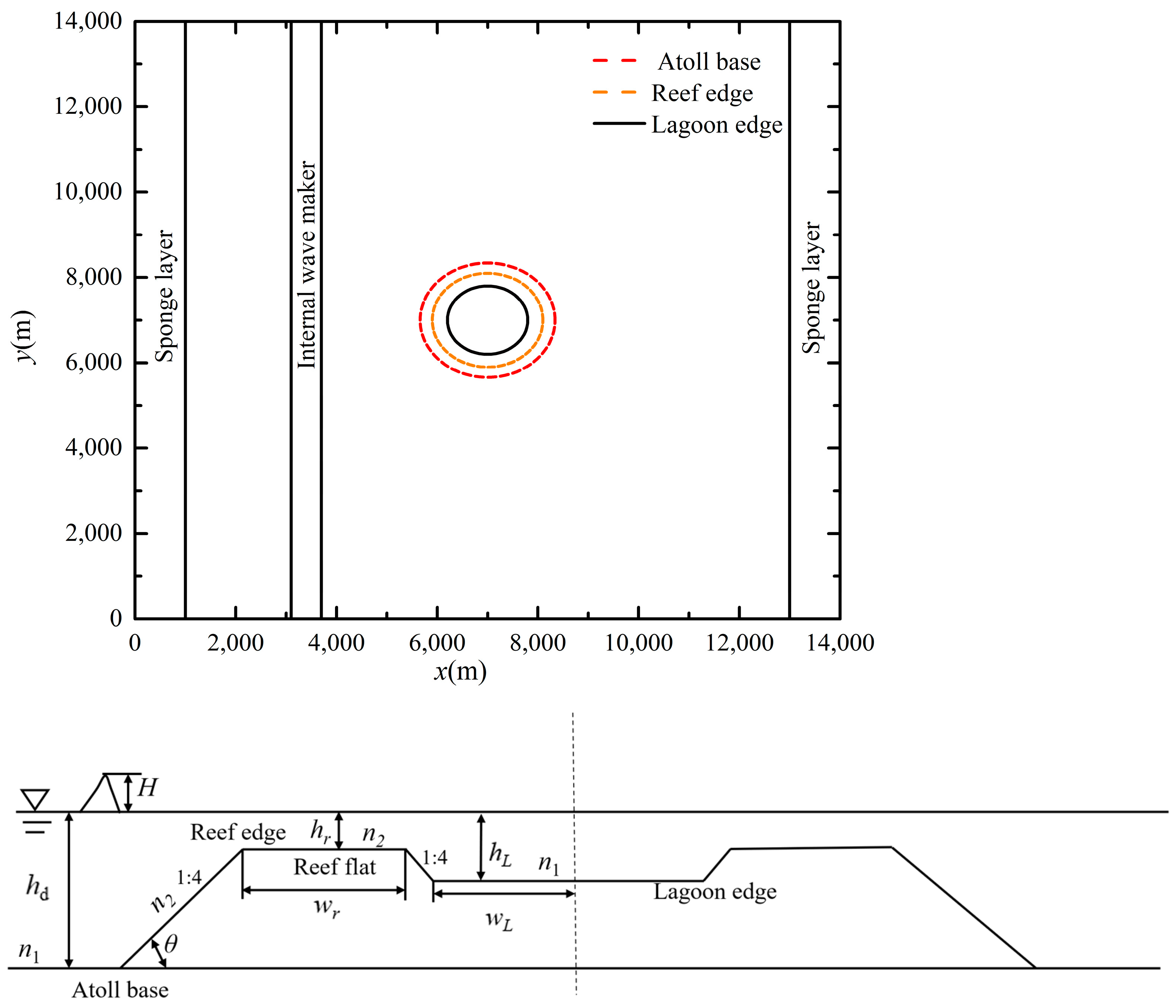
3. Typical Propagation Process over an Idealized Atoll
4. Influences of Morphological and Hydrodynamic Parameters
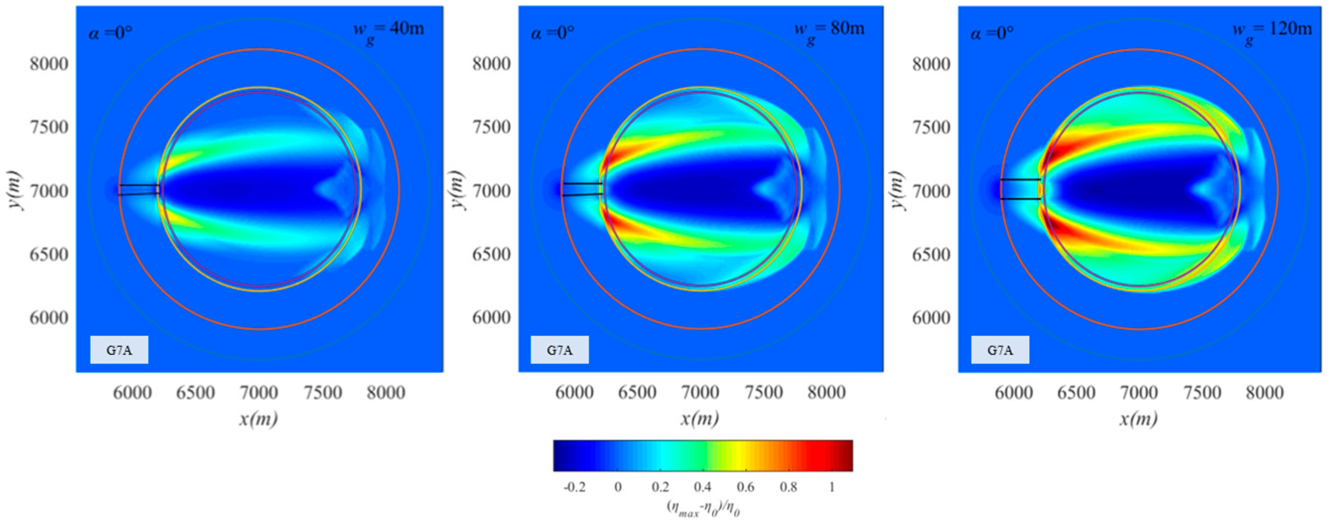
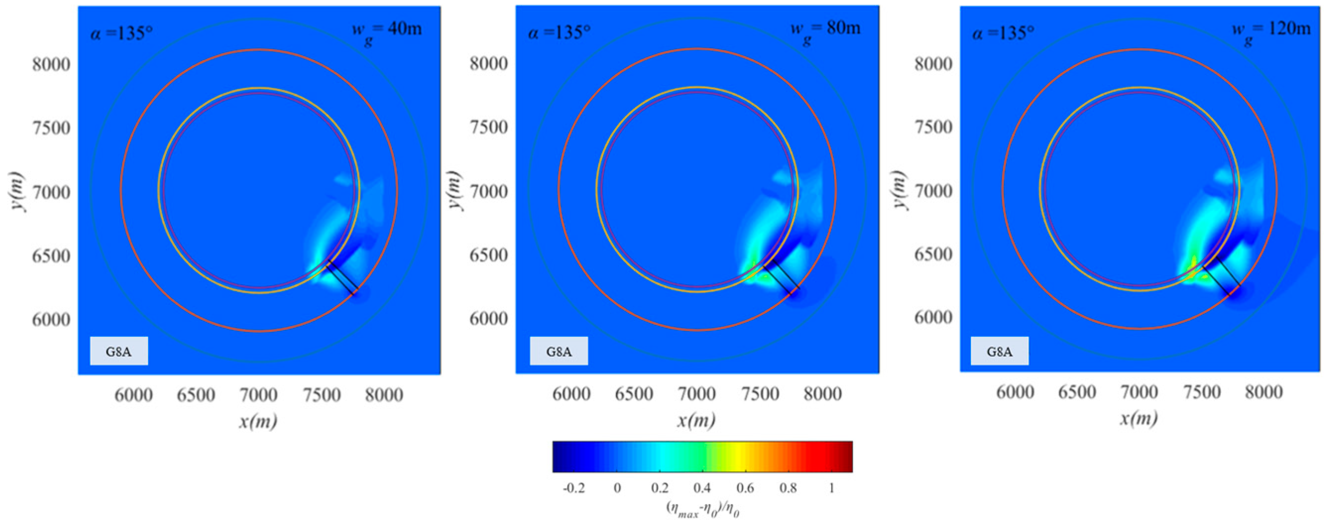
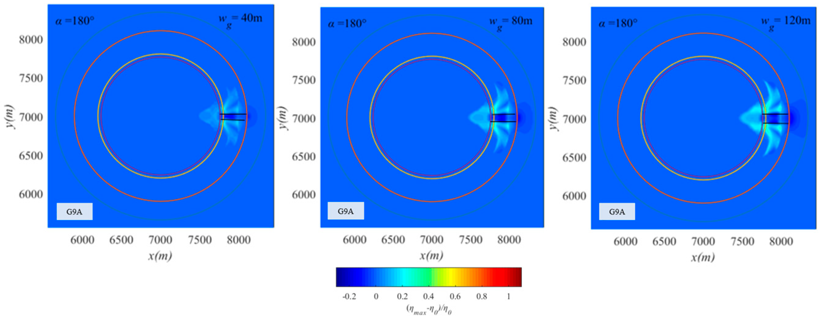
5. Effects of Channel Location and Width
6. Conclusions
- (1)
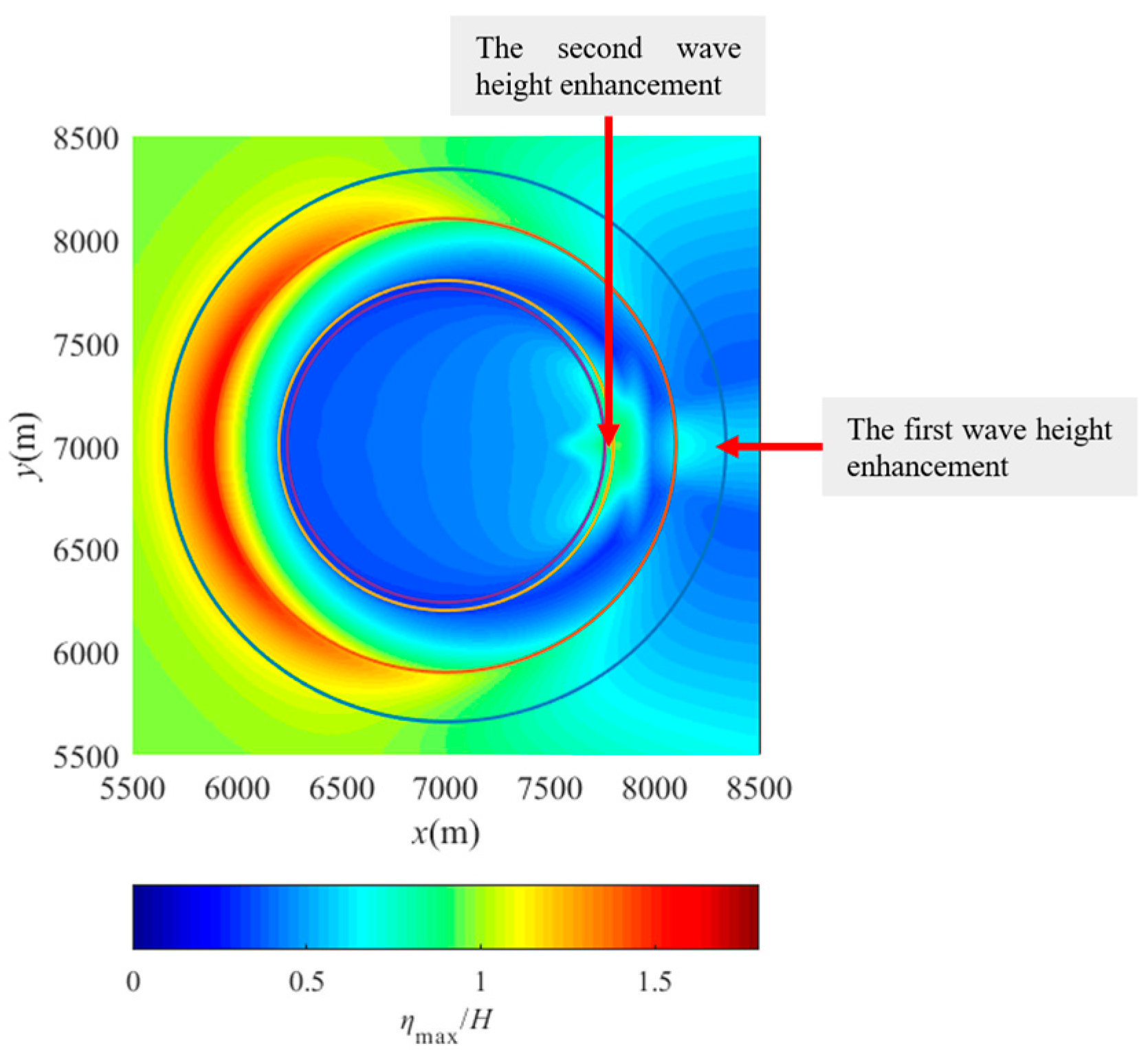
- In general, the coral reefs of an atoll can provide effective shelter for the lagoon inside the atoll. During the solitary wave propagation over an atoll, diffracted waves can be trapped by the atoll at the lee side and ultimately collide with the water body propagating in the lagoon, forming an area of wave height enhancement near the lagoon edge at the lee side.
- (2)
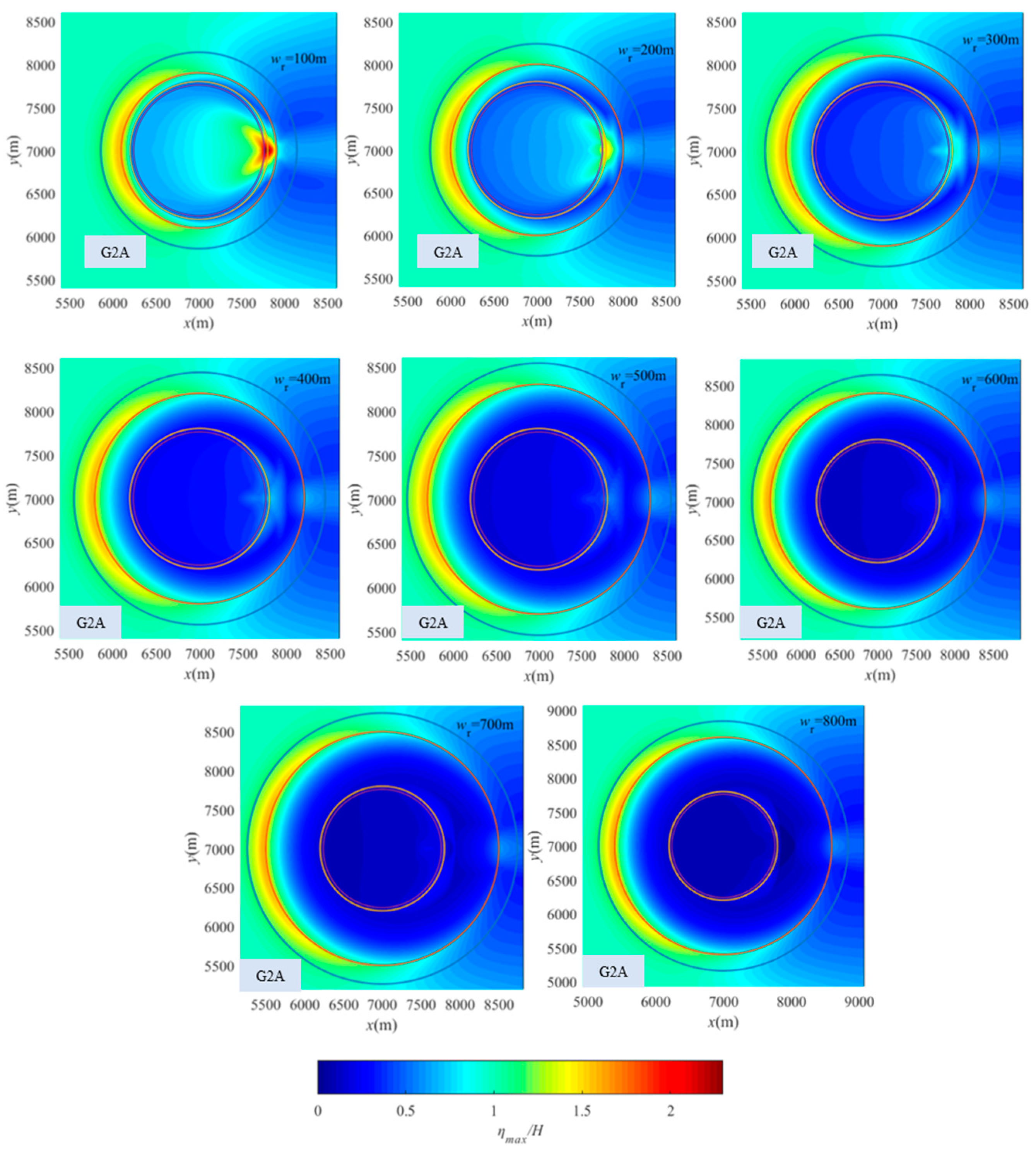
- The maximum surface elevations over the entire atoll increase significantly with the rise in reef flat water depth, or reduced reef flat width and reef surface roughness, while the lagoon water depth and fore-reef slope have minimal influence. As the reef flat water depth increases or the reef surface roughness decreases, the extent of the wave height enhancement area at the lee side also undergoes an expansion.
- (3)
- The influence of the channel mainly presents as two regions of increased wave heights starting from both sides of the channel. The more the position of the channel deviates from the front of the atoll, the smaller the increase effect and range of the two regions will be. As the channel width increases, the increase effect and range of the two regions will also increase.
Author Contributions
Funding
Data Availability Statement
Conflicts of Interest
References
- Liu, W.; Qian, F.; Ning, Y.; Cheng, R. 2DH Numerical Study of Solitary Wave Processes around an Idealized Reef-Fringed Island. Water 2024, 16, 1991. [Google Scholar] [CrossRef]
- Zheng, J.; Yao, Y.; Chen, S.; Chen, S.; Zhang, Q. Laboratory study on wave-induced setup and wave-driven current in a 2DH reef-lagoon-channel system. Coast. Eng. 2020, 162, 103772. [Google Scholar] [CrossRef]
- Adger, W.N.; Hughes, T.P.; Folke, C.; Carpenter, S.R.; Rockström, J. Social-Ecological Resilience to Coastal Disasters. Science 2005, 309, 1036. [Google Scholar] [CrossRef] [PubMed]
- Baird, A.H.; Campbell, S.J.; Anggoro, A.W.; Ardiwijaya, R.L.; Fadli, N.; Herdiana, Y.; Kartawijaya, T.; Mahyiddin, D.; Mukminin, A.; Pardede, S.T.; et al. Acehnese Reefs in the Wake of the Asian Tsunami. Curr. Biol. 2005, 15, 1926–1930. [Google Scholar] [CrossRef] [PubMed]
- Fernando, H.J.S.; McCulley, J.L.; Mendis, S.G.; Perera, K. Coral poaching worsens tsunami destruction in Sri Lanka. Eos Trans. Am. Geophys. Union 2005, 86, 301–304. [Google Scholar] [CrossRef]
- Goff, J.; Liu, P.L.F.; Higman, B.; Morton, R.; Jaffe, B.E.; Fernando, H.; Lynett, P.; Fritz, H.; Synolakis, C.; Fernando, S. Sri Lanka Field Survey after the December 2004 Indian Ocean Tsunami. Earthq. Spectra 2006, 22, 155–172. [Google Scholar] [CrossRef]
- Fernando, H.J.S.; Samarawickrama, S.P.; Balasubramanian, S.; Hettiarachchi, S.S.L.; Voropayev, S. Effects of porous barriers such as coral reefs on coastal wave propagation. J. Hydro-Environ. Res. 2008, 1, 187–194. [Google Scholar] [CrossRef]
- Shao, K.; Liu, W.; Gao, Y.; Ning, Y. The influence of climate change on tsunami-like solitary wave inundation over fringing reefs. J. Integr. Environ. Sci. 2019, 16, 71–88. [Google Scholar] [CrossRef]
- Quiroga, P.D.; Cheung, K.F. Laboratory study of solitary-wave transformation over bed-form roughness on fringing reefs. Coast. Eng. 2013, 80, 35–48. [Google Scholar] [CrossRef]
- Yao, Y.; He, F.; Tang, Z.; Liu, Z. A study of tsunami-like solitary wave transformation and run-up over fringing reefs. Ocean Eng. 2018, 149, 142–155. [Google Scholar] [CrossRef]
- Zhou, Q.; Zhan, J.-M.; Li, Y.S. Parametric Investigation of Breaking Solitary Wave Over Fringing Reef Based on Shock-Capturing Boussinesq Model. Coast. Eng. J. 2016, 58, 1650007. [Google Scholar] [CrossRef]
- Ning, Y.; Liu, W.; Sun, Z.; Zhao, X.; Zhang, Y. Parametric study of solitary wave propagation and runup over fringing reefs based on a Boussinesq wave model. J. Mar. Sci. Technol. 2019, 24, 512–525. [Google Scholar] [CrossRef]
- Liu, W.; Shao, K.; Ning, Y. A Study of the Maximum Momentum Flux in the Solitary Wave Run-Up Zone over Back-Reef Slopes Based on a Boussinesq Model. J. Mar. Sci. Eng. 2019, 7, 109. [Google Scholar] [CrossRef]
- Synolakis, C.E. The runup of solitary waves. J. Fluid Mech. 1987, 185, 523–545. [Google Scholar] [CrossRef]
- Yeh, H.; Liu, P.; Briggs, M.; Synolakis, C. Propagation and amplification of tsunamis at coastal boundaries. Nature 1994, 372, 353–355. [Google Scholar] [CrossRef]
- Su, S.-F.; Ma, G. Modeling two-dimensional infragravity motions on a fringing reef. Ocean Eng. 2018, 153, 256–267. [Google Scholar] [CrossRef]
- Shi, F.; Kirby, J.T.; Harris, J.C.; Geiman, J.D.; Grilli, S.T. A high-order adaptive time-stepping TVD solver for Boussinesq modeling of breaking waves and coastal inundation. Ocean Model. 2012, 43–44, 36–51. [Google Scholar] [CrossRef]
- Chen, Q. Fully nonlinear Boussinesq-type equations for waves and currents over porous beds. J. Eng. Mech. 2006, 132, 220–230. [Google Scholar] [CrossRef]
- Kennedy, A.B.; Chen, Q.; Kirby, J.T.; Dalrymple, R.A. Boussinesq modeling of wave transformation, breaking, and runup. I: 1D. J. Waterw. Port Coast. Ocean Eng. 2000, 126, 39–47. [Google Scholar] [CrossRef]
- Madsen, P.A.; Sørensen, O.R.; Schäffer, H.A. Surf zone dynamics simulated by a Boussinesq type model. Part I. Model description and cross-shore motion of regular waves. Coast. Eng. 1997, 32, 255–287. [Google Scholar] [CrossRef]
- Yao, Y.; Huang, Z.; Monismith, S.G.; Lo, E.Y.M. 1DH Boussinesq modeling of wave transformation over fringing reefs. Ocean Eng. 2012, 47, 30–42. [Google Scholar] [CrossRef]
- Ning, Y.; Liu, W.; Zhao, X.; Zhang, Y.; Sun, Z. Study of irregular wave run-up over fringing reefs based on a shock-capturing Boussinesq model. Appl. Ocean Res. 2019, 84, 216–224. [Google Scholar] [CrossRef]
- Briggs, M.J.; Synolakis, C.E.; Harkins, G.S.; Green, D.R. Laboratory experiments of tsunami runup on a circular island. Pure Appl. Geophys. 1995, 144, 569–593. [Google Scholar] [CrossRef]
- Chen, Q.; Kirby James, T.; Dalrymple Robert, A.; Kennedy Andrew, B.; Chawla, A. Boussinesq Modeling of Wave Transformation, Breaking, and Runup. II: 2D. J. Waterw. Port Coast. Ocean Eng. 2000, 126, 48–56. [Google Scholar] [CrossRef]
- Quataert, E.; Storlazzi, C.; Rooijen, A.; Cheriton, O.; Van Dongeren, A. The influence of coral reefs and climate change on wave-driven flooding of tropical coastlines. Geophys. Res. Lett. 2015, 42, 6407–6415. [Google Scholar] [CrossRef]
- Wang, X. Study on Engineering Geological Properties of Coral reefs and Feasibility of Large Project Construction on Nansha Islands. Ph.D. Thesis, The Chinese Acadame of Sciences, Beijing, China, 2008. [Google Scholar]
- Gelfenbaum, G.; Apotsos, A.; Stevens, A.W.; Jaffe, B. Effects of fringing reefs on tsunami inundation: American Samoa. Earth-Sci. Rev. 2011, 107, 12–22. [Google Scholar] [CrossRef]
- Vermeer, M.; Rahmstorf, S. Global sea level linked to global temperature. Proc. Natl. Acad. Sci. USA 2009, 106, 21527. [Google Scholar] [CrossRef] [PubMed]
- Grinsted, A.; Moore, J.C.; Jevrejeva, S. Reconstructing sea level from paleo and projected temperatures 200 to 2100 ad. Clim. Dyn. 2010, 34, 461–472. [Google Scholar] [CrossRef]
- Yao, Y.; Chen, S.; Zheng, J.; Zhang, Q.; Chen, S. Laboratory study on wave transformation and run-up in a 2DH reef-lagoon-channel system. Ocean Eng. 2020, 215, 107907. [Google Scholar] [CrossRef]


| Case No. | H (m) | hd (m) | wr (m) | wL (m) | hr (m) | hL (m) | cot θ | n2 | n1 |
|---|---|---|---|---|---|---|---|---|---|
| 1A | 3 | 62 | 300 | 800 | 2 | 12 | 4 | 0.09 | 0.02 |
| Group No. | H (m) | hd (m) | wr (m) | hr (m) | hL (m) | cot θ | n2 |
|---|---|---|---|---|---|---|---|
| G1A | 3 | 62 | 300 | 1~6 | 12 | 4 | 0.09 |
| G2A | 3 | 62 | 50~800 | 2 | 12 | 4 | 0.09 |
| G3A | 3 | 62 | 300 | 2 | 12 | 4 | 0.02~0.09 |
| G4A | 3 | 62 | 300 | 2 | 12 | 4~18 | 0.09 |
| G5A | 3 | 62 | 300 | 2 | 7~22 | 4 | 0.09 |
| Group No. | H (m) | hd (m) | wr (m) | hr (m) | hL (m) | Wg (m) | cot θ | α (°) | n2 |
|---|---|---|---|---|---|---|---|---|---|
| G6A | 3 | 62 | 300 | 2 | 12 | 40 | 4 | 0~180 | 0.09 |
| G7A | 3 | 62 | 300 | 2 | 12 | 40~120 | 4 | 0 | 0.09 |
| G8A | 3 | 62 | 300 | 2 | 12 | 40~120 | 4 | 135 | 0.09 |
| G9A | 3 | 62 | 300 | 2 | 12 | 40~120 | 4 | 180 | 0.09 |
Disclaimer/Publisher’s Note: The statements, opinions and data contained in all publications are solely those of the individual author(s) and contributor(s) and not of MDPI and/or the editor(s). MDPI and/or the editor(s) disclaim responsibility for any injury to people or property resulting from any ideas, methods, instructions or products referred to in the content. |
© 2025 by the authors. Licensee MDPI, Basel, Switzerland. This article is an open access article distributed under the terms and conditions of the Creative Commons Attribution (CC BY) license (https://creativecommons.org/licenses/by/4.0/).
Share and Cite
Liu, W.; Luo, R.; Luo, Z.; Zhao, X. A Numerical Study of Solitary Wave Processes over Idealized Atolls. Water 2025, 17, 635. https://doi.org/10.3390/w17050635
Liu W, Luo R, Luo Z, Zhao X. A Numerical Study of Solitary Wave Processes over Idealized Atolls. Water. 2025; 17(5):635. https://doi.org/10.3390/w17050635
Chicago/Turabian StyleLiu, Weijie, Runxin Luo, Zhengyang Luo, and Xizeng Zhao. 2025. "A Numerical Study of Solitary Wave Processes over Idealized Atolls" Water 17, no. 5: 635. https://doi.org/10.3390/w17050635
APA StyleLiu, W., Luo, R., Luo, Z., & Zhao, X. (2025). A Numerical Study of Solitary Wave Processes over Idealized Atolls. Water, 17(5), 635. https://doi.org/10.3390/w17050635