
Origin of Fracture-Controlled Conduits in Calcite-Rich Highly Productive Aquifers Impregnated with Diagenetic Silica

Abstract
1. Introduction
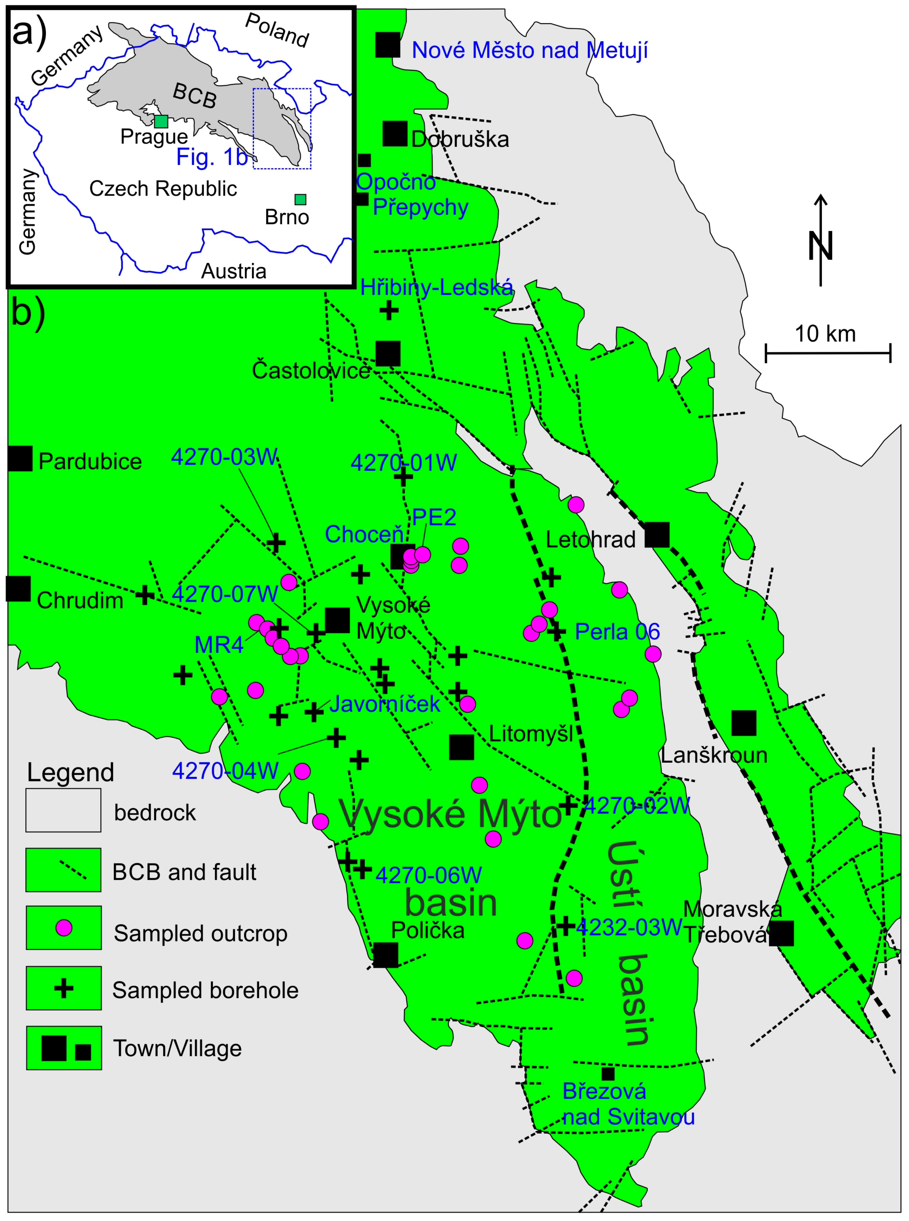
2. Study Area
3. Methods
3.1. Calcimetry, Dissolution Tests, Porosity, and Tensile Strength
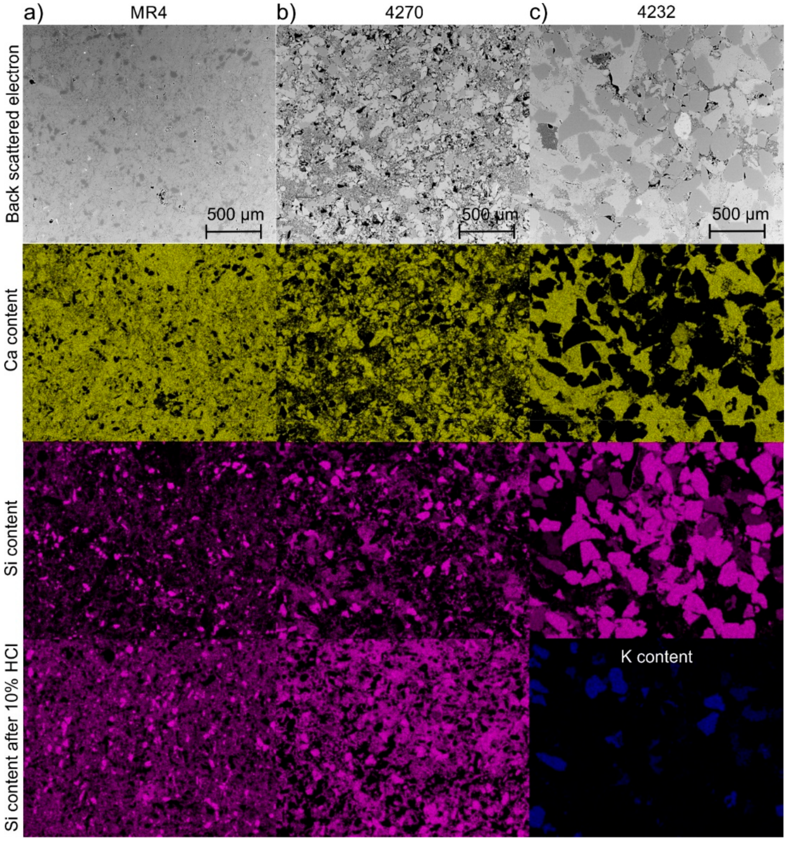
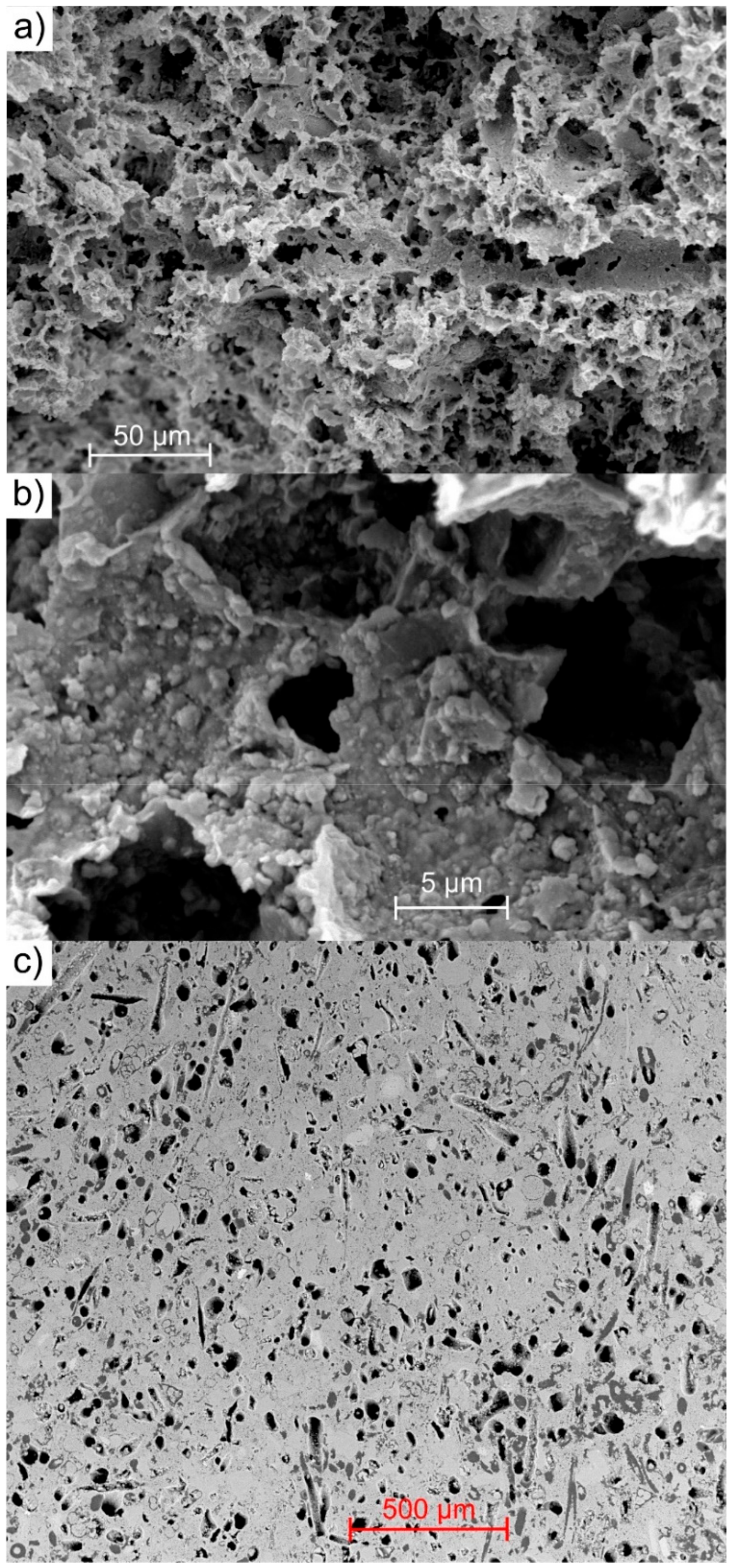
3.2. Scanning Electron Microscopy and Elemental Analysis
3.3. Field Documentation and Well Data
4. Results
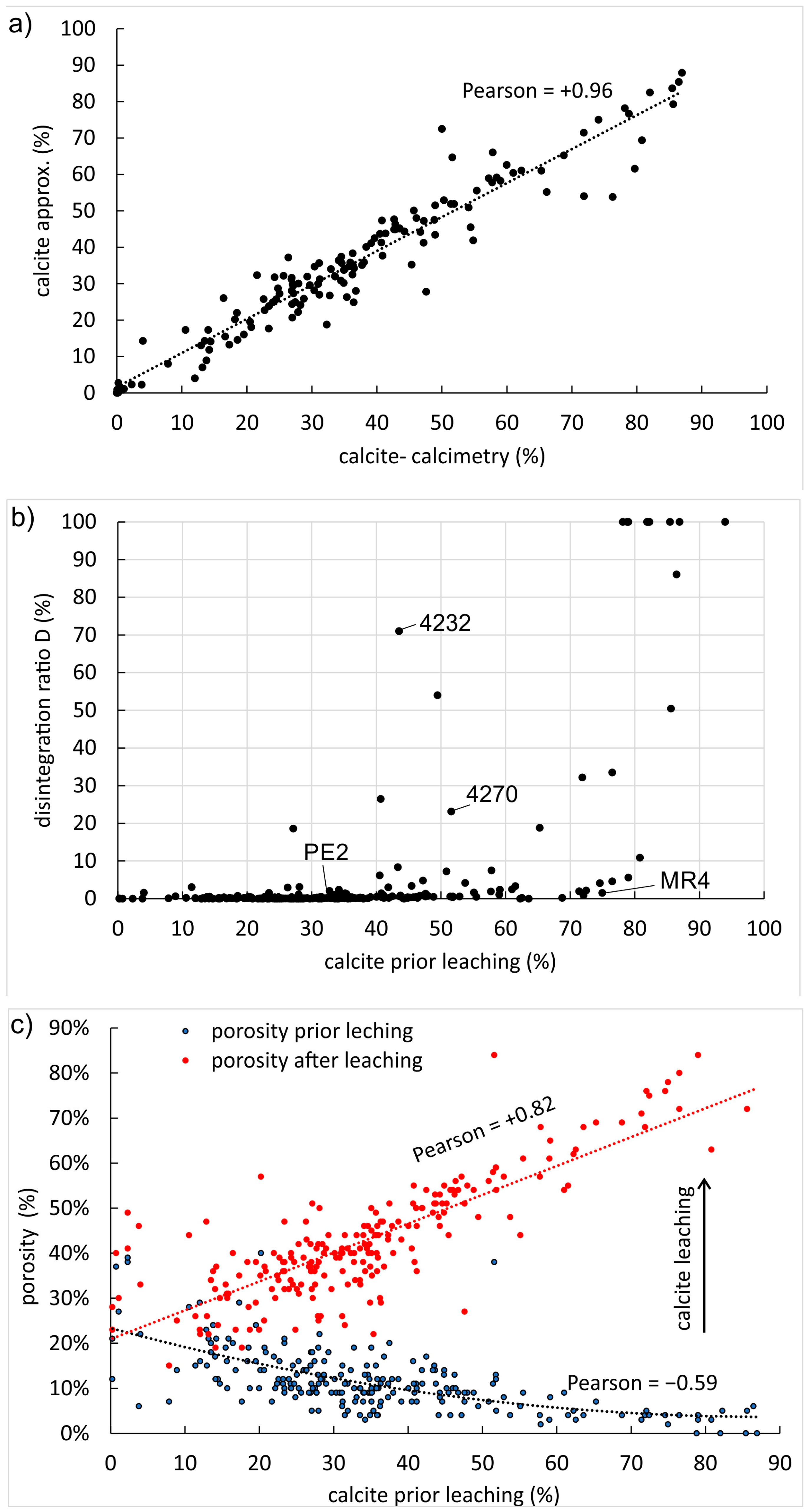
4.1. Carbonate Content, Dissolution Tests, and Porosity
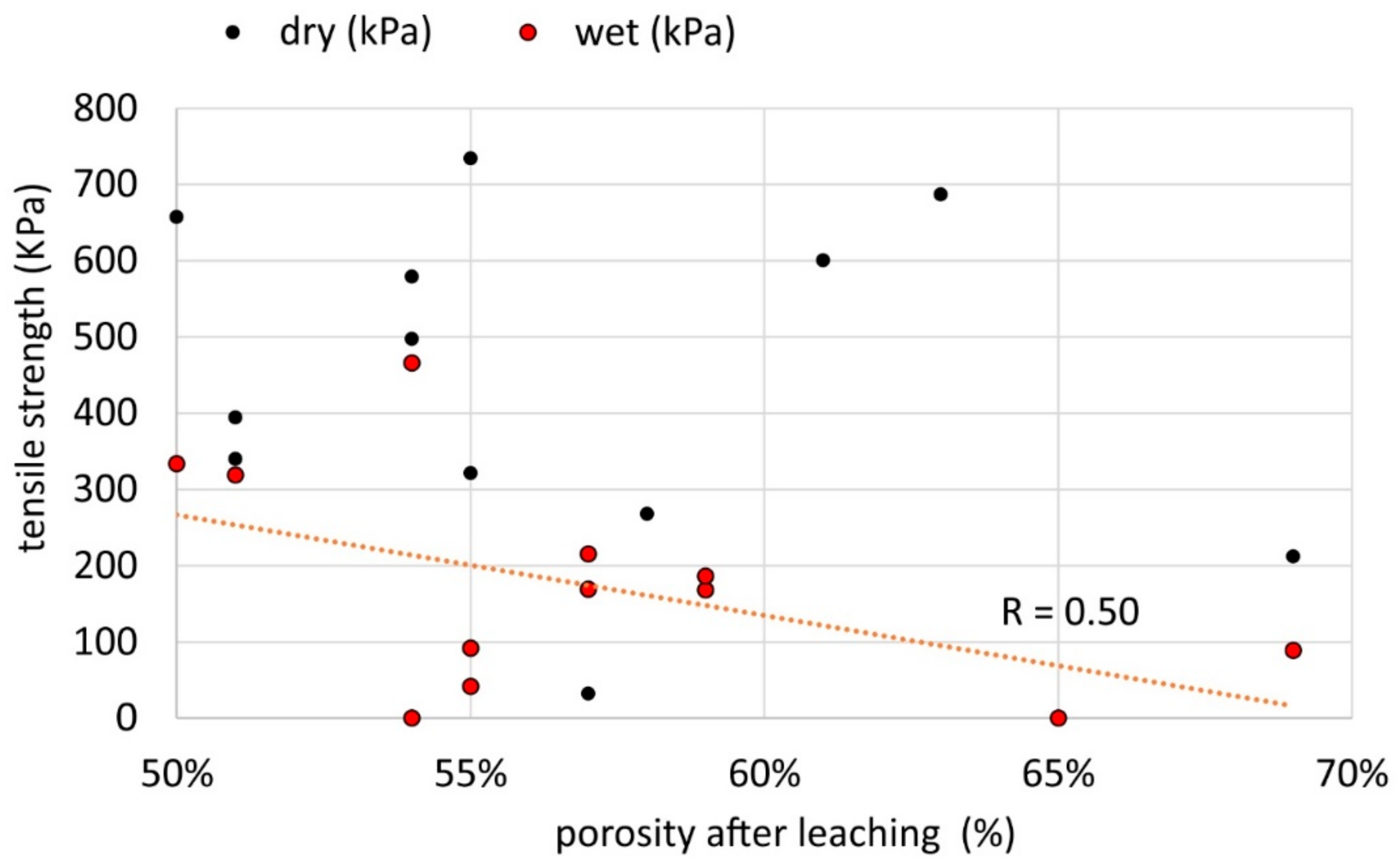
4.2. Disintegration Ratio, Micro-Quartz Cement, and Tensile Strength
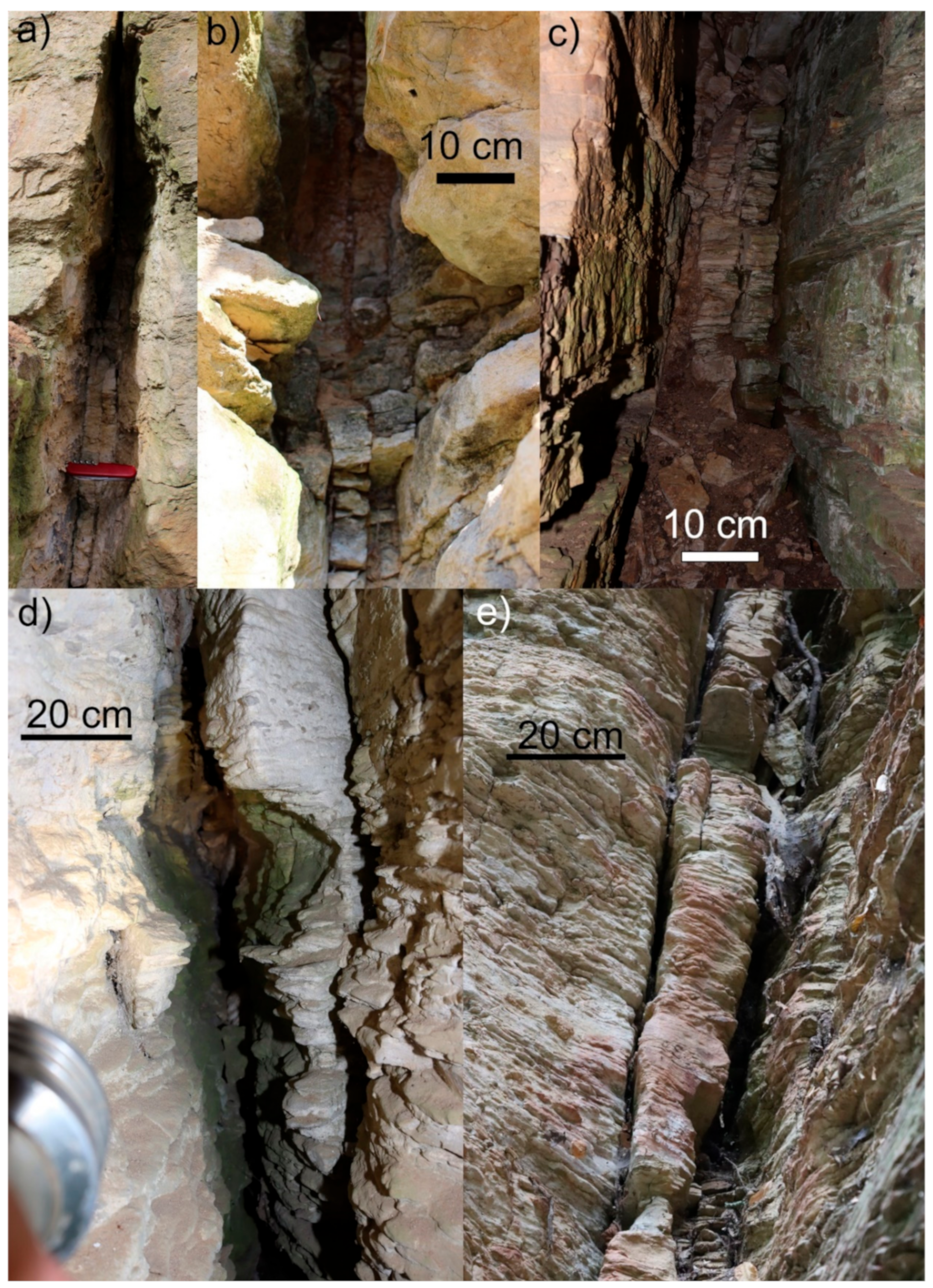
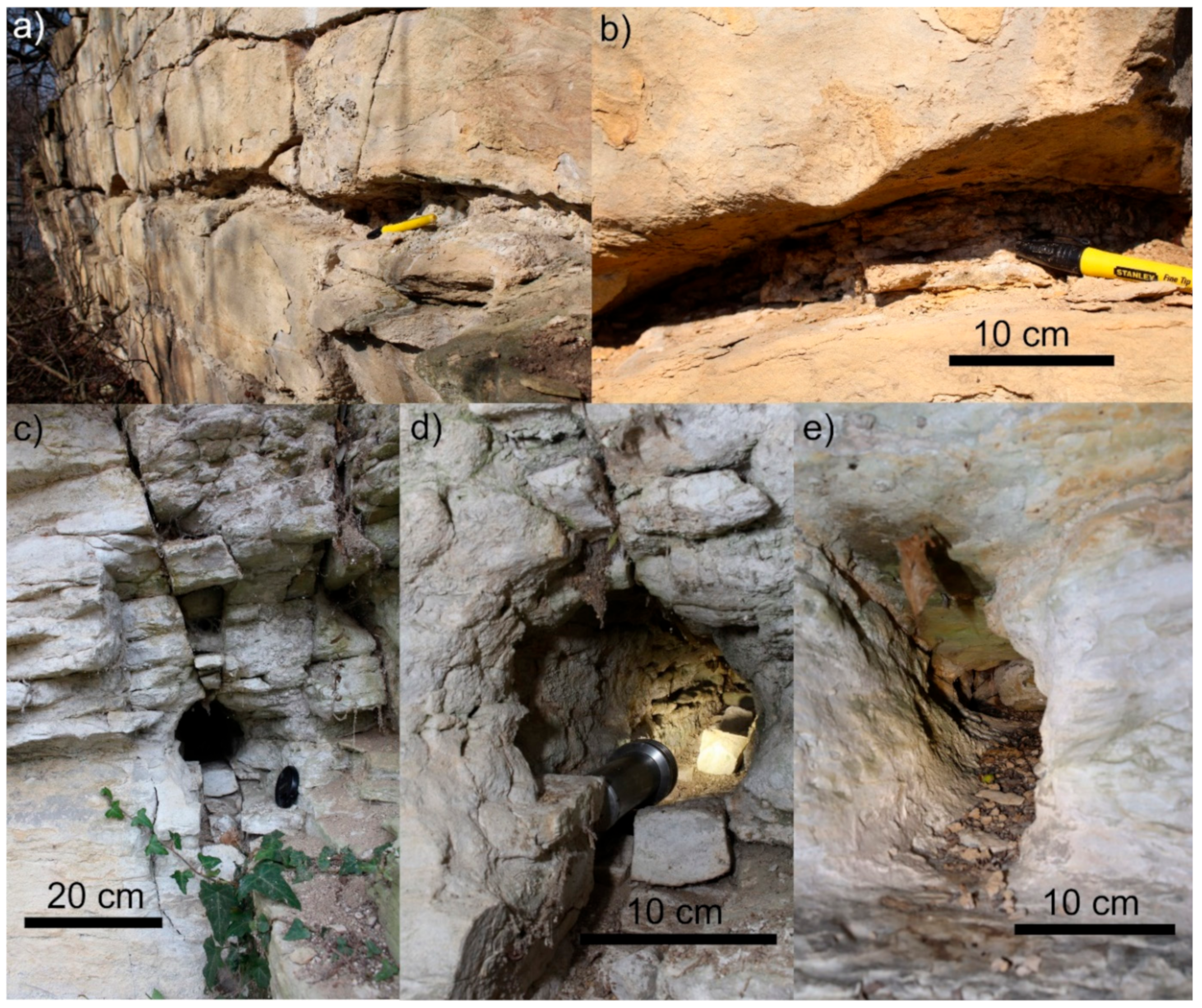
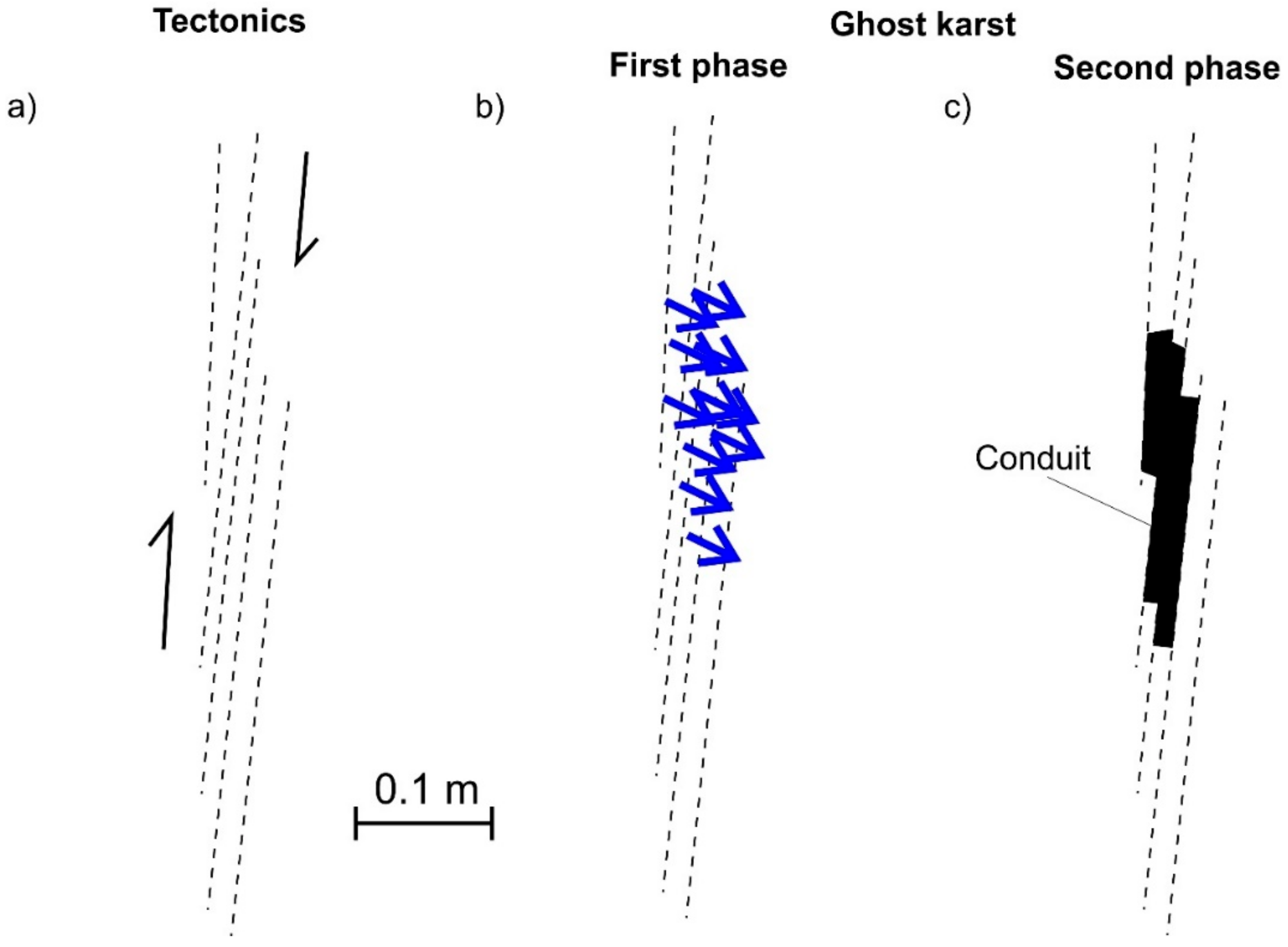
4.3. Characterization of Fracture-Controlled Conduits in Outcrops
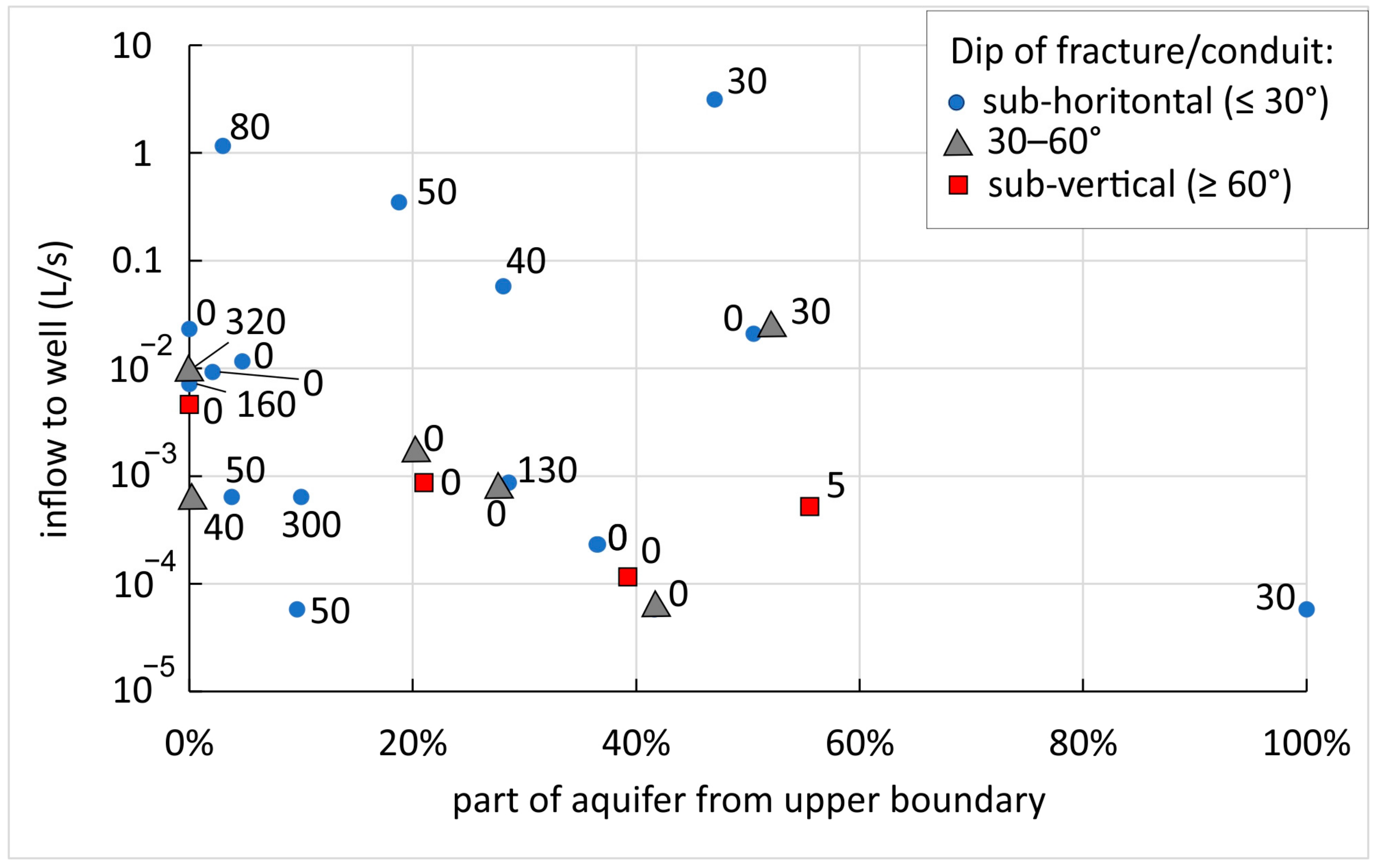
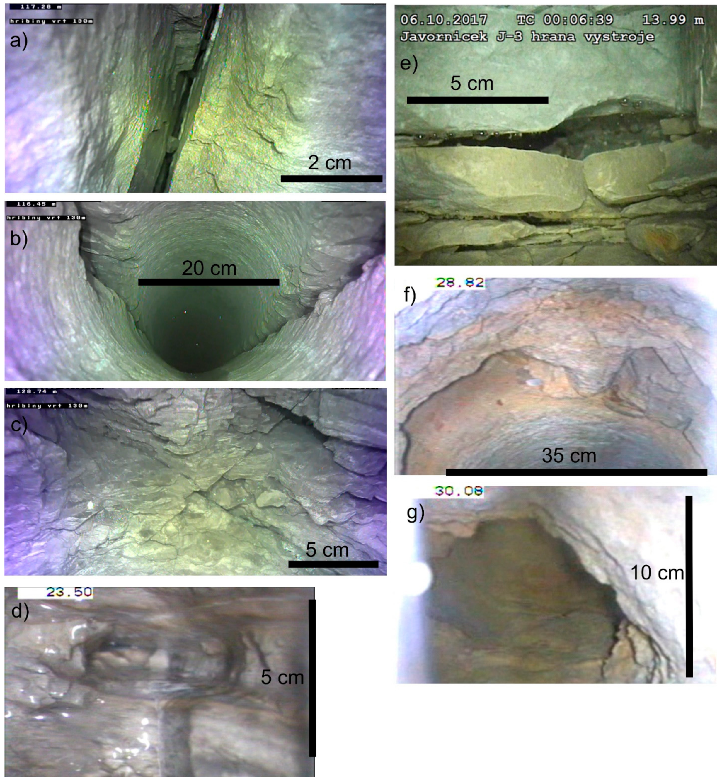
4.4. Characterization of Fracture-Controlled Conduits in Wells Using an Acoustic Televiewer and Downhole Camera
5. Discussion
6. Conclusions
Author Contributions
Funding
Data Availability Statement
Acknowledgments
Conflicts of Interest
References
- Worthington, S.R.H.; Ford, D.C. Self-organized permeability in carbonate aquifers. Ground Water 2009, 47, 326–336. [Google Scholar] [CrossRef] [PubMed]
- Worthington, R.H.; Ford, D.C.; Beddows, P.A. Porosity and permeability enhancement in Unconfined carbonate aquifers as a result of solution. In Speleogenesis, Evolution of Karst Aquifers; Klimchouk, A.B., Ford, D.C., Palmer, A.N., Wolfgang, D., Eds.; NSS: Huntsville, AL, USA, 2000; pp. 77–90. [Google Scholar]
- Florea, L.J.; Vacher, H.L. Springflow hydrographs: Eogenetic vs. telogenetic karst. Ground Water 2006, 44, 352–361. [Google Scholar] [CrossRef]
- Bruthans, J.; Kamas, J.; Filippi, M.; Zare, M.; Mayo, A. Hydrogeology of salt karst under different cap soils and climates (Persian Gulf and Zagros Mts., Iran). Int. J. Speleol. 2017, 46, 303–320. [Google Scholar] [CrossRef]
- Mecchia, M.; Sauro, F.; Piccini, L.; DeWaele, J.; Sanna, L.; Tisato, N.; Lira, J.; Vergara, F. Geochemistry of surface and subsurface waters in quartz-sandstones: Significance for geomorphic evolution of tepui table mountains (Gran Sabana, Venezuela). J. Hydrol. 2014, 511, 117–138. [Google Scholar] [CrossRef]
- Runkel, A.C.; Tipping, R.G.; Alexander, E.C., Jr.; Green, J.A.; Mossler, J.H.; Alexander, S.C. Hydrogeology of the Paleozoic Bedrock in Southeastern Minnesota. In Minnesota Geological Survey Report of Investigations; Minnesota Geological Survey: Saint Paul, MN, USA, 2003; p. 105. [Google Scholar]
- Runkel, A.C.; Tipping, R.G.; Alexander, E.C.; Alexander, S.C. Hydrostratigraphic characterization of intergranular and secondary porosity in part of Cambrian sandstone aquifer system of the cratonic interior of North America: Improving predictability of hydrogeologic properties. Sed. Geol. 2006, 184, 281–304. [Google Scholar] [CrossRef]
- Green, J.A.; Runkel, A.C.; Alexander, E.C. Karst conduit flow in the Cambrian St. Lawrence Confining Unit, southeast Minnesota, USA. Carbonates Evaporites 2012, 27, 167–172. [Google Scholar] [CrossRef]
- Barry, J.D.; Green, J.A.; Steenberg, J.R. Conduit flow in the Cambrian lone rock formation, Southeast Minnesota, USA. In Proceedings of the 14th Sinkhole Conference NCKRI Symposium; Doctor, D.H., Land, L., Stephenson, J.B., Eds.; National Cave & Karst Research Institute: Carlsbad, NM, USA, 2015; Volume 5, pp. 31–41. [Google Scholar]
- Kůrková, I.; Bruthans, J.; Balák, F.; Slavík, M.; Schweigstillová, J.; Bruthansová, J.; Mikuš, P.; Vojtíšek, J.; Grundloch, J. Factors controlling evolution of karst conduits in sandy limestone and calcareous sandstone (Turnov area, Czech Republic). J. Hydrol. 2019, 574, 1062–1073. [Google Scholar] [CrossRef]
- Dubois, C.; Quinif, Y.; Baele, J.M.; Barriquand, L.; Bini, A.; Bruxelles, L.; Dandurand, G.; Havron, C.; Kaufmann, O.; Lans, B.; et al. The process of ghost-rock karstification and its role in the formation of cave systems. Earth-Sci. Rev. 2014, 131, 116–148. [Google Scholar] [CrossRef]
- Hynie, O. Hydrogeology of ČSSR: Ground Waters; Czechoslovak Academy of Sciences: Prague, Czech Republic, 1961. (In Czech) [Google Scholar]
- Pavliš, R. Final Report on Čistá Cl1 and Cl2 well 101 p. Vodní zdroje, Chrudim; Geofond P035952; Vodní Zdroje: Chrudim, Czech Republic, 1981. (In Czech) [Google Scholar]
- Žižka, V. Final Report on Wells Lo 15/4 Pekla and Lo5/3 Choceň-Peliny; Geofond P045435; Vodní Zdroje: Prague, Czech Republic, 1984. (In Czech) [Google Scholar]
- Uličný, D.; Laurin, J.; Čech, S. Controls on clastic sequence geometries in a shallow-marine, transtensional basin: The Bohemian Cretaceous Basin, Czech Republic. Sedimentology 2009, 56, 1077–1114. [Google Scholar] [CrossRef]
- Wiese, F.; Čech, S.; Ekrt, B.; Košťák, M.; Mazuch, M.; Voigt, S. The Upper Turonian of the Bohemian Cretaceous Basin (Czech Republic) exemplified by the Úpohlavy working quarry: Integrated stratigraphy and palaeocenography of a gateway to the Thetys. Cretac. Res. 2004, 25, 329–352. [Google Scholar] [CrossRef]
- Čech, S.; Klein, V.; Kříž, J.; Valečka, J. Revision of the Upper Cretaceous stratigraphy of the Bohemian Cretaceous Basin. Věstník Věstník Ústředního Ústavu Geologického 1980, 55, 277–296. [Google Scholar]
- Štaffen, Z. Chemostratigraphic correlation of beds and formation in Bohemian Cretaceous Basin. Acta Mus. Richnoviensis Sect. Nat. 1999, 6, 7–152. (In Czech) [Google Scholar]
- Skácelová, Z.; Mlčoch, B.; Čech, S. Geological interpretation of a seismic reflection profile in the eastern part of the Bohemian Cretaceous Basin. J. Geosci. 2022, 67, 1–17. [Google Scholar] [CrossRef]
- Burda, J.; Grundloch, J.; Kůrková, I.; Bruthans, J.; Bůzek, F.; Čech, S.; Herčík, F.; Kadlecová, R.; Kondrová, L.; Kůrková, I.; et al. Hydrogeology district 4270. In Evaluation of Groundwater Resources; Final Report; MS Geofond: Prague, Czech Republic, 2016; p. 249. (In Czech) [Google Scholar]
- Pavliš, R.; Tůma, W. Final Report on Hydrogeology Survey in Březová nad Svitavou—Hladové prameny; Vodní Zdroje s.p. Chrudim: Chrudim, Czech Republic, 1983. (In Czech) [Google Scholar]
- Lachman, V. Groundwater Flow and Highly Permeable Zones in Aquifers of Eastern Part of Bohemian Cretaceous Basin based on Litá Area and Surroundings. Ph.D. Thesis, Faculty of Sciences, Charles University, Prague, Czech Republic, 2010; 69p. (In Czech). [Google Scholar]
- Ray, S.; Gault, H.R.; Dodd, C.G. The separation of clay minerals from carbonate rocks. Am. Min. 1957, 42, 681–686. [Google Scholar]
- Bruthans, J.; Světlík, D.; Soukup, J.; Schweigstillová, J.; Válek, J.; Sedlackova, M.; Mayo, A.L. Fast evolving conduits in clay-bonded sandstone: Characterization, erosion processes and significance for origin of sandstone landforms. Geomorphology 2012, 177–178, 178–193. [Google Scholar] [CrossRef]
- Bruthans, J.; Soukup, J.; Vaculíková, J.; Filippi, M.; Schweigstillová, J.; Mayo, A.L.; Mašín, D.; Kletetschka, G.; Řihošek, J. Sandstone landforms shaped by negative feedback between stress and erosion. Nat. Geosci. 2014, 7, 597–601. [Google Scholar] [CrossRef]
- Lin, M.L.; Jeng, F.S.; Tsai, L.S.; Huang, T.H. Wetting weakening of tertiary sandstones-microscopic mechanism. Environ. Geol. 2005, 48, 265–275. [Google Scholar] [CrossRef]
- Pitrák, M.; Mareš, S.; Kobr, M. A simple borehole dilution technique in measuring horizontal ground water flow. Groundwater 2007, 45, 89–92. [Google Scholar] [CrossRef]
- Čáp, P. Microscopic study of the silicified rocks and spongolites of the Bohemian Cretaceous basin. Geosci. Res. Rep. 2006, 39, 107–108. (In Czech) [Google Scholar]
- Gabrielsen, R.H.; Braathen, A. Models of fracture lineaments-joint swarms, fracture corridors and faults in crystalline rocks, and their genetic relations. Tectonophysics 2014, 628, 26–44. [Google Scholar] [CrossRef]
- Kaufmann, O.; Deceuster, J. Detection and mapping of ghost-rock features in the Tournaisis area through geophysical methods—An overview. Geol. Belg. 2014, 17, 17–26. [Google Scholar]
- Rowberry, M.D.; Battiau-Queney, Y.; Walsh, P.; Blazejowski, B.; Boutroumazeilles, V.; Trentesaux, A.; Křížová, L.; Griffits, H. The weathered Carboniferous limestone at Bullslaughter Bay, South Wales: The first example of ghost-rock recorded in the British Isles. Geol. Belg. 2014, 17, 33–42. [Google Scholar]
- Dubois, C.; Quinif, Y.; Baele, J.-M.; Dagrain, F.; Deceuster, J.; Kaufmann, O. The evolution of the mineralogical and petrophysical properties of a weathered limestone in southern Belgium. Geol. Belg. 2014, 17, 1–8. [Google Scholar]
- Medici, G.; West, L.J.; Mounney, N.P. Characterization of a fluvial aquifer at a range of depths and scales: The Triassic St Bees Sandstone Formation, Cumbria, UK. Hydrogeol. J. 2018, 26, 565–591. [Google Scholar] [CrossRef]
- Medici, G.; West, L.J. Review of groundwater flow and contaminant transport modelling approaches for the Sherwood Sandstone aquifer, UK; insights from analogous successions worldwide. Quaterly J. Eng. Geol. Hydrogeol. 2022, 55, qjegh2021-176. [Google Scholar] [CrossRef]
- Meus, P.; Willems, L. Tracer tests to infer the drainage of the multiple porosity aquifer of Luxembourg Sandstone (grand-Duchy of Luxembourg): Implications for drinking water protection. Hydrogeol. J. 2021, 29, 461–480. [Google Scholar] [CrossRef]
- Runkel, A.C.; Tipping, R.G.; Meyer, J.R.; Steenberg, J.R.; Retzler, A.J.; Parker, B.L.; Green, J.A.; Barry, J.D.; Jones, P.M. A multidisciplinary-based conceptual model of a fractured sedimentary bedrock aquitard: Improved prediction of aquitard integrity. Hydrogeol. J. 2018, 26, 2133–2159. [Google Scholar] [CrossRef]
- Dubois, C.; Goderniaux, P.; Deceuster, J.; Poulain, A.; Kaufmann, O. Hydrogeological characterization and modelling of weathered karst aquifers. Applicability to dewatering operations in limestone quarries. Environ. Earth Sci. 2019, 78, 99. [Google Scholar] [CrossRef]


Disclaimer/Publisher’s Note: The statements, opinions and data contained in all publications are solely those of the individual author(s) and contributor(s) and not of MDPI and/or the editor(s). MDPI and/or the editor(s) disclaim responsibility for any injury to people or property resulting from any ideas, methods, instructions or products referred to in the content. |
© 2024 by the authors. Licensee MDPI, Basel, Switzerland. This article is an open access article distributed under the terms and conditions of the Creative Commons Attribution (CC BY) license (https://creativecommons.org/licenses/by/4.0/).
Share and Cite
Starý, J.; Bruthans, J.; Schweigstillová, J.; Mareš, J.; Procházka, M. Origin of Fracture-Controlled Conduits in Calcite-Rich Highly Productive Aquifers Impregnated with Diagenetic Silica. Water 2024, 16, 687. https://doi.org/10.3390/w16050687
Starý J, Bruthans J, Schweigstillová J, Mareš J, Procházka M. Origin of Fracture-Controlled Conduits in Calcite-Rich Highly Productive Aquifers Impregnated with Diagenetic Silica. Water. 2024; 16(5):687. https://doi.org/10.3390/w16050687
Chicago/Turabian StyleStarý, Jiří, Jiří Bruthans, Jana Schweigstillová, Jakub Mareš, and Martin Procházka. 2024. "Origin of Fracture-Controlled Conduits in Calcite-Rich Highly Productive Aquifers Impregnated with Diagenetic Silica" Water 16, no. 5: 687. https://doi.org/10.3390/w16050687
APA StyleStarý, J., Bruthans, J., Schweigstillová, J., Mareš, J., & Procházka, M. (2024). Origin of Fracture-Controlled Conduits in Calcite-Rich Highly Productive Aquifers Impregnated with Diagenetic Silica. Water, 16(5), 687. https://doi.org/10.3390/w16050687