Article

Study on the Transient Flow Characteristics of a Hump Water Pipeline Based on the Random Distribution of Bubbles

1
School of Geomatics and Municipal Engineering, Zhejiang University of Water Resources and Electric Power, Hangzhou 310018, China
2
School of Electric Power, North China University of Water Resources and Hydropower, Zhengzhou 450045, China
3
Engineering Research Center of Digital Twin Basin of Zhejiang Province, Hangzhou 310018, China
4
School of Water Resources and Hydropower, Hebei University of Engineering, Handan 056038, China
5
School of Water Conservancy & Environment Engineering, Zhejiang University of Water Resources and Electric Power, Hangzhou 310018, China
*
Author to whom correspondence should be addressed.
Water 2023, 15(21), 3831; https://doi.org/10.3390/w15213831
Submission received: 17 September 2023 / Revised: 27 October 2023 / Accepted: 31 October 2023 / Published: 2 November 2023
(This article belongs to the Special Issue Advances in Hydrodynamics of Water Pump Station System)

Abstract

:
Aiming at establishing the transient flow characteristics of gas–liquid two-phase flow in high-undulation water pipelines, based on the bubble distribution law measured using physical tests, the bubble distribution law function was input into the hump-pipe fluid domain model, and CFD numerical simulation was carried out for different flow rates and different air contents. The CLSVOF two-phase flow model and the RNG k-ε turbulence model were used to analyze the flow pattern evolution and pressure pulsation propagation in the process of gas–liquid two-phase flow through a hump pipe. The results show that the bubble size has a lognormal distribution, the equivalent diameter is between 3 mm and 10 mm, and the evolution of the flow pattern in the hump pipe is complex and violent. In the horizontal pipe section, there are three main flow patterns: bubble flow, wavy flow and segment plug flow. In the vertical pipe, there are two main flow patterns, slug flow and churning flow, and the flow pattern is affected by the flow rate and the air content rate. When air bubbles or air pockets in the pipeline flow through a certain area, this leads to a steep increase and decrease in the pressure pulsation amplitude in the region, and the pressure fluctuation is extremely frequent. Compared with the water flow rate, the air content is the main factor affecting the relative pressure pulsation amplitude under the condition of a 0.15-air content operating mode, which is generally approximately two to six times that of the 0-air content operating mode. The results of the research should facilitate the prediction of stagnant gas pipeline system bursts and water hammer protection, providing a theoretical basis and calculation parameters.

1. Introduction

Large-scale water-resource allocation projects often have the characteristics of large fluctuations and many operating conditions, their operating safety requirements are extremely high, and stagnant gas poses a threat to the safe operation of the project, representing one of the major potential risks [1]. In pressurized water pipelines, pumps and other mechanical equipment, bubbles can reach 5–10% of the volume of water, and undulating sections of pipelines usually have a higher air content, which accumulates to form stagnant air pockets [2,3]. Stagnant air pockets not only reduce the effective water cross-section, but also reduce the system’s water transfer capacity, while at the end of the pipeline, if a valve closes quickly when stagnant gas is present, the pipe may burst, leading to water supply interruption and other serious accidents [4].
The motion characteristics of bubbles with water flow are key to studying the mechanism of stagnant gas in complex water-resource pressurized pipeline transportation systems [5]. In order to reduce the risk of pipe bursts in pipeline stagnation, many scholars have conducted a lot of research based on the bubble distribution model. In the bubble distribution model, using the gas–liquid two-phase transient flow in pressurized pipelines from the 1960s, there are two main computational models: the bubble uniform distribution model and the bubble discrete model [6]. Kranenburg et al. [7] proposed a bubble uniform distribution model in which bubbles are uniformly distributed throughout the entire region and the pressure pipeline liquid flow is divided into three regions. In the transient flow calculation process, the water-hammer wave velocity should be calculated according to the change in pressure and cavitation rate. Brown et al. [8] proposed a discrete model which considers that the bubbles are centrally distributed in each calculation section of the pipeline, the expansion law of each bubble with the change in pressure conforms to the perfect gas equation of state, there is no gas in the pipeline liquid between the two bubble cross-sections and the water-hammer wave velocity is constant. However, in reality, the distribution of bubbles in the pipeline is based on random distribution, so the use of discrete and uniform distribution models based on centralized distribution for calculation is bound to cause large errors in the calculation results [9,10]. Yang et al. [11,12] concluded that air is non-uniformly distributed in the pipeline, the position of bubbles is a variable that changes with time, only a portion of the pipeline has bubbles at any instant, and the pipeline with bubbles has a larger cavitation rate. In the physical test of bubble distribution, Tokuhiro [13] and others obtained the required flow field parameters using a CCD camera and workstation processing under laser irradiation and measured the trajectory and morphology change rule of bubbles. SRA et al. [14] photographed and processed the stagnant gas phenomenon in the pipeline and established the generation law and movement state of stagnant gas in the pressurized pipeline. Wan et al. [15] designed a physical test model with several consecutive bends and concluded through a large number of tests that an appropriate reduction in the inclination angle of the pipeline and an increase in the flow rate can effectively discharge the stagnant gas mass in the pipeline. Jansson et al. [16] studied a pipeline water hammer with column separation in a flow range through physical tests. The results showed that there was no obvious separation interface; the boundary was composed of dispersed small bubbles mixed with a larger steam structure, in which the bubbles seemed to become smaller after each rupture. Urbanowicz et al. [17] modified the discrete bubble cavity model (DBCM); the comparisons between computed and measured results showed that the influence of delayed strain is far greater than unsteady friction on pressure wave damping. Based on physical tests, He et al. [18] discussed the related changes in metal surface morphology through weightlessness and the cavitation erosion rate; the results showed that a reasonable surface morphology can inhibit cavitation erosion. Veisi et al. [19] designed a metering system for measuring liquid voidage and verified the accuracy of the system through the physical test of water–air two-phase annular flow. By analyzing the probability density function of dynamic pressure and the results of fast Fourier transform analysis, Khan et al. [20] proposed a new method to identify the flow pattern in horizontal pipes.
Combinations of CFD numerical simulation and physical tests are often used to study water–gas two-phase flow patterns [21]. According to the appearance of the shape of the fluid and the distribution characteristics of the gas phase, the horizontal pipeline gas–liquid two-phase flow pattern can be divided into six kinds: bubble flow, plug flow, laminar flow, wavy flow, slug flow and annular flow. The vertical pipeline gas–liquid two-phase flow pattern can be divided into five kinds: bubble flow, slug flow, churning flow, annular flow and thin-beam annular flow. A flow category schematic diagram is shown in Figure 1 [22,23].
The water–gas two-phase flow pattern in the pipeline is mainly affected by the water–gas-phase flow rate, fluid physical parameters, pipe diameter and inclination and other factors, and for undulating pipelines, common stagnant parts mainly include the raised point in the pipeline, the horizontal pipe section and the downward inclined pipe section [24,25]. Based on the experimental test and numerical analysis, considering the basic dynamics of air–water interaction in unventilated pipes, Ramos, H.M. et al. [26] predicted air exchange through any installed valve and their roles in changing the system behavior during unsteady flow. Feng et al. [27] used the VOF two-phase flow model to conduct transient simulations of gas–liquid flow in a pipeline, explored the changes between flow patterns, and found that the water-phase integral number of the pipeline undergoes three periods of linear growth, irregular growth and no further growth due to the water-phase integral number of the pipeline. Wang et al. [28] performed numerical simulations and physical tests on a 90-degree gas–liquid elbow based on the VOF model and explored the effects of the flow pattern evolution on the pressure distribution, velocity distribution and air content of the cross-section. Compared with the VOF model alone, Yu et al. [29] used the VOSET method to simulate the characteristics of the gas–liquid flow pattern in a vertically ascending circular pipe, and the results show that the VOSET method not only maintains the conservation of the mass of the gas–liquid flow, but also discretizes the surface tension more efficiently, and the simulation results are more accurate and effective. Bourlioux et al. [30] proposed a CLSVOF (Coupled Level Set and Volume of Fluid) method, which solved the problems of mass non-conservation in the transport process of the Level Set method and discontinuity at the phase interface of the VOF model. Yang [31] used the CLSVOF method to study the effects of different flow rates, inclination angles, pipe diameters and other comprehensive factors on the critical flow rate of bubble initiation in gas–liquid two-phase flow, and the empirical formulas for the calculation of the critical flow rate of bubble initiation in three kinds of pipes, namely, horizontal, inclined and vertical pipes, were obtained after computational analysis and were completely matched with the physical experiments. Shang et al. [32] used a CLSVOF model to calculate the critical flow rate for gas–liquid two-phase flow in a vertical pipe. A numerical simulation of gas–liquid two-phase flow was carried out, and more accurate data than the VOF model were obtained by comparing them with physical tests. Tang et al. [33] studied the cavitation flow in the pipeline based on the computational fluid dynamics (CFD) method of Fluent 2020R2 software and successfully captured the formation, development and collapse process of cavitation bubbles.
In summary, the distribution of bubbles in pressurized water pipelines, the bubble morphology and pipeline layout, the water flow rate and other dynamic and static multiparameter coupling relationships reflecting the complexity of the pipeline system containing gas flow lead to bubble aggregation, airbag retention and air mass generation. The lack of fine experimental observations of the risk of stagnant gas in different sections of pipes demonstrates that the dynamic identification of these risks is difficult.
The current research on water–liquid two-phase flow in pipelines is mainly carried out under the assumption that bubbles are discretely and uniformly distributed, while in fact bubbles are randomly distributed in the pipeline, and such assumptions will inevitably lead to large errors in the calculation results. In addition, the gas–liquid flow through a highly undulating pipe is a complex transient process, and so it is necessary to consider a larger range of water–gas two-phase volume fractions so as to explore the flow pattern evolution and pressure pulsation propagation law in the pipe.
Therefore, a vertically undulating hump pipe is taken as the research object in this paper; firstly, the bubble random distribution model of the pressurized pipeline is established through physical tests, and then, based on the CLSVOF model and the RNG k-ε turbulence model, the typical flow rate and air content as physical variables are used for physical tests and numerical simulations so as to reveal the effect of bubble random distribution on the flow pattern and the pressure pulsation in the long pressurized pipeline system. The research results can provide theoretical support for the risk analysis of stagnant gas bursting in pressurized pipeline systems, improve the theory of the two-phase transient flow of water and gas in pressurized pipelines, and provide computational parameters for the safe and stable operation of the project.

2. Physical Tests of Gas–Liquid Two-Phase Pipe Flow

2.1. Test Platform

Figure 2 shows the system layout of the water–air flow test platform. The test system is mainly composed of a water supply system, a gas supply system and a data acquisition system.
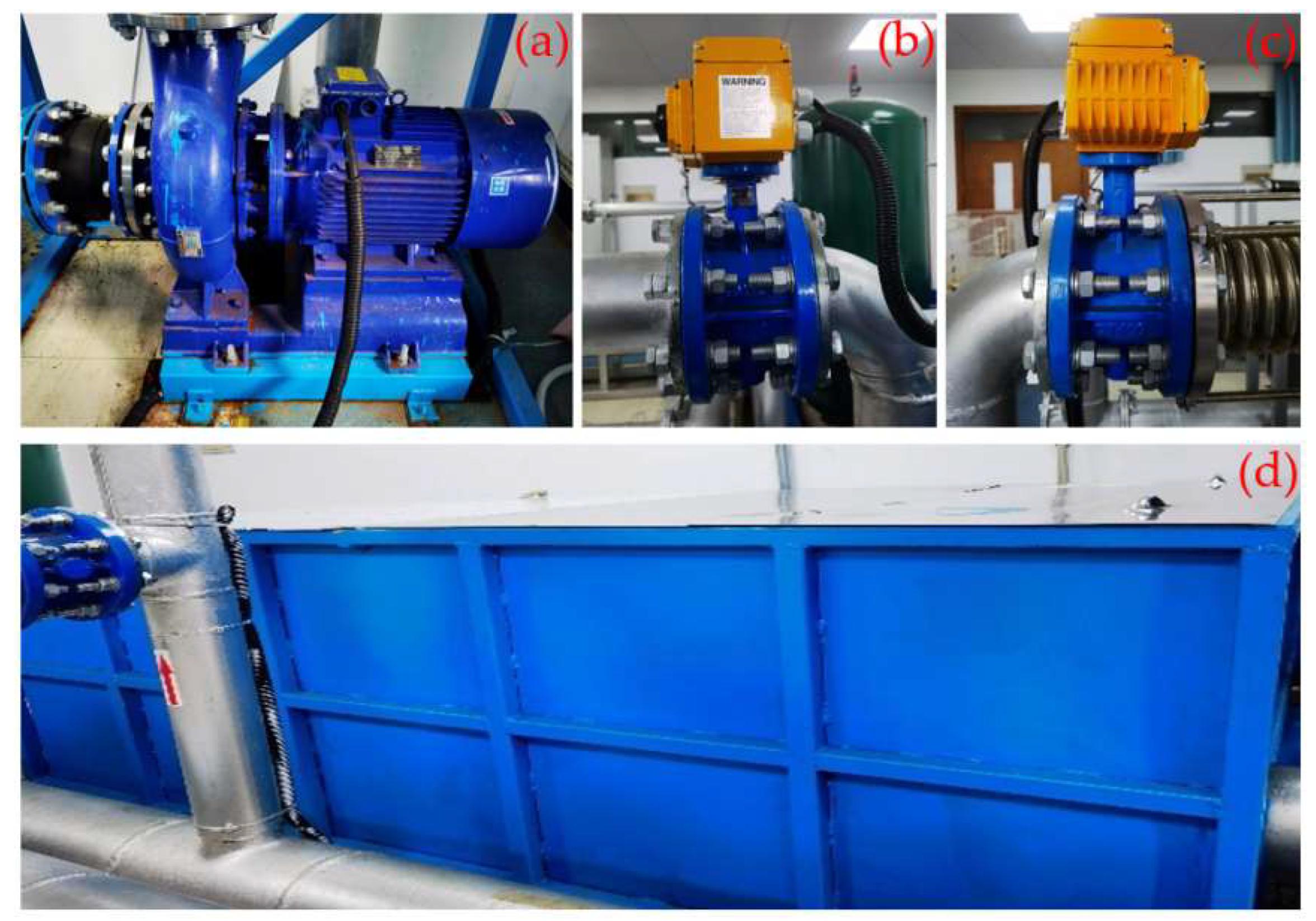
The water supply module mainly consisted of a low-level water tank, a horizontal centrifugal pump, pressurized pipelines and an electric control valve. The test selected the pressurized flow water supply mode by adjusting the centrifugal pump frequency to realize different flow rate operating modes. The characteristic parameters of the pump are shown in Table 1, and physical pictures of the relevant devices of the water supply module are shown in Figure 3.
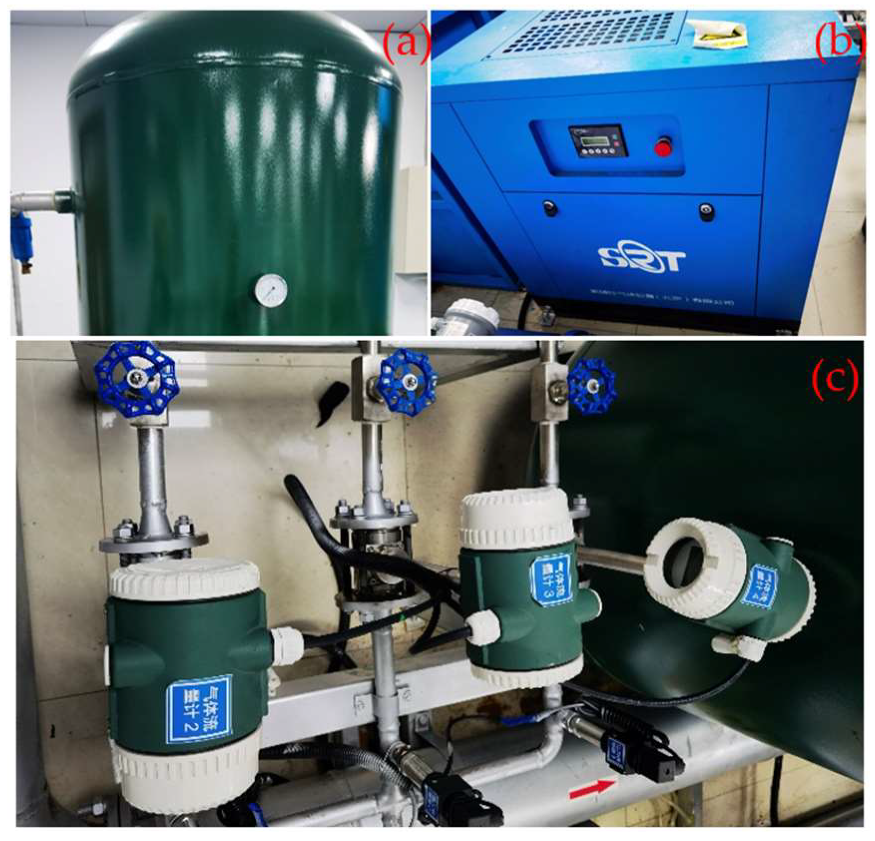
As shown in Figure 4, the gas supply module mainly consisted of an air storage tank, an air compressor and a vortex gas flow meter. The volume of the air storage tank was 600 L, and the maximum pressure value was 1 MPa. The maximum pressure of the air compressor was 8~10 bar, the maximum exhaust volume was 1000 L/min and air cooling was used. In order to improve the input gas flow accuracy control requirements, three groups of parallel pipelines were set up, and each group of pipelines were set up with a valve and a vortex gas flow meter, which could be used to control the gas flow rate according to the selection of different gas delivery pipelines and the setting of valve openings to control the size of the gas mass in the input pipeline.
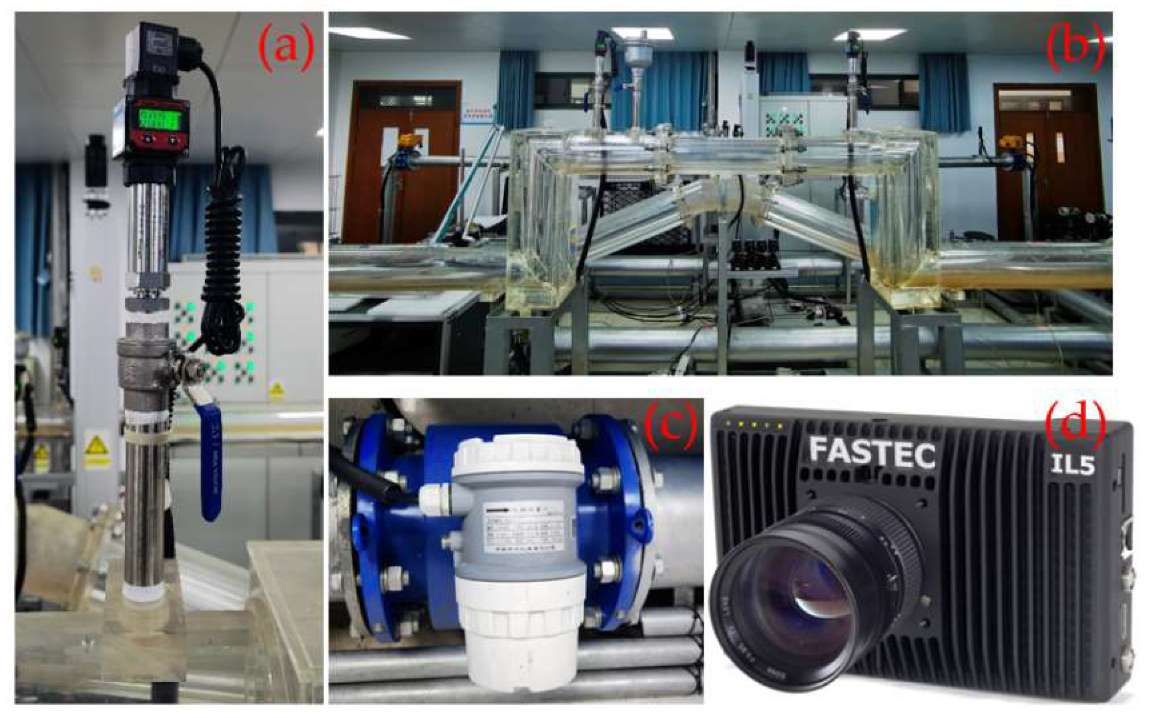
As shown in Figure 5, the data acquisition module was mainly composed of a DN100 hump pipe, an electromagnetic flowmeter, a pressure sensor, a high-speed camera image acquisition system and a complementary light meter. The DN100 hump-pipe section consisted of transparent plexiglass. The electromagnetic flowmeter used an MGG/KL type electromagnetic sensor to monitor the volume flow of water in the pipeline (with a flow rate measurement range of 0~15 m/s, a basic error of ±3% R (R represents rounding error) and a flow rate accuracy of 0.5%); in order to prevent the air mass in the pipeline from interfering with the accurate reading of the electromagnetic flowmeter, the electromagnetic flowmeter was located 10 m in front of the gas injection point. The model of pressure sensor is HR3202, the sensing range is −0.1~1.0 MPa, the accuracy is 0.5% FS (full scale) and the output current signal is 4~20 mA; this type of pressure sensor can continuously and accurately measure the pressure of gas, liquid and steam and has the advantages of high measurement accuracy and good working stability. The high-speed camera model FASTEC IL5, with a built-in 12-bit CMOS sensor and with Full SXGA 1024P shooting, could reach 668FPS, with a high-speed camera shutter speed of 3 μs to 41.654 ms, allowing image acquisition at high acquisition frequencies. In this study, the combination of a Pixel-p45c supplementary light lamp and an ordinary LED lamp was used to provide the required brightness for high-speed cameras. The color temperature of the Pixel-p45c supplementary light lamp could be adjusted between 3000 K and 5400 K, providing high color rendering and stability.

2.2. Test Program

The test mainly aimed to study the random distribution of bubbles in the pump pressurized aqueduct and its effects on the two-phase transient flow characteristics of water and gas for different air contents and different flow rates within a DN100 right-angle elbow test section for two-phase water and gas transient flow research. First of all, the image acquisition and data acquisition systems were used to record the results for the random distribution of bubbles in the test section, providing the experimental basis for the model for the numerical simulation of the random distribution of bubbles. Then, we identified and classified the changes in the two-phase flow pattern and analyzed the effects of the random distribution of bubbles in the pressurized pipe on the water transfer process according to the measured pressure signal.
In engineering applications, the water filling rate is generally between 0.6 and 3.0 m/s, while the pressurized aqueduct system air content should be 5–10%, and undulating sections of pipes usually have a higher air content [2,34]. Therefore, three inlet flow rates of 1.0 m/s, 1.5 m/s and 2.0 m/s were selected for the test program, and four air content operating modes were chosen, namely, air-phase volume fractions of 0 (no air), 0.05, 0.10 and 0.15, and the specific operating modes of the test are shown in Table 2.
After the test of one working condition was finished, we slowly increased the frequency of the water pump to 15 Hz and flushed the residual bubbles of the previous working condition out of the test pipe section. We repeated the same working condition 3 times to ensure the correctness of the test and then carried out the test under other working conditions.

2.3. Image Analysis of the Random Distribution of Bubbles

As shown in Figure 6, in order to obtain the accurate random distribution of bubbles, the image acquisition system and data acquisition system were used to observe the morphology, size and distribution of bubbles with different air contents in the horizontal pipe section through the image processing methods of image gray scaling, image binarization and hole filling. It was concluded that the bubble size follows a lognormal distribution law; that the equivalent diameter is between 3 mm and 10 mm; that the higher the air content, the more obvious the phenomenon of small bubbles aggregating to generate large bubbles; that the distribution of bubbles is random; and that the relationship between the bubble size and the distribution of bubbles is random. The results for the distribution of bubbles are shown in Figure 7.

3. CFD Numerical Simulation

3.1. Hydraulic Model and Meshing

As shown in Figure 8, a three-dimensional fluid model was established, which was the same as the one used for the physical test. The test pipe section is a hump pipe with a pipe diameter of 0.1 m. The test pipe section is divided into five segments: the first one is the front horizontal section with a length of 1 m; the second one is the vertical rising section with a length of 0.3 m; the third one is the middle horizontal section with a length of 1.15 m; the fourth one is the vertical descending section with a length of 0.3 m; and the fifth one is the rear horizontal section with a length of 1 m. The pressure in the pipe is analyzed through the monitoring points at P1, P2, P3 and P4, with the change in pressure with time.
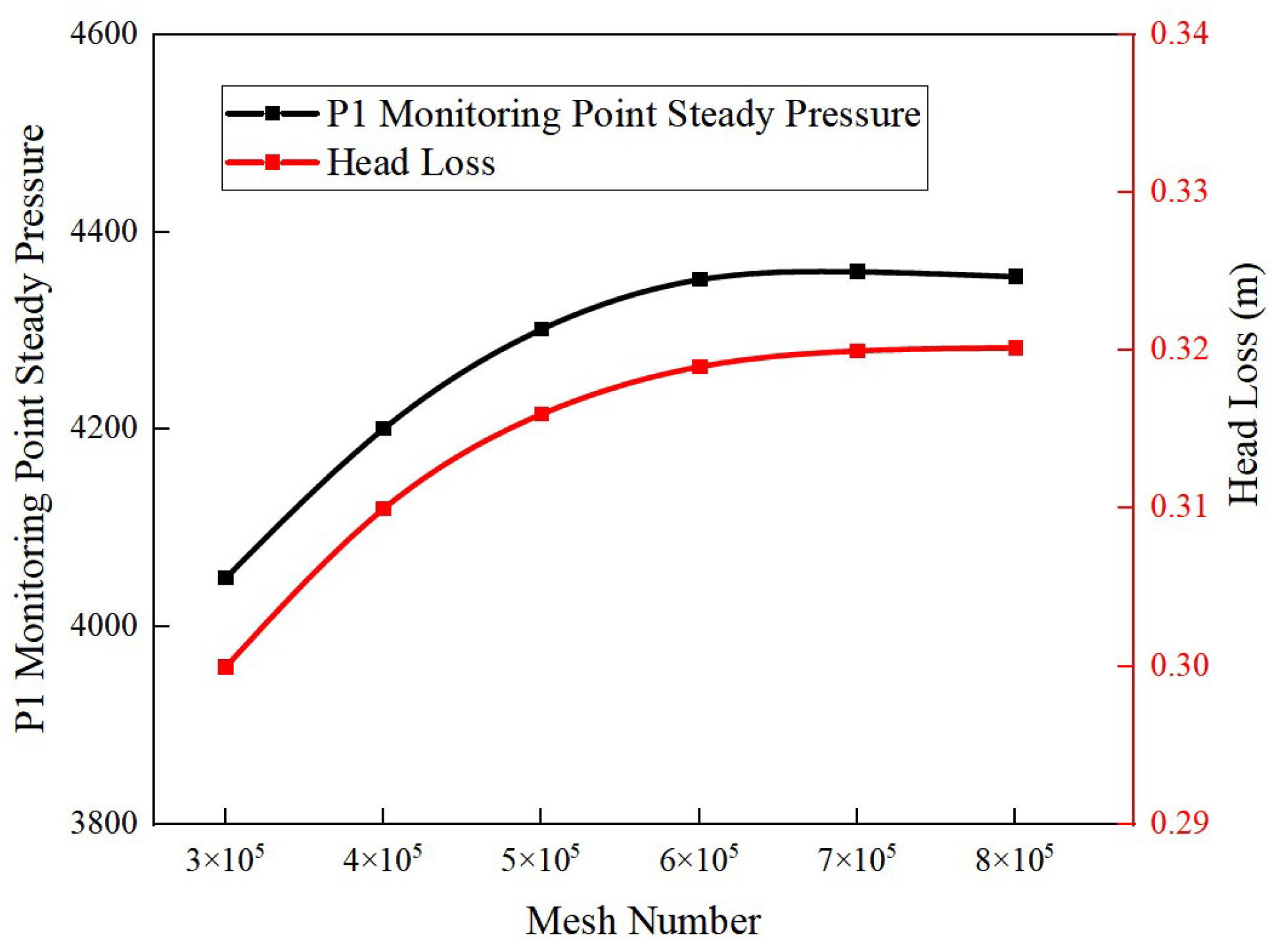
The software Fluent Meshing was used to mesh the model, an unstructured tetrahedral mesh was used for the whole flow channel, different local mesh scales were set to control the total number of meshes, the boundary layer was locally encrypted at the right-angled turn, the mesh independence was verified according to the steady-state pressure and head loss at point P1, and the final mesh delineation results are shown in Figure 9, with a total number of cells of 700,000 meshes. The minimum grid orthogonal quality was 0.45, and the grid independent verification results are shown in Figure 10.

3.2. Numerical Simulation Methods

3.2.1. VOF Multiphase Flow Model

The VOF model [35] can simulate multiphase flow by tracking the volume fraction of each fluid, which is able to effectively track the trajectory of bubbles in the pipeline and changes in bubble morphology. This study focuses on the non-constant flow characteristics in the water transfer process and does not involve the law of conservation of energy, which is controlled by the following equations:
The continuity equation:
( α q ρ q ) t + · ( α q ρ q v q ) = 0
where α q is the q fluid volume fraction of the phase; ρ q is the fluid volume fraction of the first phase q fluid density of the phase; t represents time; and v q is the velocity of the q phase.
In VOF, the volume fraction of each phase satisfies:
q = 1 n α q = 1
The momentum equation:
( ρ v ) t + · ( ρ v ) = p + · [ μ ( v + v T ) ] + ρ g + F
where ρ is the volume-weighted average density; v is the mixing velocity; p is the pressure; μ is the volume-weighted average viscosity; g is the gravity acceleration; and F is the surface tension.
Among these,
ρ = α l ρ l + α g ρ g
μ = α l μ l + α g μ g
where α l and α g denote the liquid-phase volume fraction and the gas-phase volume fraction, respectively; ρ l and ρ g denote the liquid-phase density and the gas-phase density, respectively; and μ l and μ g denote the liquid-phase viscosity and the gas-phase viscosity, respectively.
The continuous surface force model is used to simulate the surface tension of the gas–liquid interface, and the surface tension is added to Equation (3) as a source term [28].
F = σ 2 ρ k 1 ( s 1 ) ρ l + ρ g
k 1 = · n 1
where σ is the surface tension coefficient; k 1 is the surface curvature; s 1 is the surface normal vector at the interface; and n 1 is the unit normal vector.

3.2.2. RNG k-ε Turbulence Model

The flow pattern of the hump pipe is curved water with large curvature, which is fully developed turbulence with a high Reynolds number, so the RNG k-ε turbulence model with good simulation accuracy was chosen [36]. The turbulent kinetic energy ( k ) equation and turbulent dissipation rate ( ε ) equation are as follows:
( ρ k ) t + ( ρ k u i ) x i = x j [ α k μ e f f k x j ] + G k + G b ρ ε Y M + S k
( ρ ε ) t + ( ρ ε u i ) x i = x j [ α ε μ e f f ε x j ] + G 1 ε ε k ( G k + G 3 ε G b ) + G 2 ε ρ ε 2 k R ε + S ε
η = S k ε
S = 2 S i j · S i j
S i j = 1 2 ( u i x j + u j x i )
where α k and α ε correspond to the reciprocal of the effective turbulence Prandtl number for α and ε, respectively, with the default values of α k = 1.39 and α ε = 1.39; G k is the production term for the turbulent kinetic energy (k) due to the mean velocity gradient; G b is the production term for the turbulent kinetic energy (k) due to buoyancy effects; Y M is the pulsating expansion term; C 1 ε , C 2 ε and C 3 ε are empirical constants, taken as 1.42, 1.68 and 0.09, respectively (the default values in the Fluent calculation software were adopted); and S k and S ε are user-defined source terms (a source term represents an unstable term that cannot be included in the control equation). In general, a source term is not constant, and the default source term of Fluent software was adopted in this paper.

3.3. Boundary Conditions and Solution Settings

3.3.1. Boundary Conditions

The inlet boundary condition was set as the inlet velocity, at 1.0 m/s, 1.5 m/s and 2.0 m/s. The outlet pressure was set as a standard atmospheric pressure, and the air content in the inlet front end area was 0, 0.05, 0.10 and 0.15. The numerical simulation conditions were the same as the physical test conditions, and the specific calculation conditions are shown in Table 2. The fluid medium in the pipeline was water and air, and the specific physical properties of the two phases of water and gas are shown in Table 3.
The input of bubbles was based on the numerical simulation of constant flow by converting the equivalent diameters of the experimentally obtained bubbles and uniformly inputting circular bubbles to serve as initial conditions. In this paper, the radius of the bubble was programmed with a lognormal distribution by constraining the total volume of the bubble according to the mean and variance of the bubble size obtained from the experimental data, then by defining the distance between the location of the bubble and the center of the axis, and finally by varying the two parameters of the circular centroid and the radius, with some of the conditions shown in Equation (13).
p ( θ ) ( x ( θ ) y ( θ ) ) = r ( cos θ sin θ ) + ( x 0 y 0 )               θ [   0 ,   2 π   ]
where (x0, y0) denotes the coordinates of the center of the bubble and r is the radius of the bubble.

3.3.2. Solution Setup

The numerical simulation was solved using Fluet 2020 R2 software, the coupled constant calculation of pressure and velocity was performed using the SIMPLEC algorithm, the non-constant calculation was performed using the PISO algorithm, the momentum and turbulent kinetic energy dissipation rate were discretized using the second-order windward format, the solid wall was set to a non-slip wall, and the accuracy of residual convergence was set to 10−5. In order to facilitate the calculation of the curvature of the phase interface, the normal vector, the surface tension and other parameters, the CLSVOF coupled model was used. Firstly, the constant flow calculation without bubble input was carried out, and the random distribution of bubbles program was input into the front horizontal 0–0.5 m pipe section through the Journal file. Taking the air content rate of the 0.15 operating mode as an example, the distribution of bubbles after completing the input of bubbles is shown in Figure 11; the fixed time step (Δt) was set to 0.001 s, and the total computation time was 5 s.

4. Results and Analysis

4.1. Validation of the Numerical Simulation Results

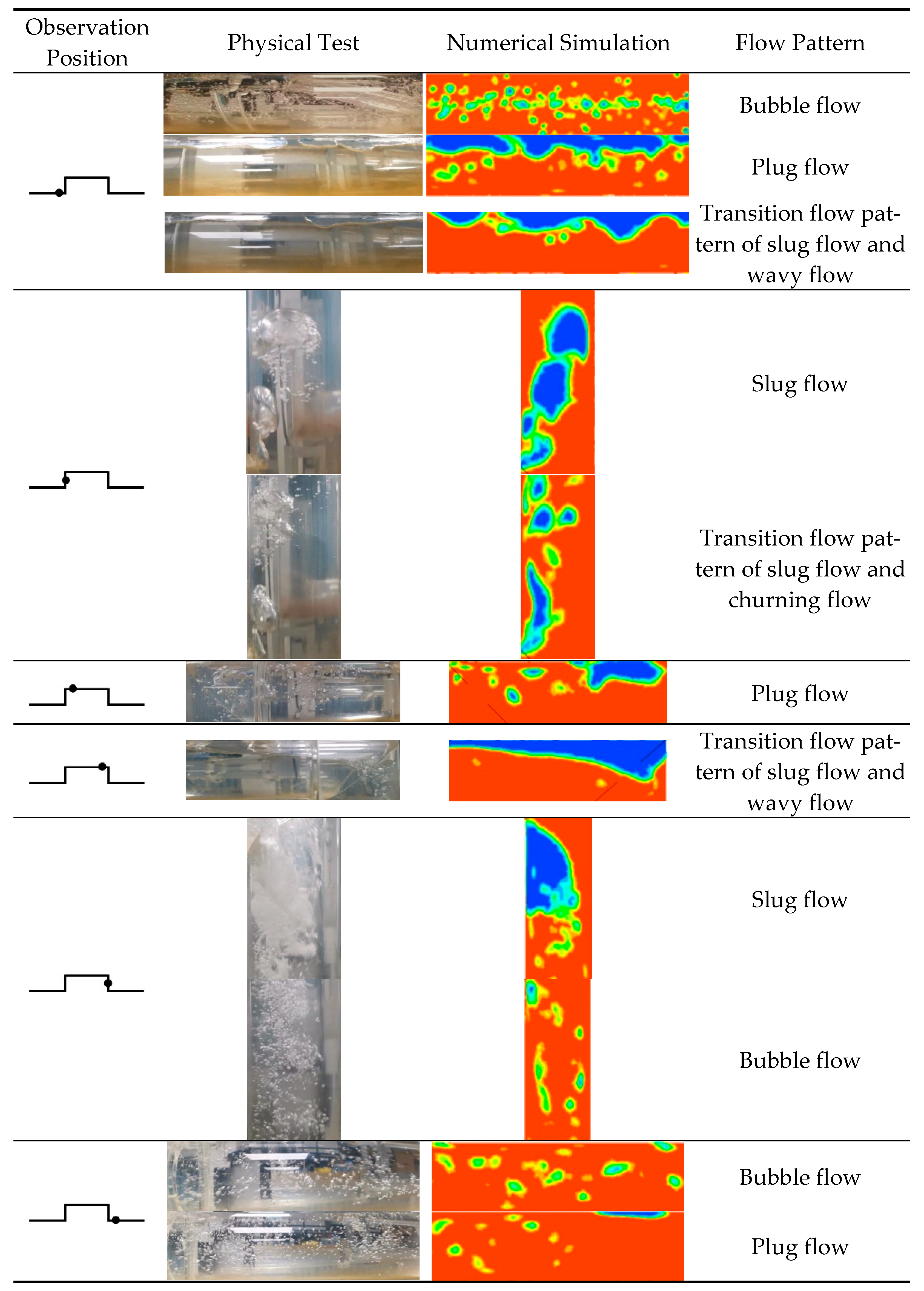
In order to verify the accuracy of the numerical simulation calculations, it is necessary to compare and analyze the flow pattern changes in the pipe; in order to avoid redundancy in this article, the following is a comparison of the flow pattern changes in Case 12 (2.0 m/s, 0.15 air content), as shown in Figure 12. The flow pattern of the whole flow process changes into bubble flow–wavy flow–slug flow–churning flow–bubble flow–plug flow.
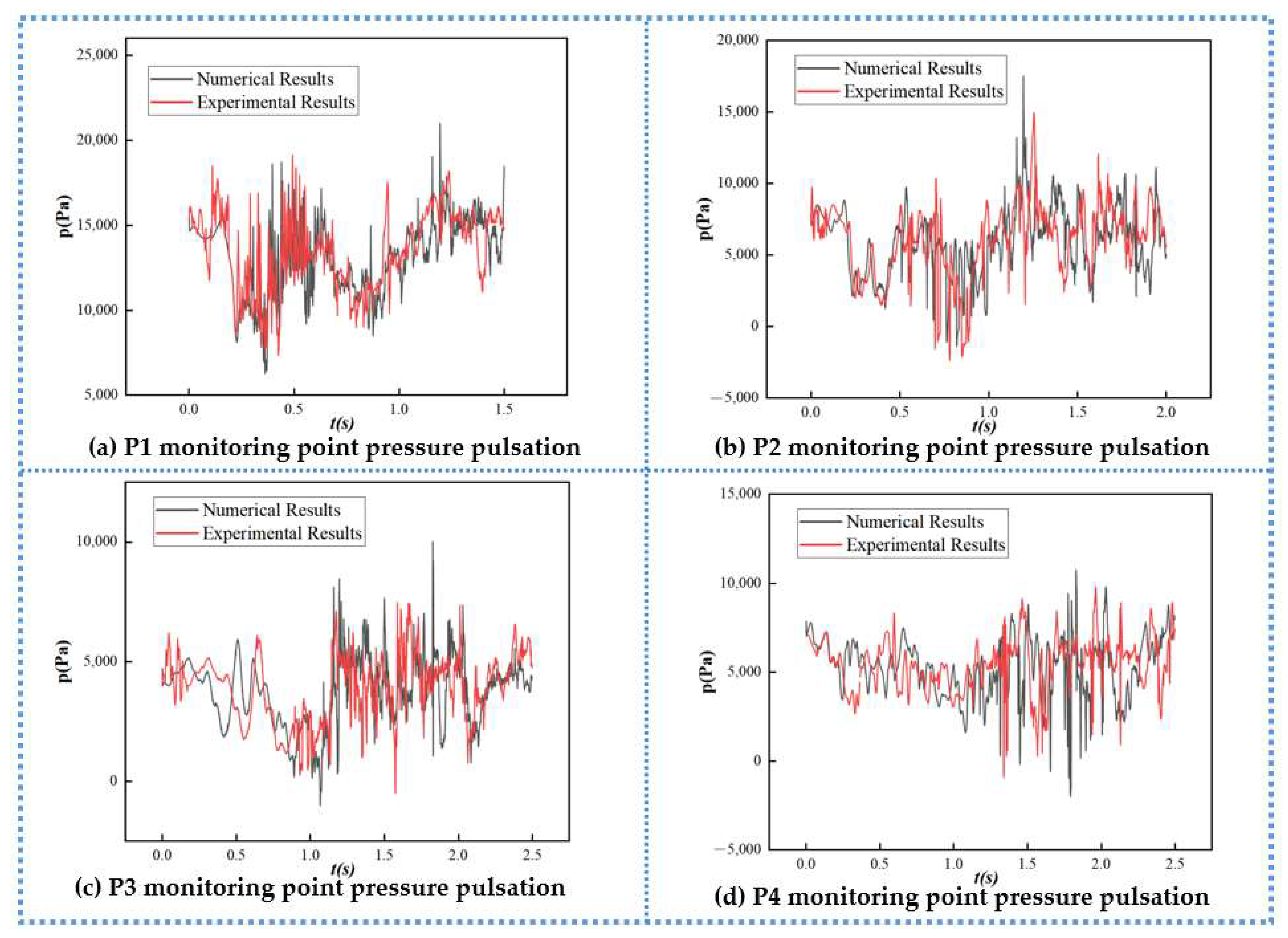
In order to further ensure the effectiveness of the CFD numerical simulation, the pressure of each monitoring point obtained via the numerical simulation of Case 12 is quantitatively compared with the experimental data. As shown in Figure 13, the simulation results are all within the error range, and the accuracy of the CFD numerical simulation is further confirmed by combining qualitative analysis with quantitative analysis.

4.2. Flow Field Analysis

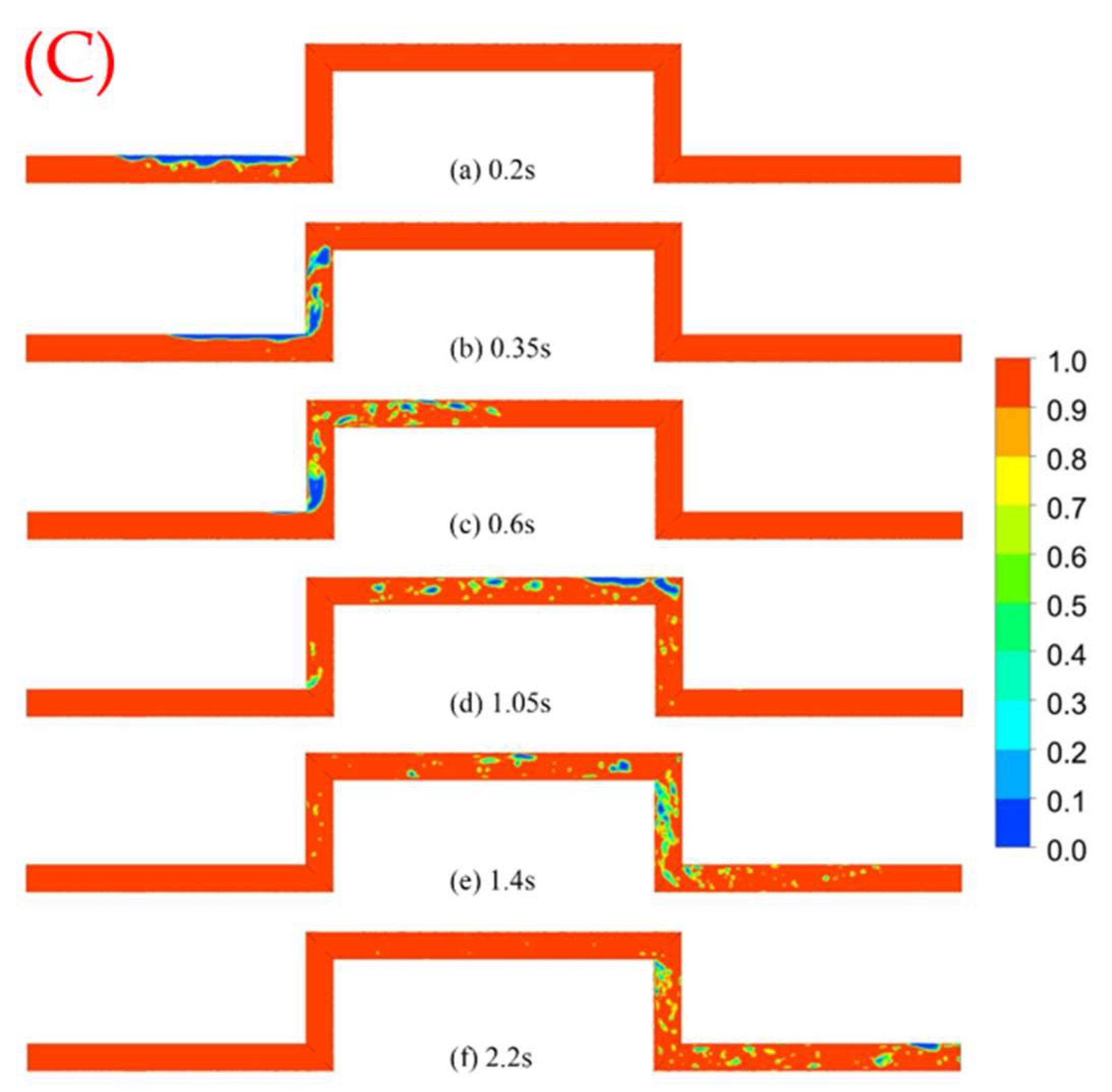
As shown in Figure 14, Figure 15 and Figure 16, in order to observe the change in flow patterns in the pipe, the center cross-section of the pipe section is selected to observe the cloud map of the water- and gas-phase distribution, where red is defined as water and blue is defined as air.
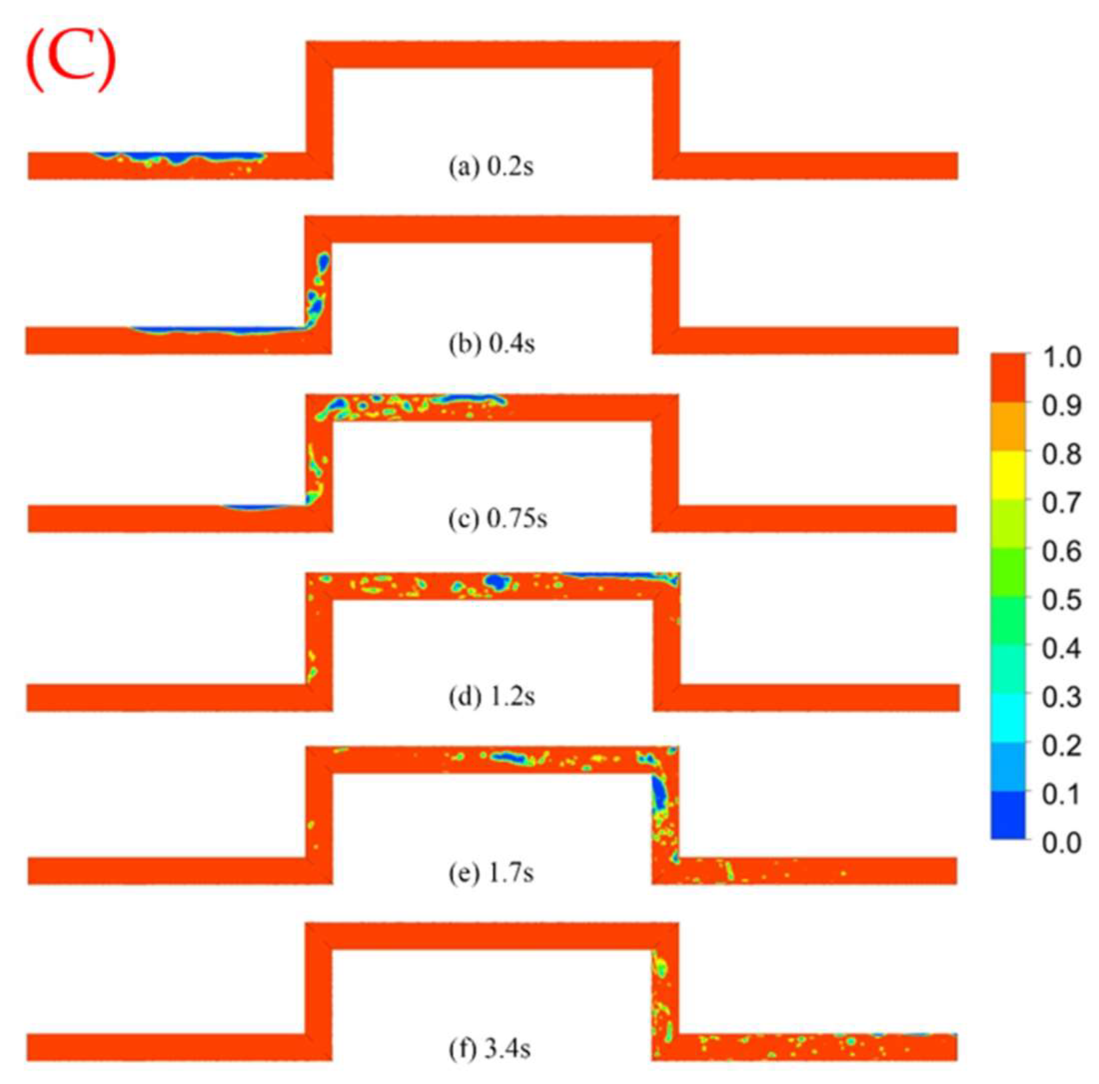
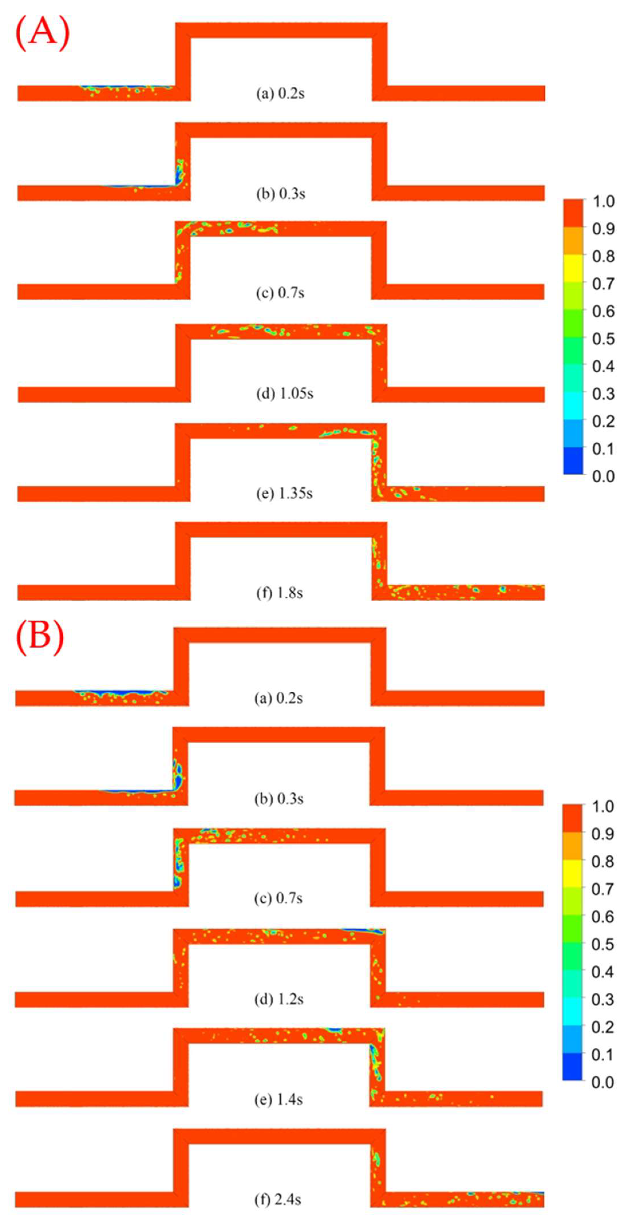
Figure 14A shows the flow process of Case 2, where, under the influence of buoyancy, the small bubbles of bubble flow gradually merge into air sacs at the top of the tube and the whole horizontal section L1 water and gas two-phase stratification is obvious, presenting a wave-like flow; the air sacs arrive at the vertical section L2, splitting into a number of large air masses, and L2 is presented as a bullet-like flow; after L2 and L3, the vertical corner, the large air mass is further split into small bubbles, and the balloon flow is gradually transformed into churning flow; the small bubbles in L3 gather into air pockets again, forming an obvious plug flow; as the test pipe section is a vertical bend, the air pockets forming in the latter half of the vertical corner of L3 struggle to be quickly washed away, and the stagnant air pockets are slowly washed into a smaller air mass, which rotates and accumulates at the left wall of the vertically descending section of L4 to form a slug flow; and when passing through the vertical bend, it further divides and flows out of the test tube section in a bubble flow type. When the flow rate of each operating mode is certain, the gas-phase motion law is basically consistent with Case 2. Figure 14B shows the flow process of Case 3—due to the increase in air content, the volume of the air pocket formed through the accumulation in the horizontal section is larger, the gas output continuity is better and the stagnation phenomenon is more likely to occur in the vertical corner. The flow pattern of the whole flow process changes into bubble flow–slug flow–churning flow–plug flow–slug flow–bubble flow–plug flow. Figure 14C shows the flow process of Case 4—with a further increase in air content, the whole process changes into bubble flow–wavy flow–slug flow–plug flow–churning flow–bubble flow.
Figure 15A shows the flow process of Case 6—with the acceleration of the water velocity, bubbles quickly gather in the horizontal section of the L1 top of the pipe, leading to the formation of plug flow; due to the operating mode with less air content, the water velocity is faster, meaning that the output of the gas continuity is poorer, and the L1 top of the pipe in the gas capsule demonstrates faster speed, leading to the formation of slug flow and churning flow of the transition flow type L2; in the L rising process of water and gas mixed with each other, significant churning flow forms; around the vertical corner, churning flow breaks into small bubbles in L3, and small bubbles, by means of buoyancy, accumulate at the top of the tube, leading to the emergence of a local plug flow; in L4, after the vertical corner, the stagnation of the airbag in the water impacts differentiation in the form of bubbles that escape from the bag in the middle part of L4 to form the slug flow; and broken bubbles make it to the top of the L5 tube, bubbling out of the test flow. Figure 15B shows the flow process of Case 7—due to the increase in the air content, the whole flow process changes into bubble flow–plug flow–slug flow–bubble flow–slug flow–bubble flow–plug flow. Figure 15C shows the flow process of Case 8—with the further increase in air content, the whole process changes into bubble flow–wavy flow–slug flow–plug flow–churning flow–slug flow–bubble flow–plug flow.
Figure 16A shows the flow process of Case 10. In the initial state, the randomly distributed bubbles rise due to buoyancy with the increase in the distance to the gas bag, and bubbles accumulate at the top of the pipe to form plug flow; due to the flow rate being larger, the gas along L2 moves, leading to the emergence of a slug flow pattern, and the slug flow in the L2 rising process begins to break, splitting to form churning flow; small bubbles at the front of the L3 rapid flow, leading to the emergence of bubble flow and churning flow transition; bubbles from L3 flow through the vertical corner into L4, and due to the water flow velocity being higher and the air content being low, only some of the bubbles accumulate to form a local churning flow; in L5, after some of the bubbles in the top of the tube accumulate in the airbag, a local plug flow occurs out of the test tube section. Figure 16B shows the flow process of Case 11—with the increase in bubble density, the whole flow process changes into bubble flow–slug flow–plug flow–slug flow–churning flow–bubble flow–plug flow. Figure 16C shows the flow process of Case 12—with the further increase in the air content, the whole flow process changes into bubble flow–wavy flow–slug flow–churning flow–bubble flow–plug flow.

4.3. Pressure Pulsation Analysis

Figure 17 shows the time-domain variation in pressure pulsation in the 1.0 m/s operating mode, and it can be observed that when the air content is low, the pressure curves at each monitoring point are generally smooth, which indicates that the crushing and fusion of bubbles in the pipeline enhance the turbulence of the disturbing effect, and the greater the number of bubbles, the more intense the process and the greater the fluctuation in the pressure amplitude. Comparing the pressure fluctuations at different moments, it can be seen that there exists a stage of extremely frequent changes in pressure pulsation at each monitoring point—for example, 0.5–2.0 s at point P1 and 1.5–3.5 s at point P2—and these characteristic stages are exactly the time ranges of the flow of bubbles or air sacs in the pipeline through the region, which indicates that in the process of collapsing, aggregating, separating and mingling with the aqueous phase of the bubbles, the gas–liquid phases exhibit disorder and uncertainty, causing the pressure pulsation to increase and decrease steeply.
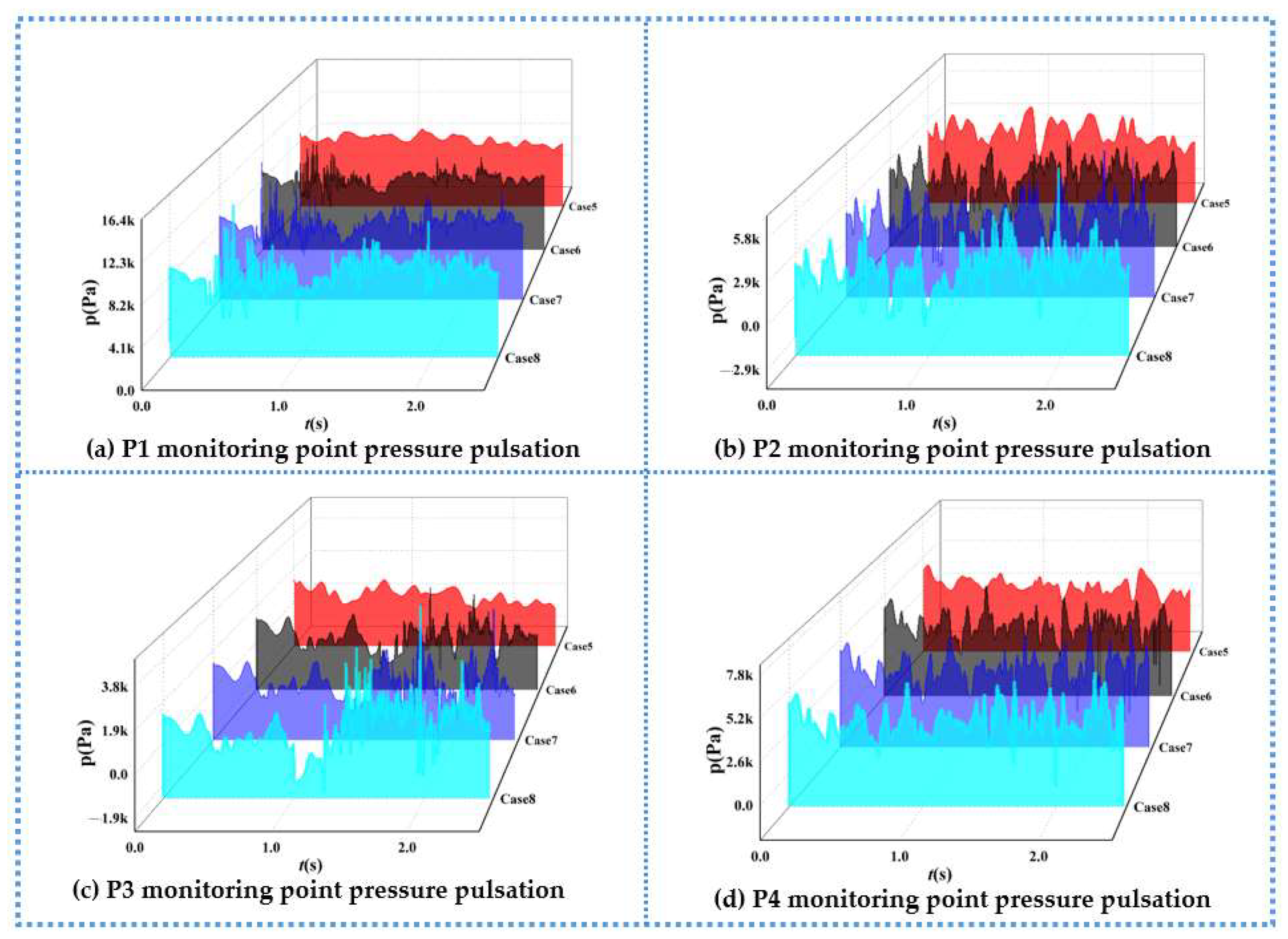
Figure 18 shows the pressure pulsation time-domain changes at each monitoring point under the 1.5 m/s operating mode. Compared with the 1.0 m/s operating mode, with the increase in the inlet flow rate, the pressure amplitude generally increases, and the characteristic phase of high-frequency pressure changes is advanced, but the pressure waveforms inside the pipeline still have a high similarity. The frequency of pressure pulsation changes is more frequent in the 1.5 m/s operating mode, and the phase of high-frequency and high-amplitude pressure changes caused by bubbles passing through a certain monitoring point is earlier than that of the other monitoring points, but the characteristic phase is shortened obviously, which indicates that although bubbles are retained in certain areas for a shorter period of time, the processes of bubbles collapsing, aggregating, separating and so on are more violent, and the flow structure in the pipe is more turbulent.
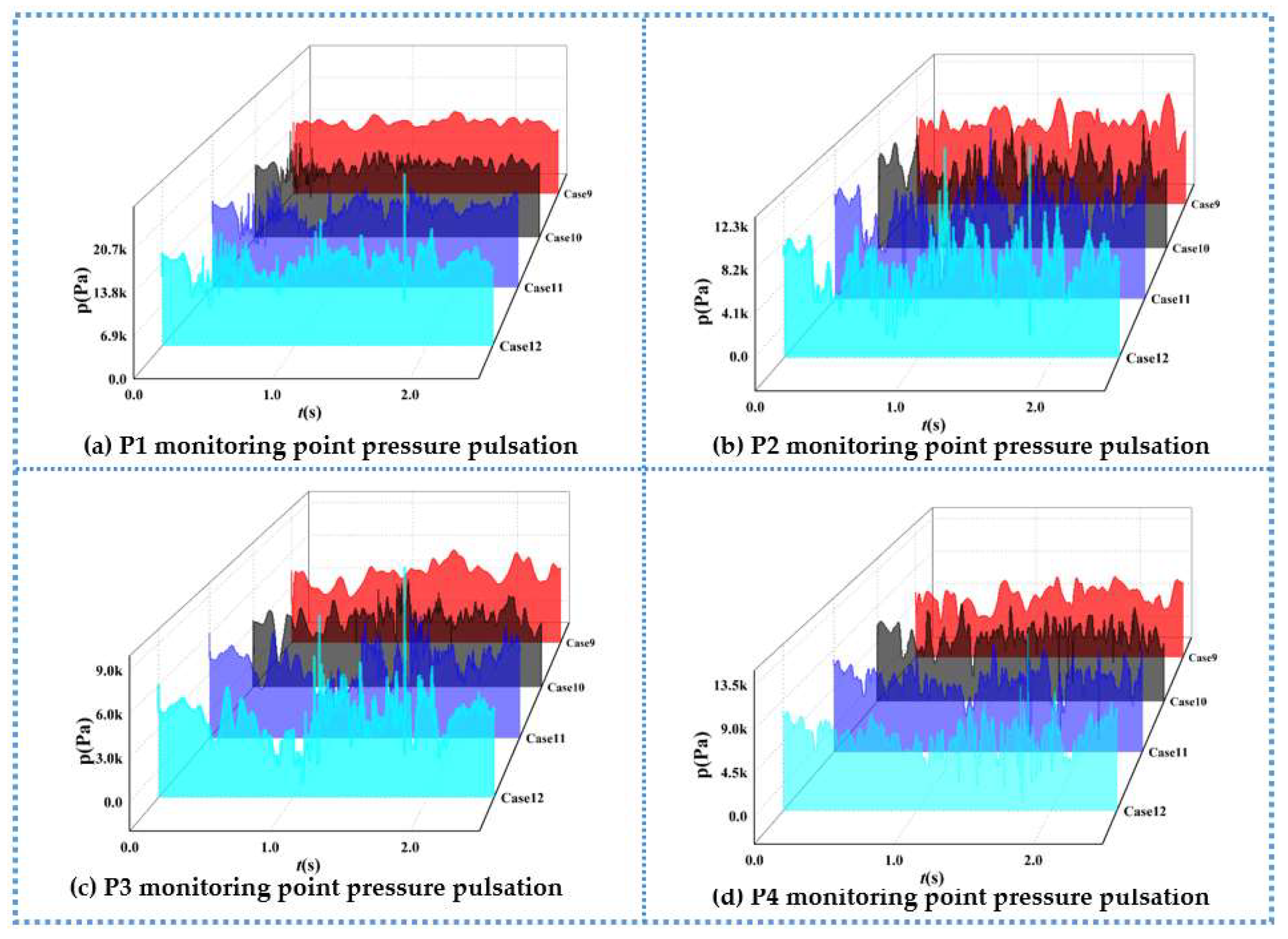
Figure 19 shows the time-domain variation in pressure pulsation at each monitoring point under the 2.0 m/s operating mode. With the further increase in the flow rate, the pressure inside the pipe also increases further, and the negative pressure condition at the monitoring points P2 and P3 is obviously improved. As for other flow rates, the higher the air content and the higher the pressure change frequency, the more obvious the turbulence effect caused by bubble breakup and fusion. Unlike other flow rates, under the impact of faster water flow, the time that bubbles remain in a certain region is shorter, so the flow pattern changes caused by bubble collapse and aggregation are more rapid, the flow pattern is more turbulent, and the fluctuation in pressure pulsation amplitude is more obvious.
In order to further analyze the variation in the main characteristics of pressure pulsation, a dimensionless number, H , is introduced to characterize the pressure pulsation properties [37].
H = H H = P i m a x P i m i n ρ g H
where H is the relative pressure pulsation amplitude; ΔH is the peak pressure pulsation, m; H is the hydraulic head, m; and P i m a x and P i m i n are the corresponding maximum and minimum values of pressure at point i, Pa.
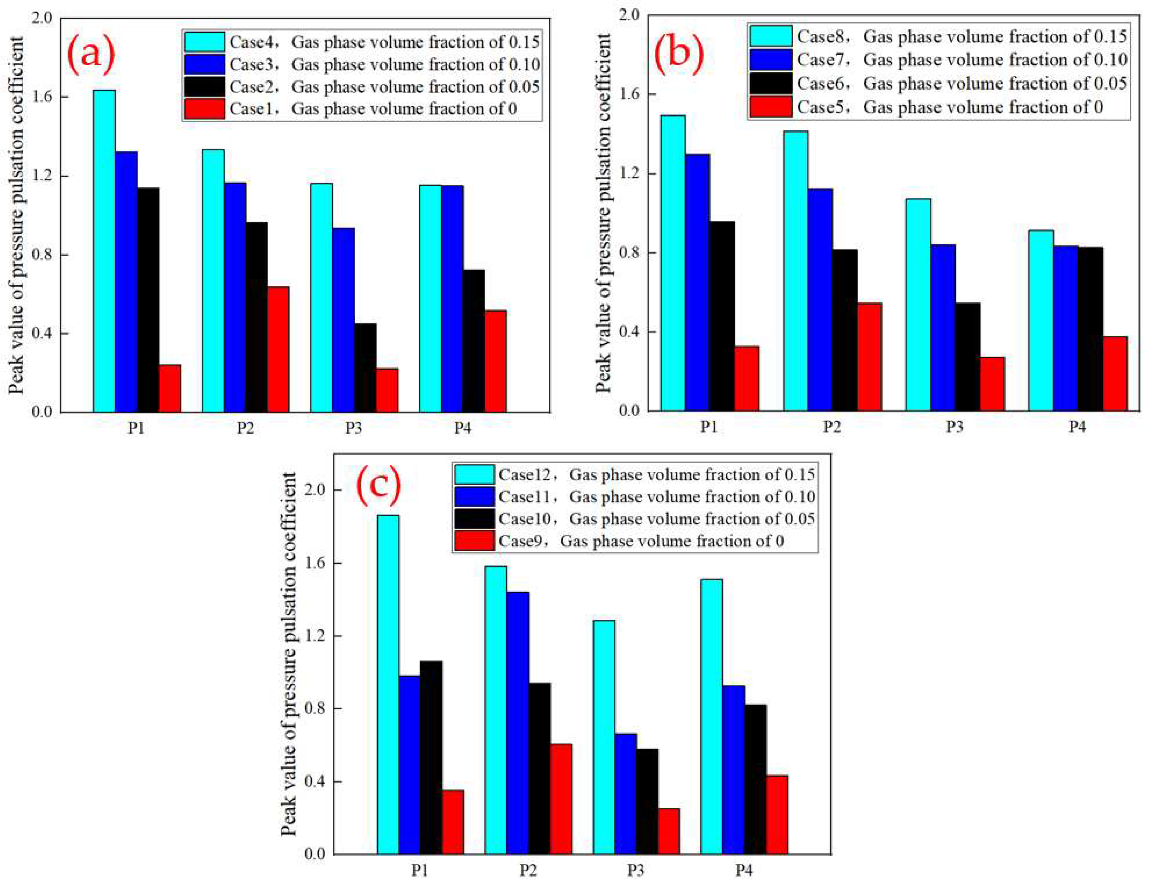
Figure 20 shows the variation in the relative pressure pulsation amplitude at each monitoring point, and it can be observed that the relative pressure pulsation amplitude decreases with the decrease in air content. Under the condition of the 0.15-air content operating mode, the highest relative pressure amplitude is observed, which is generally two to six times that of the 0-air content operating mode and which indicates that the bubbles greatly enhance the turbulence perturbation in the process of movement. The higher the number of bubbles, the stronger the pressure pulsation caused. At the same time, the velocity of water flow has less influence on the relative pressure pulsation amplitude, which indicates that the air content is the main factor affecting the relative pressure pulsation amplitude compared with the velocity of water flow. For the monitoring points at different locations, the relative pressure pulsation amplitude is significantly higher than that at the other monitoring points because the air pockets generated by the convergence of air bubbles at the P1 monitoring point have a longer retention time and the flow pattern changes drastically.

5. Conclusions

Based on the physical model test and the CLSVOF gas–liquid two-phase pipe flow numerical simulation, different flow rates and different air contents within the hump pipe flow transient process were studied in this paper, and the hump pipe pressure pulsation propagation law was compared and analyzed. The research results can provide a theoretical basis and calculation parameters for stagnant gas burst prediction and water hammer protection in aqueduct systems. The main conclusions are as follows.
(1)
The random distribution of bubbles in the test tube section was analyzed, the random distribution of bubbles law was measured, the final bubble size was obtained as a lognormal distribution law, and the equivalent diameter was between 3 mm and 10 mm. The higher the air content, the more obvious the phenomenon of small bubbles aggregating to form large bubbles. However, the distribution position of bubbles is random, and the relationship between bubble size and bubble distribution position is also random.
(2)
The flow pattern in the hump pipe is rich and varied, and there are five main types of flow patterns. After the 90-degree bend, the flow pattern is rapidly transformed, experiencing a complex flow pattern transformation, such as bubble flow–wavy flow–slug flow–churning flow–slug flow–bubble flow. The higher the flow rate, the more intense the flow pattern evolution process, the more disordered the flow pattern and the higher the air content. In addition to the increase in the typical flow pattern, there are also many transitional flow patterns.
(3)
When pipeline bubbles or airbags flow through a region, due to gas–liquid two-phase disorder, they will cause the region pressure pulsation amplitude to steeply increase or decrease, and pressure fluctuations are extremely frequent, in which the flow rate mainly affects the pressure pulsation amplitude, and the air content has an effect on the pressure pulsation frequency and pressure pulsation amplitude. The relative pressure pulsation amplitude decreases as the air content decreases, and the air content is the main factor affecting the relative pressure pulsation amplitude compared to the flow rate.

Author Contributions

Conceptualization, Q.W. and J.H.; methodology, Q.W. and M.S.; software, Q.W. and H.S.; validation, Q.W.; formal analysis, J.H.; investigation, Q.W.; resources, Q.W.; data curation, H.S.; writing—original draft, Y.Z. and F.X.; writing—review and editing, Q.W. and D.L.; visualization, J.H.; supervision, Q.W.; project administration, J.H.; funding acquisition, J.H. All authors have read and agreed to the published version of the manuscript.

Funding

This work is supported by the Key Joint Funds of the Zhejiang Provincial Natural Science Foundation of China (LZJWZ22E090004).

Data Availability Statement

The original contributions presented in the study are included in the article, further inquiries can be directed to the corresponding author.

Acknowledgments

We are very grateful to the anonymous reviewers for their constructive comments and suggestions.

Conflicts of Interest

The authors declare no conflict of interest.

References

  1. Valve, V.M.; Corp, M. Protecting Drinking Water Pipelines with Inflow Prevention; American Society of Sanitary Engineering: Elmhurst, IL, USA, 2011. [Google Scholar]
  2. Pozos, O.; Gonzalez, C.A.; Pedrozo, A.; Sanchez, A.; Rodal, E. Boundary between air entrainment and air transport downstream of a hydraulic jump in circular conduits. In Proceedings of the 5th IAHR International Symposium on Hydraulic Structures, Brisbane, Australia, 25–27 June 2014. [Google Scholar] [CrossRef]
  3. Lu, K.M.; Zhou, L.; Cao, B.; Wang, H. Three-dimensional dynamic characteristics simulation of water flow impacting the trapped air mass in undulating pipeline. J. Irr. Dra. Mac. Eng. 2020, 38, 384–389+402. [Google Scholar]
  4. Guo, Y.X.; Yang, K.L.; Guo, X.L.; Fu, H. Influence of retained bubbles on water delivery capacity during water filling of large pipeline water delivery system. J. Hydraul. Eng. 2013, 44, 6. [Google Scholar] [CrossRef]
  5. Lu, K.M.; Zhou, L.; Liu, J. Three-dimensional numerical simulation of water impact on multi-stage stagnant air mass. J. Irr. Dra. Mac. Eng. 2021, 39, 6. [Google Scholar]
  6. Zheng, Y.; Liu, D.Y.; Zhang, J.; Suo, L.S. Summary of research on gas-liquid two-phase transient flow in pressurized water pipeline system. J. Hohai Univ. 2002, 30, 5. [Google Scholar] [CrossRef]
  7. Kranenburg, C. The Effects of free gas on cavitation in pipe tines. In 1st Inter Conference on Pressure Surges; British Hydromechanics Research Assoc: Cranfield, UK, 1972; pp. 41–52. [Google Scholar]
  8. Brown, R.J. Water column separation at to pumping pants. J. Basic. Eng. Trans. 1968, 90, 521–531. [Google Scholar] [CrossRef]
  9. Simpson, A.R.; Bergant, A. Numerical comparison of pipe-column-separation models. J. Hydraul. Eng. 1994, 120, 361–377. [Google Scholar] [CrossRef]
  10. Bergant, A.; Simpson, A.R. Pipeline column separation flow regimes. J. Hydraul. Eng. 1999, 125, 835–848. [Google Scholar] [CrossRef]
  11. Yang, K.L.; Dong, X.L. Study on dynamic characteristics of bubbles in long-distance water conveyance pipeline of hydropower station. J. Hydraul. Eng. 1998, 29, 6–16. [Google Scholar] [CrossRef]
  12. Yang, K.L. Research progress and frontier scientific problems of hydraulic control for long-distance water conveyance. J. Hydraul. Eng. 2016, 47, 424–435. [Google Scholar] [CrossRef]
  13. Tokuhiro, A.; Maekawa, M.; Iizuka, K. Turbulent flow past a bubble and an ellipsoid using shadow-image and PIV techniques. Int. J. Multiph. Flow 1998, 24, 1383–1406. [Google Scholar] [CrossRef]
  14. Rezapour, S.; Riasi, A. Experimental investigation of viscoelastic turbulent fluid hammer in helical tubes, considering column-separation. Int. J. Press. Ves. Piping 2021, 194, 104489. [Google Scholar] [CrossRef]
  15. Wan, W.; Li, C.; Yu, Y. Investigation on critical equilibrium of trapped air pocket in water supply pipeline system. J. Zhejiang Univ. 2017, 18, 167–178. [Google Scholar] [CrossRef]
  16. Jansson, M.; Andersson, M.; Karlsson, M. High-Speed Imaging of Water Hammer Cavitation in Oil–Hydraulic Pipe Flow. Fluids 2022, 7, 102. [Google Scholar] [CrossRef]
  17. Urbanowicz, K.; Bergant, A.; Kodura, A.; Kubrak, M.; Malesińska, A.; Bury, P.; Stosiak, M. Modeling Transient Pipe Flow in Plastic Pipes with Modified Discrete Bubble Cavitation Model. Energies 2021, 14, 6756. [Google Scholar] [CrossRef]
  18. He, J.; Liu, X.; Li, B.; Zhai, J.; Song, J. Cavitation Erosion Characteristics for Different Metal Surface and Influencing Factors in Water Flowing System. Appl. Sci. 2022, 12, 5840. [Google Scholar] [CrossRef]
  19. Veisi, A.; Shahsavari, M.H.; Roshani, G.H.; Eftekhari-Zadeh, E.; Nazemi, E. Experimental Study of Void Fraction Measurement Using a Capacitance-Based Sensor and ANN in Two-Phase Annular Regimes for Different Fluids. Axioms 2023, 12, 66. [Google Scholar] [CrossRef]
  20. Khan, U.; Pao, W.; Sallih, N. Numerical Gas–Liquid Two-Phase Flow Regime Identification in a Horizontal Pipe Using Dynamic Pressure Data. Appl. Sci. 2023, 13, 1225. [Google Scholar] [CrossRef]
  21. Zhao, L.; Song, Z.C.; Wu, R.C.; Wang, J.P. Theoretical Analysis of Gas Release during Transient Process of Hydraulic Transients. DEStech Trans. Soc. Sci. Educ. Hum. Sci. 2017. [Google Scholar] [CrossRef]
  22. Li, X.Q.; Meng, L.P.; Li, P.; Cai, Z.H.; Liu, J.W.; Wang, F.J. Influence of trapped gas on operation stability of diversion system of hydropower station. J. Hydroelectr. Eng. 2017, 43, 4. [Google Scholar]
  23. Zhou, L.; Liu, J.; Huang, K.; Liu, D.Y. Numerical simulation of transient flow with trapped air mass during start-up and filling of water pipeline Influence of trapped gas on operation stability of diversion system of hydropower station. Adv. Sci. Tech. Water Resour. 2021, 41, 1–7. [Google Scholar]
  24. Apollonio, C.; Balacco, G.; Fontana, N.; Giugni, M.; Marini, G.; Piccinni, A.F. Hydraulic Transients Caused by Air Expulsion during Rapid Filling of Undulating Pipelines. Water 2016, 8, 25. [Google Scholar] [CrossRef]
  25. Vasconcelos, J.G.; Wright, S.J. Rapid Flow Startup in Filled Horizontal Pipelines. J. Hydra. Eng. 2008, 134, 984–992. [Google Scholar] [CrossRef]
  26. Ramos, H.M.; Fuertes-Miquel, V.S.; Tasca, E.; Coronado-Hernández, O.E.; Besharat, M.; Zhou, L.; Karney, B. Concerning Dynamic Effects in Pipe Systems with Two-Phase Flows: Pressure Surges, Cavitation, and Ventilation. Water 2022, 14, 2376. [Google Scholar] [CrossRef]
  27. Feng, L.; Yao, Q.Y. Numerical simulation of gas-liquid two-phase flow in pressure pipeline of pumping station based on VOF model. China Rural. Water Hydropower 2012, 12, 124–126+130. [Google Scholar]
  28. Wang, Z.W.; He, Y.P.; Li, M.Z.; Qiu, M.; Huang, C.; Liu, Y.D. Numerical simulation and flow pattern evolution of gas-liquid two-phase flow in 90 elbow based on computational fluid dynamics. J. Shanghai Jiaotong Univ. 2022, 56, 1159–1167. [Google Scholar] [CrossRef]
  29. Yu, Q.Q.; Shi, H.H.; Dong, R.L.; Peng, S.S. Numerical simulation of flow pattern characteristics of gas-liquid two-phase flow in vertical upward circular tube. J. Zhejiang Sci.-Tech. Univ. 2022, 47, 397–404. [Google Scholar]
  30. Bourlioux, A. A coupled level-set volume-of-fluid algorithm for tracking material interfaces. In Proceedings of the 6th International Symposium on Computational Fluid Dynamics, Lake Tahoe, CA, USA, 4–8 September 1995; p. 15. [Google Scholar]
  31. Yang, C.Z. Study on Critical Velocity of Bubble Initiation in Long Water Pipeline Pressurized by Pump. Master’s Dissertation, North China Univ. Water Res. & Electric Power, Zhengzhou, China, 2021. [Google Scholar]
  32. Shang, Z.; Lou, J.; Li, H. Simulations of flow transitions in a vertical pipe using coupled level set and VOF method. Int. J. Comp. Meth. 2017, 14, 135–141. [Google Scholar] [CrossRef]
  33. Tang, X.; Duan, X.; Gao, H.; Li, X.; Shi, X. CFD Investigations of Transient Cavitation Flows in Pipeline Based on Weakly-Compressible Model. Water 2020, 12, 448. [Google Scholar] [CrossRef]
  34. Hu, J.; Wang, Q.; Zhang, Y. Numerical and Experimental Study on the Process of Filling Water in Pressurized Water Pipeline. Water 2023, 15, 2508. [Google Scholar] [CrossRef]
  35. Ling, P.; Ting, Z.; Jian, L. Three-Dimensional Numerical Study of Dam-Break Flood Impacting Problem with VOF Method and Different Turbulence Closures. Water Res. Manag. 2023, 37, 1–21. [Google Scholar] [CrossRef]
  36. Devade, K.D.; Pise, A.T.; Urade, A.R. Numerical Analysis of Flow Behavior in Vortex Tube for Different Gases. Mech. Eng. Res. 2017, 7, 18–39. [Google Scholar] [CrossRef]
  37. Xu, L.C.; Peng, Y.J.; Tang, W.; Liu, D.M.; Liu, X.B. Flow Characteristics and Pressure Pulsation in the S Characteristic Area of Model Pump Turbine. Chin. J. Hydro. 2022, 37, 213–225. [Google Scholar] [CrossRef]
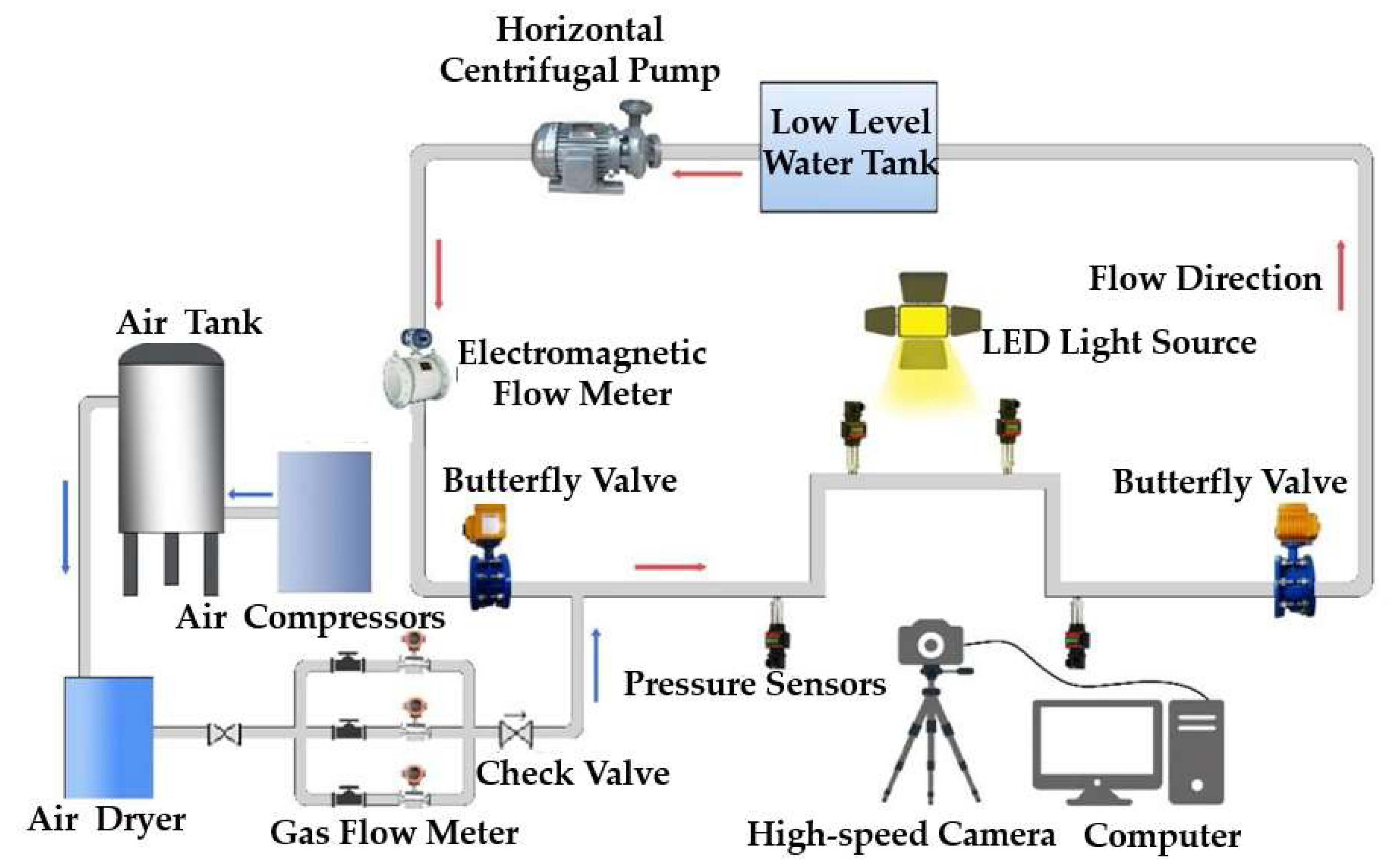
Figure 1. Water–air flow pattern categories from [22,23].
Water 15 03831 g001
Figure 2. Layout of the water–air transient flow test system.
Water 15 03831 g002
Figure 3. Physical pictures of the water supply module device: (a) QZHW200-250IA centrifugal pump; (b) motorized butterfly valve; (c) motorized regulating valve; (d) low-level water tank.
Water 15 03831 g003
Figure 4. Physical picture of the gas supply module unit: (a) gas storage tank; (b) air compressor; (c) vortex gas flow meter.
Water 15 03831 g004
Figure 5. Physical picture of the air supply module device: (a) pressure sensor; (b) DN100 hump pipe; (c) electromagnetic flow meter; (d) high-speed camera.
Water 15 03831 g005
Figure 6. Distribution of bubbles with different air contents: (a) 0.05 air content; (b) 0.1 air content; (c) 0.15 air content.
Water 15 03831 g006
Figure 7. Statistics of random distribution of bubbles.
Water 15 03831 g007
Figure 8. Three-dimensional fluid domain model of a hump pipe.
Water 15 03831 g008
Figure 9. Mesh delineation results: (a) longitudinal section mesh delineation; (b) transverse section mesh delineation.
Water 15 03831 g009
Figure 10. Grid-independent verification.
Water 15 03831 g010
Figure 11. Random distribution of bubbles in the 0–0.5 m region.
Water 15 03831 g011
Figure 12. Comparison of experimental and numerical simulation flow patterns.
Water 15 03831 g012
Figure 13. Comparison of experimental and numerical simulation pressure.
Water 15 03831 g013
Figure 14. Water–air flow pattern of the pipe with flow rate 1.0 m/s: (A) Case 2, 0.05 air content; (B) Case 3, 0.10 air content; (C) Case 4, 0.15 air content.
Water 15 03831 g014aWater 15 03831 g014b
Figure 15. Water–air flow pattern of the pipe with flow rate 1.5 m/s: (A) Case 6, 0.05 air content; (B) Case 7, 0.10 air content; (C) Case 8, 0.15 air content.
Water 15 03831 g015aWater 15 03831 g015b
Figure 16. Water–air flow pattern of the pipe with flow rate 2.0 m/s: (A) Case 10, 0.05 air content; (B) Case 11, 0.10 air content; (C) Case 12, 0.15 air content.
Water 15 03831 g016aWater 15 03831 g016b
Figure 17. Time-domain plot of pressure pulsation at each monitoring point (1.0 m/s).
Water 15 03831 g017
Figure 18. Time-domain plot of pressure pulsation at each monitoring point (1.5 m/s).
Water 15 03831 g018
Figure 19. Time-domain plot of pressure pulsation at each monitoring point (2.0 m/s).
Water 15 03831 g019
Figure 20. The relative pressure pulsation amplitude: (a) 1.0 m/s; (b) 1.5 m/s; (c) 2.0 m/s.
Water 15 03831 g020
Table 1. Characteristic parameters of the horizontal centrifugal pump.
Model NumberDesign Flow Rate
(m3/h)
Design Head
(m)
Rated Speed
(r/min)
Motor Power
(kW)
Cavitation Allowance
(m)
QZHW200-250IA
Pipeline centrifugal pump
358141450224
Table 2. Calculation operating mode table.
Operating ModeInlet Flow Rate (m/s)Gas-Phase
Volume Fraction
Outlet Absolute Pressure (Pa)
Case 11.00101,325
Case 21.00.05101,325
Case 31.00.10101,325
Case 41.00.15101,325
Case 51.50101,325
Case 61.50.05101,325
Case 71.50.10101,325
Case 81.50.15101,325
Case 92.00101,325
Case 102.00.05101,325
Case 112.00.10101,325
Case 122.00.15101,325
Table 3. Parameters of physical properties of water and gas phases.
MediumDensity (kg/m3)Dynamic
Viscosity
(Pa∙s)
Surface
Tension
(N/m)
Temp
(°C)
Atmospheric
Pressure
(Pa)
Water998.21.003 × 10−30.07220101,325
Air1.2251.7894 × 10−5
Disclaimer/Publisher’s Note: The statements, opinions and data contained in all publications are solely those of the individual author(s) and contributor(s) and not of MDPI and/or the editor(s). MDPI and/or the editor(s) disclaim responsibility for any injury to people or property resulting from any ideas, methods, instructions or products referred to in the content.