Article

Treatment of Dyeing Wastewater Using Foam Separation: Optimization Studies

1
Department of Chemical Engineering, Jaypee University of Engineering & Technology, A.B. Road, Guna 473226, India
2
Energy Cluster, Department of Chemical Engineering, University of Petroleum and Energy Studies, Dehradun 248007, India
3
Interdisciplinary Research Center for Membranes and Water Security, King Fahd University of Petroleum and Minerals, Dhahran 31261, Saudi Arabia
*
Authors to whom correspondence should be addressed.
Water 2023, 15(12), 2236; https://doi.org/10.3390/w15122236
Submission received: 3 April 2023 / Revised: 24 May 2023 / Accepted: 25 May 2023 / Published: 14 June 2023

Abstract

:
Technological advancement, on the one hand, leads to the enhanced quality of the final product but on the other hand, generates a good quantity of effluent. The wastewater containing dyes which emanates from the textile industry is a cause of worry. Hence, this paper focuses on the treatment of dyeing wastewater using the foam separation process as it offers several advantages over other traditional methods. Methylene blue (MB), owing to its ill effects on the entire ecosystem, has been considered as a model dye in this research work. The objective of this work is to remove MB from wastewater and at the same time, its recovery in the foam phase. The ability of sodium dodecyl sulfate (SDS) and sodium dodecyl benzene sulfonate (SDBS) to perform separation of MB was compared. The following operating parameters were identified: contact time, initial pH of a feed solution, surfactant dose, volumetric flow rate of air, volume of liquid in the column, and concentration of dye; which greatly influence the separation parameters (% removal and enrichment ratio). Keeping in mind the importance of recovering MB from dilute solutions, the method to enhance foam drainage was devised by inserting an inverted funnel in the foam phase. In the presence of inverted funnel, the concentration of MB in the foamate doubled in comparison to the conventional column (without an inverted funnel). The comparison between SDS and SDBS divulged SDBS as a better surfactant to get concentrated solution of MB in the foamate, but the quantity of SDBS required was more. The optimization of operating variables was also done by using the Taguchi method and Grey relational analysis. Finally, the concentration of MB was discovered to be the most responsive operating parameter for both separation parameters.

1. Introduction

The discharge of numerous pollutants in water bodies with distinct physical and chemical characteristics endangers the lives of human beings and aquatic species due to their hazardous nature. The water contaminated with dye is viewed as a menace to the environment that encourages environmentalists to search for sustainable solutions. The following industries are reported to have contributed significantly to the formation of colored wastewater: (i) textile, (ii) dyestuffs, (iii) paper, and (iv) plastics. The worldwide annual production of dyes, as mentioned in the literature is mammoth 7,00,000 metric tons with huge 100,000 varieties of commercial dyes known to date [1,2,3]. The organic nature of dyes along with the complicated aromatic structure is mainly responsible (i) for their non-biodegradable nature, and (ii) for imparting color [4,5,6,7]. The receiving water bodies experience a noticeable increase in turbidity levels along with an obstruction in the sunlight penetration owing to which the process of photosynthesis of plants and aquatic life gets affected [8,9]. Further the condition gets aggravated when chemicals present in the dye evaporate which may lead to the condition of gasping upon inhalation. Its deleterious effects on health include skin-related diseases and visual impairment on coming in contact with the skin and eyes [10]. Dyes are also reported to cause cancer with severe long-term effects [11]. Hence, development of appropriate dye effluent treatment methods which are both cost- effective and environmentally friendly before its discharge is the need of the hour.
The dye removal techniques which are generally being employed are classified as physical, chemical, and biological [12]. The following methods fall under physical processes for the isolation of dye: (i) adsorption, (ii) ultra-filtration, (iii) ion exchange (iv) coagulation, etc. [13]. The techniques such as oxidation, Fenton reaction, Ultraviolet irradiation, etc. belong to chemical processes [14]. The biological processes use a combination of aerobic and anaerobic techniques for treating dyeing wastewater [15]. The two most important features i.e., simplicity and effectiveness of physical processes make it the most preferred technique for dye separation in comparison to chemical and biological processes [16]. Adsorption is reported to be a widely recognized technique. Many a time, the cost of the adsorbent becomes the limiting factor to enable higher removal efficiencies. Foam fractionation, a physical technique, has been employed for this study for the isolation of MB from a dilute aqueous solution. It is an adsorptive bubble separation method that is considered appropriate for treating low-concentration effluents and it does not require (i) huge amounts of chemicals, and (ii) much energy; for the separation compared to other conventional separation methods [17]. This technique is being successfully implemented in the following areas: (i) isolation of proteins [18,19], (ii) removal of heavy metal ions [20], (iii) separation of surfactants [21], and (iv) removal of aromatic molecules [22]. The other attributes that make this technique appealing for the researchers are (i) its low capital and operating cost, (ii) it does not require any solvent to effect separation, (iii) depending upon the requirement it can be run in any mode (batch, semi-continuous or continuous), and (iv) it is an environmental friendly separation method [23,24]. Foam fractionation is similar to the adsorption process. In the adsorption technique, the target species gets adsorbed on the active sites that are available on the external surface as well as on the interior of the solid adsorbent particle. While in foam fractionation, the solute adsorption occurs only on the external surface of the air bubbles. These air bubbles are induced by introducing compressed air at the column’s bottom and are allowed to pass through the liquid solution to be treated [25]. Finally, foam formation takes place and it exits the column from the top which is found to be enriched with solute molecules [26]. Unlike adsorption, foam fractionation employs both the removal and recovery of solute in a single operation. This work aims at the stripping of methylene blue (MB), a cationic dye that is usually employed for dyeing fabric material. The foam fractionation technique necessitates the addition of an external agent (surfactant) for accomplishing the separation [27]. The presence of a surfactant helps in creating stable foam and it promotes the dye-surfactant aggregate formation necessary for the isolation of dye from the effluent [28]. However, limited research has so far undertaken that utilized foam separation technique for dye removal, demonstrated in Table 1. In this work, two different surfactants, namely, sodium dodecyl sulfate (SDS)and sodium dodecylbenzene sulfonate (SDBS) were used for the separation of MB and subsequently, their performances were compared. The influence of operating variables on separation parameters was evaluated by operating the foam column in a semi-continuous mode. Besides, optimization techniques were successfully implemented to find the optimum values of operating variables for achieving maximum separation. Here, separation experiments were conducted using two different columns, namely, contrasted and experimental. The significance of these columns has been discussed at appropriate locations in this paper. In this study, an attempt has been made to perform multi-objective optimization for the first time to maximize percentage removal and enrichment ratio simultaneously to determine the optimum operating conditions. Another important parameter, surface excess, found out by a few researchers only for continuous columns has been estimated in this study for semi-continuous foam fractionation column.

2. Experimental

The chemical reagents, analytical instruments employed for measurement purposes, and experimental setup along with the experimental procedure adopted to carry out the foam fractionation experiments have been discussed in this section.

2.1. Materials and Methods

The analytical grade chemicals were used in all the experiments. MB (dye), NaOH, and HCl (for maintaining pH) were procured from Merck (Mumbai, India); while the surfactants, SDS and SDBS, were purchased from LobaChemiePvt. Limited (Mumbai, India). The molecular structure of MB is shown in Figure 1. This research work made use of the following instruments for the conduct of experiments: (i) a Double beam UV-Visible spectrophotometer SL210 (Elico, Hhyderabad, India) to determine the concentration of dye in the liquid solution, (ii) a digital pH meter (Thermo Orion 420A+, Delhi, India), and (iii) magnetic stirrer (Remi, Mumbai, India).

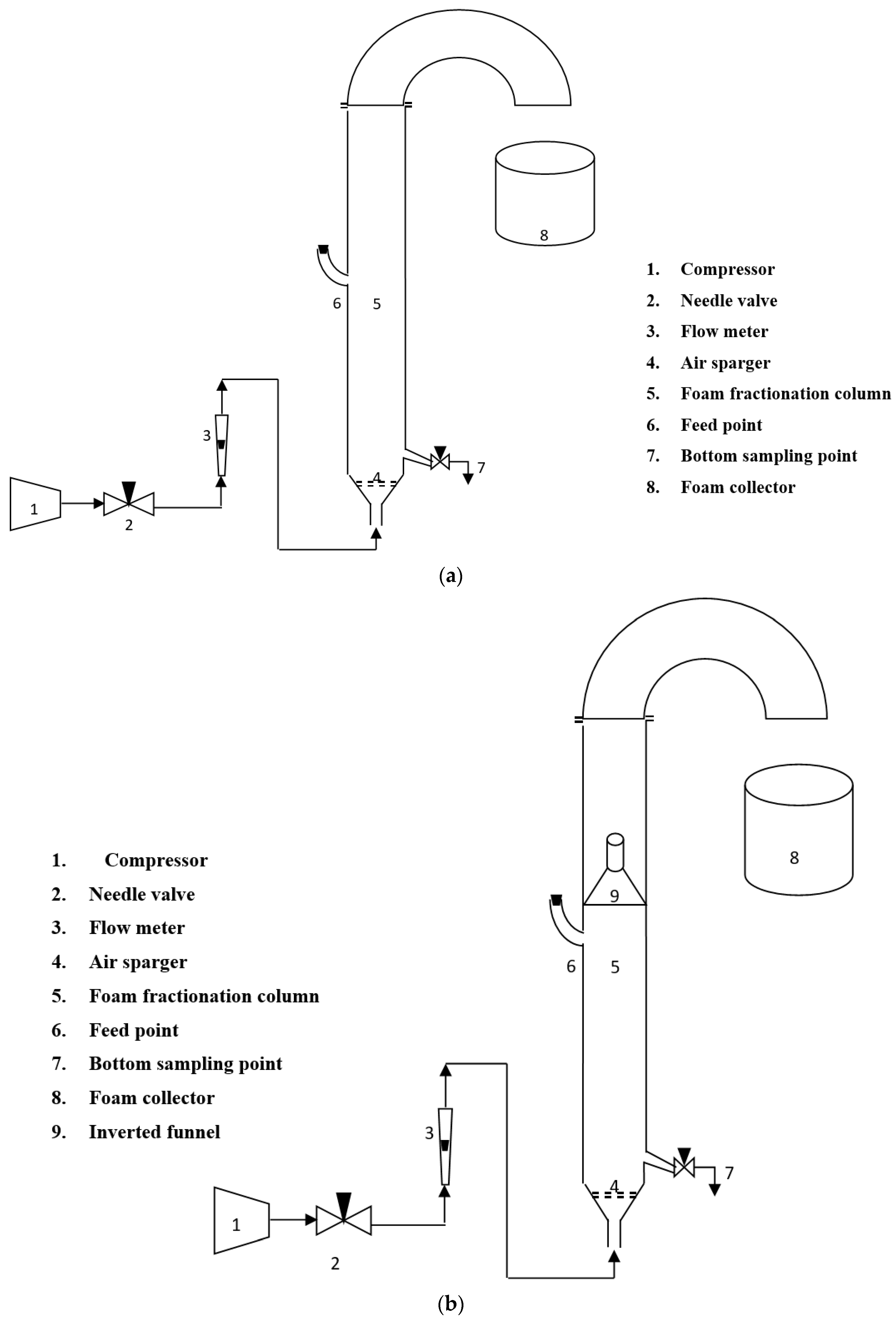
2.2. Experimental Set-Up

The diagram of the experimental set-up employed for conducting the research work is demonstrated in Figure 2a, known as the contrasted column. The following components/units were utilized to assemble the experimental set-up: (i) cylindrical glass column (L = 1100 mm, I.D = 50 mm) where feed solution was brought into contact with the air bubbles, (ii) air compressor, (iii) rotameter, for allowing the measured volume of air per unit time to pass through the liquid solution in the form of bubbles, (iv) foam receiver, a beaker to collect the foam, and (v) sintered glass filter (pore size 90–150 µm), a sparger installed at the column’s base. The dye separation experiments were also carried out by placing an inverted funnel in the cylindrical glass column to enable reduced flow area available for the foam to pass (Figure 2b), known as an experimental column.

2.3. Experimental Procedure

The experimental procedures employed were identical irrespective of the column i.e., contrasted or experimental, utilized for carrying out the removal of MB. The feed solution comprising MB, surfactant (SDS or SDBS), and water of a given concentration was prepared and then charged into a cylindrical glass column up to a specific height. The fixed volume of air per unit of time through the sparger was then introduced into the column. Air bubbles thus produced rose through the pool of liquid during which transport of MB-surfactant aggregate on air bubble occurred. Subsequently, the formation of the foam phase that took place above the liquid surface reached the column top from where it was collected in a beaker (foam receiver). It took some time for the foam to collapse, following which the concentration of MB in foamate was determined. The amount of MB left in the pool of liquid was also noted at varying times.

3. Estimation of Parameters

This section elucidates the significance and the expressions utilized for the determination of various parameters that are essential to comprehend the working of a foam fractionation column.

3.1. Separation Efficiency: % Removal and Enrichment Ratio

Percentage dye removal ( R ) was determined by using Equation (1):
R = C i C e C i × 100
where C i (mg·L−1) & C e (mg·L−1) are the MB concentrations in the solution at the start and end of the experiment. It signifies the percentage reduction in the concentration of MB with respect to C i .
The following expression was utilized for calculating the enrichment ratio ( E )
E = C f C i
where C f is the concentration of MB in the collapsed foam phase in mg·L−1. It is a measure of enhancement of MB concentration in the foam phase with respect to C i .

3.2. Foam Wetness

Foam wetness is a vital parameter in assessing the fraction of liquid in the foam phase, which comprises both liquid and gas phases. The liquid holding capacity (wetness) of foam provides a qualitative idea regarding the enrichment of the foam and it also influences the behavior of the separation column, given by Equation (3):
e x i t = V f V f + V g
where V f (mL) is the volume of collapsed foam accumulated in a beaker in a specified time, and V g (mL) is the volume of air bubbled through the pool of liquid in a given time. Here, these volumes were collected for a time duration of 1 min.

3.3. Bubble Size

The significance of bubble diameter lies in the fact that the foam fractionation process makes use of the bubbles’ surface for the separation to take place. Hence, to evaluate the interfacial surface area available for adsorption, knowledge of bubble size distribution is a must. A photographic technique was utilized and the pictures of bubbles rising through the column of liquid were captured using a digital camera (Make: Nikon Coolpix P600 (Kolkata, India); Frame size: 4608 × 3456; Frame rate = 120 frames per second). The image captured for every experimental run consists of around 100–200 bubbles. ImageJ1.5.3, an image analysis software, was then used for the determination of the distribution of bubbles and their mean diameter. Assuming the shape of bubbles to be spherical, the Sauter’s mean diameter ( d 32 ) in m, was determined by Equation (4):
d 32 = i = 1 n d i 3 i = 1 n d i 2
In the above equation, the diameter of the individual bubble is represented by d i (in m) and each photograph contains n bubbles.

3.4. Surface Excess

Surface excess, yet another essential parameter, quantifies the MB adsorption on the surface of an air bubble. This term is analogous to the adsorption capacity of an adsorbent which is given by the amount adsorbed on a unit mass of adsorbent. Surface excess, Γ (mg·m−2) was evaluated by using the following expression:
Γ = C f C e V f d 32 0.006 V g
The MB concentration in the interstitial liquid present in the foam phase is equal to C e .

4. Importance of Experimental Column

The experimental column plays a pivotal role in enhancing the enrichment ratio, a separation parameter that determines the purity of a recovered species (MB in this case) in a foam phase. There are two methods reported in the literature to achieve greater enrichment ratios: (i) increase interfacial adsorption, or (ii) increase foam drainage [35]. Interfacial adsorption is enhanced by generating a higher surface area. While greater foam drainage implies the release of a good volume of entrained liquid. Usually, it is found that if the gas-liquid interfacial area is enhanced then the foam drainage automatically gets reduced and vice versa.For example, the increase in air flow rate engenders interfacial adsorption to improve and foam drainage to decrease, while a decrease in air flow rate results in adequate foam drainage with poor interfacial adsorption. This type of behavior of operating variables on enrichment ratio prompted researchers to use either the interfacial adsorption enhancement technique or foam drainage intensification method. Two ways are generally employed to strengthen the interfacial adsorption i.e., multistage approach [36] (adsorption occurring mainly in bulk liquid phase) or the reflux approach [37] (adsorption in foam phase dominates). In both these methods, to enable better interfacial adsorption, the entrained liquid should have a higher solute concentration which can only be realized if the effective collapse of foam occurs. But, the greater degree of stability of the foam in some cases hampers the phenomena of foam collapse, considered to be a major drawback of the interfacial adsorption enhancement technique. Hence, the main focus of researchers is to find ways that facilitate the liberation of interstitial liquid present in the foam phase during its upward movement i.e., foam drainage enhancement methods. Prevalently, the hindrance offered to the liquid flowing downwards should be as low as possible contained in the up-flowing foam, which is the only method to enhance foam drainage [38]. The separation experiments carried out at elevated temperatures is one such method to increase the foam drainage as the viscosity of the down-flowing liquid undergoes a reduction in viscosity at higher temperatures. Higher operational costs and chances of product degradation make this temperature elevation technique unfeasible [39]. Foam drainage can also be improved by having a sparger of bigger pore size at the base of the column that could generate bubbles of large diameter but it would take place at the cost of a poor recovery rate. The insertion of foreign devices such as spiral internal, parallel inclined channels, and perforated plates; in the column is the most favorable and well-accepted technique to enable greater foam drainage. In view of this, an inverted funnel was inserted in the foam phase to enable greater foam drainage and hence a greater enrichment ratio known as the experimental column. The gradual reduction in the flow area available for the flow of foam due to obstruction (the inverted funnel) led to the ejection of a greater amount of entrained liquid.

5. Selection and Range of Operating Variables

Any experimental investigation commences with the identification of operating variables along with their respective ranges in which their effect on output parameters is seen. Table 2 depicts the range of operating variables chosen for this study to evaluate the column’s performance. The volume of the feed solution was altered from 600–750 mL, keeping in mind the dimensions of the column so that adequate foam generation could take place above the liquid pool to enable effective separation. The variation in airflow rate from 150–250 mL·min−1 was considered to ensure that the column could be operated for at least 30 min before the foam formation ends. The MB concentration, taking into account the literature review (Table 3), was altered from 5–25 ppm. The other operating parameters such as contact time, SDS/SDBS concentration, and the pH of the solution fed will be considered in succeeding sections.

6. Estimation of Optimized Parameters

Owing to the large number of process variables involved in the foam separation process, it is always good to fix the values of some of the operating variables and then obtain the impact of the remaining variables on the column performance. The following operating variables: (i) contact time, (ii) surfactant concentration, and (iii) initial pH of a solution; were first fixed by estimating their optimized values. These optimum values were determined by conducting the experiments at the middle values of the remaining variables mentioned in Table 2.

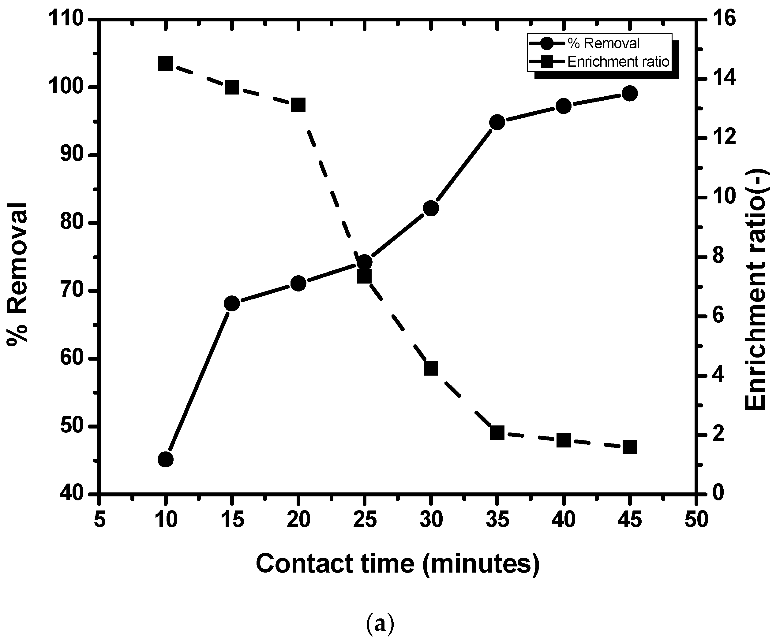
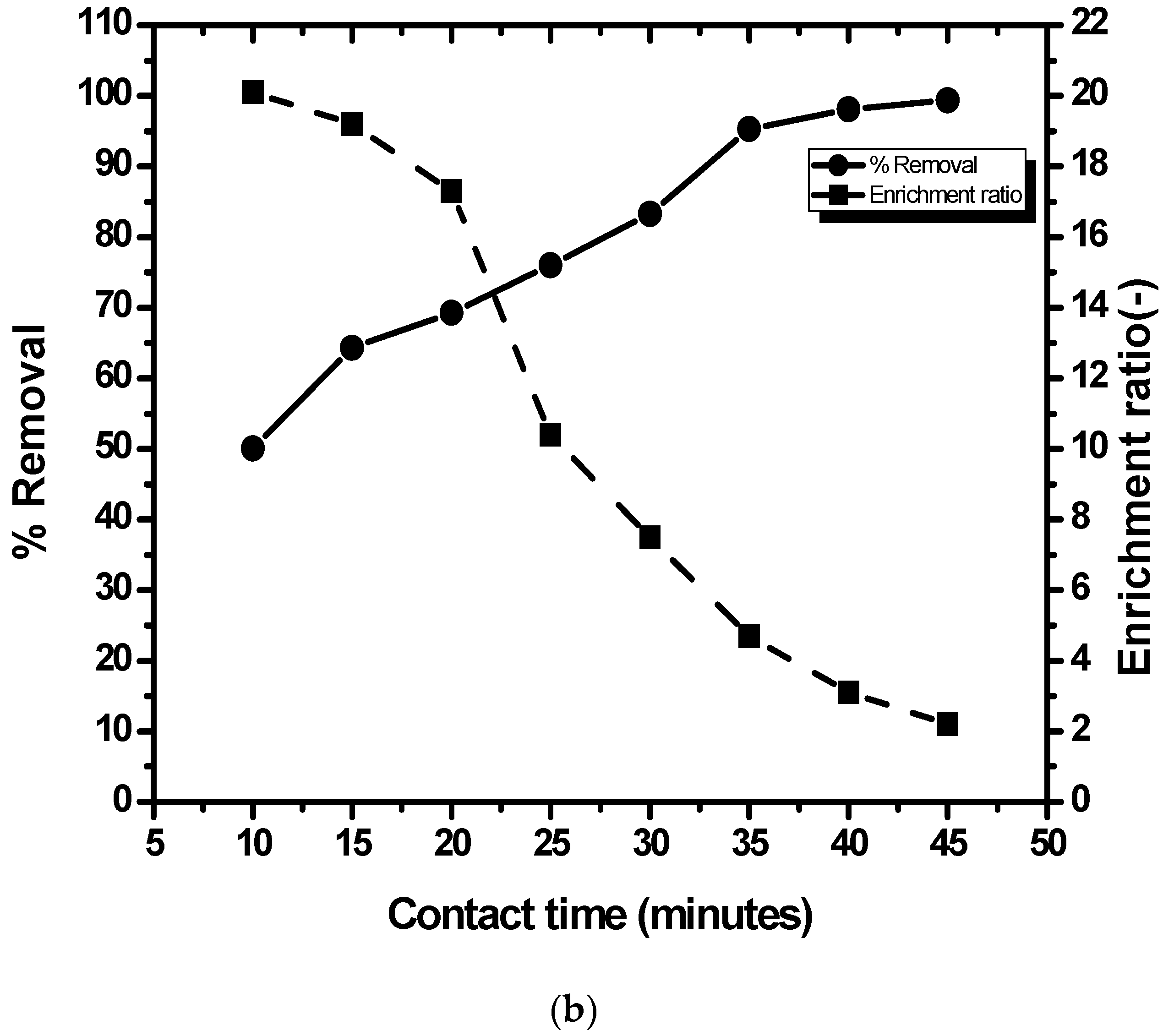
6.1. Effect of Contact Time

The unsteady state behavior of the column was chiefly responsible for the variation in separation parameters with time. The time for which the column needs to be operated has to be fixed as only then does the comparison between the performances of the column at various operating conditions has some significance. The optimized contact time was determined from Figure 3, using SDS and SDBS respectively, which demonstrate the variation in enrichment ratio and % removal with the progression of time. The rise in the percentage removal of dye, as time progresses, was attributed to the decrease in MB concentration in the pool of liquid. But at the same time, the enrichment ratio dipped due to the lesser amount of dye left in the solution with the passage of time resulting in successively decreasing MB concentrations in the foam phase. The time at which both the curves intersect (Figure 3) is known as the optimum contact time and it was found to lie between 20–25 min. The optimum contact time, in a similar fashion, obtained by operating the column at various other operating conditions (not shown here) was also found to lie in the same range. Henceforth, the influence of all the operating variables on the performance of the column was noted by conducting the experiments for the same time (25 min).

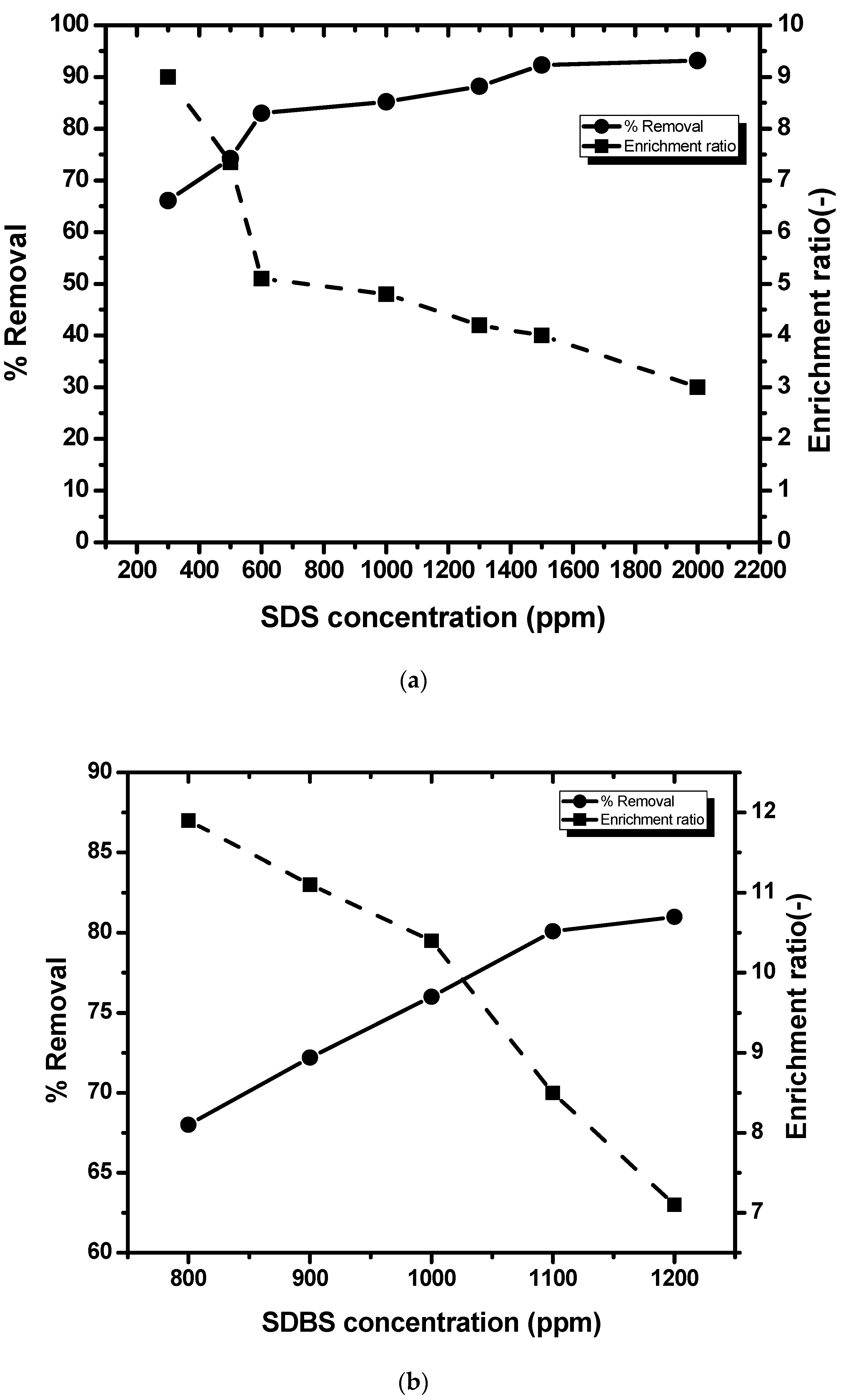
6.2. Effect of Surfactant Concentration

The recovery of a dye from the feed solution is greatly influenced by the surfactant dosage as it acts as a collector that facilitates dye removal. Hence, the determination of optimum surfactant dosage is always necessitated. The range of surfactant doses in which the performance of the foam fractionator needs to be investigated depends on its critical micelle concentration (CMC). There is a significant decline in surface tension with the rise in surfactant concentration till CMC is approached following which the surface tension doesn’t vary much. The CMC of SDS is close to 2300 ppm. Hence, the influence of SDS concentration was determined in the range of 300–2000 ppm. Figure 4a shows the variation in separation parameters with SDS concentration. The enrichment ratio plummeted with the rise in the amount of SDS owing to an increase in viscosity as a consequence of which the phenomena of releasing the entrained liquid back into the bulk liquid pool got hampered, resulting in the production of wet foam. The percentage removal was found to increase from 66% to 93% when SDS concentration was raised from 300–1500 ppm, with negligible change in percentage removal past 1500 ppm. The initial growth in percentage removal (till 1500 ppm) was because the addition of surfactant caused a greater quantity of surfactant-dye aggregate formation as a result of which enhanced adsorption on the surface of bubbles occurred. At SDS concentrations greater than 1500 ppm, the surface of the bubble got saturated with adsorbed molecules of surfactant, resulting in insignificant variation in the percentage removal of MB. The optimum concentration of SDS is 500 ppm (Figure 4a).
However, the column behaved entirely in a different manner when experiments were conducted using SDBS as a collector. The lowest SDBS concentration needed to operate the foam fractionator was 800 ppm, more than its CMC value of 698 ppm, to enable interrupted production and transport of foam for at least 30 min. Lower concentrations of SDBS (<600 ppm) could not generate enough foam and the foam did not even last for 15 min which subsequently led to extremely low values of percentage removal. Keeping this in mind, SDBS from 800–1200 ppm concentration was taken and its impact on the separation is shown in Figure 4b. The optimum SDBS dose to be added into the dye solution for effective separation of MB was found to be 1000 ppm (Figure 4b).

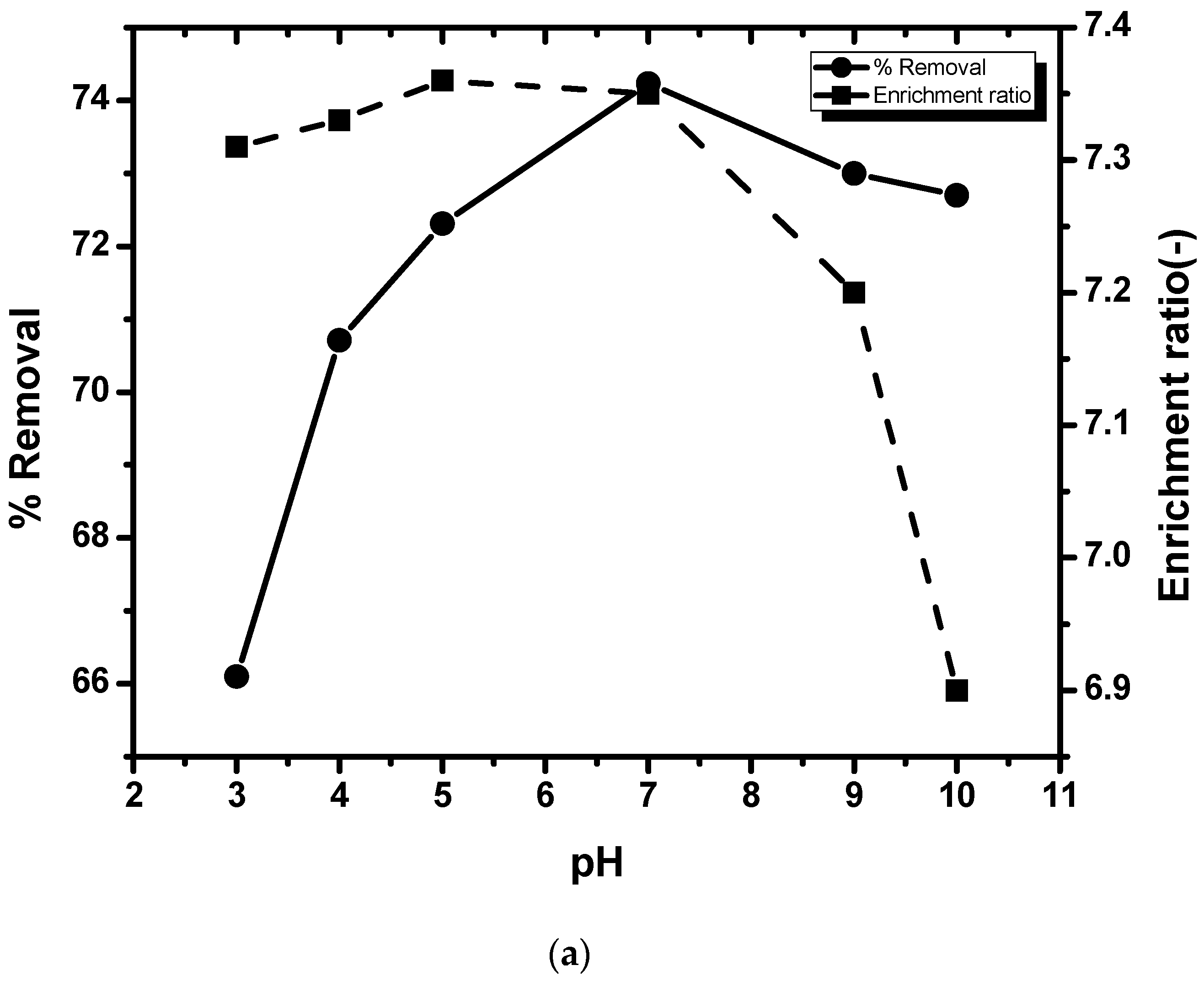
6.3. Effect of Initial pH

The pH of the feed solution dictates theamount of hydrogen and hydroxide ions that are instrumental in the generation of favorable dye-surfactant aggregate, hence is an important parameter for the efficacious separation of MB. Its influence on MB separation is depicted in Figure 5. Varying amounts of either 0.5 N HCl or 0.5 N NaOH were added to the feed solution to obtain different pH values. The pH of the aqueous feed solution varied from 3–10 when SDS, as a collector, was employed for performing the separation experiments. The percentage dye removal witnessed a rise followed by a dip when the initial pH of the feed was increased but at the same time, the enrichment ratio didn’t vary much (Figure 5a). Low pH (acidic conditions) favor the formation of H+ ions which compete with the cationic dye and hence provide hindrance in the production of dye-surfactant network, resulting in reduced dye removal. Moreover, greater amounts of hydroxide ions (high pH), owing to competition with an anionic surfactant, retards dye-surfactant network production which also leads to the decline in percentage removal. Further, alkalinity tends to cause foam wetness to rise which may also be the rationale behind lesser dye removal. It is visible from Figure 5a that the initial pH of 7 provided the highest percentage removal of MB. Hence, the optimum value of the initial pH to be maintained was fixed at 7 in all the subsequent separation experiments. The natural pH of the feed solutions at various MB concentrations with 500 ppm SDS was found to be in the range of 6.5–7.5, as a result of which no pH control technique was adopted in maintaining the pH of a solution.
The variation in separation parameters with the initial pH of a feed solution using SDBS as a surfactant also followed a similar trend (Figure 5b). The optimum pH of the feed solution was found to be near 9.5. Here, also no pH control method was utilized as the normal pH of the feed solutions at varying MB concentrations with 1000 ppm SDBS was between 9.5–11.

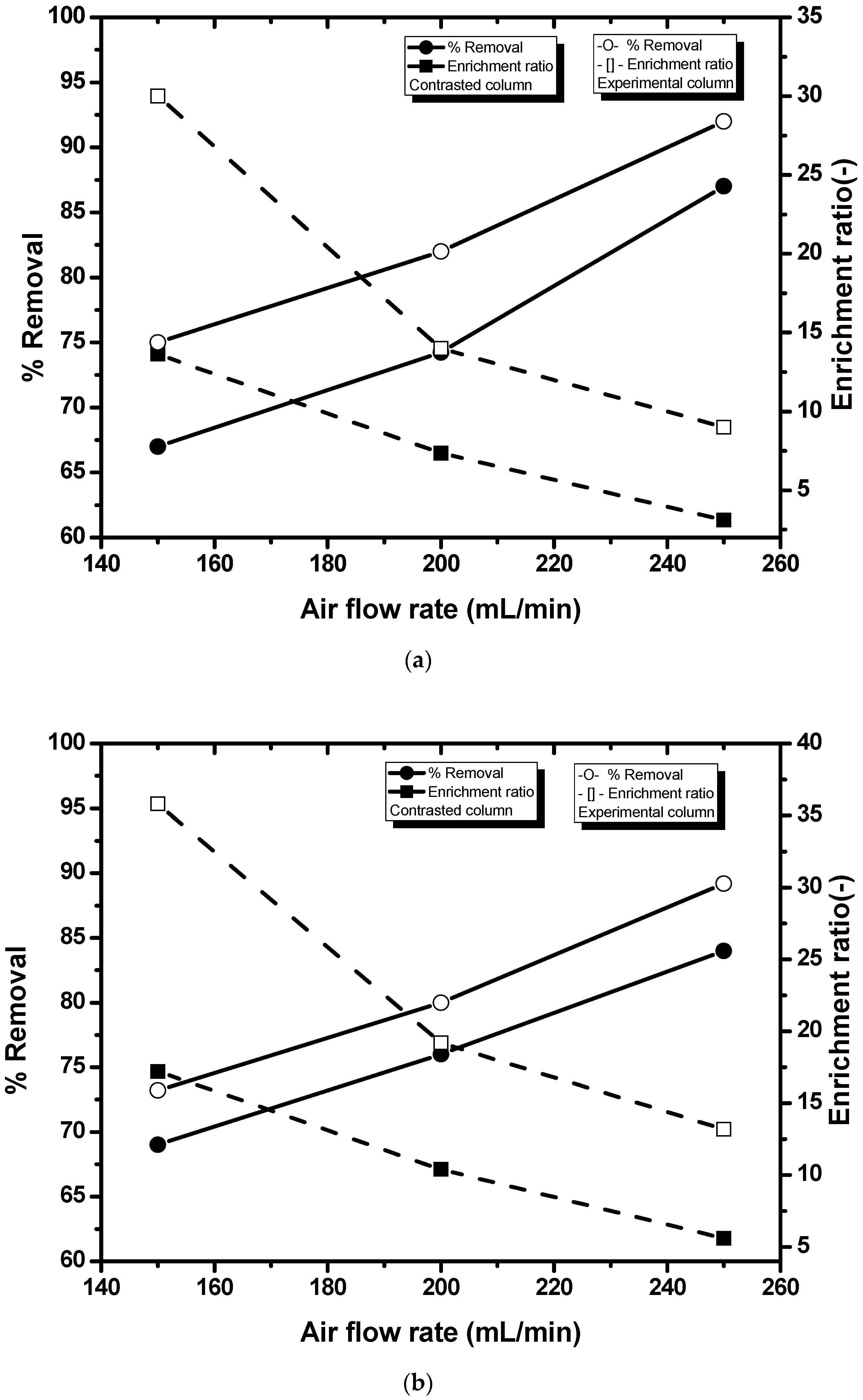
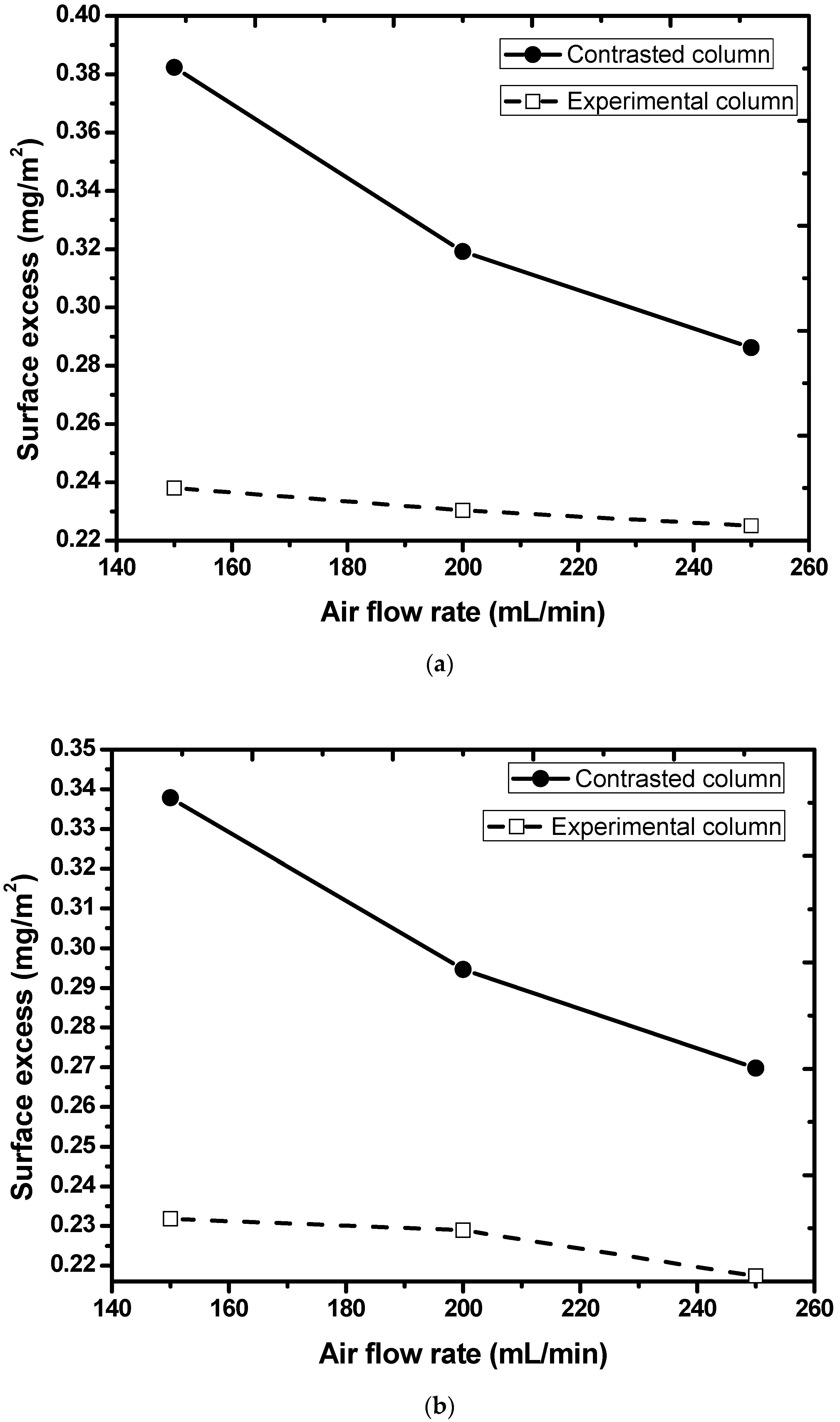
6.4. Effect of Air Flow Rate

The volumetric flow rate of air influences the diameter of the air bubble as well as the number of bubbles generated when it flows through the liquid solution. The bubble diameter as well as the quantity of bubbles has a direct bearing on all the separation parameters. The column was made to operate at varying air flow rates ranging from 150–250 mL·min−1 after charging 750 mL feed solution containing 15 ppm MB in it. The effect on separation parameters is shown in Figure 6 for both columns and surfactants.
The rise in MB removal (in %) and drop in enrichment ratio (Figure 6) was observed on increasing the flow rate of air. The higher flow rates caused the bubble diameter, the total number of bubbles, and hence the total surface area of bubbles generated in a given time to increase. It further led to a greater amount of dye adsorption due to which the percentage removal of dye registered an upward trend. On the contrary, the enrichment ratio fell as wet foam that emerged from the top of the column could not get enough time for the ejection of interstitial liquid at higher flow rates.
The values of surface excess were also found at various volumetric flow rates and are shown in Figure 7. Greater air flow rates through the liquid solution caused (i) the amount of dye adsorption to increase on account of the greater volume of foamate obtained, and (ii) the total surface area of the bubbles to rise. These two factors led the values of surface excess to fall (Equation (4)). The presence of a greater amount of interstitial liquid in the foam at higher airflow rates yielded enhanced values of foam wetness.

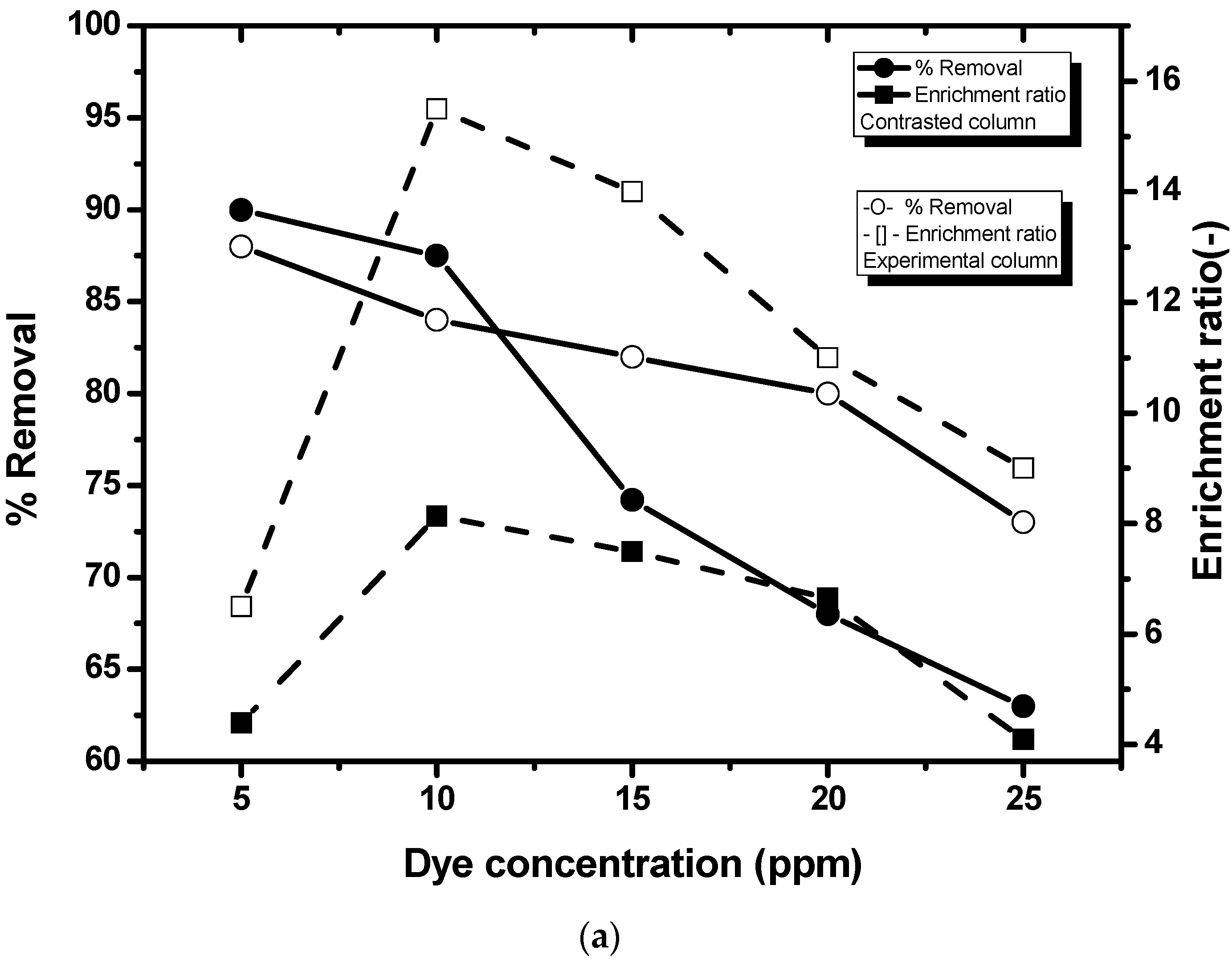
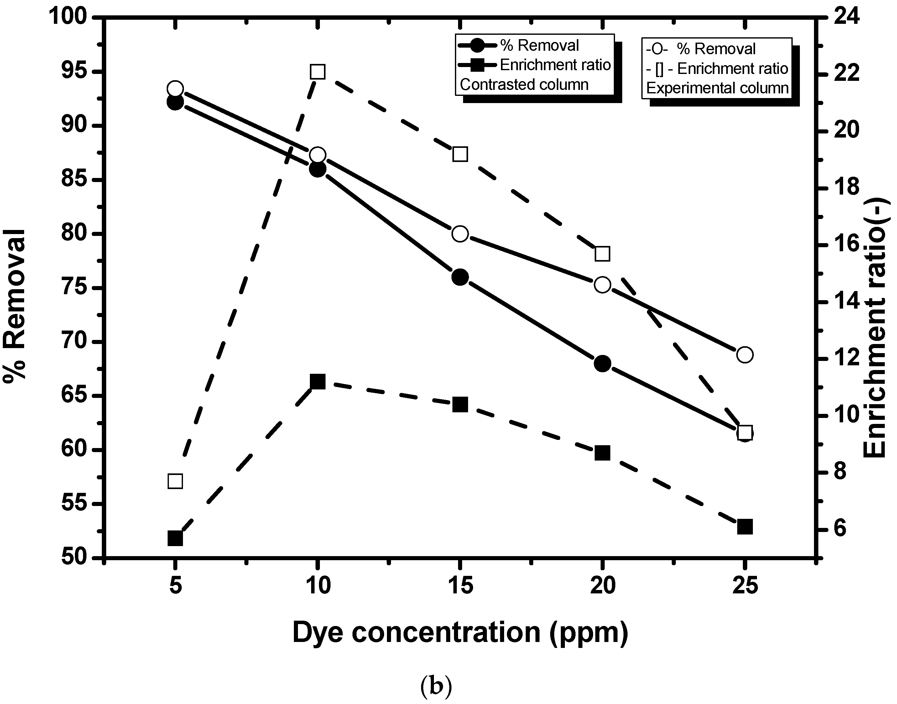
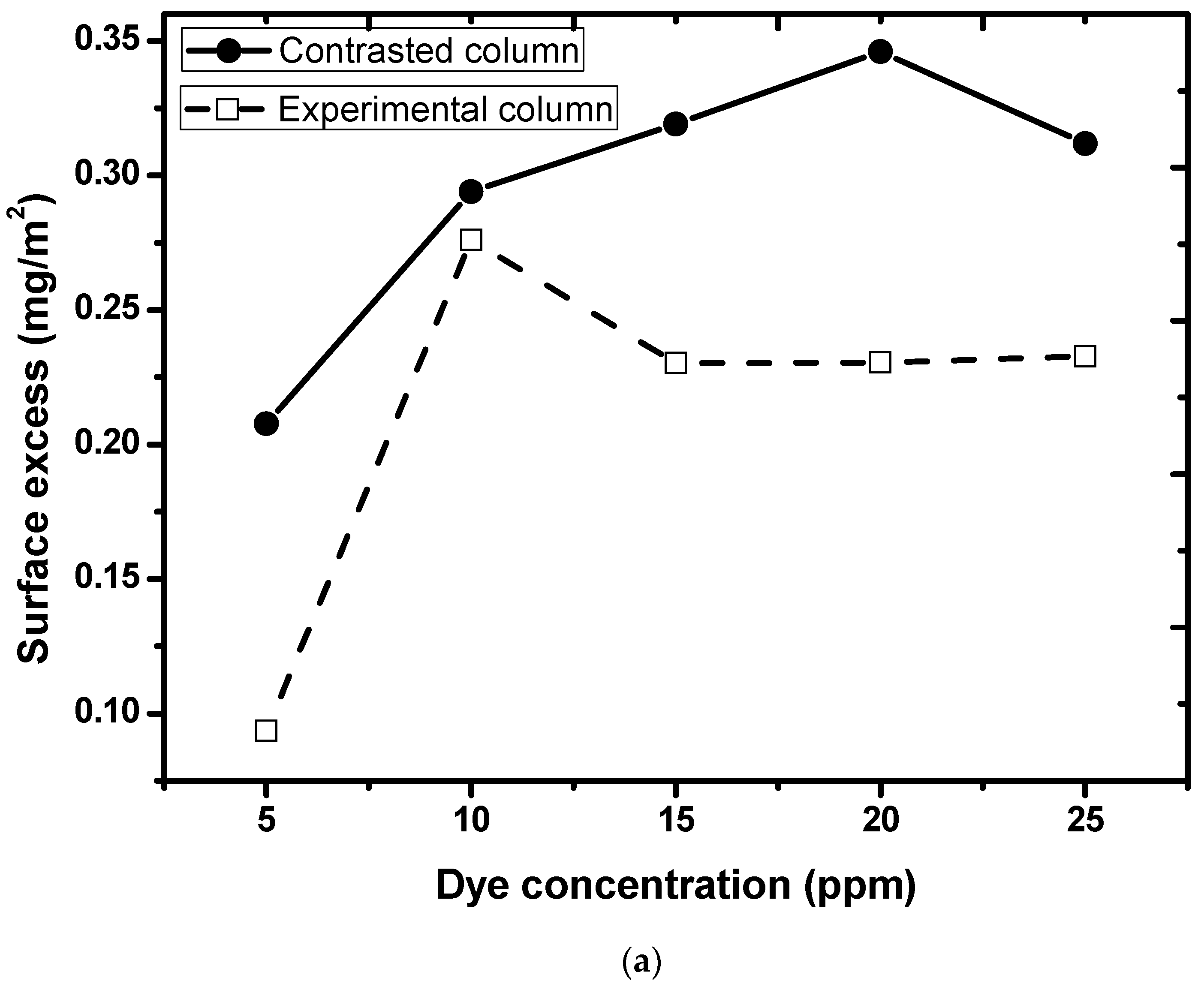
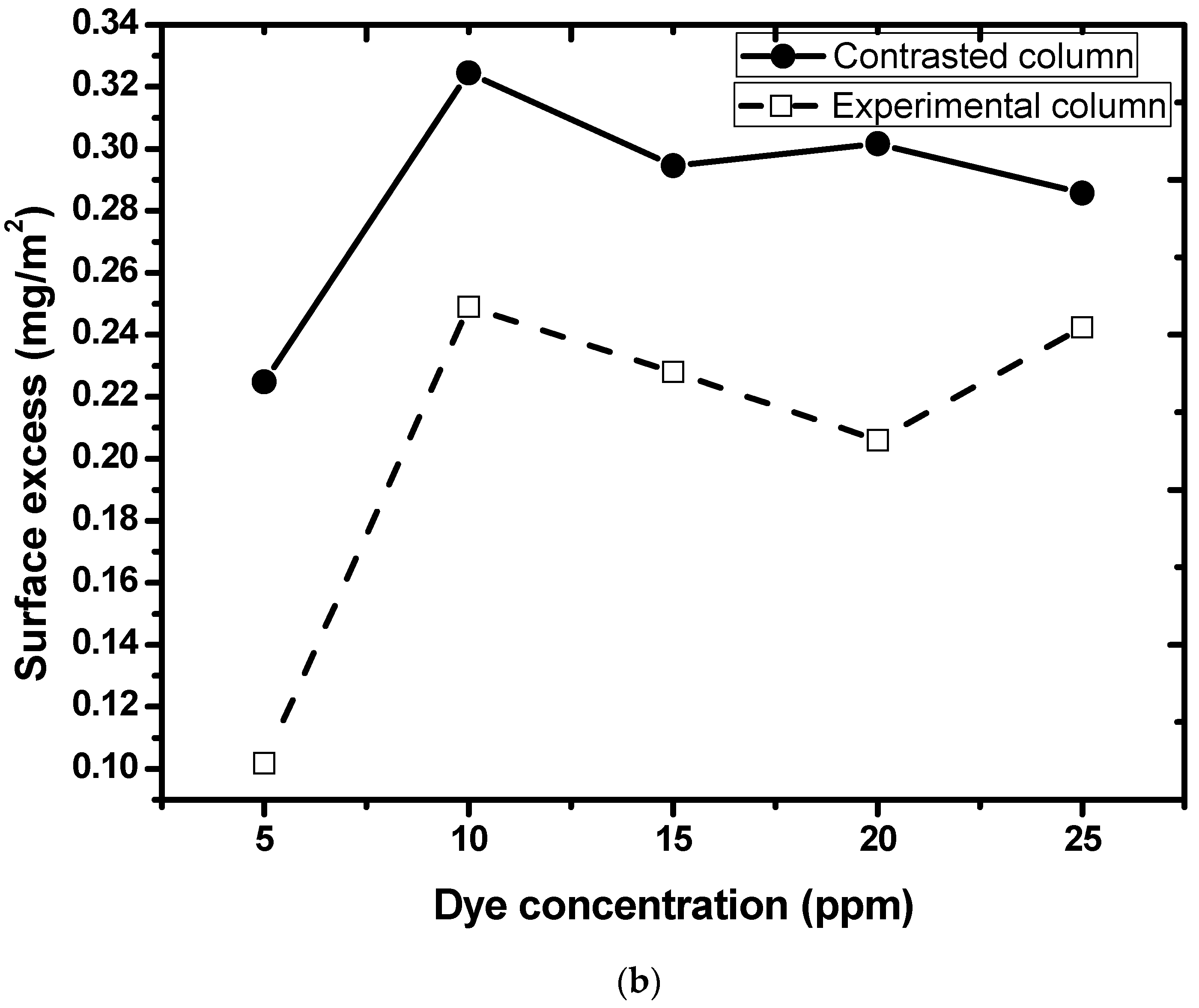
6.5. Effect of MB Concentration

The MB concentration dictates the amount of dye present in the column in a given volume which in turn influences the functioning of any foam fractionator. This investigation was performed by allowing air bubbles to flow at 200 mL·min−1 through a liquid solution (750 mL) in which the MB concentration was varied from 5–25 ppm. Figure 8 shows how the separation parameters change upon altering the concentration of a dye.
The percentage removal of dye declined with the increase in MB concentration in the liquid column. This is due to the lesser uptake of dye molecules on the air bubbles as the column is operated for a fixed period of time. The drop in the enrichment ratio was observed on raising the MB concentration from 10–25 ppm. Higher MB concentrations induce higher viscosity of interstitial liquid owing to which foam drainage gets hindered with the subsequent rise in enrichment ratio. An extremely low value of enrichment ratio was noted when a feed solution containing 5 ppm MB concentration was treated as the dye got exhausted after 25 min of column operation.
The variation in surface excess due to a change in MB concentration is demonstrated in Figure 9. There was no particular trend (increasing or decreasing) observed in the values of surface excess. It was due to the fact that surface excess being foamate concentration dependent did not follow any specific pattern on account of varying inlet dye concentrations. Similarly, foam wetness vs. dye concentration did not obey any specific trend as foam wetness is highly dependent on the foamate volume obtained in a specified time which is influenced by the concentration of MB in the foam phase.

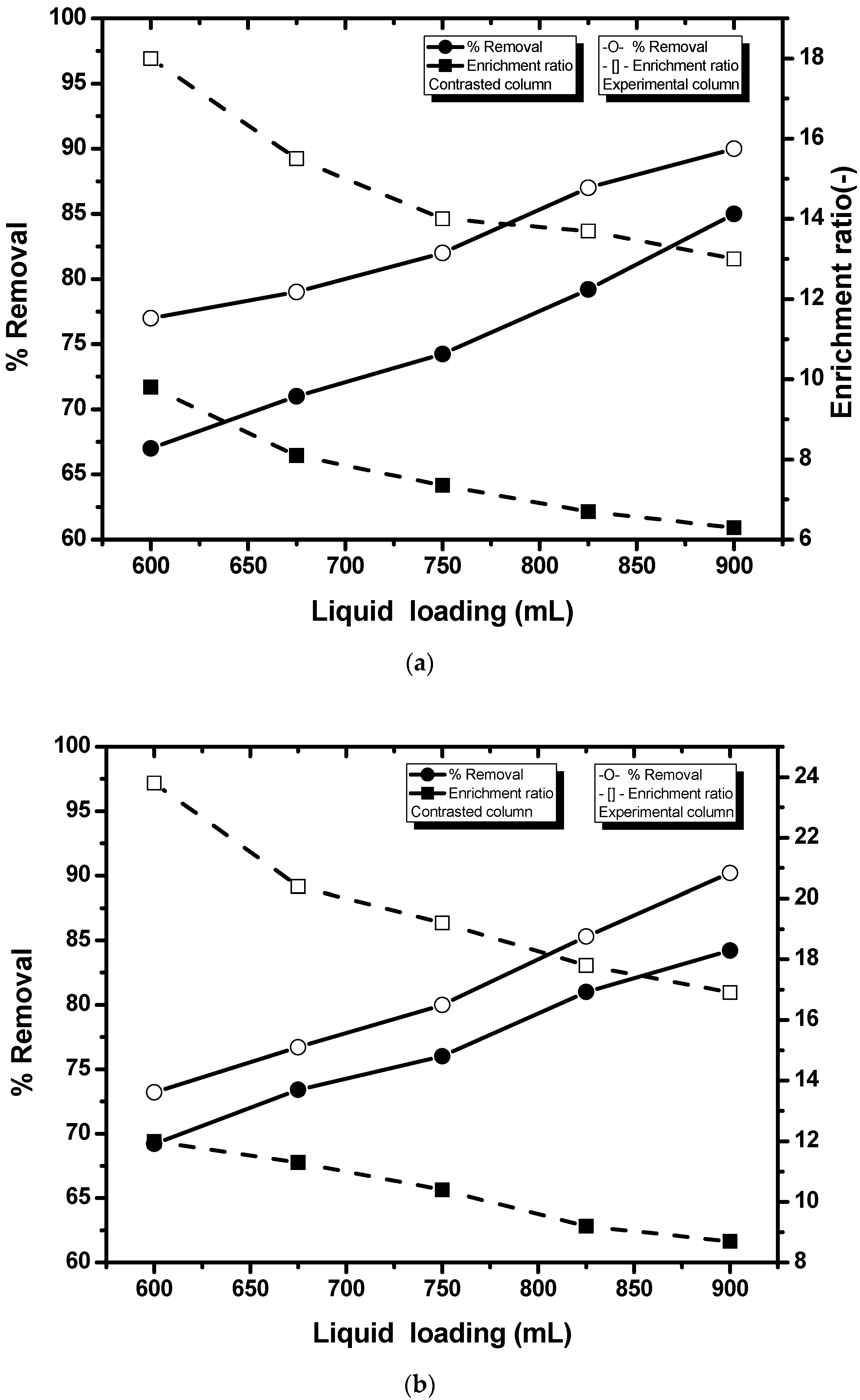
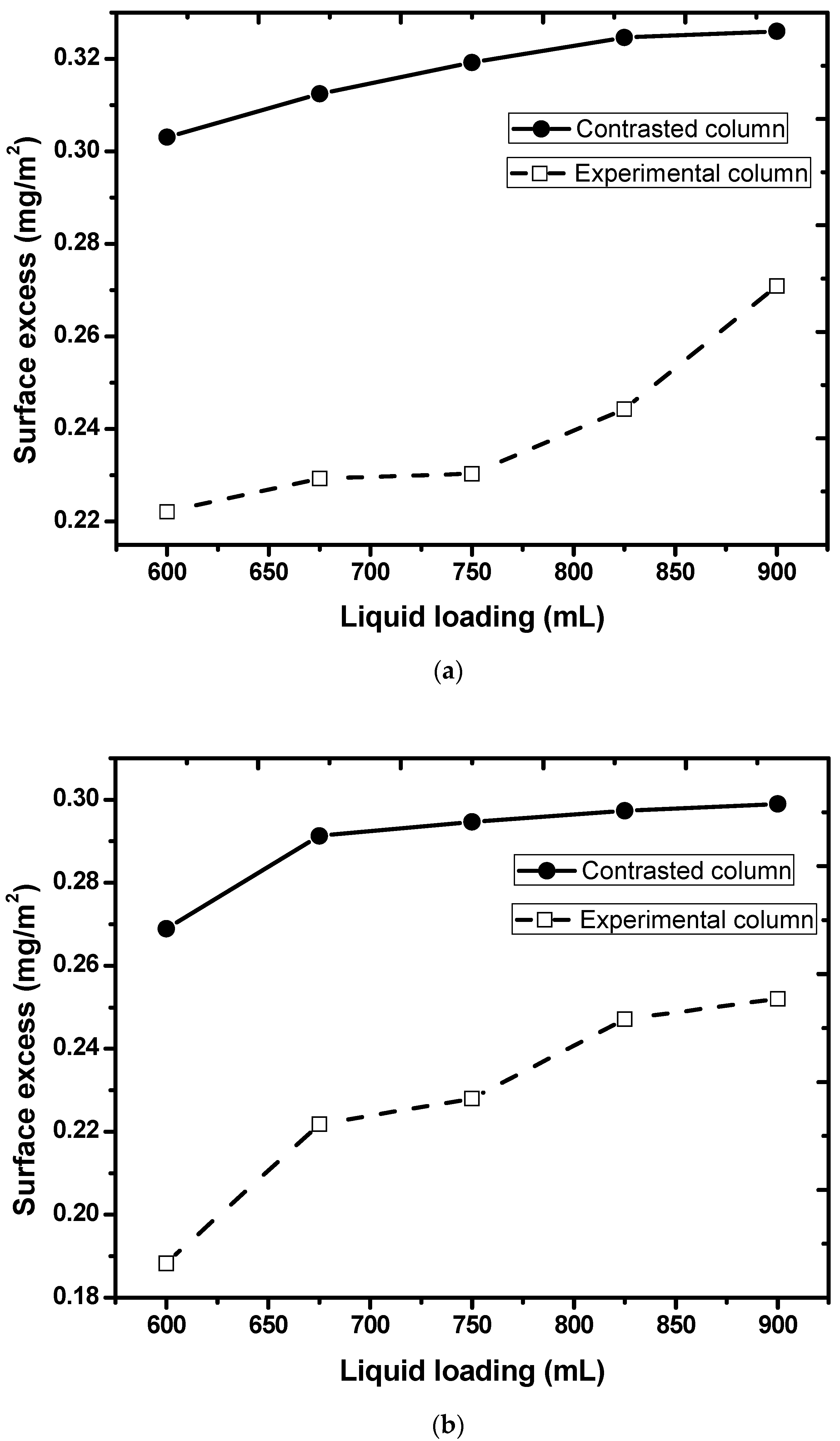
6.6. Effect of Liquid Loading

The volume of a liquid solution to be treated influences the mass of dye present in the dyeing wastewater. Hence it is considered to be one of the vital parameters for a foam fractionator. This investigation was undertaken by introducing air bubbles at the base of the column (200 mL·min−1) through a feed solution containing 15 ppm MB at varying liquid loadings (600–900 mL), shown in Figure 10.
The increment in contact time between dye solution and air bubbles at higher liquid loadings resulted in greater uptake of dye molecules which later led to the increase in dye removal. The enrichment ratio witnessed a dip owing to the reduction in foam height which resulted in the emergence of wet foam from the column’s top.
Greater liquid volumes caused surface excess to increase (Figure 11). It was chiefly due to the greater amounts of foamate obtained in a given time. Likewise, the wetness of foam also rose at greater liquid loadings.

6.7. Comparison between Columns (Contrasted &Experimental) and Surfactants (SDS & SDBS)

The comparison, in terms of the performance of the foam fractionator, was then made between the two columns (contrasted vs. experimental) when separation experiments were carried out by employing SDS and SDBS as surfactants. The following inferences were derived based on experimental results:
(i)
The experimental column yielded higher values of enrichment ratio compared to the contrasted column for both surfactants.
(ii)
Higher values of enrichment ratio were obtained when experiments were conducted by using SDBS as a collector for both columns.
(iii)
Greater surface excess and foam wetness were obtained in the case of contrasted columns for both surfactants.
(iv)
Larger values of surface excess and foam wetness were achieved when SDS was used as a collector for both columns.

7. Optimization Studies

The optimization studies assume significance as they provide the values of operating variables at which optimum enrichment ratio and percentage removal can be achieved. Taguchi methodology was first implemented through which one response (enrichment ratio or % removal) at a time can be optimized. Apart from this, grey relational analysis (GRA) technique was employed for the simultaneous optimization of both responses.

7.1. Taguchi Methodology

The process industries nowadays are looking at potential solutions that can reduce manufacturing costs substantially without compromising product quality. Taguchi is one such technique that can optimize any industrial process by keeping the quality intact [40]. This methodology employs an orthogonal array for the design of experiments. The main features of this array are (i) simultaneous evaluation of the influence of various operating variables on the response, and (ii) it requires less number of experiments compared to full factorial design and box-behnken design [41]. Firstly, an array consisting of operating variables with their respective setting levels is picked followed by the determination of experimental responses and computation of an objective functionknown as signal-to-noise (S/N) ratio. Its analysis is based on any one of the quality characteristics: (i) the minimum-the-better, (ii) the maximum-the-better, or (iii) the nominal-the-better. The optimum conditions or settings are the one that yields desired S/N ratio. The quantitative significance of operating variables on the response is subsequently found by making use of a technique known as analysis of variance (ANOVA).
To apply the Taguchi methodology, the process variables, namely, air flow rate (150–250 mL·min−1), liquid loading (600–900 mL), and MB concentration (5–25 ppm) were considered. Three levels were taken for each operating variable, illustrated in Table 4. L9 orthogonal array was considered, shown in Table 5.

S/N Ratio for Percentage Removal and Enrichment Ratio

Prior to the calculation of the S/N ratio, the experimental responses (% removal and enrichment ratio) were recorded by carrying out the experiments listed in Table 5. These responses are illustrated in Table 6 and Table 7 for SDS and SDBS, respectively. Equations (6) and (7) were then used for the calculation of the S/N ratio ( η ) , taking into account the maximum-the-better category [42]
η = 10 l o g M . S . D
M . S . D = 1 m i = 1 m 1 R i 2
where M.S.D denotes the mean square deviation of the nine (m = 9) experimental responses ( R i ) with the value of i ranging from 1 to 9. The S/N values are also reported in Table 6 and Table 7. These tables indicate that the maximum values of the S/N ratio for both responses were obtained for the following experiments:
(i)
Enrichment ratio: Experiment no. 2 (both the surfactants and columns).
(ii)
% removal: Experiment no. 8 (SDS, contrasted column), experiment no. 9 (SDS, experimental column), and experiment no. 6 (SDBS, both columns).
The mean values of S/N ratios for both SDS and SDBS were then determined for all the operating variables at each level, shown in Table 8 and Table 9, respectively. Based on the maximum value of the mean S/N ratio, the following conclusions were made:
(i)
Optimum values for obtaining maximum % removal: airflow rate = 250 mL·min−1, liquid loading = 900 mL, and MB concentration = 5 ppm.
(ii)
Optimum values for obtaining maximum enrichment ratio: airflow rate = 150 mL·min−1, liquid loading = 600 mL, and MB concentration = 15 ppm.
(iii)
The concentration of MB in the feed solution and flow rate of air, among all the operating parameters, were found to be the most sensitive operating variables with respect to % removal and enrichment ratio, respectively.
ANOVA results suggested MB concentration and air flow rate to have greatest influence on % removal and enrichment ratio, respectively.
The next step was the confirmation tests to ensure that the values of the S/N ratio ( η e ) , determined from Equation (8), at optimum conditions have increased compared to S/N values mentioned in Table 6 and Table 7.
η e = η + i = 1 p η i η
Here, η i is the average S/N ratio determined at optimum operating conditions with the value of i ranging from 1 to 3 (number of operating variables). The comparison between experimental and predicted values of S/N is shown in Table 10 and Table 11. It also indicates the augmentation in the values of both responses when experiments were conducted at optimum values of operating variables.

7.2. Grey Relational Analysis

Grey relational analysis (GRA) is used for the optimization of those processes that involve more than one response [43]. It involves the following stages: (i) normalization, (ii) estimation of (a) grey relational coefficient, and (b) grey relation grade [44]. The data is first normalized by making use of either of the following expressions depending on the kind of performance characteristic needed [45]:
The lower the better:
X i * k = m a x X i k X i k m a x X i k min X i k
The larger the better:
X i * k = X i k m i n X i k m a x X i k min X i k
The nominal the better:
X i * = 1 X i k X 0 b k m a x X i k X 0 b k
X i * k is the sequence obtained after performing the normalization of data. X i k is the initial sequence where max X i k is the maximum value in X i k , and min X i k is the minimum value in X i k . The value of i goes from 1 to 9 (number of experiments) and k goes from 1 to 2 (quality characteristics or responses).
The following expression is used to estimate the grey relational coefficient
ξ 0 , i k = m i n + ζ . m a x 0 , i k + ζ . m a x , i = 1 , . . n ; k = 1,2 . p .
where 0 , i k is the difference sequence compared to the initial one.
0 , i k = X 0 * k X i * k
m a x = max i max k X 0 * k X i * k
m i n = min i min k X 0 * k X i * k
The value of ζ , the distinguishing coefficient, in Equation (12) was taken as 0.5.

7.2.1. Weight Calculation

In order to quantify the importance of quality characteristics associated with the process, weight calculations are performed. Then, grey relational grade values’ are determined which is the basis for assigning ranks to all the experimental runs. Weights are calculated by employing the following mapping function based on the entropy measurement method:
w e x = x e 1 x + 1 x e x 1
Equation (16) yields 0.6478 as a maximum value of w e x when evaluated at x = 0.5, following which the expression for the entropy function is found to be:
W 1 e 0.5 1 n i = 1 n w e x i
The step-wise procedure for calculating grey relational grades is [46]:
(i)
Grey relational coefficients’ aggregate:
D j = i = 1 n ξ i j ,                 j = 1,2 , , p .
(ii)
Normalized coefficient:
k = 1 e 0.5 1 n = 1 0.6487 n
(iii)
Entropy:
e j = k i = 1 n w e ξ i j D j ,                 j = 1,2 , , p .
(iv)
Total entropy:
E = j = 1 p e j
(v)
Weight:
w j = 1 p E 1 e j j = 1 p 1 p E 1 e j ,                 i = 1,2 , p .
(vi)
Grey relational grade:
Γ 0 , i = k = 1 p w k ξ 0 , i k ,                 i = 1,2 , n .

7.2.2. Grey Relational Grade Analysis

Grey relational grade values were evaluated by utilizing Equations (12)–(23). Since greater values of both responses were required, Equation (10) was used for the purpose of normalization of data. The calculated grey relational grades’ values are reported in Table 12. These tables suggested the operating conditions, at which both responses were maximized simultaneously. The operating conditions of experiment No. 2 yielded the desired outcome for contrasted (SDS and SDBS) as well as an experimental column (SDS and SDBS). The mean grey relational grade values (Table 13 and Table 14) indicated MB concentration to be the most sensitive operating parameter. Finally, confirmation tests were conducted at the optimal values found in Table 13 and Table 14, the results of which are shown in Table 15 and Table 16.

8. Comparison with Earlier Studies

As already mentioned in the Section 1, there are only a few studies available on the removal of dyes in the literature using foam fractionation. Even though an attempt was made to compare experimental findings of the current work with the results of earlier investigations involving either MB or SDS, reported in Table 17. The percentage removal of dyes for all the studies listed in Table 17 was found to be greater than 95%.
The results obtained from the current study (Table 15 and Table 16) revealed an improvement in the values of the enrichment ratio compared to the earlier work (Table 17).

9. Cost Comparison—Foam Fractionation vs. Adsorption

The commercial viability of any removal process is a key parameter in the adoption of any technology. In this context, the cost comparison between foam fractionation and adsorption was performed as it is considered to be the most widely and commercially popular technique for the removal of dyes.A hypothetical scenario was presented wherein a factory generates 150 m3 of dyed wastewater per day for every metric ton of textile product produced [48]. The study compared the cost of two adsorbents i.e., diatomaceous earth and activated carbon required for the removal of MB dye. The cost of diatomaceous earth was found to be ₹304 for treating 1 m3 of dyeing wastewater and the removal by employing activated carbon incurred the cost six times higher (₹1824) compared to the diatomaceous earth.
Now, the costs incurred during the foam fractionation operation for the removal of MB dye using SDS and SDBS, respectively, in the present work have been worked out and are presented in Table 18.
It was evident from the cost comparison study that the cost of adsorbent in case of adsorption and the cost of surfactant in case of foam fractionation is the deciding factor in dictating the cost of a removal technique. The main advantage of foam fractionation over adsorption is the simultaneous removal and recovery of MB dye (foamate stream) whereas in adsorption, the adsorbed MB dye is recovered by performing another operation called desorption which further escalates the cost.

10. Conclusions

The isolation of MB by employing SDS and SDBS in the contrasted and experimental column was carried out. All the separation experiments were performed at optimum conditions to investigate the effect of other operating variables on enrichment ratio, percentage removal, surface excess, and foam wetness. The column contained higher liquid volumes with dilute concentrations of MB in it and when higher flow rates of air were allowed to pass through the liquid pool, percentage removal was found to increase. The enrichment ratio witnessed an increase when lesser liquid volumes with low MB concentrations and at low air flow rates were treated.
The enrichment ratio of MB using SDBS was found to be more but the amount of SDBS needed was greater in comparison to SDS. The concentration of MB in the foam phase was found to be around two times more when the same solution was processed in a contrasted column and it was achieved by inserting an inverted funnel in the column which is an economical enrichment technique as compared to other complex methods used by various researchers.
Taguchi methodology suggested that MB concentration has a maximum influence on percentage removal while air flow rate has a maximum influence on enrichment ratio.
The grey relational analysis yielded 150 mL·min−1 flow rate of air, 900 mL liquid volume, and 15 ppm MB concentration as optimum values of the operating variables for all the cases except 750 mL liquid loading when SDS was used as a surfactant in a contrasted column.
The key factor which decides the commercial viability of a foam fractionation technique is the cost of a surfactant required to be added to the dyeing wastewater.

Author Contributions

Conceptualization, K.N.G. and R.K.; methodology, K.N.G.; software, K.N.G. and A.K.T.; validation, K.N.G. and R.K.; formal Analysis, K.N.G.; investigation, K.N.G. and N.A.K.; resources, K.N.G.; data curation, K.N.G. and N.A.K.; writing—original draft preparation, K.N.G. and R.K.; writing—review & editing, K.N.G. and N.A.K.; visualization, K.N.G.; supervision, K.N.G.; project administration, K.N.G. All authors have read and agreed to the published version of the manuscript.

Funding

This research received no external funding.

Data Availability Statement

Not applicable.

Conflicts of Interest

The authors declare no conflict of interest.

References

  1. Abdi, J.; Vossoughi, M.; Mahmoodi, N.M.; Alemzadeh, I. Synthesis of metal-organic framework hybrid nanocomposites based on GO and CNT with high adsorption capacity for dye removal. Chem. Eng. J. 2017, 326, 1145–1158. [Google Scholar] [CrossRef]
  2. Valliammai, S.; Subbareddy, Y.; Nagaraja, K.S.; Jeyaraj, B. Removal of methylene blue from aqueous solution by activated carbon of Vigna Mungo L and Paspalum scrobiculatum: Equilibrium, kinetics and thermodynamic studies. Indian J. Chem. Technol. 2017, 24, 134–144. [Google Scholar]
  3. Gupta, V.K.; Suhas. Application of low-cost adsorbents for dye removal—A review. J. Environ. Manag. 2009, 90, 2313–2342. [Google Scholar] [CrossRef] [PubMed]
  4. Ahmadian, M.; Jaymand, M. Interpenetrating polymer network hydrogels for removal of synthetic dyes: A comprehensive review. Coord. Chem. Rev. 2023, 486, 215152. [Google Scholar] [CrossRef]
  5. Kausar, A.; Zohra, S.T.; Ijaz, S.; Iqbal, M.; Iqbal, J.; Bibi, I.; Nouren, S.; Messaoudi, N.E.; Nazir, A. Cellulose-based materials and their adsorptive removal efficiency for dyes: A review. Int. J. Biol. Macromol. 2023, 224, 1337–1355. [Google Scholar] [CrossRef] [PubMed]
  6. Gadekar, M.R.; Ahammed, M.M. Modelling dye removal by adsorption onto water treatment residuals using combined response surface methodology-artifical neural network approach. J. Environ. Manag. 2019, 231, 241–248. [Google Scholar]
  7. Moradi, O.; Panahandeh, S. Fabrication of different adsorbents based on zirconium oxide, graphene oxide, and dextrin for removal of green malachite dye from aqueous solutions. Environ. Res. 2022, 214, 114042. [Google Scholar] [CrossRef]
  8. Ikram, M.; Naeem, M.; Zahoor, M.; Hanafiah, M.M.; Oyekanmi, A.A.; Ullah, R.; Alfarraz, D.A.; Elshikh, M.S.; Zekker, I.; Gulfam, N. Biological degradation of the azo dye basic orange 2 by escherichia coli: A sustainable and ecofiendy approach for the treatment of textile wastewater. Water 2022, 14, 2063. [Google Scholar] [CrossRef]
  9. Ikram, M.; Naeem, M.; Zahoor, M.; Rahim, A.; Hanafiah, M.M.; Oyekanmi, A.A.; Shah, A.B.; Mahnashi, M.H.; Ali, A.A.; Jalal, N.A.; et al. Biodegradation of azo dye methyl red by pseudomonas aeruginosa: Optimization of process conditions. Int. J. Environ. Res. Public Health 2022, 19, 9962. [Google Scholar] [CrossRef]
  10. Yadav, J.; Sahu, O. Dye removal of cationic dye from aqueous solution through acid functionalized ceramic. Total Environ. Res. Themes 2023, 6, 100038. [Google Scholar] [CrossRef]
  11. Wang, C.; Wang, Y.; Shi, W.D.; Yan, W.C. Electric field assisted assembly of nanoparticle loaded microspheres toward industrial applications for organic dye removal. Sep. Purif. Technol. 2023, 306, 122565. [Google Scholar] [CrossRef]
  12. Tang, L.; Yu, J.; Pang, Y.; Zeng, G.; Deng, Y.; Wang, J.; Ren, X.; Ye, S.; Peng, B.; Feng, H. Sustainable efficient adsorbent: Alkali-acid modified magnetic biochar derived from sewage sludge for aqueous organic contaminant removal. Chem. Eng. J. 2018, 336, 160–169. [Google Scholar] [CrossRef]
  13. Hethnawi, A.; Nassar, N.N.; Manasrah, A.D.; Vitale, G. Polyethylenimine-functionalized pyroxene nanoparticles embedded on diatomite for adsorptive removal of dye from textile wastewater in a fixed-bed column. Chem. Eng. J. 2017, 320, 389–404. [Google Scholar] [CrossRef]
  14. Joshi, M.; Bansal, R.; Purwar, R. Colour removal from textile effluents. Indian J. Fibre Text. Res. 2003, 29, 239–259. [Google Scholar]
  15. Al-Alwani, M.A.M.; Norasikin, A.L.; Mohamad, A.B.; Kadhum, A.A.H.; Mukhlus, A. Applications of dyes extracted from Alternanthera Dentata leaves and Musa Acuminata Bracts as natural sensitizers for dye-sensitized solar cells. Spectrochim. Acta A Mol. Biomol. 2018, 192, 487–498. [Google Scholar] [CrossRef] [PubMed]
  16. Khan, N.A.; Bhadra, B.N.; Jhung, S.H. Heteropoly acid-loaded ionic liquid@metal-organic frameworks: Effective and reusable adsorbents for the desulfurization of a liquid model fuel. Chem. Eng. J. 2018, 334, 2215–2221. [Google Scholar] [CrossRef]
  17. Smith, S.J.; Lewis, J.; Wiberg, K.; Wall, E.; Ahrens, L. Foam fractionation for removal of per- and polyfluoroalkyl substances: Towards closing the mass balance. Sci. Total Environ. 2023, 871, 162050. [Google Scholar] [CrossRef] [PubMed]
  18. Lockwood, C.E.; Bummer, P.M.; Jay, M. Purification of proteins using foam fractionation. Pharm. Res. 1997, 14, 1511–1515. [Google Scholar] [CrossRef]
  19. Brown, A.K.; Kaul, A.; Varley, J. Continuous foaming for protein recovery. Part II. Selective recovery of proteins form binary mixtures. Biotechnol. Bioeng. 1999, 62, 291–300. [Google Scholar] [CrossRef]
  20. Rujirawanich, V.; Chavadej, S.; O’Haver, J.H.; Rujiravanit, R. Removal of trace Cd2+ using continuous multistage ion foam fractionation: Part I-The effect of feed SDS/Cd molar ratio. J. Hazard. Mater. 2010, 182, 812–819. [Google Scholar] [CrossRef]
  21. Boonyasuwat, S.; Chavadej, S.; Malakul, P.; Scamehorn, J.F. Anionic and cationic surfactant recovery from water using a multistage foam fractionator. Chem. Eng. J. 2003, 93, 241–252. [Google Scholar] [CrossRef]
  22. Backleh, M.; Ekici, P.; Leupold, G.; Coelhan, M.; Parlar, H. Quantitative enrichment of gingerols from ginger (Zingiber officinale Rose.) by isoelectric focussed adsorptive bubble chromatography (IFBAC). Adv. Food Sci. 2003, 25, 2–7. [Google Scholar]
  23. Buckley, T.; Karanam, K.; Han, H.; Vo, H.N.P.; Shukla, P.; Firouzi, M.; Rudolph, V. Effect of different co-foaming agents on PFAS removal from the environment by foam fractionation. Water Res. 2023, 230, 119532. [Google Scholar] [CrossRef]
  24. Rajabi, H.; Grassia, P. Transport of soluble surfactant on and within a foam film in the context of a foam fractionation process. Chem. Eng. Sci. 2023, 265, 118171. [Google Scholar] [CrossRef]
  25. Keshavarzi, B.; Krause, T.; Sikandar, S.; Schwarzenberger, K.; Eckert, K.; Ansorge-Schumacher, M.B.; Heitkam, S. Protein enrichment by foam Fractionation: Experiment and modeling. Chem. Eng. Sci. 2022, 256, 117715. [Google Scholar] [CrossRef]
  26. Buckley, T.; Karanam, K.; Xu, X.; Shukla, P.; Firouzi, M.; Rudolph, V. Effect of mono- and di-valent cations on PFAS removal from water using foam fractionation—A modelling and experimental study. Sep. Purif. Technol. 2022, 286, 120508. [Google Scholar] [CrossRef]
  27. Lu, K.; Zhang, X.L.; Zhao, Y.L.; Wu, Z.L. Removal of color from textile dyeing wastewater by foam fractionation. J. Hazard. Mater. 2010, 182, 928–932. [Google Scholar] [CrossRef]
  28. Varade, D.; Carriere, D.; Arriaga, L.R.; Fameau, A.L.; Rio, E.; Langevin, D.; Drenckhan, W. On the origin of the stability of foams made from cationic surfactant mixtures. Soft Matter 2011, 7, 6557. [Google Scholar] [CrossRef]
  29. Lu, K.; Li, R.; Wu, Z.; Hou, K.; Du, X.; Zhao, Y. Wall effect on rising foam drainage and its application to foam separation. Sep. Purif. Technol. 2013, 118, 710–715. [Google Scholar] [CrossRef]
  30. Zhang, Z.; Wu, Z.; Liu, G. Interfacial adsorption of methyl orange in liquid phase of foam fractionation using dodecyl dimethyl betaine as the collector. J. Ind. Eng. Chem. 2015, 28, 184–189. [Google Scholar] [CrossRef]
  31. Zhang, D.; Zeng, G.; Huang, J.; Bi, W.; Gengxin, X. Spectroscopic studies of dye-surfactant interactions with the co-existence of heavy metal ions for foam fractionation. J. Environ. Sci. 2012, 24, 2068–2074. [Google Scholar] [CrossRef] [PubMed]
  32. Fei, X.; Li, W.; Zhu, S.; Liu, L.; Yang, Y. Simultaneous treatment of dye wastewater and surfactant wastewater by foam separation: Experimental and mesoscopic simulation study. Sep. Sci. Technol. 2017, 53, 1604–1610. [Google Scholar] [CrossRef]
  33. Shakir, K.; Elkafrawy, A.F.; Ghoneimy, H.F.; Beheir, S.G.E.; Refaat, M. Removal of rhodamine B (a basic dye) and thoron (an acidic dye) from dilute aqeuous solutions and wastewater simulants by ion flotation. Water Res. 2010, 44, 1449–1461. [Google Scholar] [CrossRef]
  34. Marvos, P.; Daniilidou, A.C.; Lazaridis, N.K.; Stergiou, L. Colour removal from aqueous solutions. Part I. Flotation. Environ. Technol. 1994, 15, 601–616. [Google Scholar]
  35. Li, X.; Evans, G.M.; Stevenson, P. Process intensification of foam fractionation by successive contraction and expansion. Chem. Eng. Res. Des. 2011, 89, 2298–2308. [Google Scholar] [CrossRef]
  36. Darton, R.C.; Supino, S.; Sweeting, K.J. Development of a multistaged foam fractionation column. Chem. Eng. Process. Process Intensif. 2004, 43, 477–482. [Google Scholar] [CrossRef]
  37. Stevenson, P.; Li, X.; Evans, G.M. A mechanism for internal reflux in foam fractionation. Biochem. Eng. J. 2008, 39, 590–593. [Google Scholar] [CrossRef]
  38. Li, H.; Wu, Z.; Liu, W.; Li, Z.; Hu, N.; Huang, D. Recovery of yam mucilage from the yam starch processing wastewater by using a novel foam fractionation column. Sep. Purif. Technol. 2016, 171, 26–33. [Google Scholar] [CrossRef]
  39. Huang, D.; Wu, Z.L.; Liu, W.; Hu, N.; Li, H.Z. A novel process intensification approach of recovering creatine from its wastewater by batch foam fractionation. Chem. Eng. Process. Process Intensif. 2016, 104, 13–21. [Google Scholar] [CrossRef]
  40. Bakhtiyari, N.; Wu, Y.; Wang, L.; Wang, Z.; Zheng, H. Laser machining sapphire via si-sapphire interface absorption and process optimization using an integrated approach of the taguchi method with grey relational anlaysis. J. Mater. Res. Technol. 2023, 24, 663–674. [Google Scholar] [CrossRef]
  41. Hayatzadeh, M.; Moosavi, V.; Alirarmaee, R. Assessment and prioritization of soil erosion triggering factors using analytical hierarchy process and taguchi method. Int. J. Sediment Res. 2023, 38, 396–404. [Google Scholar] [CrossRef]
  42. Tamang, M.; Paul, K.K. Adsorptive treatment of phenol from aqueous solution using chitosan/calcined eggshell adsorbent: Optimization of preparation process using Taguchi statistical analysis. J. Indian Chem. Soc. 2022, 99, 100251. [Google Scholar] [CrossRef]
  43. Mausam, K.; Pare, A.; Ghosh, S.K.; Tiwari, A.K. Thermal performance analysis of hybrid-nanofluid based flat plate collector using Grey relational analysis (GRA): An approach for sustainable energy harvesting. Therm. Sci. Eng. Prog. 2023, 37, 101609. [Google Scholar] [CrossRef]
  44. Almetwally, A.A. Muti-objective optimization of woven fabric parameters using taguchi-grey relational analysis. J. Nat. Fibers 2019, 17, 1468–1478. [Google Scholar]
  45. Jiang, X.; Wu, C.; Zhou, H.; Gao, B.; Fang, X.; Han, J.; Gao, W. Relationship between thermal properties and structure, composition of briquette through grey relational analysis. J. Appl. Geophys. 2022, 206, 104786. [Google Scholar] [CrossRef]
  46. Deng, D.; Li, T.; Huang, Z.; Jiang, H.; Yang, S.; Zhang, Y. Multi-response optimization of laser cladding for TiC particle reinforced Fe matrix composite based on Taguchi method and grey relational analysis. Opt. Laser Technol. 2022, 153, 108259. [Google Scholar] [CrossRef]
  47. Schwarze, M.; Gross, M.; Ebraheme, A.; Lima, M.T.; Uhling, M.; Klitzing, R.; Roeber, O.; Olschewski, B.; Schomacker, R. Biopolymers for dye removal via foam separation. Sep. Purif. Technol. 2017, 188, 451–457. [Google Scholar]
  48. Mumbi, A.W.; Watanabe, T. Cost estimations of water pollution for the adoption of suitable water treatment technology. Sustainability 2022, 14, 649. [Google Scholar] [CrossRef]
Figure 1. Molecular structure of methylene blue.
Water 15 02236 g001
Figure 2. Schematic diagram of the foam fractionation column: (a) contrasted; (b) experimental.
Water 15 02236 g002
Figure 3. Effect of contact time on percentage removal and enrichment ratio (Air flow rate = 200 mL·min−1, Liquid loading = 750 mL, Dye concentration = 15 ppm): (a) SDS concentration = 500 ppm; (b) SDBS concentration = 1000 ppm).
Water 15 02236 g003aWater 15 02236 g003b
Figure 4. Effect of surfactant dose on percentage removal and enrichment ratio (Air flow rate = 200 mL·min−1, Liquid loading = 750 mL, Dye concentration = 15 ppm): (a) SDS; (b) SDBS.
Water 15 02236 g004
Figure 5. Effect of pH on percentage removal and enrichment ratio (Air flow rate = 200 mL·min−1, Liquid loading = 750 mL, Dye concentration = 15 ppm): (a) SDS concentration = 500 ppm; (b) SDBS concentration = 1000 ppm).
Water 15 02236 g005aWater 15 02236 g005b
Figure 6. Effect of air flow rate onpercentage removal and enrichment ratio (Liquid loading = 750 mL, Dye concentration = 15 ppm): (a) SDS concentration = 500 ppm; (b) SDBS concentration = 1000 ppm.
Water 15 02236 g006
Figure 7. Effect of air flow rate onsurface excess (Liquid loading = 750 mL, Dye concentration = 15 ppm): (a) SDS concentration = 500 ppm; (b) SDBS concentration = 1000 ppm.
Water 15 02236 g007
Figure 8. Effect of dye concentration onpercentage removal and enrichment ratio (Air flow rate = 200 mL·min−1, Liquid loading = 750 mL): (a) SDS concentration = 500 ppm; (b) SDBS concentration = 1000 ppm.
Water 15 02236 g008aWater 15 02236 g008b
Figure 9. Effect of dye concentration onsurface excess (Air flow rate = 200 mL·min−1, Liquid loading = 750 mL): (a) SDS concentration = 500 ppm; (b) SDBS concentration = 1000 ppm.
Water 15 02236 g009aWater 15 02236 g009b
Figure 10. Effect of liquid loading onpercentage removal and enrichment ratio (Air flow rate = 200 mL·min−1, Dye concentration = 15 ppm): (a) SDS concentration = 500 ppm; (b) SDBS concentration = 1000 ppm.
Water 15 02236 g010
Figure 11. Effect of liquid loading onsurface excess (Air flow rate = 200 mL·min−1, Dye concentration= 15 ppm): (a) SDS concentration = 500 ppm; (b) SDBS concentration = 1000 ppm.
Water 15 02236 g011
Table 1. List of researchers who did work in the field of removal of dyes.
Name of DyeReference
Removal of color using CTAB[27]
Removal of crystal violet using SDS[29]
Removal of methyl orange using dodecyl dimethyl betaine[30]
Removal of MB using SDS in the presence of Cd2+[31]
Removal of rhodamine B and CTAB/SDBS[32]
Removal of rhodamine B and thoron using NaLS and CTAB[33]
Removal of basic yellow 28, direct black 22, and disperse orange 30 using NaLS, sodium oleate, and dodecylamine[34]
Table 2. Operating variables with their respective ranges.
S. No.Operating VariableUnitsRange
1Contact timeminutes10–45
2Surfactant concentrationppmSDS (300–2000 ppm) and SDBS (800–1200 ppm)
3Initial pH of the solution-SDS (3–10) and SDBS (3–11)
4Aeration ratemL·min−1150–250
5Liquid loadingmL600–900
6Dye concentrationppm5–25
Table 3. Range of dye concentrations used in earlier studies.
S. No.DyeConcentration (ppm)Reference
1Crystal Violet10[29]
2Methyl Orange10–50[30]
3Methylene Blue10[31]
4Rhodamine B15[32]
Table 4. Operating parameters and their levels.
SymbolOperating ParametersLevel 1Level 2Level 3
AAir flow rate (mL·min−1)150200250
BLiquid loading (mL)600750900
CDye concentration (ppm)51525
Table 5. Experimental layout using an L9 orthogonal array.
Experiment No.Operating Parameters
Air Flow RateLiquid LoadingDye Concentration
1111
2122
3133
4212
5223
6231
7313
8321
9332
Table 6. Experimental results for percentage removal and enrichment ratio along with S/N ratio using SDS.
Experiment No.Air Flow Rate (mL·min−1)Liquid Loading (mL)Dye Concentration (ppm)Percentage Removal (S/N Ratio)Enrichment Ratio
(S/N Ratio)
Contrasted column
1150600576.2 (37.63)9.2 (19.27)
21507501567 (36.52)13.63 (22.68)
31509002568.3 (36.68)6.5 (16.25)
42006001567 (36.52)9.8 (19.82)
52007502563 (35.98)3.9 (11.82)
6200900593.2 (39.38)3.8 (11.59)
72506002564.2 (36.15)2.37 (7.49)
8250750596 (39.64)1.84 (5.29)
92509001592.4 (39.31)2.8 (8.94)
Experimental column
1150600579.7 (38.02)15.2 (23.63)
21507501575 (37.50)30 (29.54)
31509002574.2 (37.40)17 (24.60)
42006001577 (37.72)18 (25.10)
52007502573 (37.26)9 (19.08)
6200900592 (39.27)5.2 (14.32)
72506002577.3 (37.76)8.7 (18.79)
8250750592.5 (39.32)3.4 (10.62)
92509001597.4 (39.77)7 (16.90)
Table 7. Experimental results for percentage removal and enrichment ratio along with S/N ratio using SDBS.
Experiment No.Air Flow Rate (mL·min−1)Liquid Loading (mL)Dye Concentration (ppm)Percentage Removal (S/N Ratio)Enrichment Ratio
(S/N Ratio)
Contrasted column
1150600578.4 (37.88)9.8 (19.82)
21507501569 (36.77)17.2 (24.71)
31509002570.5 (36.96)10.5 (20.42)
42006001569.2 (36.80)12 (21.58)
52007502561.5 (35.77)6.1 (15.70)
6200900596.2 (39.66)4.3 (12.66)
72506002564.5 (36.19)5.1 (14.15)
8250750595.7 (39.61)2.1 (6.44)
92509001593 (39.36)4.8 (13.62)
Experimental column
1150600580.5 (38.11)19.2 (25.66)
21507501573.2 (37.29)35.8 (31.07)
31509002575 (37.50)18.7 (25.43)
42006001573.2 (37.29)23.8 (27.53)
52007502568.8 (36.75)9.4 (19.46)
6200900599.1 (39.92)6.1 (15.70)
72506002567.2 (36.54)9.7 (19.73)
8250750598.3 (39.85)3.6 (11.12)
92509001596.4 (39.68)9.6 (19.64)
Table 8. S/N response table for SDS.
SymbolOperating ParametersMean S/N Ratio (dB)
Level 1Level 2Level 3Max–Min
Percentage removal (contrasted column)
AAir flow rate36.9437.2938.36 *1.42
BLiquid loading36.7737.3838.46 *1.69
CDye concentration38.89 *37.4536.272.61
Enrichment ratio (contrasted column)
AAir flow rate19.40 *14.417.2412.16
BLiquid loading15.53 *13.2612.263.26
CDye concentration12.0517.15 *11.855.29
Percentage removal (experimental column)
AAir flow rate37.6438.0938.95 *1.30
BLiquid loading37.8438.0338.81 *0.97
CDye concentration38.87 *38.3337.471.39
Enrichment ratio (experimental column)
AAir flow rate25.92 *19.5015.4410.48
BLiquid loading22.51 *19.7518.613.90
CDye concentration16.1923.84 *20.827.65
Note: * Optimum value.
Table 9. S/N response table for SDBS.
SymbolOperating ParametersMean S/N Ratio (dB)
Level 1Level 2Level 3Max–Min
Percentage removal (contrasted column)
AAir flow rate37.2037.4138.39 *1.18
BLiquid loading36.9537.3938.66 *1.70
CDye concentration39.05 *37.6436.312.74
Enrichment ratio (contrasted column)
AAir flow rate21.65 *16.6511.4010.24
BLiquid loading18.51 *15.6215.572.94
CDye concentration12.9719.97 *16.766.99
Percentage removal (experimental column)
AAir flow rate37.6337.9838.69 *1.05
BLiquid loading37.3137.9639.03 *1.07
CDye concentration39.29 *38.0836.932.36
Enrichment ratio (experimental column)
AAir flow rate27.39 *20.9016.8310.55
BLiquid loading24.31 *20.5520.264.04
CDye concentration17.4926.08 *21.548.58
Note: * Optimum value.
Table 10. Results of the confirmation experiments for SDS (Taguchi methodology).
Optimal Process Variables
PredictionExperiment
Percentage Removal (contrasted column)
Level A 3 B 3 C 1 A 3 B 3 C 1
% Removal-99.5
S/N ratio (dB)40.6439.95
Enrichment ratio (contrasted column)
Level A 1 B 1 C 2 A 1 B 1 C 2
Enrichment ratio-16.7
S/N ratio (dB)24.7124.45
Percentage Removal (experimental column)
Level A 3 B 3 C 1 A 3 B 3 C 1
% Removal-99.6
S/N ratio (dB)40.1839.96
Enrichment ratio (experimental column)
Level A 1 B 1 C 2 A 1 B 1 C 2
Enrichment ratio-38.3
S/N ratio (dB)31.7031.66
Table 11. Results of the confirmation experiments for SDBS (Taguchi methodology).
Optimal Process Variables
PredictionExperiment
Percentage Removal (contrasted column)
Level A 3 B 3 C 1 A 3 B 3 C 1
% Removal-99.6
S/N ratio (dB)40.7739.96
Enrichment ratio (contrasted column)
Level A 1 B 1 C 2 A 1 B 1 C 2
Enrichment ratio-20.4
S/N ratio (dB)27.0026.19
Percentage Removal (experimental column)
Level A 3 B 3 C 1 A 3 B 3 C 1
% Removal-99.7
S/N ratio (dB)40.8139.97
Enrichment ratio (experimental column)
Level A 1 B 1 C 2 A 1 B 1 C 2
Enrichment ratio-49.3
S/N ratio (dB)34.3633.85
Table 12. Grey relational grade (GRG) values along with the rank of each experiment.
S. No.SDS (Contrasted Column)SDS (Experimental Column)SDBS (Contrasted Column)SDBS (Experimental Column)
GRGRankGRGRankGRGRankGRGRank
10.51550.44260.49950.4776
20.69410.69310.71210.7081
30.41470.42970.47070.4447
40.48960.45350.49760.4825
50.35680.36190.37180.3628
60.60430.51140.66520.6572
70.34290.38180.36990.3589
80.652420.51330.63330.6253
90.57640.66620.59740.6044
Table 13. Response table for the grey relational grade (SDS).
SymbolInput ParametersAverage Grey Relational Grade
Level 1Level 2Level 3Max–Min
Contrasted column
AAir flow rate0.541 *0.4830.5230.058
BLiquid loading0.4490.567 *0.5320.118
CDye concentration0.590 *0.5870.3710.219
Experimental column
AAir flow rate0.521 *0.4420.5200.079
BLiquid loading0.4250.5220.535 *0.109
CDye concentration0.4890.604 *0.3900.213
Note: * Optimum value.
Table 14. Response table for the grey relational grade (SDBS).
SymbolInput ParametersAverage Grey Relational Grade
Level 1Level 2Level 3Max–Min
Contrasted column
AAir flow rate0.560 *0.5110.5330.049
BLiquid loading0.4550.5720.577 *0.122
CDye concentration0.5990.602 *0.4030.198
Experimental column
AAir flow rate0.543 *0.5000.5290.042
BLiquid loading0.4390.5650.568 *0.128
CDye concentration0.5860.598 *0.3880.209
Note: * Optimum value.
Table 15. Results of the confirmation experiments using SDS (Grey relational analysis).
Optimal Process Variables
PredictionExperiment
Contrasted column:
Level A 1 B 2 C 1 A 1 B 2 C 1
% Removal-84.2
Enrichment ratio-8.4
Grey relational grade0.6670.555
Experimental column:
Level A 1 B 3 C 2 A 1 B 3 C 2
% Removal-82.5
Enrichment ratio-26.2
Grey relational grade0.6720.622
Table 16. Results of the confirmation experiments using SDBS (Grey relational analysis).
Optimal Process Variables
PredictionExperiment
Contrasted column:
Level A 1 B 3 C 2 A 1 B 3 C 2
% Removal-82.1
Enrichment ratio-15.7
Grey relational grade0.6700.701
Experimental column:
Level A 1 B 3 C 2 A 1 B 3 C 2
% Removal-84.3
Enrichment ratio-29.2
Grey relational grade0.6610.619
Table 17. Earlier investigations involving either MB or SDS.
S. No.ObjectiveResultReference
1Removal of crystal violet dye using SDS as a surfactant.Enrichment ratio = 4.12 without cross internal and 16.5 with cross internal. (Conditions: SDS concentration = 200 mg·L−1, air flow rate = 200 mL·min−1) [29]
2.Simultaneous removal of MB and Cd2+ using SDS as a surfactant in a continuous foam fractionation column.Enrichment ratios were found to reduce from 24.34 to 7.65 for MB and from 22.01 to 3.35 for Cd2+ on increasing the SDS concentration from 145 to 1440 mg·L−1.[31]
3.Removal of MB using a biopolymer, HeSat, as a collector.Enrichment ratio = 5 (Conditions: HeSat concentration = 500 mg·L−1, MB concentration = 10 mg·L−1, N2 flow rate = 13.4 mL·min−1) [47]
Table 18. Cost of foam fractionation operation, using SDS and SDBS.
S. No.SurfactantConcentration Used, ppmAmount Used in 750 mL Dye Solution, mgCost, ₹Cost for Treating 1 m3 of Dyeing Wastewater, ₹
1SDS5003750.33440
2SDBS10007501.52000
Disclaimer/Publisher’s Note: The statements, opinions and data contained in all publications are solely those of the individual author(s) and contributor(s) and not of MDPI and/or the editor(s). MDPI and/or the editor(s) disclaim responsibility for any injury to people or property resulting from any ideas, methods, instructions or products referred to in the content.

