1. Introduction
The experience of using the principles of ejection of water from underground and surface sources by combining a pump and jet apparatus has shown the effectiveness of their application, especially when it is necessary to increase the suction height of pumps [
1,
2,
3,
4].
As experimental data show, with an increase in the ejection coefficient, the water productivity increases. However, the critical value of ejection (0.85–0.95) does not allow a further increase in water flow, and therefore, this limit must be taken as the calculated one during design and operation [
2].
A positive example of ejection on the suction pipeline of vane (soil) pumps is pump–ejector installations widely used on dredgers and various water intake structures [
5,
6,
7,
8,
9]. Their use helps to increase the suction capacity of dredgers and reduce cavitation wear [
8].
The developed design of a double water jet pump [
10], as the main element of a closed circuit, is successfully used for pumping both clean and contaminated fluids from hydrogeological wells.
If it is necessary to clean the lifted liquid from various mechanical impurities or to take the water-ground mixture from the water source, additional water treatment devices are used, mainly in the form of hydrocyclones of various designs and operating modes [
11,
12,
13,
14,
15,
16,
17]. This is due to the fact that hydrocyclones are characterized by their high performance and ability to efficiently clean water from mechanical impurities at a relatively small size and cost, with low resource costs for operation. The results of measuring the parameters of the classification of suspended solid particles by size in a hydrocyclone equipped with an additional water injection mechanism show that such an arrangement significantly changes the characteristics of the hydrocyclone in a positive direction [
11]. This is confirmed by the results of another work on a similar topic [
12], which presents the hydrodynamic characteristics of a hydrocyclone equipped with a mechanism for additional water injection into the apparatus. The dependencies of the change in water flow through the drain pipes and the lower sand pipes are established.
In the conducted experimental studies, attention is mainly paid to the issue of achieving a high efficiency of separation of mechanical impurities from the liquid composition by improving the technology used [
13,
14,
15]. The article [
18] states that the excessive width of the flat bottom structure increases the number of large particles out of place in the overflow, which causes increased turbulence intensity.
To study the technological process and predict the separation of particles by size, as well as on the basis of these data to establish rational parameters of hydrocyclone devices, many works on mathematical, numerical, and computer modeling have been published [
19,
20,
21,
22,
23,
24,
25,
26,
27,
28]. In the article [
20] in particular, a search was made for a suitable turbulence model for hydrodynamic forecasts in industrial hydrocyclones. Here, the effect of turbulence on particles in hydrocyclones is analyzed by the dispersion index formula. It has been established that a hydrocyclone with a spiral inlet has a lower kinetic energy of turbulence and a more stable flow field compared to a traditional hydrocyclone with a tangential inlet [
23], and the tangential injection method has a stronger effect on the separation curve compared to the radial method [
24].
The results of the influence of various designs of the hydrocyclone inlet, drain pipe, and lower sand hole on the expected technological parameters are given and analyzed in scientific papers [
29,
30,
31,
32,
33,
34,
35]. As noted in [
31], the design of a hydrocyclone with a drain pipe supplemented with a bulk filter makes it possible to increase the efficiency of trapping mechanical impurities on 12% in comparison with a typical apparatus, and with an extended top drain, it has a closer profile to a quasi-rigid rotation. The bottom stream is usually adjusted to overcome variable feed conditions, thereby providing the desired performance [
36].
Issues of improving hydrocyclone performance by controlling the internal structure of turbulence and using a high-pressure hydrocyclone to classify particulate matter in the submicron range are considered to a fairly high degree in the articles [
37,
38]. As indicated in [
39,
40,
41], the separation capacity of hydrocyclones is also significantly affected by the correct choice of the lower flow line and the presence of an air core.
An important element in the research of hydrocyclone installations is the optimization of the structural and technological parameters of the hydrocyclone with the classification of small and large particles [
42,
43,
44]. At the same time, issues of reducing the abrasive wear of the hydrocyclone and pumping equipment, as well as energy costs, are relevant. The developments carried out in the Kazakh Research Institute of Water Management in this direction have shown that this issue can be effectively solved by creating a vacuum or pressure-vacuum mode of operation in hydrocyclones. To do this, the hydrocyclone is installed on the suction line of a centrifugal pump, and water is supplied to it using an ejector [
2,
45].
This arrangement of the hydrocyclone with the base pump and the action of the additional ejector on the cleaning process, to a certain extent, affects the nature of the change in the parameters of the working process. The results of the study of these features determine the scientific novelty of the studied pressure-vacuum regime in a hydrocyclone in comparison with the data of the analyzed literature.
2. Materials and Methods
A structural diagram of a catchment well equipped with an ejector and a hydrocyclone is shown in
Figure 1a [
2]. It consists of a catchment well 1, of a centrifugal pump 2, a hydrocyclone 3, an ejector 4, and a filter 5.
When the pump 1, located on the surface, is turned on, water is supplied under pressure to the working nozzle of the ejector 4. Due to the ejection pressure, the suction water enters the hydrocyclone 3 installed on the pump suction. The tangential entry of water into the hydrocyclone creates a swirling flow in which solid particles are separated from the composition of the water. In the adopted scheme, the hydrocyclone can operate in a pressure-vacuum mode, because a vacuum is formed in the zone of the hydrocyclone drain pipe due to the suction of the pump, and the residual pressure from the ejector is maintained in the cone part. The purified water is sucked in by the pump, and a certain part of it is transferred back under pressure to the ejector head as a working fluid.
Figure 1 shows a general view of the experimental stand for studying the main parameters of the developed installation.
Here, in addition to the above main elements of the installation, there is also a telescopic rack 6, with the help of which, the suction height of the pump is adjusted.
The hydrocyclone was made of Plexiglas, which provided visual observation of the process taking place in it. The ejector and the front part of the receiving tank 7 were also made transparent. Tank 8 with dimensions of 0.5 × 0.5 × 0.4 m3 was designed to determine the flow of water through the sand hole of the hydrocyclone.
The flow rate of water flowing out through the outlet of the hydrocyclone Q2 was set using an additional outlet 9. The installation was charged in two ways: by supplying water from the water supply to the installation or using an ejector 10 with an individual pump under flooding.
The pressure values at characteristic points (at the inlet of the hydrocyclone chamber P1, at the outlet of the hydrocyclone P2, at the discharge line of the pump Pp, and downstream of the ejector diffuser Pe) were set using pressure gauge 11 and vacuum gauge 12.
The static pressure field in the cross sections of the hydrocyclone chamber was established using a special probe with a cylindrical tip and a through-hole at the end.
The technological scheme of the stand in a closed cycle ensures the continuity of the testing of the installation for the intake and purification of the raised water.
In the first version of the study, the processes of pressure changes inside a cylindrical-conical hydrocyclone with accepted design dimensions (
Table 1) and the patterns of formation of vacuum and pressure-vacuum modes depending on the initial parameters were studied. In this case, the pressure gradients were recorded in the characteristic sections of the hydrocyclone, covering all the working areas of the cyclone flow.
The dimensions of the tested ejector were taken in the following values: the diameters of the working nozzle dp = 10 mm, the mixing chamber dmc = 24 mm, and the diffuser dd = 50 mm.
The total flow rate of the ejector Qe was taken as equal to at least the flow rate of the base pump (3 KM-6) Qp, which is equal to the water flow rate through the hydrocyclone outlet Q2 and is determined as the sum of the flow rates Qe = Q0 + Q1, where Q0 is the suction flow rate of water with impurities, and Q1 is water flow through the working nozzle of the ejector from the pump.
Here, Dc is the diameter of the cylindrical part of the hydrocyclone; d1-, d2-,and d3—diameters of the inlet, drain, and lower branch pipes; T, T1, and T2—heights of the main elements of the hydrocyclone (general, cylindrical, and conical parts); αк—taper angle.
The value of the relative pressure was determined from the ratio of the pressure developed by the ejector h
e (according to the readings of the pressure gauge behind the diffuser) and the pump pressure
Hp—from the pressure gauge installed in front of the working nozzle. The emission factor (
) was given by the relation:
Then, studies were carried out to determine the effect of technological parameters of ejection and the characteristics of the supplied water with impurities on the operating mode of the hydrocyclone.
The next series of studies was devoted to evaluating the effectiveness of the ejector–hydrocyclone technology and establishing an economical mode of joint operation of elements of a closed network for lifting and water purification. This mode was set according to the maximum value of the efficiency of the installation and low specific energy consumption per 1 m3 of condensed mass .
A study on the study of the redistribution of fluid flow rates between the discharge openings of the hydrocyclone was carried out with a change in the geometric parameters of the hydrocyclone chamber within d3/d2 = 0.3–0.5.
The efficiency of separation of mechanical impurities in the hydrocyclone and the system as a whole was evaluated by the following indicators:
The degree of water purification in the hydrocyclone:
where
—sand flow through the drain pipe, m
3/s;
—water flow through the inlet pipe, m
3/s;
Loss of water through the sand hole of a hydrocyclone, %
where
—volumetric consistency of the condensed mass through the sand hole;
—water flow through the sand hole, m
3/s;
Specific load on the sand hole
where
—pulp density, g/m
3;
—soil productivity, m
3/s;
—working area of the thickener sand hole, m
2.
The specific costs of the residual energy of the hydraulic elevator, given per 1 m
3 of the condensed mass
, are equal to:
where
—the residual energy of the ejector spent on the separation and thickening of the pulp in the hydrocyclone, kW:
H1 = He—head at the hydrocyclone inlet, equal to the head of the ejector, m.
3. Results and Discussion
3.1. Redistribution of Pressure in the Considered Sections of the Hydrocyclone
As a comparative analysis of the operation of hydrocyclone water treatment plants shows, the working processes in hydrocyclones can be carried out both in the pressure field and in the vacuum field [
11,
12,
13,
14,
15,
16,
17,
18,
19,
20,
45]. At the same time, the nature of the movement of a liquid with mechanical particles in a hydrocyclone and the parameters of hydrodynamic processes differ little from each other. In the case we are considering, when the hydrocyclone is located on the suction line of the pump and water is supplied to it using a water-lifting ejector, all possible modes of water purification can be created in one apparatus. When the condition P
2 > P
e takes place, then the separation of the two-phase liquid in it occurs at the greatest rarefaction of the field. An increase in pressure at the inlet to the hydrocyclone P
1 due to the back pressure of the ejector leads to a decrease in the rarefaction and, at a certain value, its device switches to the pressure mode of operation. At the moment of transition to the pressure-vacuum mode of operation in the near-wall (peripheral) zone of the cylindrical part of the hydrocyclone, an overpressure field arises, and a vacuum is maintained at the pump intake. With an increase in the backwater at the inlet Pe, the field propagates towards the cone and, at a certain value, covers the area of the sand hole, resulting in the free removal of solid particles into the atmosphere. The regime of fluid movement in a hydrocyclone under pressure-vacuum conditions, as shown from the above, takes place when the double inequality is observed: 0 ˂ P
1 ˂ P
2. This happens when the relation P
1/P
2 belongs to the interval [0,1]. In this case, P
1 > Patm, P
2 ˂ P
atm, where P
atm is the atmospheric pressure, P
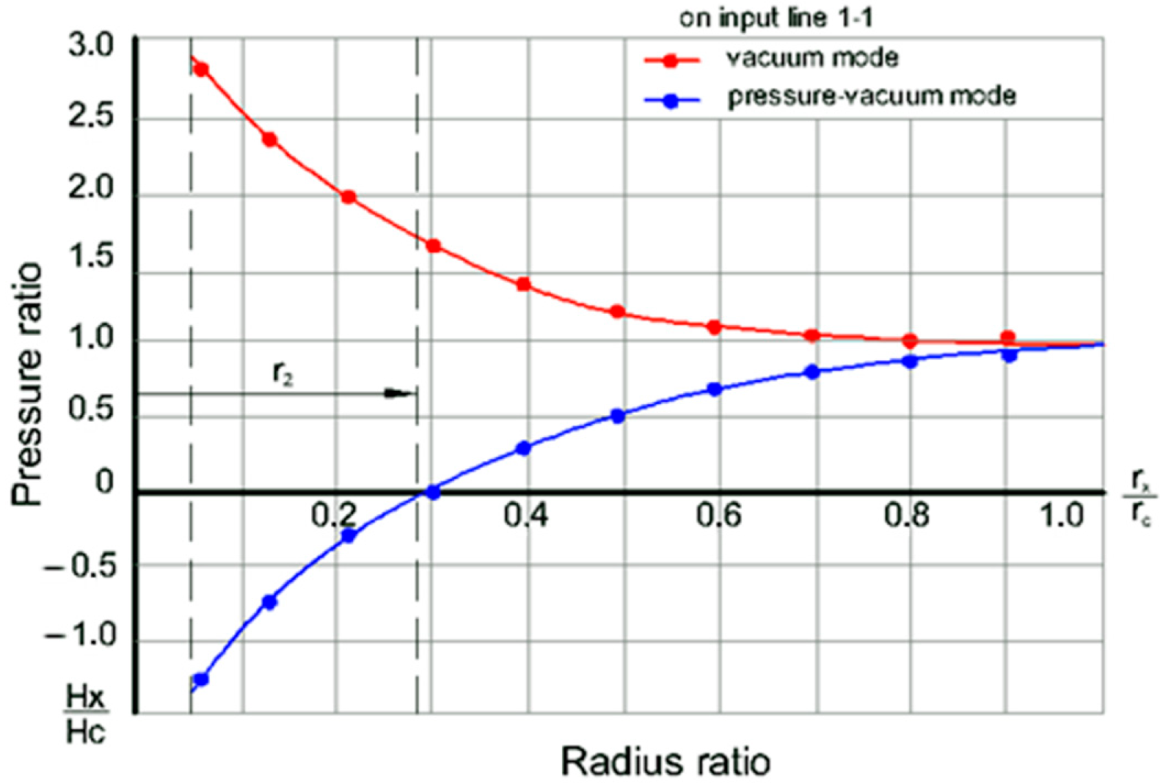
a. The given conditions for the transition from one regime to another are clearly seen from the profiles obtained during the experiments (
Figure 2).
As can be seen from the figure, at a pressure at the inlet to the hydrocyclone within P
1 = 0–5 kPa, a vacuum field is completely established inside the hydrocyclone apparatus, which has a minimum value in the near-wall zone. A more significant deepening of the vacuum in the area of the drain pipe provides an intensive flow of liquid into the suction pipe of the pump. The pressure profiles of the flow in the pressure-vacuum mode of operation of the hydrocyclone present a somewhat different picture. In this case, when P
1 = 10–15 kPa, the vacuum field is observed only in the central part of the hydrocyclone, and the peripheral zone in height is in overpressure. In this case, the generalized curve for all can be described by the following empirical relationship (
Figure 2). With a decrease in the flow rotation radius, the value of excess pressure decreases, and at the point of intersection with the line of the radial section it is equal to zero, i.e., the absolute value of liquid pressures is equal to the atmospheric pressure P
a = P
atm. In both cases, in the center of the hydrocyclone flow along the apparatus, a space is formed that is not filled with liquid (an air column). In this case, the generalized curve for all sections can be described by the following empirical relationship (
Figure 2):
H, where is the head on the considered hydrocyclone section radii, m; are the radii of the hydrocyclone and in the studied sections, m.
As can be seen from
Figure 3, the set of flow turbulence settings provides correct modeling of the required process, which confirms the obtained pressure distribution isolines at the beginning of the transition to the pressure-vacuum mode in the hydrocyclone.
In this case, the calculation was carried out using the SolidWorks program (Flow Simulation module) for the numerical simulation of gas and liquid flows. Turbulence was calculated from the modulus of turbulence (k–e). The grid adaptation tab was selected at level 2, and the maximum number of cells allowed was 8,200,000.
It also follows from these studies that the beginning of the free removal of liquid from the sand hole corresponds to the ratio , and at pressures , the vacuum field is preserved at the sand hole. At the end point of the working zone, the residual pressure was relatively high, which allowed for additional thickening of the pulp and its removal from the hydrocyclone to the outside. It has been established that the flow rate through the sand hole increases with an increase in the relative pressure of the ejector.
3.2. Redistribution of Water Flow in the Hydrocyclone between Discharge Openings
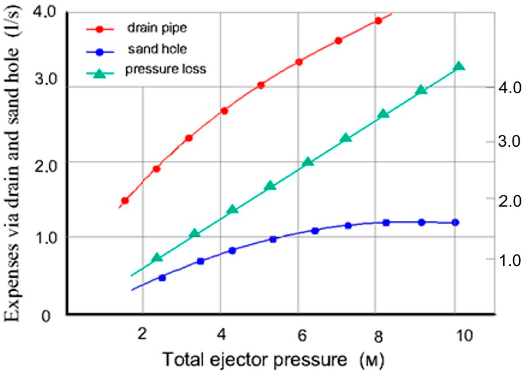
The peculiarities of water flow redistribution become noticeable when the ejector head He exceeds the cantilever pump inlet head Hp by one order of magnitude or, at least, when they are equal to each other, which ensures hydrocyclone operation in the under-pressure conditions. The pressure loss in the hydrocyclone is Δh = 15–30 кPa.
(
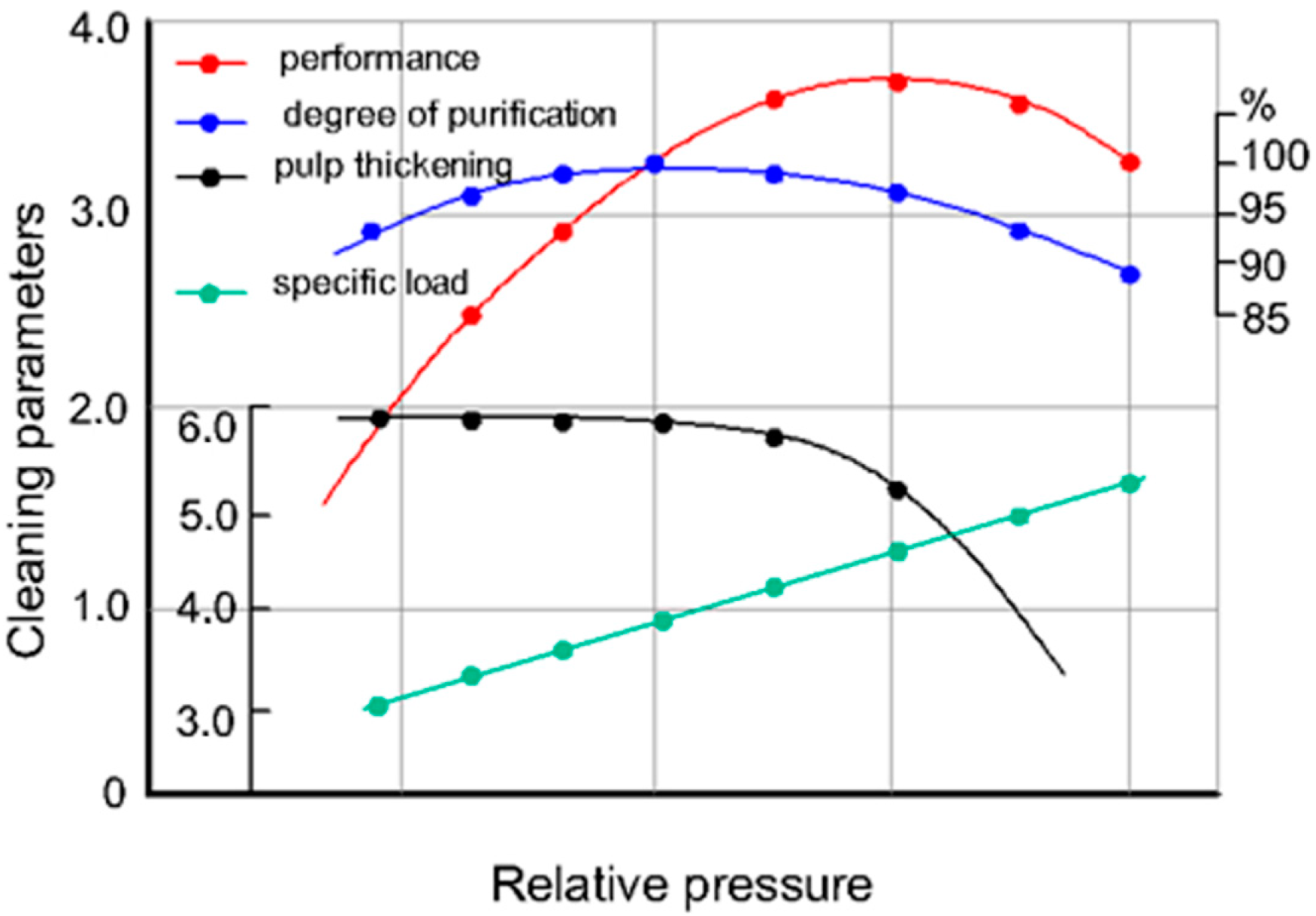
Figure 4). It is characteristic that in the thickening mode, when the pressure at the hydrocyclone inlet exceeds P
1 = P
e = 55–60 кPa, the relative thickening index decreases to Ko = 2.8–3.0 and thus the water losses increase by 10–15%. This shows the inefficiency of the unit in the full pressure mode.
Water losses are reduced to the lowest value, Δw = 2.5–3.0%, when creating the pressure-vacuum mode (P
1 = 40–50 кPa), although the specific load on the sand hole does not exceed the allowable value (q
3 =1.9 t/h cm
2), adopted for the size of the sand hole (d
3 = 20–25 mm) (
Figure 5).
The hydrocyclone plant operation under vacuum conditions was not considered due to the lack of necessity for the investigated scheme of the water-pool lift and catchment well design simplification.
The high relative thickening (Ko = 5.10–5.84) of slurry with the lowest water losses through the sand hole was supposed to be achieved during the hydrocyclone operation with the formation of sand accumulation at the sand hole outlet.
Experimental data obtained in the indicated mode on the solid phase distribution between the discharge openings of the apparatus are shown in
Table 2.
It follows from the above material that the sand accumulation to a height of up to 1/3 of the hydrocyclone length does not reduce the base pump flow rate (Qp = 4.48–4.87 L/s) and the water purification degree with mechanical impurities (Ee = 93–96%). The water consistency passing through the drain pipe does not exceed K2 = 0.008, and no particles with diameters larger than 0.04–0.05 mm pass through, which helps to protect the pump impeller from abrasive wear.
This means that purified water can be reused for the next cycle of ejector water supply without purification and the use of additional settling tanks, unlike most of the existing ejector installations [
1,
5,
46]. Due to this, savings in construction costs and rational lifting of water with solid particles are achieved.
It turned out that it was necessary to ensure the optimal value of the specific load on the sand hole (q3 = 1.5–1.6 t/h per 1 cm2) by adjusting the outlet cross section using a throttling device, mainly automatic, in order to maintain the indicated rational mode. Reduction in the unit productivity from the ground up to Q3 = 0 occurs at hydrocyclone overloading by the thickened mass, as the drain hole fully overlapping does not allow the realization of free removal to the dump. There is a violation in the redistribution of the solid phase and a decrease in water purification systems by 30–40%. The redistributive nature is also affected by a change in the ratio of the sand and drain holes’ sizes. Reducing this ratio increases the proportion of granular grains carried away toward the base pump suction.
Tests have shown that the density of treated (rendered) slurry was p
3 = 2.13–2.21 t/m
3, and water losses were equal to Δw = 3.84% at relative thickening of slurry in the range.
3.3. Hydrocyclone–Ejector Technology Efficiency Parameters Establishment and Economical Mode of Joint Operation
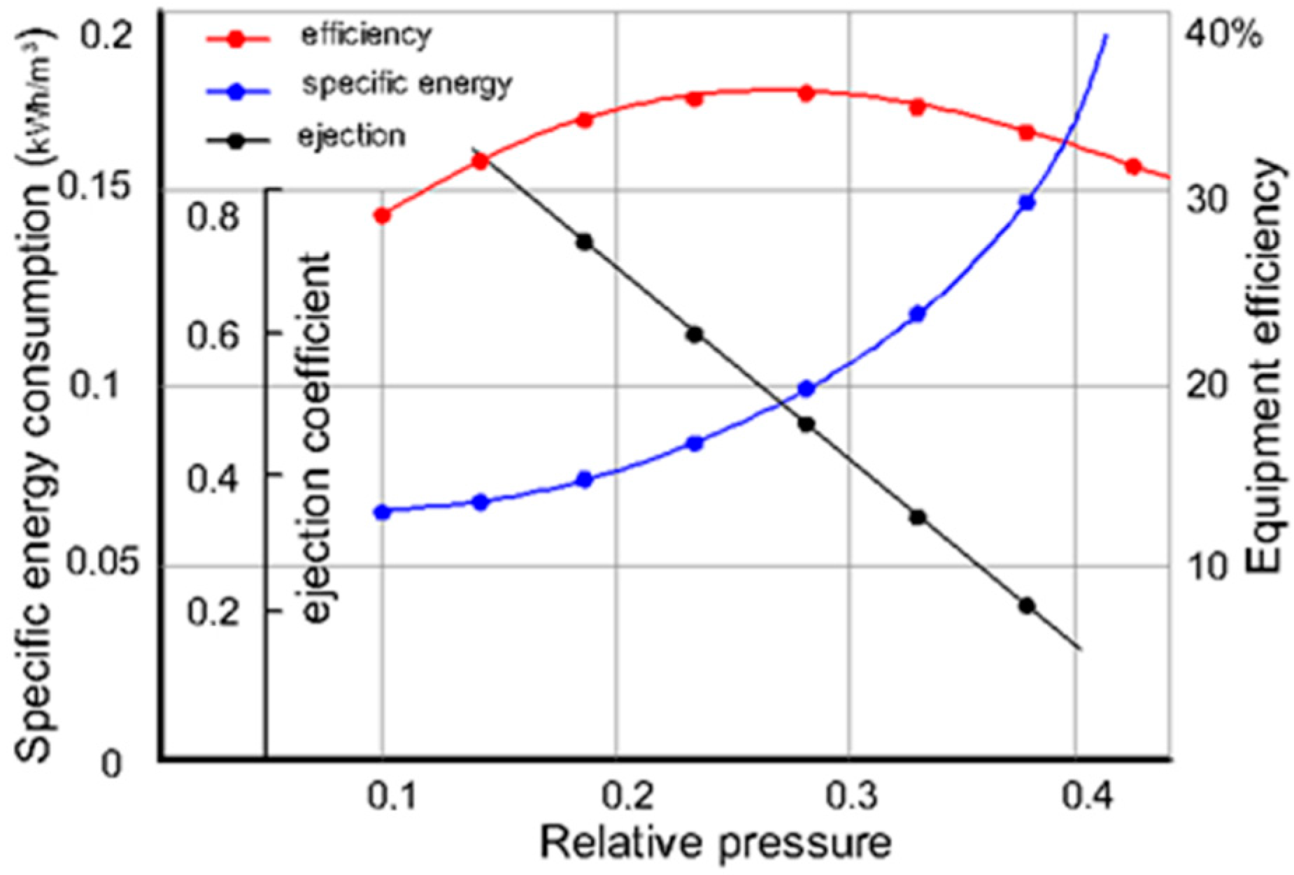
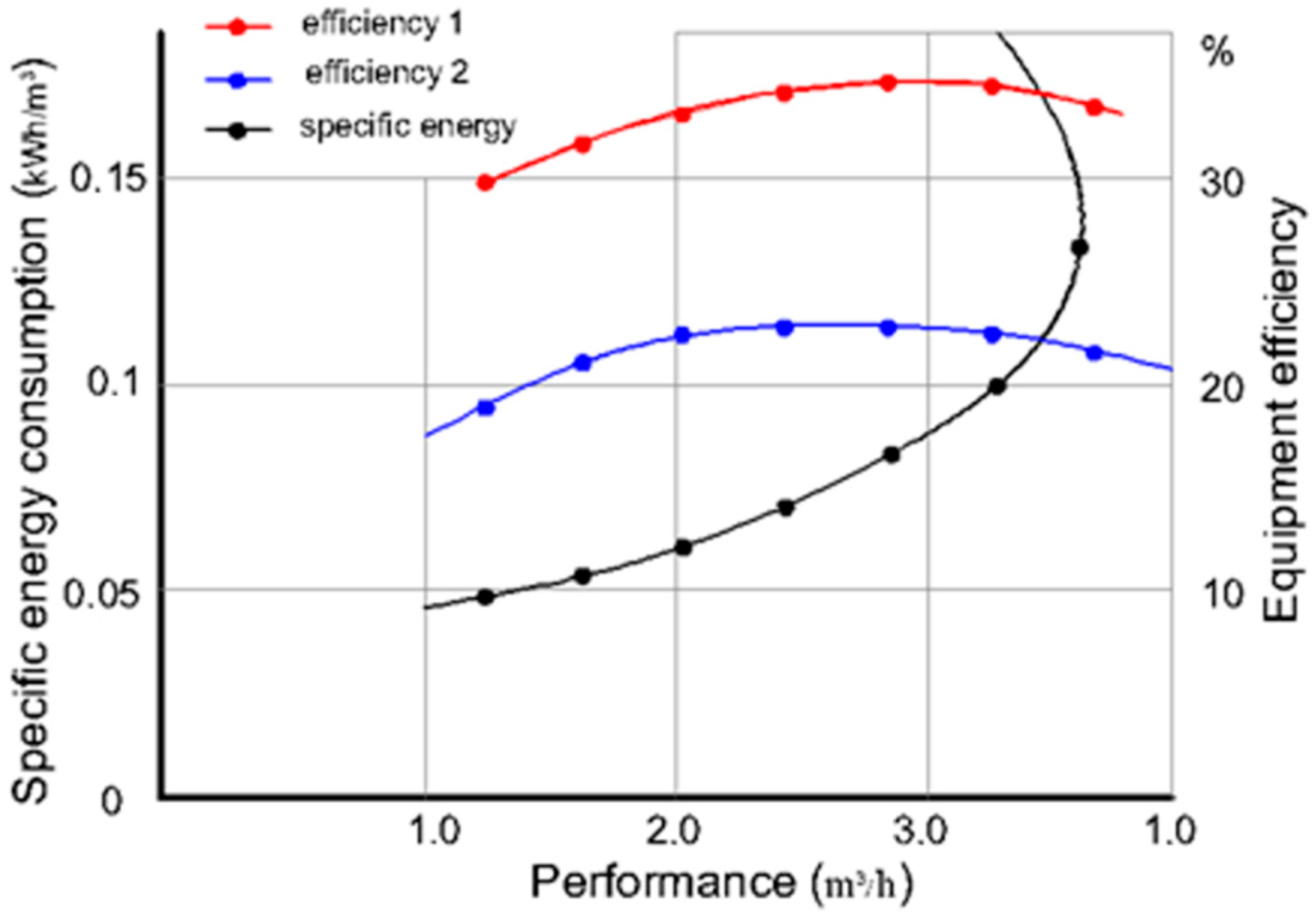
The obtained test results are presented in
Figure 6 and
Figure 7, in the form of graphical dependencies
,
и
,
,
.
It is established that at joint operation with a centrifugal pump, the mode coefficient of efficiency, taking into account the manufacturability of the adopted closed circuit, varies within and the dependence-change general pattern, , is preserved. The values of ejection coefficients can be increased by up to 0.815–0.875 by increasing the plant suction capacity.
A sharp jump in the value of energy consumption per 1 m3 of thickened mass is observed when the relative head increases to he = 0.4 or more, if the specific energy consumption in the working zone (he = 0.250–0.310) varies within acceptable limits. This is due to compaction of the processed sand mass in the hydrocyclone conical part and overloading of the hydrocyclone unit due to operating mode violations
The ejector’s relative pressure must therefore be taken as equal to its critical value during the operation of hydrocyclone water-lifting installations with the hydrocyclone method of cleaning and thickening. This circumstance is also confirmed in the analysis of specific energy costs depending on the productivity of the hydrocyclone on the ground . The plant-given energy efficiency does not exceed the base value (ηe = 0.233–0.245), which was obtained when using an ejector to lift water from a well.
It turns out that a change in the ejector’s backwater leads to a decrease in its suction capacity, and an increase in the diameter of the discharge hole increases the flow rate of the ejected stream, and consequently, the hydrocyclone productivity. It is also a characteristic that the function reaches a minimum in all discharge hole ratios at the beginning of the transition of the hydrocyclone chamber from vacuum to pressure mode.
4. Conclusions
The features of the change in the characteristics of the ejector water intake and treatment plant, revealed in the course of the study, depending on the ratio of the vacuum at the inlet to the centrifugal pump and the pressure of the ejector under the conditions under consideration, make it possible to control the operation of the installation when cleaning the raised water. At the same time, the advantages of both pressure (free mass of thickened mass) and vacuum (protection of the pump from abrasion) hydrocyclones are combined.
The established ratios of the vacuum suction head of the pump and the head at the inlet, corresponding to the boundary conditions for the formation of vacuums, pressure-vacuums, and pressure modes of fluid movement in one hydrocyclone, allow one to use the same hydrocyclone apparatus in various technological schemes of water treatment as needed.
At P1 = 10–15 kPa, the vacuum field is observed only in the central part of the hydrocyclone, and the peripheral zone in height is in overpressure.
The rational technological parameters of the improved design are characterized by the water capacity of the ejector in the range Qe = 4.2–4.7 L/s and the degree of purification up to 96% in the hydrocyclone.
The optimal value of the specific load on the sandbox (q3 = 1.5–1.6 t/h per 1 cm2) must be ensured to maintain the required mode by adjusting the cross section of the outlet with an automatic control valve. When overloading the conical part of the hydrocyclone with sand, the redistribution of the solid phase is violated, and the water purification is reduced by 30–40%. The change in the ratio of the dimensions of the discharge nozzles also affects the nature of the redistribution. It has been established that the relative pressure of the ejector must be taken as equal to its subcritical value when working together with a hydrocyclone.

