Abstract
Volume reduction has been suggested as a novel method to tackle the various challenges associated with produced water. The present solution offers an economical and environmentally friendly solution to treat a large bulk of produced water that may overwhelm conventional water treatment methods. The current study provides a review of the various volume reduction technologies including freeze concentration, reverse osmosis, and humidification and dehumidification desalination systems. Focus is concentrated on the general HDH technologies in addition to its integration with refrigeration cycles for conditioned air production, and the power cycles for power generation. The GOR, freshwater yield, and efficiencies of the integrated HDH systems were reviewed. Lastly, innovation in the HDH desalination technology is discussed with emphasis on its incorporation with the MVC process.
1. Introduction
While an increase in energy demands especially from the oil and gas sectors present several challenges, one of the prominent problems faced is that of produced water (PW) [1]. PW is water associated with the extraction of oil and gas and is considered to be one of the largest contributors of generated wastewater. Reports have indicated that nearly 21.2 billion barrels of produced water were generated in 2012, in the United States alone [2]. The bulk of the waste stream in offshore oil and gas operation is PW, accounting for nearly 80% of the waste produced. Moreover, the amount of PW is observed to increase as the age of the oil wells increase [3]. McCabe [4], through his studies, has reported that the volumes of PW in exhausted fields can reach up to 98% while producing only 2% of fuel. While the current oil extraction trends provide a 3:1 water to oil produced ratio, the production of PW is expected to increase as the wells age [4,5]. It has been estimated by Burnett [6] that the ratio of water to oil could reach up to a ratio of 10:1 as the well matures. With such large volumes of PW generated, optimal treatment and reuse is paramount. On the other hand, water scarcity continues to become a global concern affecting nearly 2 billion people, and the situation is expected to worsen with further industrialization and urbanization [7]. While freshwater production from natural resources may not be a viable option for many regions, desalination of saline water and opportunities to reuse PW as a means to reduce water stress may be a valuable resource. Optimizing the reuse of PW in the oil and gas industries is not limited to enhanced oil recovery but is also relevant for well drilling and hydraulic fracturing procedures. PW reuse minimizes underground disposal volume, surface discharged volume and all associated costs. While there is reported reuse of PW in the oil and gas industries, PW can also be employed for livestock watering, irrigation, and stream augmentation; however, less than one percent of the generated PW is used for such applications. Promotion of the wider reuse of PW may be more applicable with further research and development of cost effective and ecofriendly technologies.
The present paper highlights the potential for desalination techniques to meet freshwater requirements through various volume reduction techniques while placing emphasis on the humidification–dehumidification (HDH) desalination system. The prime advantages offered by the HDH process lie in the simplicity of its design and low capital cost. In addition, the process is adequately flexible to be integrated with other technologies, requires low maintenance, utilizes low-grade energy, and can be applied in decentralized areas [8]. The undeniable advantages provided by the HDH technology have prompted researchers to further their existing knowledge on the system by integrating it with various refrigeration, power, and desalination cycles to increase productivity while optimizing energy consumption.
2. Produced Water Treatment
With more than 21.2 billion barrels of PW being generated each year, it is essential to treat and reuse this water; however, what makes PW treatment and reuse challenging, apart from the large volume, is its complex and non-uniform mixture. The composition of PW can vary in total dissolved solid concentration, organic content, and metal concentration depending on the place and position it was generated. The possible presence of heavy metals further exacerbates treatment operations by causing corrosion of and scaling on equipment. Despite the obvious challenges, several studies each exploring the efficiency of repurposing PW have been conducted. Ahmadizadeh [1] conducted the studies on the efficiency of halophilic microorganisms and forward osmosis (FO) to reduce the volume of PW and present organic pollutants. They concluded that the FO process was capable of reducing the volume of PW by 30% while a subsequent Osmosis Membrane Bio Reactor could extract 66% of the organic matter. Visvanathan [9] suggested the use of reverse osmosis (RO) for the volume reduction of PW, provided that an appropriate pretreatment was selected. Adsorption as a treatment method was studied by Janks [10] using tailored zeolites. The Crudersorb technology that employed a series of adsorption steps was reported to reduce oil and grease content to less than 29 ppm [11]. Although frequently applied for particle extraction from water samples, the prominent drawback of the adsorption methods is the frequent regeneration of adsorbents and the waste generated. Adewumi [11] suggested the use of sand filtering preceded by a set of pretreatments for the efficient removal of metals from PW. While separators such as centrifuges and hydro-cyclones were industrially used for de-oiling PW, Van den Broek [12] hinted towards the low performance efficiency of the systems, also commenting on the inability of the methods to extract hazardous components, thus requiring other post treatment options. Other physical PW treatment methods such as evaporation, C-TOUR, dissolved air precipitation (DAP), freeze concentration, and electrodialysis are available but are either patented designs or were inadequately researched and applied.
Chemical treatment of PW in contrast to many physical treatment methods is less time-intensive and could be tailored for more efficient extraction of pollutants. Among the several materials available for chemical precipitation, FMA, a polynuclear polymer, displays appreciative coagulation, and could de-oil PW with an efficiency greater than 92% [13]. Studies conducted by Houcine [14] for the removal of heavy metals displayed a removal efficiency of more than 95% when lime was used. The method of chemical oxidation to reduce both the organic and inorganic compounds from PW through the application of oxidants and catalysts have been extensively used in several industries. Commonly used oxidants such as H2O2, O3, K2FeO4, etc., are capable of reducing complex organic pollutants to smaller, more manageable forms. These oxidants fall under the category of an advanced oxidation process [15], a technology that relies on the production of hydroxyl radicals for the required oxidation. Despite the impressive effectiveness of the Fenton chemical oxidation process, Ganiyu [16] and Zhang [17] remark that the precipitation of the iron ions severely impacts the efficiency of the process and produces undesired sludge. Hydrophobic ionic liquids, with their versality, were observed to display an affinity for extracting organic pollutants from water [18]; however, their application for commercial use is restricted due to the limited technology required and lack of suitable post-treatment options available.
While reliable and effective, chemical treatment of wastewater and PW often uses toxic chemicals that presents secondary pollution problems. In addition, chemical treatment methods thus far discussed are cost intensive. In response to the afore-mentioned challenges, alternative treatment methods in the form of membrane treatment were researched and applied. Microfiltration (MF) [13], ultrafiltration (UF) [9], nanofiltration (NF) [9], and reverse osmosis (RO) are predominantly used in the water treatment industry. The application of the methods depends on the size of the pollutants to be extracted. Typically, MF is applied to remove suspended solids, while UF is used for the separation of macromolecules. The RO method is capable of separating dissolved solids and ionic compounds and NF is primarily applied for the extraction of multivalent ions [19]. Ciarapica [20] stated that membrane systems are capable of treating water high in oil content and can thus be suitably applied in offshore platforms. Figure 1 summarizes the various PW treatment technologies available for commercial application.
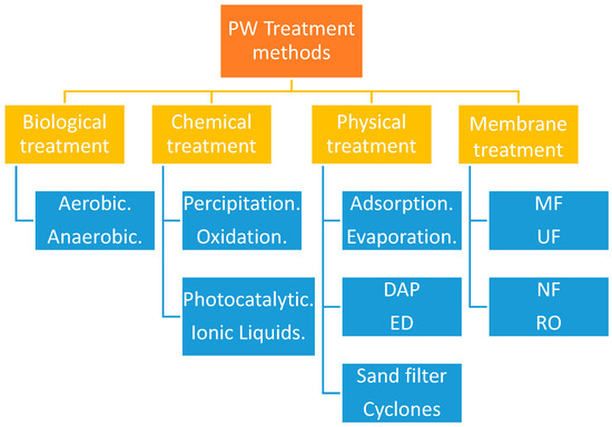
Figure 1.
PW treatment methods.
Although physical treatment, chemical treatment and membrane treatment technologies thus far discussed have proven to be effective for wastewater treatment, the shear bulk of PW generated often overwhelms the technologies and is associated with high treatment costs. To counter this, volume reduction is sought as a more economical and environmentally friendly alternative. Recent studies have highlighted the use of reverse osmosis (RO), freeze concentration (FC) and evaporation as a means to achieve a volume reduction of water with the aim of obtaining clean water. The present study aims to summarize each of the volume reduction technologies for concise comprehension and comparison.
3. Freeze Concentration
Freeze concentration (FC) focuses on extracting water from a solution, through crystallization. This translates to freezing water into ice crystals of high purity while organic and inorganic pollutants are concentrated into the remainder of the solution. The crystallization process is a subject of interest in many industries, particularly in wastewater management for its numerous advantages. The closed system is capable of handling solutions of varying compositions while preventing the loss of volatile compounds to the surrounding environment. The low temperatures of the process further prevent the corrosion of equipment used [21]. The overall capital cost of the process is lowered as inexpensive materials for construction can be employed because of the low operating temperature of the system. More importantly, the process is highly energy efficient compared to thermal desalination alternatives. This is attributed to the low latent heat of freezing as compared to the latent heat of evaporation [22].
Although interest in FC can be traced back to 1786, the method has remained a subject of little practical application and was thought suitable only in regions of colder temperatures. The innovation of refrigeration machines revived a short-lived interest in the process and the availability of surplus energy bought forward by the crude oil industry in the 1970s shifted interest in the use of alternative water purification methods such as RO and evaporation. In more recent times, the application of FC, though limited to the food industry, has been regaining attention for more commercial applications. Figure 2 is used to depict a typical FC process flow.
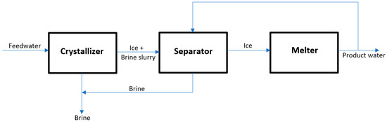
Figure 2.
Schematics of the freeze concentration process.
The FC method is subdivided into a suspension freeze concentration (SFC), progressive freeze concentration (PFC), and block freeze concentration (BFC). The prime difference between these methods is the size of the ice formed and the equipment used to achieve it. The SFC method involves the use of an array of equipment, such as heat exchangers, recrystallization drums, and washing towers to produce small ice crystals. The use of the large amount of equipment translates to higher operating costs of the method. For this reason, continuous research and development is carried out to optimize the method. The PFC method, in contrast, relies on the formation of a single large ice crystal with the use of minimal equipment. The crystals are designed to be formed on the cooling surface thus allowing for easier separation between the crystals and the solution. Although the PFC involves a simple operation, low cost, and high purity of crystals, the productivity is low when compared against the SFC method. Moreover, the volume of crystals produced are also low [23]. BFC is a two-step process, that first involves the freezing and thawing of the solution to recover a highly concentrated potion of pure ice, followed by gravitational separation techniques.
Despite promising potential, only a few studies have been conducted on the application of the FC technology as a means of volume reduction of PW. Samsuri [21] evaluated the efficiency of PFC for extracting water from PW and biodiesel water. The efficiency of the system was evaluated through the effective partition constant (K) and the separation efficiency [24]. The effective partition constant (K) is defined as the ratio of solute concentration in the crystals to that in the liquid phase. This factor is represented in Equation (1). The separation efficiency [24] can be used equally well to define the system efficiency and is defined is Equation (2).
where CS represents the solute concentration in the crystals. CL is the solute concentration in the liquid solution.
where CO is the initial concentration of the solution. Higher values of SE translate to higher efficiency of the system while lower K values indicate improved efficiency.
While testing the effect of stirring on the water removal efficiency of the PFC process, it was observed that the K constant decreased as the stirring rate was increased. They concluded that the rate of stirring decreases the advance rate in the ice front [21]. The vigorous movement of the solution bought forward by stirring will cause a decline in a slower solidification rate, thereby resulting in lower amounts of solutes concentrated in ice. Verifiable results were obtained by Halde [25] who further explained that aggressive stirring prevents solute build-up at the interface; however, care should be taken as excessive stirring can erode the ice crystals formed.
The dependency of the PFC method on the temperature was then evaluated. The observed trend was non-linear with the highest efficiency achieved at intermediate temperatures of 16–18 °C. It was justified that at such a suitable temperature, the theoretical velocity of mass diffusion supersedes the speed of heat removal, thus allowing for the diffusion of the solutes and escape from the freezing point [25].
Latent heat is released into the coolant and solution as the crystals proceed to grow. Therefore, lower coolant temperatures are justified to maintain a constant solution temperature; however, too low a coolant temperature can yield unsatisfactory results. This is because at such low temperatures the structure of ice is fragile and dendritic, thereby trapping solute particles in it.
Williams [26] studied the application of FC for desalination and reviewed the four categories of the freezing process generally applied in industries. This includes direct contract freezing, vacuum freezing and indirect contact freezing.
In direct contact freezing, a liquid hydrocarbon immiscible with water is used as the refrigerant and bought into direct contact with seawater. Initially the refrigerant is under high pressure. Upon expansion, the refrigerant evaporates, cooling the seawater and forming ice. The hydrocarbon vapors are then compressed and recycled to the process while its heat is used to melt the obtained ice. This method provides the benefits of a high production rate per unit volume and low power consumption; however, since the refrigerant used is in contact with the water, there is a high possibility of retention of the hydrocarbon in the ice. Thus, further treatment is called for to make the water potable.
In the vacuum freezing method simultaneous evaporation and freezing occurs. The refrigeration effect is bought forward by water which is vaporized by the high vacuum employed. This causes the brine temperature to significantly drop and form ice. Theoretically, it is estimated that 1 kg of water evaporated could yield 7 kg of ice. This was based on the calculation that the latent heat of vaporization is seven times greater than the latent heat of freezing [22]. Therefore, the system is associated with high production efficiency. By eliminating the use of other chemical refrigerants, contamination and separation problems are averted, but the application of the method is severely hindered by the complex compressor design required to process the large specific volume of water vapor [26].
To counter this Lu [27] suggested the hybridization of vacuum freezing. They recommended the vacuum-freezing vapor adsorption (VFVA) system and the vacuum-freezing high-pressure ice melting (VFHPIM) process. The VFVA involves the adsorption of water vapors followed by its reclamation from the adsorbent. By replacing the compressor with an adsorption system, energy is supplied to the system by the latent heat of steam in the absorbent generator [27]. In contrast, the VFHPIM method employs neither a compressor nor an absorbing solution for the low-pressure water vapor. These processes are efficient and cost competitive alternatives to conventional desalination processes.
In the indirect contact freezing process, as the name suggests, the refrigerant is kept away from seawater in a conventional vapor compression refrigeration cycle. This cycle first absorbs heat from the seawater and then transfers it to the melting unit where ice crystals are present. In a sense, the freezer chamber and the melting unit represent the evaporator and the condenser of the refrigeration cycle, respectively, thereby optimizing the process to a degree. Despite this, further optimization of the compressor is required. This is to ensure that the refrigerant temperature is well below that required by the freezing chamber and higher than that of the melting chamber [26]. Although straightforward in its operation, indirect contact freezing is associated with high energy consumption. Weiss [28] explains this is primarily due to the resistance to heat transfer between the refrigerant and seawater. Rahman [29] further elaborated that large metallic heat transfer surfaces would be required for efficient operation of the freezing chamber and the melting unit. Thus, more complex equipment design is required and at a higher capital cost. The drawbacks of the method far outweigh the benefits provided by it rendering the process infeasible for large scale commercial application.
Several papers have been dedicated to highlighting the advantages offered by freeze concentration in various commercial fields, primarily for desalination and water treatment. While the FC process has lower energy consumption as compared to other desalination processes and prevents the problems associated with equipment corrosion, its commercial application is limited. Rahman [30] explains that the large separation energy costs for the development of FC technology presents severe challenges to its industrial application. To overcome this, further energy and economic analysis of the method should be conducted while also considering integration of the process with existing commercial processes.
4. Reverse Osmosis
PW is a source of many organic and inorganic pollutants, metals, and other contaminants; however, the major source of contaminants is the TDS. The presence of large amounts of TDS has promoted the use of reverse osmosis (RO) for PW treatment as a novel volume reduction technique. Visvanathan [9] claims that although RO is sensitive to fouling due to the presence of organic matter, the use of appropriate pre-treatment methods can help overcome the problem. Tao [31] suggested increasing the pH of PW before treating in the RO unit to prevent fouling. By controlling the pH of the solution, the solubility of oil can be increased thus reducing RO membrane fouling; however, care must be taken, as increasing the pH to higher levels may lead to membrane scaling. Despite the obvious drawbacks, RO technology has been used for water treatment at an industrial scale because of its lower carbon footprint and energy cost. Furthermore, RO does not require the use of chemicals and, therefore, post treatment methods if required are simplified. Figure 3 describes the simple schematics of a RO process.
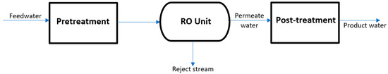
Figure 3.
Reverse Osmosis process flow.
Visvanathan [9] conducted studies of several pre-treatment methods on a pilot-scale plant to select the technique most suitable for the RO process. Among the selected pre-treatment methods were microfiltration [13], ultrafiltration [9], and nanofiltration [9]. Multimedia gravity filtration was used prior to all pre-treatment methods to remove larger pollutants that could impede the process.
The experimental runs for the microfiltration employed 20 µm and 1 µm filter bags. A significant decline in RO flux was observed soon after operation. Moreover, microfiltration was unable to remove oil contents completely from the feed water. Membrane autopsies indicated irreversible fouling of the membranes used. In response to the failure of microfiltration as a pre-treatment method, the potential of ultrafiltration was tested. Two types of membranes were tested: a hollow fiber UF membrane and a spiral wound UF membrane. While the spiral wound membrane provided oil rejection of up to 85%, and the hollow fiber membrane rejected oil content up to 40%, there was a noticeable RO flux decline in both cases [32]. Irreversible membrane fouling occurred for both membrane types used after a few days of operation. It was concluded that fouling of the membranes was not only attributed to the presence of oil molecules but also other organic matter present in the water. Although the UF membrane performed better than the MF membranes, it was unable to extract low-molecular weight organic matter. Therefore, the performance of nanofiltration was tested for further comparison. Among the many NF membranes tested, polypiperazine-based membranes performed well especially with regards to fouling. The NF 45 membrane was also reported to be adequately resistant to fouling. Furthermore, the fouling was reversible in nature. Thus, Visvanathan [9] recommend RO treatment paired with NF and gravitational filtration as a pre-treatment for the volume reduction of PW. Their suggestion was further verified by the positive results obtained from the pilot-scale NF + RO plant treating PW. It was reported that the system could process irregularities in PW composition without any significant impact on the filtration efficiency and only periodic cleaning of the membrane was required.
Mondal [33] investigated the use of polymeric membrane nanofiltration and low-pressure, RO thin film composite (TFC) membranes for PW treatment. Among the different types of membranes tested, the NF 270 membrane provided the least reduction in flux, while the BW 30 membrane yielded the highest purity of permeate. It was concluded that for practical applications, the choice of membrane largely impacts the water quality, and that membrane filtration can be optimized to become a feasible PW treatment method.
McGinnis [34] and Chen [35] proposed the use of forward osmosis [1] as a means of volume reduction. They claimed that since PW is often characterized by high salinity it can thus be used as a draw solution (DS). Moreover, employing FO for PW treatment can offer high water recovery and reversibility in fouling. McGovern [36] counters the claim by highlighting the high energy consumption required for the regeneration of diluted draw solution post the FO process. Several studies have since then been dedicated to minimizing the drawbacks of the FO process while optimizing the advantages offered by it. The most noticeable suggestion was the combination of two driving forces to attain high water recovery and energy efficiency [37,38]. This operating process was named osmotic assisted reverse osmosis (OARO) or osmotically enhanced dewatering [39] wherein the DS of a lower concentration than the feed solution [13] is used to replace a part of the hydraulic pressure as osmotic pressure [39]. Thus, OED can operate at hydraulic pressures lower than that required by a RO system resulting in increased energy efficiency and water recovery. Through their investigation on the effectiveness on OED on shale gas PW, Kim [38] concluded that the OED process offers improved water recovery, lower concentration of the diluted solution and greater reduction on the membrane area requirements as compared to the FO system. They attribute the effectiveness of the OED to the enhanced water transport through the membrane without the impact of the internal concentration polarization seen in the FO process. Lastly, the OED process displayed satisfactory rejection of most ions with feed water recovery reaching up to 67%. This indicated the potential of the OED process for PW treatment; however, further economic evaluation and development of suitable membranes are suggested.
Recent studies have seen the application of membranes for air humidification as well as humidification–dehumidification desalination. Several membranes have been evaluated for their application. In their studies, Zhang et al. [40] showed that hollow fiber membranes offered significant advantages for air humidification over other conventional technologies. This was especially true when the mentioned membranes were coupled with counter flow heat and mass transfer. In membrane-based air humidification processes, moisture droplets are prevented from mixing with air while the membranes effectively allow for water to pass through them. A similar study conducted by Li et al. [41] tested hollow fiber membranes for humidification–dehumidification desalination. They studied the effect of membrane thickness, heat conductivity, membrane area and moisture diffusivity on the performance of the membranes and validated it against experimental data. It was concluded that moisture diffusivity and membrane area were the prime parameters that effected performance. Zhang et al. [42] conducted studies on composite hydrophobized membranes on polyvinylidene supports. The developed membranes displayed exceptional antifouling properties without compromising the permeability. While currently limited, studies are available for membrane application for air humidification and interest in the field is significantly growing.
5. Humidification and Dehumidification Desalination
Humidification–dehumidification desalination (HDH) is described as a novel volume reduction method that employs a carrier gas for the thermal desalination of water. Currently used for small scale desalination, the advantages provided by the HDH method are too great to be ignored. The benefits of the process include the use of low-grade energy and simple design and construction.
A simple HDH system primarily consists of a humidifier and a dehumidifier and its working principle is inspired by the natural rain cycle. To elaborate, the HDH relies on the ability of air to absorb and carry moisture from a water source. In this manner, in the humidifier saline water is brought in contact with air. The concentration gradient of water vapor between the air and water interface causes the diffusion of moisture into the air. The dehumidifier is then employed to collect freshwater from the air by means of condensation. The HDH system also requires the use of a heating medium. This then helps classify the system as water heated (WH) [43] or air heated (AH) [44] depending on the type of heating used for each stream. The heating medium plays a crucial role in the system as their thermal energy determines the amount of the pure water to be vaporized from the saline water. Generally, the capacity of the medium to vaporize freshwater increases with a rise in its temperature [45]. Figure 4 presents the schematics of a simple HDH cycle.
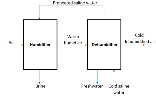
Figure 4.
Schematic of a simple HDH desalination system.
Kabeel [44] suggested the use of saline water as the cooling medium in the dehumidifier. Doing so aided in the recovery of the latent heat from the warm humid air, and so helped pre-heat the saline water to be fed to the HDH system. Despite the simple design of the process, several studies have been dedicated to providing variation in the components with the aim of further optimizing the process. El-Dessouky [46] suggested the use of waste heat from a gas turbine power plant for the HDH system while Al-Hallaj [47] studied the performance of a solar desalination unit using the HDH system.
While the performance of the HDH cycle can be represented in terms of yield, and cost of freshwater, the most common index of performance is the GOR. The gained output ratio (GOR) is defined as the ratio of the total latent heat of evaporation of freshwater produced to the energy provided to the HDH system. The GOR is calculated using the following equation:
where, refers to the flowrate of freshwater produced, is the latent heat of evaporation of freshwater, and is the energy input to the HDH process.
Higher GOR values indicate better performance of the HDH system.
Studies were also dedicated to analyzing the HDH configurations for maximum efficiency and productivity. The three main configurations of the HDH are, namely, the closed-air open-water (CAOW) cycle, the open-air open-water (OAOW) cycle, and the open-air closed-water (OACW) cycle.
Narayan [48] and Mistry [49] aimed to discuss methods for the optimization of the HDH process by investigating its thermodyanmic behaviour using the first and second law of thermodynamics. Their studies, however, were limited to the optimization of the process to a single parameter. On the contrary, Mistry [50] claimed that HDH cycles are functions of various parameters, therefore more methodical optimzation calculations are required.
In their paper, Mistry [50] aimed to determine the operating conditions and configuration best suited to provide optimal results in terms of the GOR. They claimed that when using the WH cycles, OAOW configuration exhibited better performance when compared to the CAOW configurations, regardless of the relative humidity. In a similar fashion, within the AH cycles, CAOW configuration yielded better results than OAOW cycles with the exception of a condition of 100% relative humidity. While it was observed that both the WH and AH cycles provided comparable GOR, the AH cycles often required the use of larger humidifiers and dehumidifiers than the WH cycles [51].
Several studies then integrated the HDH desalination process with other conventional methods with the aim of achieving a higher GOR value and therefore an improved performance of the system. Narayan [48] reported a GOR of greater than five for a multistage HDH system paired with thermal vapor compression (VC) cycles. Narayan [52] proposed increasing the efficiency of the HDH system through integration with a RO unit. They reported that the combination could yield a GOR of up to 20, which is significantly higher than that obtained by conventional HDH systems. The effect of pressure on the GOR was investigated by Siddiqui [53]. It was reported that a maximum GOR of 8.2 was achieved when the humidifier was operated at a pressure of 50 kPa.
Heat pumps as a source of energy to be used in desalination systems has been garnering great attention over the recent years. The use of a solar assisted heat pump was studied by Hawlader [54] using a single effect evaporation desalination unit. Studies conducted by Gude and Nirmalakhandan [55] combined solar assisted air conditioning systems with desalination. The effectiveness of the adopted system yielded results in close competition to the multi-stage flash distillation (MSF) process with a desalination efficiency of 80–90%.
Lawal [56] presented two layouts of HDH with heat pumps aiming to improve the performance and the GOR of the HDH system. Through their experiments, the influence of the mass flowrate ratio (MR) on the GOR of the system was observed. It was noted that increasing the MR coincided with an increase in GOR until an optimum value before a decrease in the GOR with an increasing MR. They explain that high values of MR may cause flooding in the HDH system with insufficient air supply in the humidifier. Therefore resulting in a decreased GOR. The peak value of the GOR is attained when the humidifier has an optimum flowrate of air and feedwater providing adequate water evaporation and thus higher productivity.
5.1. HDH Design Optimization
Further attempts to optimize the HDH process involved investigation on the types of humidifiers and dehumidifiers available. The knowlegde that the humidity of the air entering the humidifier contributes to the performance of the unit prompted reseachers to optimize the parameter through a variation in design. Kassim [57] performed a numerical analysis of parallel plate channel humidifiers. They claimed the optimal performance was recorded at a low inlet air humidity. Packed bed, spray towers, and bubble towers could also be used as humidifiers; however, it was found that packed bed humidifiers enhanced the effectiveness of the system while direct contact dehumidifiers out-performed conventional dehumidifers [58]. The use of solar film humidifiers presented by Saidi et al. [59] provided mass and thermal yields of above 80%.
It was reported that dehumidifiers played a more crucial role in the production of freshwater as compared to humidifiers [60]. This prompted reseachers to investigate various types of heat exchangers to be used as a dehumidifer with an emphasis on the materials and heat transfer surface to be used. Muller-Holst [61] investigated the use of flat plate heat exchangers while El-Agouz [62] proposed the use of a finned tube heat exchanger. The flat plate and the finned tube heat exchangers are also the most commonly used in dehumidification processes; however, a copper coiled tube condenser tower has been in consistent use as a condenser. The theoretical and experimanetal working of this condenser can be found in the works reported by Amer [63]. Research on the effectiveness of a bubble column dehumidifier was carried out by Tow [64]. Among the various observations reported by them, it was claimed that the effectiveness of the process decreased as the air flowrate and moist air temperature increased. Moreover, the use of smaller coils was associated with an increased parallel flow effectiveness. The use of a packed bed column and spray towers as dehumidifiers was suggested as it promoted direct contact between humid air and the cooling medium. This allowed for a greater thermal energy transfer with minimized resistance. In addition, direct contact dehumidifiers offer a higher specific area of interface between the two mediums, thus minimizing the loss of humid air pressure. Eslamimanesh [65] theoretically modelled a HDH system to investigate the influence of operating parameters on the performance of the system. It was reported that an increase in the inlet airflowrate and recycled water flowrate led to an increase in freshwater yield. Increasing the temperature of the inlet air to the humidifier or decreasing the water inlet temperature of the dehumidifier helped achieve increased water productivity. On the contrary, raising the flowrate ratio of water to air in the humidifier was not suggested as it led to a drop in the system’s productivity.
5.2. Humidification–Dehumidification (HDH) Desalination Hybridization
This section reviews studies conducted on the integration of the HDH desalination system with other processes to improve performance, efficiency, and yield of the overall process.
5.2.1. HDH and Refrigeration Cycles
Despite the undeniable advantages of the HDH system, evidently the process can be greatly optimized through a combination of the system with different technologies. Nada [66] proposed the hybridization of the HDH desalination system with air conditioning to simultaneously produce freshwater and attain thermal comfort within the conditioned space. The working prinicple behind this proposal was employing vapor compression refrigeration cycles (VCR). In their studies, Nada [66] coupled the HDH system with the VCR cycles to investigate the efficiency of using the VCR evaporator as a HDH system dehumidifier. Traditionally in the HDH–VCR process, freshwater is first produced through a conventional dehumidifier using an external cooling medium, after which additional freshwater was produced using the VCR evaporator as an auxiliary dehumidifier. The cooled air exiting the dehumidifiers was further used for air conditioning purposes. Although the HDH–VCR process is known to have higher electrical power consumption, it compensates for the drawback through increased freshwater production and cooling capacity [58]. Elattar [67] claimed that the proposed HDH–VCR system would provide an efficient application in regions of hot and humid climates. Figure 5 depicts the simple HDH–REF combined cycle for graphical comprehension.
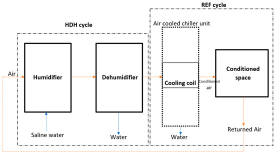
Figure 5.
Simple HDH–REF cycle.
In a similar fashion, vapor absorption refrigeration (VAR) cycles could be used with the HDH process in place of the VCR cycles. Chiranjeevi and Srinivas [68,69] in their studies provided holistic analysis and results for the HDH–VAR cycles. In such a system, freshwater is first attained through the air-cooling dehumidifiers, after which chilled water from the VAR unit is used to increase freshwater production while simultaneously providing conditioned air. The use of solar flat plate collectors (FPCs) and concentrating collectors have been recommended to satisfy the heating demand of the HDH–VAR cylces. It was further demonstrated that the HDH–VAR system displayed improved performance at higher evaporator exit temperatures and higher humidifier effetiveness.
Despite the numerous studies conducted on the HDH–Refrigeration (HDH–REF) cycles, no verifible results were obtained in terms of water productivity, air condition quality, energy utilization factor (EUF) and total operating cost (TOC) savings. The varying results were attributed to the different types of refrigeration cycles used and the configuration of the system. Generally, VCR cycles were recommended for application in hot and humid regions as it boosted the performance of the HDH–VCR system. Strong emphasis was made on the proper selection of location of the evaporator of the cycle for maximized productivity. Similarly, optimization of the feedwater concentration, humidifier effectiveness, and evaporator temperatures were recommended for improved HDH–VAR performances.
Further optimization of the HDH–REF cycle was explored by utilizing the heating load of the refrigeration cycle in the HDH process. Lawal [56] studied the efficiency of using the VCR condenser to heat the feedwater to the humidifier or to increase the temperature of the inlet for humid air entering the dehumidfier. It was further reported that AH cycles yielded more favorable energy and exergetic results. He et al. [70,71] studied the thermodynamic performanc of the HDH–VCR system wherein the VCR was used to transfer heat from the discharged brine to raise the VCR condenser feedwater temperature. It was reported that the GOR of this system increased from 4.91 to 5.14. An increase in freshwater productivity was observed at a lower pinch temperature difference of the VCR condenser. Furthermore, although elevated pressure was favorable in the VCR cycle to increase water production, it was essential to operate the cycle at optimal pressure as elevated pressures translates to higher power consumption. In their studies Rostamzadeh [72] mathematically modeled a HDH–VAR cycle using ammonia and water. In this system, the waste heat from the discharged brine was recovered by the cooling effect of the VAR desorber while the heating effect of the VAR was used to heat the HDH cycle.
Dehghani [73] investigated the use of a direct contact humidifier in a HDH–REF cycle. They noted that a fully coupled HDH–REF could eliminate the need for additional coolers by adjusting the mass flowrate ratio of seawater to dry air or seawater to freshwater. A set up similar to that investiagted by Dehghani [73] was studied by Zhang [74]. In their set-up, however, the heating and cooling load of the VCR cycle was recovered through separate heat exchangers. They claimed that a maximized GOR is attained at an optimium air flowrate value. Furthermore, the results indicated that the system’s productivity was influenced by the seawater inlet temperature at the dehumidifier while the air inlet temperature had negligible affect on the performance. Further studies conducted indicated that an increase in seawater flowrate is linked with increase yield while maximum productivity is attained through an optimized air flowrate. Shafii [75] attempted to reduce the number of heat exchangers used in the HDH–REF process by replacing the conventional HDH dehumidifier with the evaporator of the VCR cycle. An increase in freshwater yield and GOR was observed at a higher relative humidity and VCR evaporator air flowrate. An increase in the ambient temperature of the system aided in attaining a higher freshwater yield, although the GOR value decreased due to the increased energy consumption of the compressor.
Table 1 summarizes the notable observation from various HDH–REF studies conducted while Table 2 is used to provide a comparison of the heating and cooling cycles used in the HDH–REF cycles.

Table 1.
Observations from various HDH–REF processes.
Table 2.
Summary of performance of various HDH–REF cycles.
To recapitulate, numerous studies have been dedicated to the study of the optimization of the HDH desalination system through its hybridization with refrigeration cycles, and in particular the VCR system. The VCR unit was primarily used to increase the temperature of the feedwater or air. The cooling effect of the VCR was also utilized to decrease the inlet saline water temperature for improved dehumidification and subsequently increased freshwater production. The studies were developed further to determine the best dehumidication unit for increased efficiency and performance.
5.2.2. HDH and Power Cycles
Growing population and industrialization has placed stress on water and energy demands. It has been projected that by 2050, the demand for freshwater may increase by 50% while energy demands will increase by 100% [77,78]. Scarce water resources and rapidly depleting fossil fuels have created an urgent need for the development of promising technologies that are capable of satisfying both water and energy needs globally. Humidification–dehumidification desalination paired with power cycles have been suggested for the cogeneration of freshwater and electricity.
The humidification–dehumidification power cycles (HDH–PWR) are generally driven by renewable heat sources or waste heat sources and therefore not only produce freshwater and energy but also generate low levels of pollution. Ariyanfar [79] reported that the HDH–PWR sytem provided better advantages over reverse osmosis–power hybrid systems. While limited experimental studies have been conducted on HDH–PWR systems, the theoretical works available primarily consist of the organic Rankine cycles (ORCs) as the power cycle. This is mainly because ORCs are simple and flexible in design while also providing reliable results. Furthermore, ORCs are able to utilize low-grade heat sources.
He et al. (2016) [43] studied an HDH–ORC system wherein the hot brine of the HDH cycle was used as a heat source for the ORC. It was reported that controlling parameters such as the inlet water temperature to the humidifier can optimize the performance of the system. Ariyanfar [79] conducted a thermoeconomic study of an HDH–ORC cycle. Their study analyzed the impact of various system configurations and different organic fluids on the performance of the process. It was concluded that coupling the HDH with the condenser of the ORC yielded more economical results and that n-heptane increased freshwater yield at a lower unit cost. In a similar study, He et al. [43] conducted a thermodynamic analysis of pairing the ORC condenser as the heater for the HDH cycle. They observed that freshwater yield could be increased by decreasing the pinch temperature of the ORC condesner. He et al. [43] further reported that for an HDH–ORC system, in order to boost the performance of the ORC, the brine entering the evaporator was reheated using a boiler. Moreover, the maximum efficiency and GOR was achieved as an optimal saline water to air mass flowrate ratio. Thermoeconomic results of a regenerative HDH–ORC system powered by geothermal water concluded that the ORC vapor generator displayed maximum irreversibility [70]. Besides, rasising the ORC evaporator temperature yielded beneficial thermodynamic and economical results. Studies were also conducted on a HDH–PWR system that employed a flashing Rankine system instead of an ORC and geothermal water as a heat source.
The results showed that lower temperatures of seawater and a lower temperature difference of saline water in the heat exchanger improved the performance of the process [70]. Employing a single extraction ORC with a WH–HDH process displayed an increase in freshwater productivity while net power decreased when the extracton pressure of the system was raised [71]. The advantage of this system was in the various amounts of power and water generated by controlling the extraction parameters, a benefit unseen in other HDH–PWR systems.
Sayyaadi [80] proposed coupling the HDH process with a Stirling engine (SE) [24] for the cogeneration of water and power. In this HDH–SE system, waste thermal energy from the SE was supplied to the HDH unit. The objective to optimize the HDH–SE process for maximized water productivity and power generation with minimal cost was achievd through a multi-extraction HDH–SE cycle. Furthermore, the mentioned system exhibited a reliable performance at varying salinity levels of seawater.
Among the several studies conducted on the HDH–PWR systems, varying values of freshwater productivity and power generation have been reported. An important parameter often not emphasized in these systems is the thermal efficiency, which is defined using Equation (4):
where is the freshwater production rate, is the latent heat of evaporation of desalinated water, and W and are the power generated and input power, respectively.
The diverse results reported in the studies conducted on the HDH–PWR system is mainly attributed to the difference in configuration, power cycles, heat sources, and operating conditions employed in the study. Furthermore, while the HDH–PWR system has been studied from a thermo-economic standpoint, the cost of freshwater has been neglected by many [81].
Table 3 summarizes the innovations employed in the HDH–PWR cycles with the results obtained.
Table 3.
Summary of performance of various HDH–PWR cycles.
5.2.3. HDH and Other Systems
Research to enhance the performance of the HDH combined cycles have led to the inclusion of multi-generation systems (MGR) that are capable of not only generating freshwater and power but also provide heating or cooling loads, and in some cases the production of hydrogen. Ghaebi [82] conducted a thermo-economic analysis of an MGR system consisting of a Kalina cycle, VAR refrigeration cycle and WH–HDH process. They aimed to maximize the energy efficiency of the system while lowering the cost. They reported a maximum thermal efficiency of 94.8% and exergy efficiency of 47.8%. Sadeghi [83] investigated the thermodynamic behavior of an HDH–ORC cycle integrated with an ejector refrigeration cycle. They reported a maximum exergy efficiency of 17.1%. Although various PWR and REF cycles have been investigated for integration in HDH–MGR systems, the ORC, Kalina, and Rankine cycles were most studied. Similarly, VAR cycles were the preferred option to provide cooling in the refrigeration cycles. Furthermore, it should be highlighted that the MGR cycles are compatible with different sources of heat such as air, water, geothermal energy, and biogas.
Investigation to improve the efficiencies of the desalination process showed that combining HDH cycles with other desalination (DES) processes improved the overall productivity and efficiency of the process compared to the standalone systems. Mistry [50] conducted a theoretical analysis of an HDH–RO system with the aim of optimizing the hybrid system. They observed that coupling the HDH–thermal vapor compressor (TVC) with an RO unit provided results that outperformed the multi-stage flash (MSF) evaporator and multi-effect distillation (MED) in terms of GOR and energy consumption. Mahmoud [84] investigated the performance of the HDH system integrated with solar stills. They reported that the productivity declined with an increasing basin height and recommended modification to the hybrid system for improved performance. Integrating a flashing evaporator (FE) with the HDH system was suggested by Kabeel [85]. They claimed that the HDH–FE process paired with a solar air heater provided the most economical layout.
5.2.4. Innovations in HDH Design
Among the several innovations suggested to the HDH process, mechanical compression of vapor is perhaps the most debated of them. HDH desalination integrated with vapor compression entails humidified air to be compressed to high pressures in order to elevate its pressure and temperature. Condensation of the water vapor present in the humidified air then occurs when the compressed air is cooled by the saline feedwater. The prime disadvantage associated with the mechanical vapor compression (MVC) method is its high-power consumption. El-Dessouky and Ettouney [86] claim that the power consumption of MVC may exceed that of single-effect MVC and RO processes without proper control and management. Limited research has been conducted on the potential of the HDH–MVC integrated system; however, the unexplored potential of an HDH–MVC system is highlighted through the advantages provided by a MVC unit integrated with a multi-effect desalination (MED) unit. Therefore, the following sections are dedicated to detailing the MED process and to presenting the benefits of an MED–MVC integrated system.
6. Multi-Effect Desalination
While freshwater sources are already scarcely available, domestic, and industrial pollution of these resources has further limited their use. Moreover, there is an uneven natural distribution of freshwater sources, with most regions and countries lacking access to this. Considering the presented challenge, the desalination of sea water and brackish water is thought to be a promising solution. While desalination makes potable water accessible to all, the high energy input and in turn the high cost required by the process presents severe challenges to several regions incapable of meeting the energy or capital demands. Increased dependence on desalination technologies has also placed stress on the fossil fueled energy sector, further creating environmental concerns. It has been reported that 203 million tons of oil is required per year to generate 22 million cubic meters of desalinated water a day [87]. Rapidly depleting fossil fuel sources and growing environmental concerns have promoted the research and development of novel technologies that meet freshwater demands while minimizing its carbon footprint. The use of renewable sources of energy for desalination could potentially replace conventional desalination; however, without further technological advancement these alternatives cannot compete with the production cost of conventional methods.
Thermal desalination is known to be the preferred method of procuring freshwater in many countries and in particular regions with adequate fossil fuel reserves. The technology adopted by these regions is predominantly multi-effect desalination (MED). MED, although considered a mature technology, is still under constant development and optimization to produce clean water at a cost-efficient rate and lowered energy consumption. It has been reported that a single MED unit can generate 8 Million Imperial gallons per day [88] of freshwater while providing a gain output ratio between 8 and 16 [89]. Despite the impressive production capacity, only 9% of the registered desalination plants employ the MED technology. Figure 6 and Figure 7 serve to provide a graphical comparison of the various desalination technologies against the MED process.
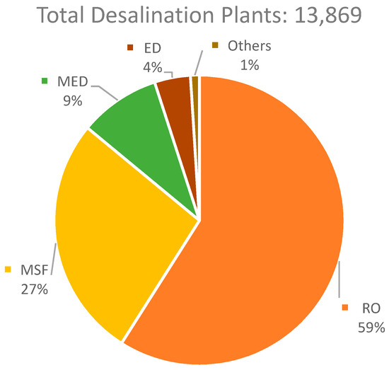
Figure 6.
Desalination methods application.
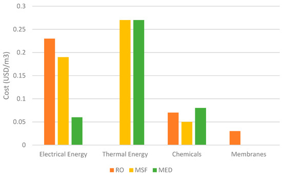
Figure 7.
Global desalination technology comparison [90].
Outwardly, MED appears to be deceptively simple in design with multiple effects or stages employed to attain water of increasing purity in each stage. The foremost design problem associated with the method is determining the optimal number of effects for the economical production of water. This further depends on the composition of the feedwater and the volatility of the pollutants present. The objective of the design would then be to optimize the number of effects and the temperature condition of each effect. From an economical perspective, the design influences the total annual cost (TAC) with the vessel size and heat transfer area impacting the capital investment with the energy (steam) demanded by the process affecting the operating costs. Plainly, while a larger number of effects may seem favorable to lower the energy consumption, the increase in subsequent capital investment must be considered [91]. Several studies have been conducted integrating MED technologies with other unit processes for increased optimization and pairing the MED process with a thermal vapor compression (TVC) system, claiming noticeable effectiveness and economic efficiency with an increased ease in operation and maintenance [88,89,90,91,92]. The results produced by an integrated cycle power plant with MED was analyzed by Almutairi [93]. The optimization of the operating conditions was performed in their successive study and by Hafdhi [94], to generate distillate water at a low production cost and high exergy efficiency, while Ghaebi [95] presented the cogeneration of power and potable water by integrating a MED–TVC process with a cooling unit and a gas turbine. Optimization studies to achieve the best balance between the exegetic efficiencies of the MED units and reverse osmosis (RO) systems in an integrated MED–RO process were also carried out by several researchers [96].
The prime advantage of MED units over other available thermal desalination methods is the ability of the system to use renewable sources of energy and waste heat sources for its operation [97], and several studies have been dedicated to the optimization of the MED system using renewable energy sources. Baccioli [98] employed waste heat from an organic Rankine cycle to operate a MED unit. The investigated system was reported to have a lowered payback time with an improved investment cost. Performance enhancement of the MED processes using low-temperature sources were studied by Dastgerdi [99] who later proposed three MED systems, namely, boosted MED (B–MED), flash boosted MED (FB–MED), and distributed boosted MED (DB–MED) with the DB–MED system providing superior results. Ansari [100] provided the MED–TVC unit with high temperature steam using a pressurized water reactor. They observed a decline in total capital investment cost, exergy destruction cost and water cost after economic optimization was conducted.
Although the MED technology can be integrated with low heat renewable sources of energy, their performance can be enhanced using heat pump cycles (HPC). HPC are units capable of converting a low temperature heat sink to high temperature heat sources through mechanical compression of refrigerants. The application of absorption heat pump cycles (AHPCs) with the solar based MED plants was met with positive results wherein it was claimed that the area of the solar collector could be reduced by half, in contrast to conventional solar MED processes [101]. Following the promising results from the AHPC–MED process, HPCs were applied to other desalination processes such as the humidification–dehumidification (HDH) desalination technology with appealing preliminary results when Capocelli and Esfahani [102,103] combined an AHPC–MED process with an open cycle vapor compression refrigeration system. It was reported that the system could reduce the total annual cost by 25.6% while increasing the exergy efficiency by 4.75% compared to conventional desalination systems.
Although the AHPC is a modification of the vapor compression heat pump, it displays a greater coefficient of performance [104] and lower vapor pressure. As a result, it requires lower compression power and can provide a higher supply temperature. Despite this, the VCHPs ability to use steam circulating within the cycles is linked with enhanced performance as steam can be injected or rejected as needed.
It is evident that the MED technology and its subsequent integration with other technologies have promising industrial applications with the appropriate optimization. The following section serves to highlight and review existing studies on the MED–MVC cycles, with particular emphasis on its thermo-economic results.
MED–MVC System
The MED-MVC technology is not to be thought of as a new-found technology but rather one that has been long since applied to medium-scale desalination and salt recovery [105]. Integrating the MED technology with MVC systems was claimed to provide an improved water quality. The overall process also requires compact equipment, has a low-temperature design and provides stable long-term operation. Minimal corrosion and scale formation further makes the integration favorable [106]. Despite this, the limitations of the integrated system, such as the low capacity of the MVC and the low volumetric flowrate limiting the production capacity, overshadow the advantages of the system and have prevented its application for large-scale operations [107].
The MED–MVC integrated system is a cyclic process wherein the vapor from the last stage of the MED unit is directed to the MVC through a demister to separate water and vapor. The vapor in the MVC is then compressed to the desired operating condition before using it to supply steam to the first effect of the MED. The steam supplied by the MVC condenses to distillate in the first effect of the MED tube-side. This occurs by transferring the latent heat to the saline feedwater sprayed around the tubes. A small portion of the saline feedwater then evaporates and is used as a heat source for the second MED stage. By employing the MVC unit, the vapor from the last stage of the MED unit is used as a heating source for the feedwater thereby eliminating the need of a condenser typically required in conventional MED systems. Figure 8 presents a simple schematic of an integrated MED–MCV process.
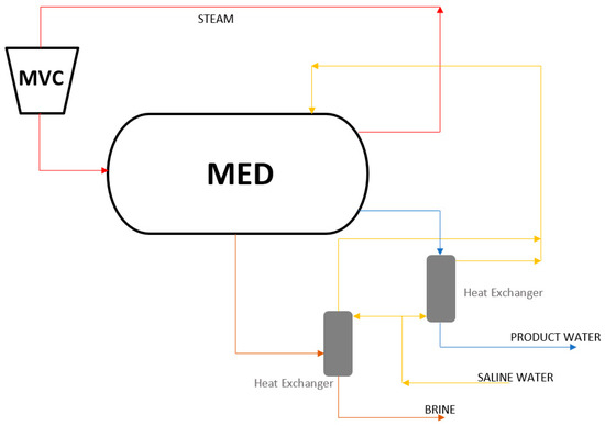
Figure 8.
MED–MVC process.
Various studies on the MVC technologies were conducted to develop steady state models that simplified the design and optimized performance. Veza [108] proposed an MVC desalination set up capable of producing 500 m3 distilled water/day while operating at a specific power consumption (SPC) of 11.5 kWh/m3. In a similar study, Lucas [109] designed an MVC desalination unit with a production capacity of 1500 m3/day and SPC of 11 kWh/m3. Both the above proposed systems were operated at a 40% water recovery. The MVC pilot plant investigated by Bahar [110] involved the use of vertical double fluted tube evaporators of 1 m3/day capacity, and a top brine temperature (TBT) of 103 °C. The highest recorded performance ratio (PR) of this system was found to be 2.52. Aly [111] analyzed the performance of a single effect MVC system producing 5 m3 distilled water/day through mathematical modelling. The steam supply was regulated using feed seawater temperature and the compressor power.
Shaffer [112] suggests the application of the MVC process beyond seawater desalination and to produced water [1] and wastewater treatment. Koren [113] employed a single effect MVC system to separate oil and water from a high salinity mixture and their system was able to achieve a production capacity of 600 m3 freshwater/day operating at a SPC of 13.6 kWh/m3. Meanwhile, Wu [104] conducted studies on a novel MVC system for sewage treatment and their design separated the evaporator and condenser in an effort to overcome the shortcomings of traditional MVC systems with a capacity of 1.44 m3/day.
According to Sharqawy [114], exergy analysis involves identifying the components in a process with the highest thermodynamic irreversibility rate. Bearing in mind the aforementioned concept, Alasfour [115] studied the steady-state model of a single effect MVC unit using the second law of thermodynamics. They observed an increase in the unit’s exergy destruction with an increase in temperature difference across the stages, while a study conducted by Jamil [116] involved an exergo-economic analysis of a forward feed MED–MVC configuration. Using the second law of efficiency, the SPC and product cost were all reported to increase as the number of stages were increased from two to six. Furthermore, the exergy destruction obtained in their configuration was far lower than those stated in the literature [117].
The variation in design of an MED–MVC system predominantly comes from the configurations of the MED unit. Elsayed [117] analyzed four configurations to determine their effect on the performance of a 4-effect MED–MVC system. The configurations considered were forward feed (FF), parallel feed (PF), backward feed (BF) and parallel/cross feed (PCF). The modelled MED–MVC design was validated against actual data obtained from plants located in Spain and India with an overall deviation within 7% in both cases [108,109,110,111,112,113,114,115,116,117,118]. To gain a comparison of the different configurations studied from an exergo-economic perspective, the first and second laws of thermodynamics were employed. Using the first law of thermodynamics it was reported that the FF and the PCF provided superior function in terms of PR and utilized less power to produce the same amount of freshwater.
Few efforts have been taken to investigate the dynamic model of the MED–MVC system. El-Khatib et al. [119] proposed to study the transient behavior of a single effect MED–MVC unit by controlling various process input and outputs. By varying the distillate flowrate and the feed flow rate, the dynamics of the vapor temperature inside the stages were analyzed; however, their results were not verified against actual data or experimental outputs. Studies conducted by Kishore et al. [118] aimed to understand the dynamic behavior of the MED–MVC unit through a simulator and they found that the load had no observable change on the system’s response. Conducting further research on the dynamic behavior of the MED–MVC process is paramount since it aids in the enhancement of the performance.
Table 4 aims to summarize the application of the MED–MVC process in various locations with their production capacity and SPC.
Table 4.
Summary of studies conducted on MED–MVC systems.
7. Conclusions
The various benefits of volume reduction for produced water treatment were explored. Freeze concentration, while offering a lower energy consumption compared against conventional desalination methods and a lower equipment corrosion, is often limited in commercial applications of the process due to large separation energy costs. The potential of RO systems is often limited due to extensive fouling of the membranes and integration of the RO process with appropriate pre-treatment methods has been suggested. Low-grade energy use and simple design and construction has made the HDH technology a novel PW treatment method. The process encounters slight drawbacks in terms of freshwater production, however, integration of the process with refrigeration cycles and power cycles has indisputable potential and the VCR unit is favored for the HDH–refrigeration process. A diverse range of results were obtained for the HDH–power cycles mainly due to the different configurations, heat sources and operating conditions possible; however, more insight and studies are needed to evaluate the cost of freshwater produced by the process. Finally, the mechanical vapor compression systems were reviewed with the high energy consumption of the process a prime disadvantage of the system; however, studies integrating this system with MED systems have promoted an improved exergy efficiency. Although the potential of HDH and MVC systems have been recognized by many, little to no data is available providing distinguished economic analysis for these processes. It is suggested that increasing attention to the economic aspects of the HDH and MVC processes while also focusing on the optimization of the system in terms of thermodynamics, design and performance would lead to an increase in interest of these systems not only in terms of research but also for industrial application.
Author Contributions
Conceptualization, all authors.; resources M.K.; data curation, M.I.; writing—original draft preparation, M.K. and M.I.; writing—review and editing, F.A. and S.A.; supervision, M.K., F.A. and S.A.; project administration, M.K.; funding acquisition, M.K. and F.A. All authors have read and agreed to the published version of the manuscript.
Funding
QNRF for grant UREP27-040-2-014; Qatar University grant IRCC-2020-016.
Data Availability Statement
Exclude this statement.
Acknowledgments
The contents herein are solely the responsibility of the authors. In addition, the work was made possible by an Internal Qatar University grant IRCC-2020-016. In addition, the authors would like to acknowledge QNRF for grant UREP27-040-2-014.
Conflicts of Interest
The authors declare no conflict of interest.
References
- Ahmadizadeh, R.; Shokrollahzadeh, S.; Latifi, S.M.; Samimi, A.; Pendashteh, A. Application of halophilic microorganisms in osmotic membrane bioreactor (OMBR) for reduction of volume and organic load of produced water. J. Water Process. Eng. 2020, 37, 101422. Available online: http://www.sciencedirect.com/science/article/pii/S2214714420303007 (accessed on 5 November 2021). [CrossRef]
- Ground Water Protection Council. Produced Water Report: Regulations, Current Practices, and Research Needs; Ground Water Protection Council: Oklahoma, OK, USA, 2019. [Google Scholar]
- Kusworo, T.D.; Aryanti, N.; Qudratun; Utomo, D.P. Oilfield produced water treatment to clean water using integrated activated carbon-bentonite adsorbent and double stages membrane process. Chem. Eng. J. 2018, 347, 462–471. Available online: http://www.sciencedirect.com/science/article/pii/S1385894718307095 (accessed on 17 June 2021). [CrossRef]
- Mccabe, P.J. Oiloiland Natural Gasnatural gas: Global Resourcesnatural Gasglobal Resources. In Encyclopedia of Sustainability Science and Technology; Meyers, R.A., Ed.; Springer: New York, NY, USA, 2012; pp. 7446–7456. ISBN 9781441908513. [Google Scholar]
- Global Water Intelligence. Produced Water Market: Opportunities in the Oil, Shale and Gas Sectors in North America; Media Analytics Ltd.: Oxford, UK, 2011. [Google Scholar]
- Burnett, D.B.; Siddiqui, M. Recovery of Fresh Water Resources from Desalination of Brine Produced during Oil and Gas Production Operations; Texas Engineering Experiment Station: Eastmark Dr, TX, USA, 2006. [Google Scholar]
- United Nations. SDG 6 Synthesis Report 2018 on Water and Sanitation; United Nations: London, UK, 2018. [Google Scholar]
- Kang, H.; Wang, T.; Zheng, H. Comparative analysis of regenerative and air-extraction multi-stage humidification–dehumidification desalination system using pinch technology. Desalination 2016, 385, 158–166. Available online: http://www.sciencedirect.com/science/article/pii/S0011916416300509 (accessed on 17 June 2021). [CrossRef]
- Visvanathan, C.; Svenstrup, P.; Ariyamethee, P. Volume reduction of produced water generated from natural gas production process using membrane technology. Water Sci. Technol. 2000, 41, 117–123. [Google Scholar] [CrossRef]
- Janks, J.; Cadena, F. Investigations Into the Use of Modified Zeolites for Removing Benzene, Toluene, and Xylene from Saline Produced Water. In Produced Water; Ray, J.P., Engelhardt, F.R., Eds.; Springer: Boston, MA, USA, 1992; pp. 473–487. [Google Scholar]
- Adewumi, M.; Erb, J.; Watson, R. Initial Design Considerations for a Cost Effective Treatment of Stripper Oil Well Produced Water. In Produced Water; Ray, J.P., Engelhardt, F.R., Eds.; Springer: Boston, MA, USA, 1992; pp. 511–522. [Google Scholar]
- Van den Broek, W.M.; Plat, R.; van der Zande, M.J. Comparison of plate separator, centrifuge and hydrocyclone. In Proceedings of the SPE International Oil and Gas Conference and Exhibition in China: Society of Petroleum Engineers, Beijing, China, 2–6 November 1998. [Google Scholar]
- Zhou, F.S.; Zhao, M.F.; Ni, W.X.; Dang, Y.S.; Pu, C.S.; Lu, F.J. Inorganic polymeric flocculent FMA for purifying oilfield produced water: Preparation and uses. Oilfield Chem. 2000, 17, 256–259. [Google Scholar]
- Houcine, M. Solution for heavy metals decontamination in produced water/case study in southern Tunisia. In Proceedings of the SPE International Conference on Health, Safety and Environment in Oil and Gas Exploration and Production: Society of Petroleum Engineers, Kuala Lumpur, Malaysia, 20–22 March 2002. [Google Scholar]
- Stepnowski, P.; Zaleska, A. Comparison of different advanced oxidation processes for the degradation of room temperature ionic liquids. J. Photochem. Photobiol. A Chem. 2005, 170, 45–50. Available online: http://www.sciencedirect.com/science/article/pii/S1010603004003727 (accessed on 23 December 2021). [CrossRef]
- Ganiyu, S.O.; Zhou, M.; Martínez-Huitle, C.A. Heterogeneous electro-Fenton and photoelectro-Fenton processes: A critical review of fundamental principles and application for water/wastewater treatment. Appl. Catal. B Environ. 2018, 235, 103–129. [Google Scholar] [CrossRef]
- Zhang, H.; Liu, J.; Ou, C.; Shen, J.; Yu, H.; Jiao, Z.; Han, W.; Sun, X.; Li, J.; Wang, L. Reuse of Fenton sludge as an iron source for NiFe2 O4 synthesis and its application in the Fenton-based process. J. Environ. Sci. 2017, 53, 1–8. [Google Scholar] [CrossRef]
- McFarlane, J.; Ridenour, W.B.; Luo, H.; Hunt, R.D.; DePaoli, D.W.; Ren, R.X. Room Temperature Ionic Liquids for Separating Organics from Produced Water. Sep. Sci. Technol. 2005, 40, 1245–1265. [Google Scholar] [CrossRef]
- Madaeni, S. The application of membrane technology for water disinfection. Water Res. 1999, 33, 301–308. [Google Scholar] [CrossRef]
- Ciarapica, F.; Giacchetta, G. The treatment of produced water in offshore rig: Comparison between tradition installations and innovative systems. In Proceedings of the 5th International Membrane Science & Technology Conference, University of New South Wales, Sydney, Australia, 10–14 November 2003. [Google Scholar]
- Samsuri, S.; Rizan, N.A.N.; Hung, S.H.; Amran, N.A.; Sambudi, N.S. Progressive Freeze Concentration for Volume Reduction of Produced Water and Biodiesel Wastewater. Chem. Eng. Technol. 2019, 42, 1764–1770. [Google Scholar] [CrossRef]
- Rogers, G.F.C.; Mayhew, Y.R. Thermodynamic and Transport Properties of Fluids; John Wiley & Sons: Hoboken, NJ, USA, 1995; ISBN 0631197036. [Google Scholar]
- Samsuri, S.; Amran, N.A.; Yahya, N.; Jusoh, M. Review on Progressive Freeze Concentration Designs. Chem. Eng. Commun. 2015, 203, 345–363. [Google Scholar] [CrossRef]
- Oh, S.-Y.; Binns, M.; Cho, H.; Kim, J.-K. Energy minimization of MEA-based CO2 capture process. Appl. Energy 2016, 169, 353–362. [Google Scholar] [CrossRef]
- Halde, R. Concentration of impurities by progressive freezing. Water Res. 1980, 14, 575–580. [Google Scholar] [CrossRef]
- Williams, P.M.; Ahmad, M.; Connolly, B.; Oatley-Radcliffe, D.L. Technology for freeze concentration in the desalination industry. Desalination 2015, 356, 314–327. [Google Scholar] [CrossRef]
- Lu, Z.; Xu, L. Freezing desalination process. Therm. Desalination Process. 2010, 2, 10. [Google Scholar]
- Weiss, P.A. Thermal Desalination Processes. Volume 2. 1973. Available online: https://openlibrary.org/works/OL19136062W/Practice_of_desalination (accessed on 24 November 2021).
- Rahman, M.S.; Ahmed, M.; Chen, X.D. Freezing—Melting process and desalination: I. Review of the state-of-the-art. Sep. Purif. Rev. 2006, 35, 59–96. [Google Scholar] [CrossRef]
- Shafiur Rahman, M.; Ahmed, M.; Chen, X.D. Freezingmelting process and desalination: Review of present status and future prospects. Int. J. Nucl. Desalination 2007, 2, 253–264. [Google Scholar] [CrossRef]
- Tao, F.T.; Curtice, S.; Hobbs, R.D.; Sides, J.L.; Wieser, J.D.; Dyke, C.A.; Tuohey, D.; Pilger, P.F. Reverse osmosis process successfully converts oil field brine into freshwater. Oil Gas J. USA 1993, 91, 38. [Google Scholar]
- Ahmed, I. Importance and Significance of UF/MF Membrane Systems in Desalination Water Treatment; IntechOpen: London, UK, 2017; Available online: https://books.google.co.in/books?id=71ifzQEACAAJ (accessed on 24 November 2021).
- Mondal, S.; Wickramasinghe, S.R. Produced water treatment by nanofiltration and reverse osmosis membranes. J. Membr. Sci. 2008, 322, 162–170. [Google Scholar] [CrossRef]
- McGinnis, R.L.; Hancock, N.T.; Nowosielski-Slepowron, M.S.; McGurgan, G.D. Pilot demonstration of the NH3/CO2 forward osmosis desalination process on high salinity brines. Desalination 2013, 312, 67–74. [Google Scholar] [CrossRef]
- Chen, G.; Wang, Z.; Nghiem, L.; Li, X.-M.; Xie, M.; Zhao, B.; Zhang, M.; Song, J.; He, T. Treatment of shale gas drilling flowback fluids (SGDFs) by forward osmosis: Membrane fouling and mitigation. Desalination 2015, 366, 113–120. [Google Scholar] [CrossRef] [Green Version]
- McGovern, R.K.; Lienhard, V.J.H. On the potential of forward osmosis to energetically outperform reverse osmosis desalination. J. Membr. Sci. 2014, 469, 245–250. [Google Scholar] [CrossRef] [Green Version]
- Bartholomew, T.; Mey, L.; Arena, J.T.; Siefert, N.S.; Mauter, M.S. Osmotically assisted reverse osmosis for high salinity brine treatment. Desalination 2017, 421, 3–11. [Google Scholar] [CrossRef]
- Kim, J.; Kim, D.I.; Hong, S. Analysis of an osmotically-enhanced dewatering process for the treatment of highly saline (waste)waters. J. Membr. Sci. 2018, 548, 685–693. [Google Scholar] [CrossRef]
- Kim, J.; Kim, J.; Kim, J.; Hong, S. Osmotically enhanced dewatering-reverse osmosis (OED-RO) hybrid system: Implications for shale gas produced water treatment. J. Membr. Sci. 2018, 554, 282–290. [Google Scholar] [CrossRef]
- Zhang, L.-Z.; Huang, S.-M. Coupled heat and mass transfer in a counter flow hollow fiber membrane module for air humidification. Int. J. Heat Mass Transf. 2011, 54, 1055–1063. [Google Scholar] [CrossRef]
- Li, G.-P.; Qi, R.-H.; Zhang, L.-Z. Performance study of a solar-assisted hollow-fiber-membrane-based air humidification-dehumidification desalination system: Effects of membrane properties. Chem. Eng. Sci. 2019, 206, 164–179. [Google Scholar] [CrossRef]
- Zhang, T.; Zhang, L.-Z. Development of a MXene-based membrane with excellent anti-fouling for air humidification-dehumidification type desalination. J. Membr. Sci. 2022, 641, 119907. [Google Scholar] [CrossRef]
- He, W.; Han, D.; Xu, L.; Yue, C.; Pu, W. Performance investigation of a novel water–power cogeneration plant (WPCP) based on humidification dehumidification (HDH) method. Energy Convers. Manag. 2016, 110, 184–191. [Google Scholar] [CrossRef]
- Kabeel, A.E.; Hamed, M.H.; Omara, Z.M.; Sharshir, S.W. Water Desalination Using a Humidification-Dehumidification Technique—A Detailed Review. Nat. Resour. 2013, 4, 286–305. [Google Scholar] [CrossRef] [Green Version]
- Hamed, M.H.; Kabeel, A.; Omara, Z.; Sharshir, S. Mathematical and experimental investigation of a solar humidification–dehumidification desalination unit. Desalination 2015, 358, 9–17. [Google Scholar] [CrossRef]
- El-Dessouky, H.T. Humidification-dehumidification desalination process using waste heat from a gas turbine. Desalination 1989, 71, 19–33. [Google Scholar] [CrossRef] [Green Version]
- Al-Hallaj, S.; Farid, M.; Tamimi, A.R. Solar desalination with a humidification-dehumidification cycle: Performance of the unit. Desalination 1998, 120, 273–280. [Google Scholar] [CrossRef]
- Narayan, G.P.; Sharqawy, M.H.; Leinhard, V.J.H.; Zubair, S.M. Thermodynamic analysis of humidification dehumidification desalination cycles. Desalination Water Treat. 2010, 16, 339–353. [Google Scholar] [CrossRef] [Green Version]
- Mistry, K.H.; Lienhard, J.H.; Zubair, S.M. Effect of entropy generation on the performance of humidification-dehumidification desalination cycles. Int. J. Therm. Sci. 2010, 49, 1837–1884. [Google Scholar] [CrossRef] [Green Version]
- Mistry, K.H.; Mitsos, A.; Lienhard, J.H. Optimal operating conditions and configurations for humidification–dehumidification desalination cycles. Int. J. Therm. Sci. 2011, 50, 779–789. [Google Scholar] [CrossRef] [Green Version]
- Sharqawy, M.H.; Antar, M.A.; Zubair, S.M.; Elbashir, A. Optimum thermal design of humidification dehumidification desalination systems. Desalination 2014, 349, 10–21. [Google Scholar] [CrossRef]
- Narayan, G.P.; McGovern, R.K.; Zubair, S.M.; Lienhard, J.H. High-temperature-steam-driven, varied-pressure, humidification-dehumidification system coupled with reverse osmosis for energy-efficient seawater desalination. Energy 2012, 37, 482–493. [Google Scholar] [CrossRef]
- Siddiqui, O.K.; Sharqawy, M.H.; Antar, M.A.; Zubair, S.M. Performance evaluation of variable pressure humidification-dehumidification systems. Desalination 2017, 409, 171–182. [Google Scholar] [CrossRef]
- Hawlader, M.; Dey, P.K.; Diab, S.; Chung, C.Y. Solar assisted heat pump desalination system. Desalination 2004, 168, 49–54. [Google Scholar] [CrossRef]
- Gude, V.G.; Nirmalakhandan, N. Combined desalination and solar-assisted air-conditioning system. Energy Convers. Manag. 2008, 49, 3326–3330. [Google Scholar] [CrossRef]
- Lawal, D.U.; Antar, M.; Khalifa, A.; Zubair, S.; Al-Sulaiman, F. Humidification-dehumidification desalination system operated by a heat pump. Energy Convers. Manag. 2018, 161, 128–140. [Google Scholar] [CrossRef]
- Kassim, M.A.; Benhamou, B.; Harmand, S. Effect of air humidity at the entrance on heat and mass transfers in a humidifier intended for a desalination system. Appl. Therm. Eng. 2011, 31, 1906–1914. [Google Scholar] [CrossRef]
- Faegh, M.; Behnam, P.; Shafii, M.B. A review on recent advances in humidification-dehumidification (HDH) desalination systems integrated with refrigeration, power and desalination technologies. Energy Convers. Manag. 2019, 196, 1002–1036. [Google Scholar] [CrossRef]
- Saidi, S.; Ben Radhia, R.; Dhifaoui, B.; Ben Jabrallah, S. Experimental study of the inclined solar film evaporator. Desalination Water Treat. 2014, 56, 2576–2583. [Google Scholar] [CrossRef]
- Klausner, J.F.; Li, Y.; Mei, R. Evaporative heat and mass transfer for the diffusion driven desalination process. Heat Mass Transf. 2005, 42, 528–536. [Google Scholar] [CrossRef]
- Müller-Holst, H.; Engelhardt, M.; Herve, M.; Schölkopf, W. Solarthermal seawater desalination systems for decentralised use. Renew. Energy 1998, 14, 311–318. [Google Scholar] [CrossRef]
- El-Agouz, S.; Abugderah, M. Experimental analysis of humidification process by air passing through seawater. Energy Convers. Manag. 2008, 49, 3698–3703. [Google Scholar] [CrossRef]
- Amer, E.; Kotb, H.; Mostafa, G.; El-Ghalban, A. Theoretical and experimental investigation of humidification–dehumidification desalination unit. Desalination 2009, 249, 949–959. [Google Scholar] [CrossRef]
- Tow, E.W.; Lienhard, J.H. Experiments and modeling of bubble column dehumidifier performance. Int. J. Therm. Sci. 2014, 80, 65–75. [Google Scholar] [CrossRef] [Green Version]
- Eslamimanesh, A.; Hatamipour, M. Mathematical modeling of a direct contact humidification–dehumidification desalination process. Desalination 2009, 237, 296–304. [Google Scholar] [CrossRef]
- Nada, S.; Elattar, H.; Fouda, A. Experimental study for hybrid humidification-dehumidification water desalination and air conditioning system. Desalination 2015, 363, 112–125. [Google Scholar] [CrossRef]
- Elattar, H.; Fouda, A.; Nada, S. Performance investigation of a novel solar hybrid air conditioning and humidification-dehumidification water desalination system. Desalination 2016, 382, 28–42. [Google Scholar] [CrossRef]
- Chiranjeevi, C.; Srinivas, T. Influence of vapor absorption cooling on humidification-dehumidification (HDH) desalination. Alex. Eng. J. 2016, 55, 1961–1967. [Google Scholar] [CrossRef] [Green Version]
- Chiranjeevi, C.; Srinivas, T. Combined two stage desalination and cooling plant. Desalination 2014, 345, 56–63. [Google Scholar] [CrossRef]
- He, W.; Han, D.; Ji, C. Investigation on humidification dehumidification desalination system coupled with heat pump. Desalination 2018, 436, 152–160. [Google Scholar] [CrossRef]
- He, W.; Yang, H.; Han, D. Thermodynamic Analysis of A Novel Humidification Dehumidification Desalination System Driven by Heat Pump. Energy Procedia 2019, 158, 6030–6037. [Google Scholar] [CrossRef]
- Rostamzadeh, H.; Namin, A.S.; Ghaebi, H.; Amidpour, M. Performance assessment and optimization of a humidification dehumidification (HDH) system driven by absorption-compression heat pump cycle. Desalination 2018, 447, 84–101. [Google Scholar] [CrossRef]
- Dehghani, S.; Date, A.; Akbarzadeh, A. Performance analysis of a heat pump driven humidification-dehumidification desalination system. Desalination 2018, 445, 95–104. [Google Scholar] [CrossRef]
- Zhang, Y.; Zhu, C.; Zhang, H.; Zheng, W.; You, S.; Zhen, Y. Experimental study of a humidification-dehumidification desalination system with heat pump unit. Desalination 2018, 442, 108–117. [Google Scholar] [CrossRef]
- Shafii, M.B.; Jafargholi, H.; Faegh, M. Experimental investigation of heat recovery in a humidification-dehumidification desalination system via a heat pump. Desalination 2018, 437, 81–88. [Google Scholar] [CrossRef]
- Fouda, A.; Nada, S.; Elattar, H. An integrated A/C and HDH water desalination system assisted by solar energy: Transient analysis and economical study. Appl. Therm. Eng. 2016, 108, 1320–1335. [Google Scholar] [CrossRef]
- Marale, S.; Chiranjeevi, C.; Srinivas, T.; Raj, R.T. Experimental and Computational Fluid Dynamics Studies on Dehumidifier in a Combined Cooling and Desalination Plant. J. Therm. Sci. Eng. Appl. 2016, 9, 011007. [Google Scholar] [CrossRef]
- Sadeghi, S.H.; Moghadam, E.S. Renewable Energy in the Water, Energy & Food Nexus; IRENA: Abu Dhabi, United Arab Emirates, 2015; pp. 1–125. [Google Scholar]
- Ariyanfar, L.; Yari, M.; Aghdam, E.A. Proposal and performance assessment of novel combined ORC and HDD cogeneration systems. Appl. Therm. Eng. 2016, 108, 296–311. [Google Scholar] [CrossRef]
- Sayyaadi, H.; Ghorbani, G. Conceptual design and optimization of a small-scale dual power-desalination system based on the Stirling prime-mover. Appl. Energy 2018, 223, 457–471. [Google Scholar] [CrossRef]
- Rostamzadeh, H.; Ghiasirad, H.; Amidpour, M.; Amidpour, Y. Performance enhancement of a conventional multi-effect desalination (MED) system by heat pump cycles. Desalination 2019, 477, 114261. Available online: http://www.sciencedirect.com/science/article/pii/S0011916419307556 (accessed on 9 July 2021). [CrossRef]
- Ghaebi, H.; Namin, A.S.; Rostamzadeh, H. Performance assessment and optimization of a novel multi-generation system from thermodynamic and thermoeconomic viewpoints. Energy Convers. Manag. 2018, 165, 419–439. [Google Scholar] [CrossRef]
- Sadeghi, M.; Yari, M.; Mahmoudi, S.; Jafari, M. Thermodynamic analysis and optimization of a novel combined power and ejector refrigeration cycle—Desalination system. Appl. Energy 2017, 208, 239–251. [Google Scholar] [CrossRef]
- Mahmoud, A.; Fath, H.; Ahmed, M. Enhancing the performance of a solar driven hybrid solar still/humidification-dehumidification desalination system integrated with solar concentrator and photovoltaic panels. Desalination 2018, 430, 165–179. [Google Scholar] [CrossRef]
- Kabeel, A.; El-Said, E.M. A hybrid solar desalination system of air humidification dehumidification and water flashing evaporation: A comparison among different configurations. Desalination 2013, 330, 79–89. [Google Scholar] [CrossRef]
- El-Dessouky, H.T.; Ettouney, H.M. Fundamentals of Salt Water Desalination; Elsevier: Amsterdam, The Netherlands, 2002; ISBN 0080532128. [Google Scholar]
- Kalogirou, S. Seawater desalination using renewable energy sources. Prog. Energy Combust. Sci. 2005, 31, 242–281. Available online: http://www.sciencedirect.com/science/article/pii/S0360128505000146 (accessed on 24 November 2021). [CrossRef]
- Choi, H.-S.; Lee, T.-J.; Kim, Y.-G.; Song, S.-L. Performance improvement of multiple-effect distiller with thermal vapor compression system by exergy analysis. Desalination 2005, 182, 239–249. Available online: http://www.sciencedirect.com/science/article/pii/S0011916405004376 (accessed on 12 May 2021). [CrossRef]
- Nannarone, A.; Toro, C.; Enrico, S. Multi-Effect Distillation Desalination Process: Modeling and Simulation. In Proceedings of the ECOS 2017—The 30th International Conference on Efficiency, Cost, Optimization, Simulation and Environmental Impact of Energy Systems, San Diego, CA, USA, 2–6 July 2017. [Google Scholar]
- Lattemann, S.; Kennedy, M.D.; Schippers, j.; Amy, G. Chapter 2 Global Desalination Situation. In Sustainability Science and Engineering; Escobar, I.C., Schäfer, A.I., Eds.; Elsevier: Amsterdam, The Netherlands, 2010; Volume 2, pp. 7–39. ISBN 18712711. [Google Scholar]
- Luyben, W.L. Dynamic simulation of multi-effect evaporators. Chem. Eng. Processing-Process Intensif. 2018, 131, 106–115. Available online: http://www.sciencedirect.com/science/article/pii/S0255270118304215 (accessed on 24 November 2021). [CrossRef]
- Al-Najem, N.M.; Darwish, M.; Youssef, F. Thermovapor compression desalters: Energy and availability—Analysis of single- and multi-effect systems. Desalination 1997, 110, 223–238. [Google Scholar] [CrossRef]
- Almutairi, A.; Pilidis, P.; Al-Mutawa, N.; Al-Weshahi, M. Energetic and exergetic analysis of cogeneration power combined cycle and ME-TVC-MED water desalination plant: Part-1 operation and performance. Appl. Therm. Eng. 2016, 103, 77–91. Available online: http://www.sciencedirect.com/science/article/pii/S1359431116302642 (accessed on 24 November 2021). [CrossRef]
- Hafdhi, F.; Khir, T.; Ben Yahia, A.; Ben Brahim, A. Exergoeconomic optimization of a double effect desalination unit used in an industrial steam power plant. Desalination 2018, 438, 63–82. Available online: http://www.sciencedirect.com/science/article/pii/S001191641731665X (accessed on 9 July 2021). [CrossRef]
- Ghaebi, H.; Abbaspour, G. Performance analysis and thermodynamic modeling of a poly generation system by integrating a multi-effect-desalination thermo-vapor compression (MED-TVC) system with a combined cooling, heating and power (CCHP) system. J. Therm. Eng. 2018, 4, 1963–1983. [Google Scholar] [CrossRef]
- Sadri, S.; Ameri, M.; Khoshkhoo, R.H. Multi-objective optimization of MED-TVC-RO hybrid desalination system based on the irreversibility concept. Desalination 2017, 402, 97–108. Available online: http://www.sciencedirect.com/science/article/pii/S001191641630385X (accessed on 9 July 2021). [CrossRef]
- Saldivia, D.; Rosales, C.; Barraza, R.; Cornejo, L. Computational analysis for a multi-effect distillation (MED) plant driven by solar energy in Chile. Renew. Energy 2018, 132, 206–220. Available online: http://www.sciencedirect.com/science/article/pii/S0960148118309364 (accessed on 24 November 2021). [CrossRef]
- Baccioli, A.; Antonelli, M.; Desideri, U.; Grossi, A. Thermodynamic and economic analysis of the integration of Organic Rankine Cycle and Multi-Effect Distillation in waste-heat recovery applications. Energy 2018, 161, 456–469. Available online: http://www.sciencedirect.com/science/article/pii/S0360544218314439 (accessed on 24 November 2021). [CrossRef]
- Dastgerdi, H.R.; Whittaker, P.B.; Chua, H.T. New MED based desalination process for low grade waste heat. Desalination 2016, 395, 57–71. Available online: http://www.sciencedirect.com/science/article/pii/S0011916416304350 (accessed on 15 May 2021). [CrossRef]
- Ansari, K.; Sayyaadi, H.; Amidpour, M. Thermoeconomic optimization of a hybrid pressurized water reactor (PWR) power plant coupled to a multi effect distillation desalination system with thermo-vapor compressor (MED-TVC). Energy 2010, 35, 1981–1996. Available online: http://www.sciencedirect.com/science/article/pii/S0360544210000150 (accessed on 24 November 2021). [CrossRef]
- Alarcón-Padilla, D.C.; García-Rodríguez, L.; Blanco-Gálvez, J. Design recommendations for a multi-effect distillation plant connected to a double-effect absorption heat pump: A solar desalination case study. Desalination 2010, 262, 11–14. Available online: http://www.sciencedirect.com/science/article/pii/S0011916410002936 (accessed on 24 November 2021). [CrossRef]
- Capocelli, M.; Balsamo, M.; Lancia, A.; Barba, D. Process analysis of a novel humidification-dehumidification-adsorption (HDHA) desalination method. Desalination 2018, 429, 155–166. Available online: http://www.sciencedirect.com/science/article/pii/S0011916417317575 (accessed on 24 November 2021). [CrossRef]
- Esfahani, I.J.; Kang, Y.T.; Yoo, C. A high efficient combined multi-effect evaporation-absorption heat pump and vapor-compression refrigeration part 1: Energy and economic modeling and analysis. Energy 2014, 75, 312–326. [Google Scholar] [CrossRef]
- Wu, H.; Li, Y.; Chen, J. Research on an evaporator-condenser-separated mechanical vapor compression system. Desalination 2013, 324, 65–71. Available online: http://www.sciencedirect.com/science/article/pii/S0011916413002737 (accessed on 24 November 2021). [CrossRef]
- Lu, H.; Wang, J.; Wang, T.; Wang, N.; Bao, Y.; Hao, H. Crystallization techniques in wastewater treatment: An overview of applications. Chemosphere 2017, 173, 474–484. Available online: http://www.sciencedirect.com/science/article/pii/S0045653517300802 (accessed on 24 November 2021). [CrossRef]
- Zimerman, Z. Development of large capacity high efficiency mechanical vapor compression (MVC) units. Desalination 1994, 96, 51–58. Available online: http://www.sciencedirect.com/science/article/pii/0011916494851565 (accessed on 24 November 2021). [CrossRef]
- Sharaf, M.; Nafey, A.; García-Rodríguez, L. Thermo-economic analysis of solar thermal power cycles assisted MED-VC (multi effect distillation-vapor compression) desalination processes. Energy 2011, 36, 2753–2764. Available online: http://www.sciencedirect.com/science/article/pii/S0360544211000934 (accessed on 24 November 2021). [CrossRef]
- Veza, J. Mechanical vapour compression desalination plants—A case study. Desalination 1995, 101, 1–10. Available online: http://www.sciencedirect.com/science/article/pii/001191649500002J (accessed on 24 November 2021). [CrossRef]
- Lucas, M.; Tabourier, B. The mechanical vapour compression process applied to seawater desalination: A 1500 ton/day unit installed in the nuclear power plant of Flamanville, France. Desalination 1985, 52, 123–133. Available online: http://www.sciencedirect.com/science/article/pii/0011916485850037 (accessed on 24 November 2021). [CrossRef]
- Bahar, R.; Hawlader, M.; Woei, L.S. Performance evaluation of a mechanical vapor compression desalination system. Desalination 2004, 166, 123–127. Available online: http://www.sciencedirect.com/science/article/pii/S0011916404002930 (accessed on 24 November 2021). [CrossRef]
- Aly, N.H.; El-Figi, A.K. Mechanical vapor compression desalination systems—A case study. Desalination 2003, 158, 143–150. Available online: http://www.sciencedirect.com/science/article/pii/S0011916403004442 (accessed on 24 November 2021). [CrossRef]
- Shaffer, D.L.; Chavez, L.H.A.; Ben-Sasson, M.; Castrillón, S.R.; Yip, N.Y.; Elimelech, M. Desalination and reuse of high-salinity shale gas produced water: Drivers, technologies, and future directions. Environ. Sci. Technol. 2013, 47, 9569–9583. [Google Scholar] [CrossRef] [PubMed]
- Koren, A.; Nadav, N. Mechanical vapour compression to treat oil field produced water. Desalination 1994, 98, 41–48. Available online: http://www.sciencedirect.com/science/article/pii/0011916494001308 (accessed on 24 November 2021). [CrossRef]
- Sharqawy, M.H.; Lienhard, V.J.H.; Zubair, S.M. On exergy calculations of seawater with applications in desalination systems. Int. J. Therm. Sci. 2011, 50, 187–196. Available online: http://www.sciencedirect.com/science/article/pii/S1290072910002784 (accessed on 24 November 2021). [CrossRef]
- Alasfour, F.N.; Abdulrahim, H.K. The effect of stage temperature drop on MVC thermal performance. Desalination 2011, 265, 213–221. Available online: http://www.sciencedirect.com/science/article/pii/S0011916410005527 (accessed on 24 November 2021). [CrossRef]
- Jamil, M.A.; Zubair, S.M. Design and analysis of a forward feed multi-effect mechanical vapor compression desalination system: An exergo-economic approach. Energy 2017, 140, 1107–1120. [Google Scholar] [CrossRef]
- Elsayed, M.L.; Mesalhy, O.; Mohammed, R.H.; Chow, L.C. Performance modeling of MED-MVC systems: Exergy-economic analysis. Energy 2019, 166, 552–568. [Google Scholar] [CrossRef]
- Kishore, G.; Nisan, S.; Dardou, S.; Adak, A.K.; Srivastava, V.K.; Tewari, P.K. Development of a dynamic simulator (INFMED) for the MED/VC plant. Desalination Water Treat. 2010, 21, 364–374. Available online: https://www.tandfonline.com/doi/abs/10.5004/dwt.2010.1752 (accessed on 24 November 2021). [CrossRef]
- El-Khatib, K.M.; El-Hamid, A.S.A.; Eissa, A.H.; Khedr, M.A. Transient model, simulation and control of a single-effect mechanical vapour compression (SEMVC) desalination system. Desalination 2004, 166, 157–165. Available online: http://www.sciencedirect.com/science/article/pii/S0011916404002978 (accessed on 24 November 2021). [CrossRef]
Publisher’s Note: MDPI stays neutral with regard to jurisdictional claims in published maps and institutional affiliations. |
© 2021 by the authors. Licensee MDPI, Basel, Switzerland. This article is an open access article distributed under the terms and conditions of the Creative Commons Attribution (CC BY) license (https://creativecommons.org/licenses/by/4.0/).