2. The Water Infrastructure of Petra
To begin the discussion of Petra’s water system development and progress toward utilizing all possible water resources to meet population requirements and the greatly increased water demands from arriving caravans (which according to the ancient author Strabo, consisted of many hundreds of camels and hundreds of accompanying support personnel), the solid and dashed lines of
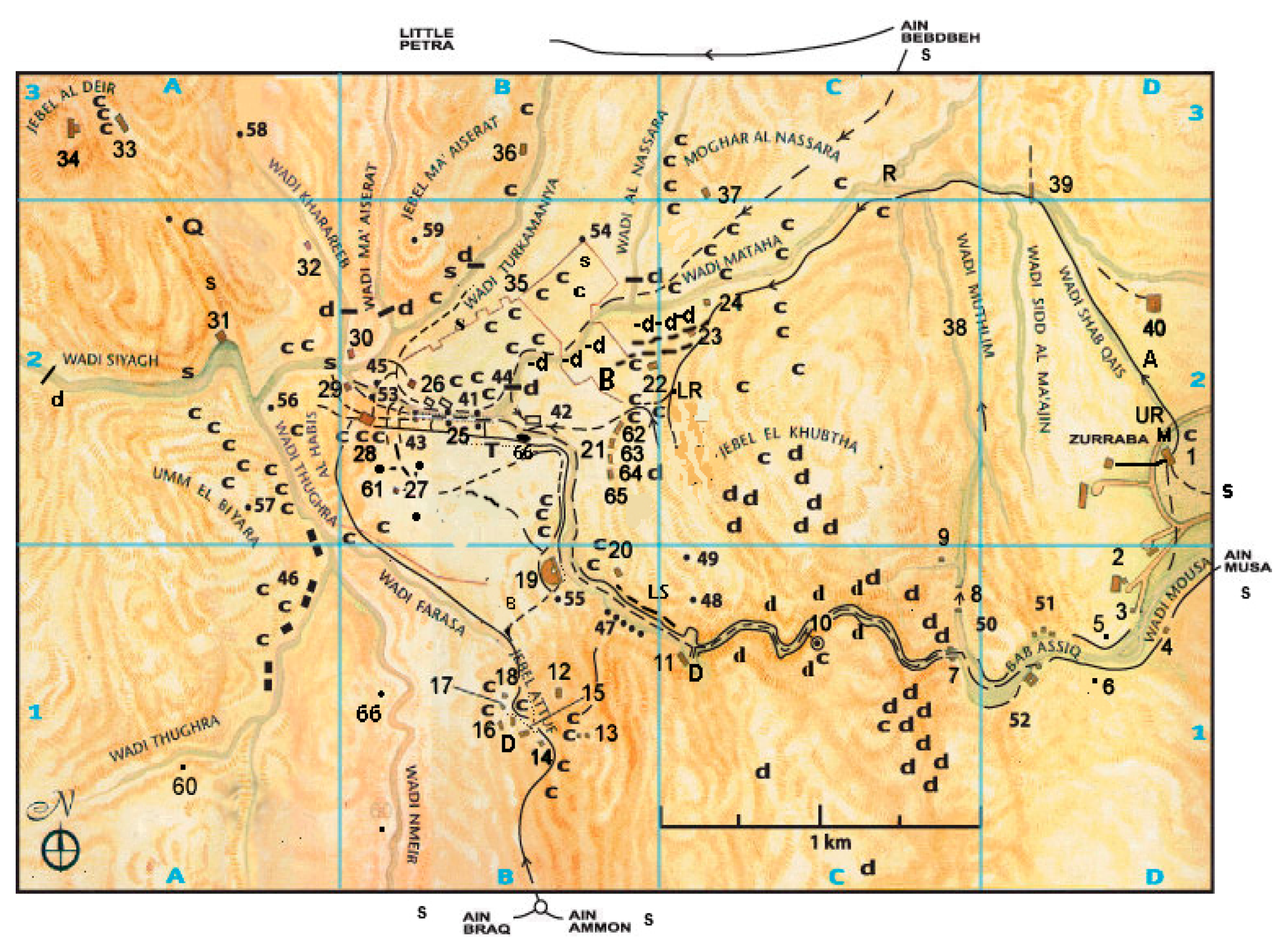
Figure 1 detail the known water supply and distribution pipeline systems leading water into the city’s urban core. Numbered locations denote major site features listed in the
Appendix A. Shown are major and minor catchment dams and multilevel stepped dams (-d, d, D), cisterns (c), water distribution tanks (T), and springs (s). The (-d) dams located across streambeds are stone barrier structures built to hold large quantities of rainfall runoff water for redistribution to urban structures and local agricultural areas. Dams denoted (d) are minor catchment structures that stored water in mountainous areas to limit descent and flooding of Petra’s low altitude urban center and have channels leading water to cisterns. Solid lines represent original pipeline paths originating from distant springs which in many cases now show only barren channels that once contained interlocked terracotta piping elements. The superimposed grid system (A, B, C; 1, 2, 3) defines 1.0-km
2 grid boxes to enable the location of numbered
Appendix A features.
Figure 1 represents the present state of knowledge of the location of pipeline structures from personal field exploration and survey results from previous site explorers [
7,
8,
9,
10,
11,
12,
13,
14,
15,
16,
18,
21]. Due to erosion and soil deposition landscape degradations over ~2000 years, as well as reuse and pillaging of piping elements by later inhabitants of the area, many terracotta pipeline sections are now missing from their original holding channels, obscured by subterranean placement, or are yet to be discovered. Extrapolation of pipeline continuance between available visible pipeline segments then represents the pipeline paths shown in
Figure 1 and is, at best, a first approximation to the entirety of the total pipeline system as much of the site remains unexcavated and subject to landscape change from millennia of soil erosion and deposition events caused by flood episodes, landslide events, and frequent earthquakes. Further hidden subterranean pipelines buried for defensive security purposes may exist to supplement the known pipelines shown in
Figure 1. Recent on-site discoveries appear to add new information in this regard: For example, Site 66 in
Figure 1 represents a large newly discovered (in 2016) platform with a centrally located temple structure yet to be excavated to determine its role in Petra’s administrative and ceremonial life [
28]. The water supply system serving this newly discovered complex remains to be discovered but surely exists given that all ceremonial structures presently known are accompanied by elaborate water systems for both aesthetic display and supply of potable water.
Additionally, as elements of major pipelines were intentionally built subterranean and as yet undiscovered due to limited excavations performed in the urban center and distant reaches of Petra,
Figure 1 can be considered a first approximation of the total piping network. Some major monuments located at high altitude exclude the possibility of canal water supplies from springs located at lower levels; in this case, channels directing rainfall capture to cisterns located nearby provided the water supply to high-level sites.
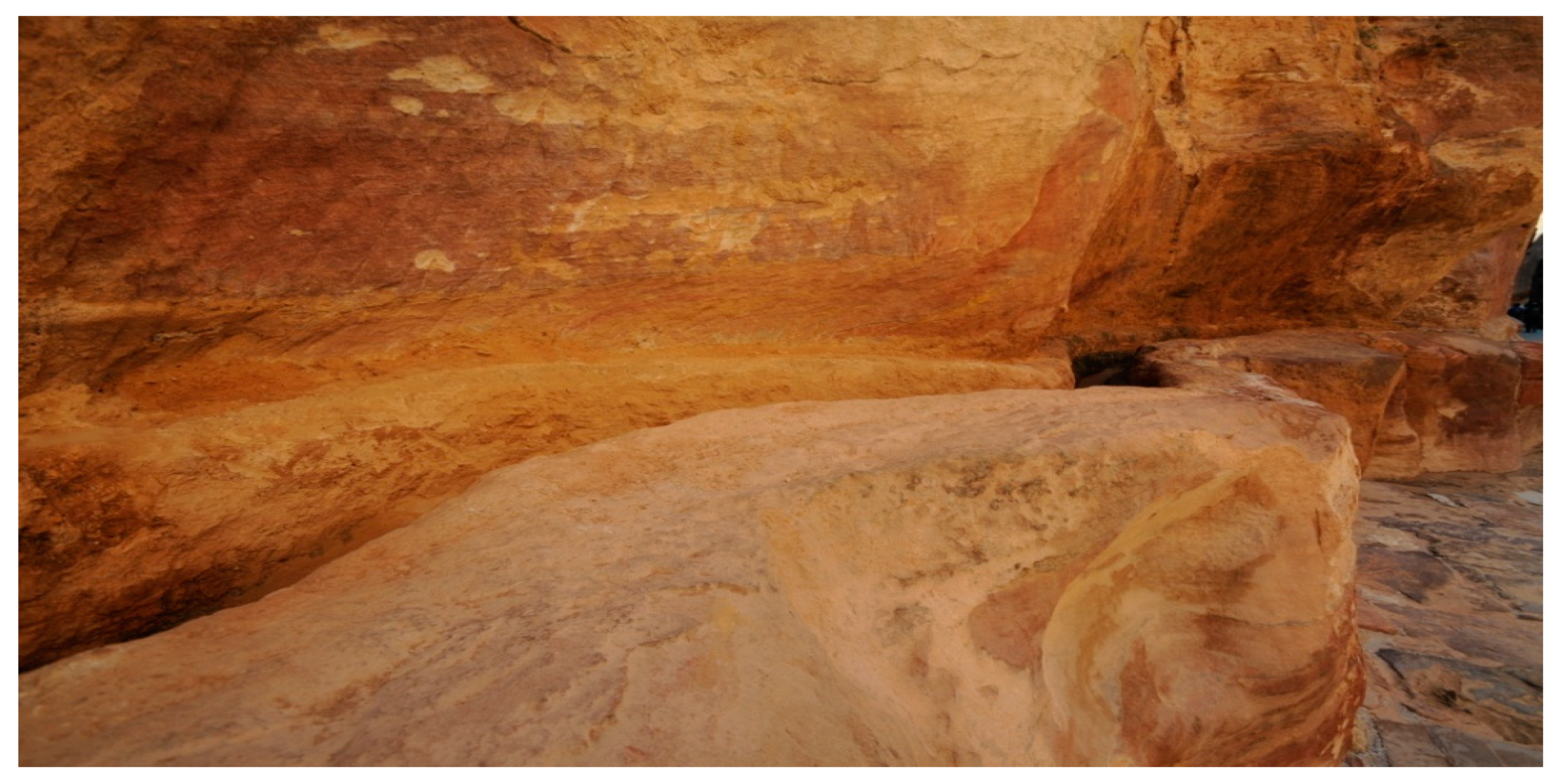
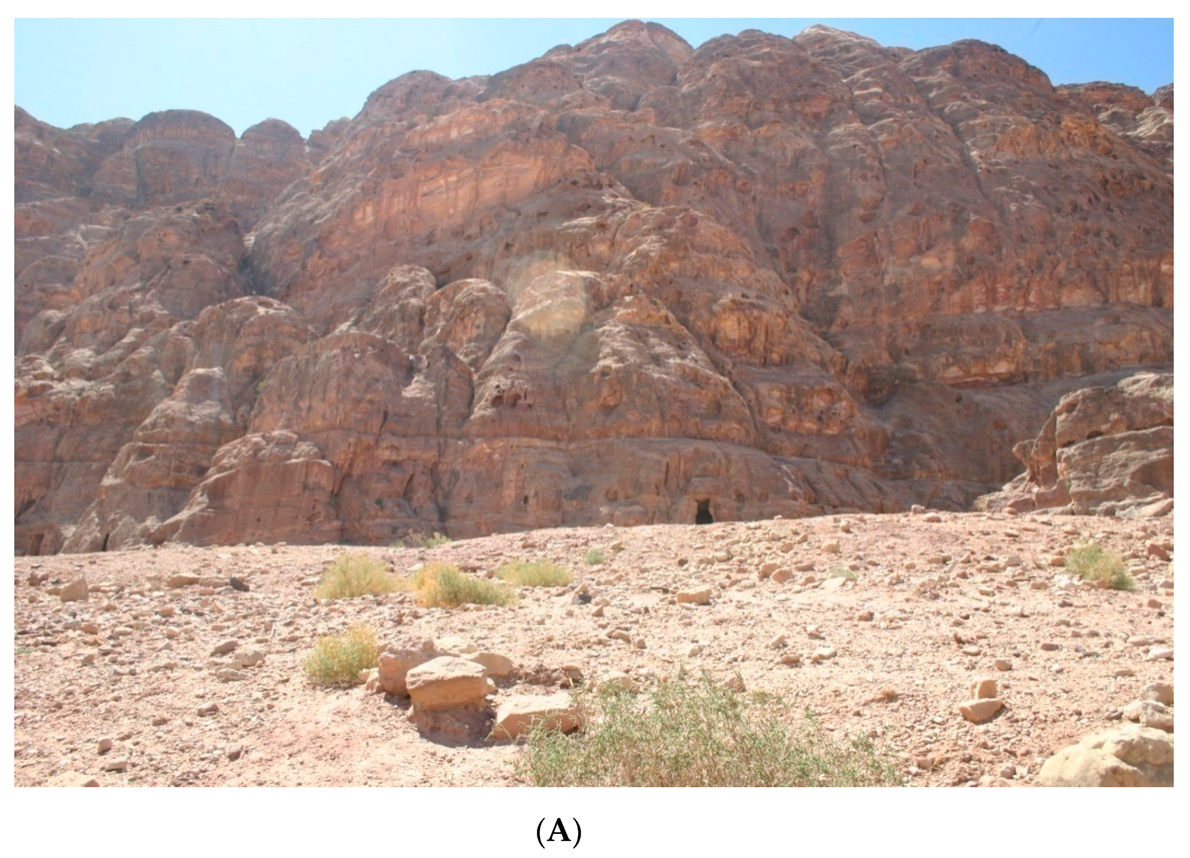
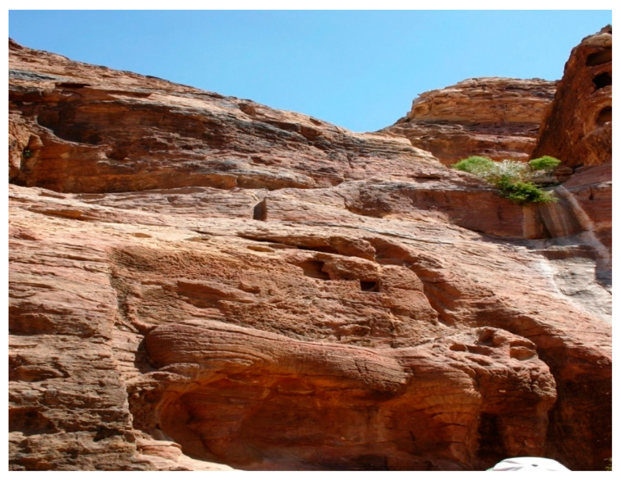
Petra’s urban core lies in a valley surrounded by rugged mountainous terrain.
Figure 2 demonstrates a section of the mountain terrain behind the ~10 m-high Q’asar al Bint temple (Feature 29,
Appendix A) located at the base of the Jebel al Deir mountain and gives a perspective on the rugged mountainous terrain encompassing the urban core of Petra. Seasonal rainfall runoff passes into the valley through many streambeds and was drained out primarily through the Wadi Siyagh streambed in antiquity (
Figure 1, A-2). Although present measurement of the Wadi Siyagh streambed slopes now precludes drainage resulting from water-transferred sediment deposits over millennia, this path was the main drainage channel during the city’s existence. Water flow into the city [
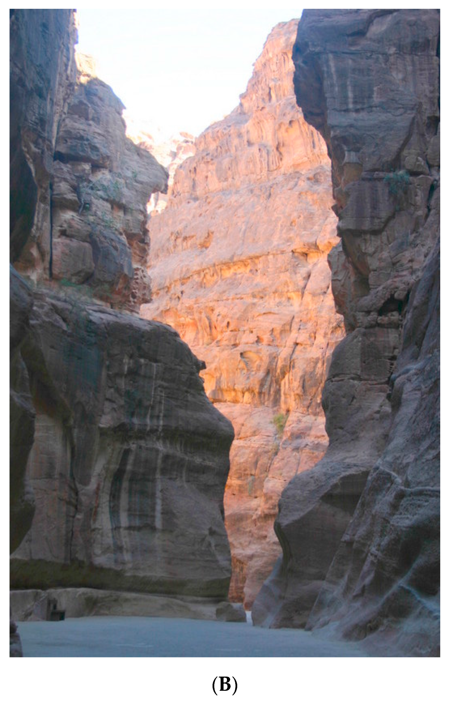
10] originated from captured rainfall runoff into cisterns from Wadi al Hay to the north, Wadi al Hudayb to the south, and from the watershed area supplying runoff into the Wadi Mousa streambed. Surface flows from these sources passed through the Siq (
Figure 1, D-1 to C-1;
Appendix A Feature 10) which is the ~2 km long narrow entry passageway into the urban center of Petra (
Figure 1 and
Figure 2A). The Siq is a natural, narrow passageway through the Jebel el Khubtha mountain range, varying from 5 to 10 m in width; the north and south walls of the Siq are near vertical with maximum heights up to 80 m.
By construction of a diversion dam and tunnel shown in
Figure 3 (
Figure 1; Feature 8 in
Appendix A) in the first century AD, flood water from the Wadi Mousa River was deflected from the Siq entrance and led to Wadi Mataha (
Figure 1, C-2, 3) that linked up with the section of the Wadi Mousa streambed within the city center; water then drained into Wadi Siyagh (
Figure 1, A-2) through a channel passing through the city center. This dam and tunnel construction served to divert the silt-laden floodwater away from entry into the Siq that would compromise the structural integrity of many of the monuments within Petra’s urban core region. At present, the Wadi Siyagh drainage path is partially blocked from silt deposits, causing flooding of Petra’s urban center during the rainy season. As the chemical composition of Petra’s stone monuments contain different salt varieties [
31], exposure to flood water causes destructive flaking from monument walls; this effect is apparent from observation of many of Petra’s urban sector monuments. Runoff water from the southern sector Wadi Thughra, Nmeir, Farasa, and northern sector Wadi Kharareeb, Ma’aiserat, and Turkamanya gullies (
Figure 1) additionally drained rainfall runoff into the Wadi Siyagh away from the city center [
10]. In sector B-2 of
Figure 1, a local depressed low area lies between the Jebel el Khubtha Mountain and sites to the west. Currently, a modern bridge crosses over the southern narrow end of this area. If the southern narrow drainage end of this basin was dammed in antiquity, rain water or a Wadi Mataha diversion channel could produce an internal shallow lake within city confines that would serve local gardening, nearby ceramic and metal working workshop areas as well as city aesthetic beautification purposes consistent with Nabataean plans to utilize all available water before disposal into the Wadi Siyagh drainage. As mentioned in Strabo ([
32]), “… the inside parts (of Petra) having springs both for domestic purposes and for watering gardens…”, which would be consistent with an internal shallow lake within city precincts whose borders and groundwater could serve as gardening areas and for specialty crops. At this stage of research, this feature awaits verification for its existence in ancient times.
Spring-fed water supply to the city before the first century BC was through a slab-covered, open channel dug into the floor of the Siq, conducting water from the distant Ain Mousa spring into the urban center of the city. A trace of this system in the vicinity of the south Nymphaeum along Colonnade Street may exist from GPS data [
33]. This channel perhaps extended as far as the Temenos Gate (
Figure 1, B-2; Feature 43 in
Appendix A) later built in early Roman occupation times past AD 106 to honor the visit of Hadrian in 131 AD. First century BC and first century AD Nabataean builders replaced this early Siq channel water supply system with a pipeline system along the north wall of the Siq supplied by a ~14-km pipeline carrying water from the Ain Mousa spring. Details of most of this pipeline system from the Ain Mousa spring are largely unknown due to later urban construction overlay except for a pipeline segment before the Siq entrance. First century BC and early century AD construction revealed a more integrated approach to site water system management as demonstrated by new and novel features. The major Siq northern wall channel supporting a pipeline (
Figure 4) was an additional feature eliminating earlier use of the Siq floor channel (
Figure 1; B-C-D-1 sectors). New features included surface cisterns to capture rainfall runoff, deep underground cisterns (one located in the eastern part of the site,
Appendix A Feature 28,
Figure 1), multiple pipeline systems sourced by different springs and storage reservoirs, floodwater control through diversion dams and tunnels, and pipeline supply system redundancy to ensure water delivery from multiple spring and high-level reservoirs—notably the massive Zurraba reservoir that supplied lower level smaller distribution and water storage reservoirs such as the M reservoir (
Figure 1, D-2 and
Figure 5B. The
Figure 5B M reservoir no longer exists due to construction expansion of the nearby town and may have been one of several other distribution reservoirs sourced by networks of canals from the Wadi Mousa spring.
Figure 5A,
Appendix A Feature 1, shows the high-level Zurraba reservoir supplied by a branch channel from the Ain Mousa spring that supplied water to high population concentration parts of the city. This reservoir also served as a drought remediation measure and served to provide large water supply storage and delivery for large caravan arrivals into the city. The lower level M reservoir (
Figure 5B,
Figure 1, 2-D) was connected to the upper level Zurraba reservoir through a pipeline; this lower reservoir provided water for occupation zones close to the Siq entrance. Due to modern road building and urban construction obliterating many of the ancient pipeline connections between reservoirs, the totality of the reservoir network pipeline system sourced by the Wadi Mousa spring remains to be determined.
Major pipelines, primarily on the north wall of the Siq, provided sediment particle filtration and removal basins (
Figure 6) and served a sophisticated hydraulic function particular to partial pipeline flow as described in detail in a later section. The Siq south-side water open channel, perhaps sourced by a south-side spring, likely served as the water supply for camels and horses accompanying personnel passing through the Siq. The north-side Siq pipeline had four open basins supplying potable water for personal use (typical of
Figure 6); this feature was an integral part of the hydraulic design of the pipeline as discussed in detail in a later section.
The new hydraulic features developed at later times reflected the need to bring high-quality potable water into the city center and serve city hillside occupation zones above the valley floor. Late first century BC and early first century AD developments demonstrated continual evolution of the Petra water system and reflected application of acquired technologies from exterior sources integrated with indigenous hydraulic engineering innovations to respond to the water needs of the city as a sustainable population center. Contingency water needs resulting from caravan arrival and water restocking anticipating transit to distant cities in North Africa and Mediterranean cities were vital considerations to maintain Petra’s importance as a vital trade emporium. Beyond serving as a transit center for foreign goods to distant areas through known trade routes, the Nabataeans had a monopoly on incense trade originating from Southern Arabia—a vital and profitable product that the ancient world valued for ceremonial functions.
In summary, the means to capture and store a fraction of rainfall runoff through dams and cisterns, to build flood control systems, and build pipelines and channels to deliver water from distant springs to provide a constant water supply to the city was vital to understand Nabataean contributions to hydraulic engineering and water management practice. While water storage was vital to the city’s survival, springs internal and external to the city (Ain Mousa, Ain Umm Sar’ab, Ain Braq, Ain Dibdiba, Ain Ammon, Ain Beidha, and Ain Dibidbeh) supplied water channeled and/or piped into the city to provide the main water supply (
Figure 1). Several spring-supplied reservoirs exterior to the city (M–Zurraba,
Figure 5A,B) provided additional water storage reserves. No accounts of other lower level, near city reservoirs exist at present due to modern urban construction; thus the complete reservoir water storage system remains unknown. Additional on-demand use of reservoir water for industrial ceramic and metal working workshop areas located at the base of the Jebel el Khubtha Mountain and for ceremonial use to supply triclinium rituals for tomb celebratory functions are indicated in [
4,
10,
12]. Of the many springs used in antiquity, the Wadi Siyagh spring near the quarry (
Figure 1,
Appendix A Feature 31) remains functional for local inhabitants living in remote sections of the ancient city together with the Ain Mousa spring which now provides water for the modern town of Wadi Mousa and the water display structure in the town center. Water taken from the open channel within this structure has ritual use as evidenced by members of holy sects collecting water in containers for ceremonial functions.
3. Details of the Siq Pipeline System
The main city water supply of ancient Petra originated from the Ain Mousa spring about 7 km east of the town of Wadi Mousa (
Figure 1, D-1), combined with the waters from the minor Ain Umm Sar’ab spring. The flood bypass tunnel (
Figure 3,
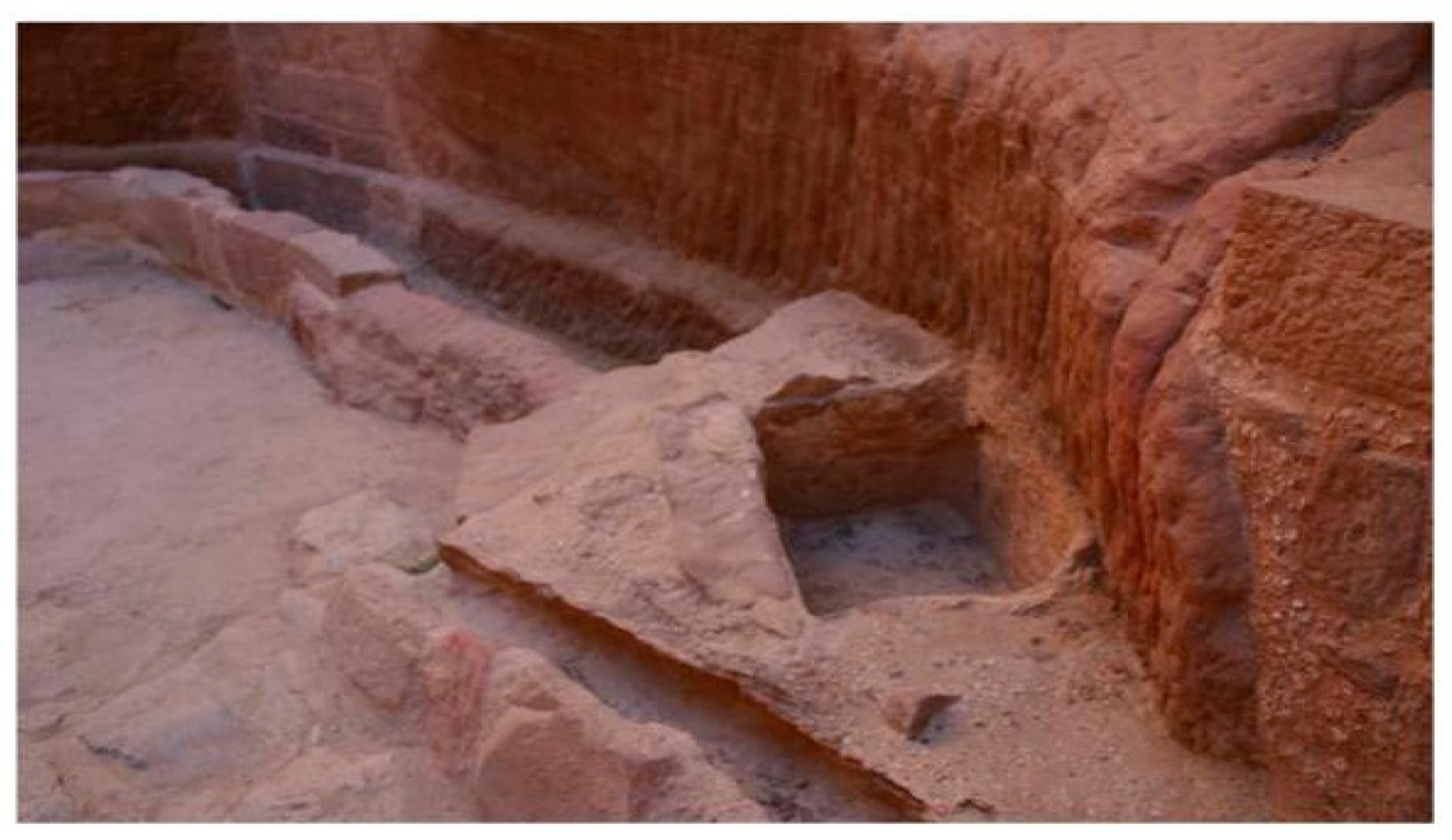
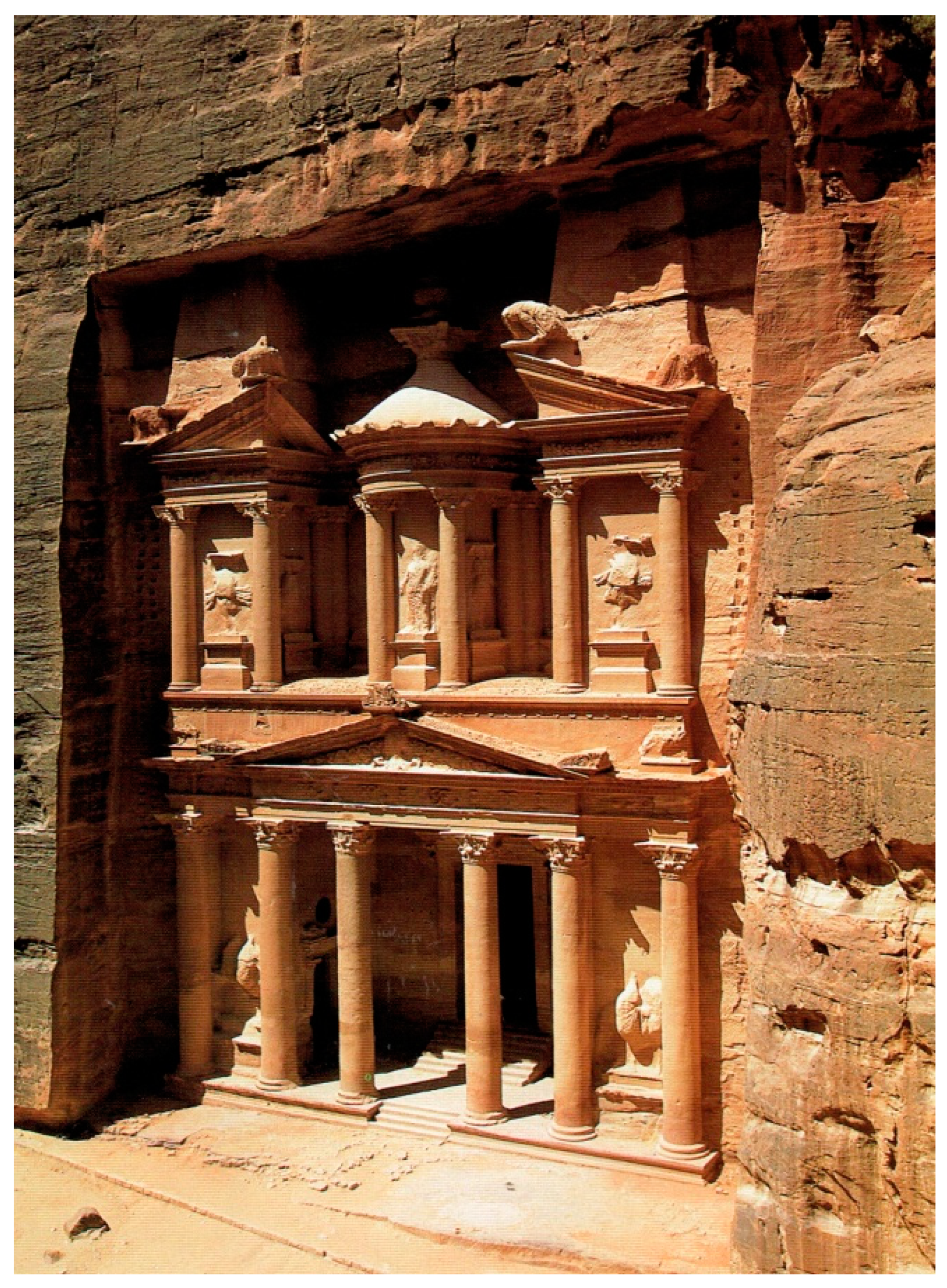
Appendix A Feature 8) at the Siq entrance, together with an entry dam and elevated paving of the Siq floor, reduced flooding into the urban center from rainy season runoff into the Wadi Mousa River. Part of the early slab-covered channel water supply to the urban core of Petra now lies under hexagon slab pavement in front of the Treasury construction attributed to Aretas IV (9 BC–AD 40). Recent excavations of this area revealed an empty tomb structure below the front part of the Treasury (
Figure 7), although the intended use remains conjectural.
Later construction of the early Nabataean Siq water channel was replaced by the Siq pipeline water supply system supplied from the Ain Mousa spring source. The four open surface water basins between Sig piping segments (Bellwald, principal Siq excavator, personal communication) typical of those shown in
Figure 6, give indication as to the hydraulic technology available to Nabataean water engineers as further discussion indicates. It is of note that in several locations along the ~2-km length of the Siq pipeline, top portions of the pipeline have been opened up, revealing heavy sinter deposits on pipeline bottoms that taper off about halfway up the pipeline side walls. This observation would indicate that a partial flow existed in at least some portions of the pipeline by observation of the sinter deposit patterns. If a partial flow in Siq pipeline sections was the original design intent of Nabataean water engineers, then opening up the top part of the pipelines made no difference in the pipeline flow rate and may have had the additional benefit of flow observance and access to cleaning sinter from pipeline inner surfaces. Additionally, if partial flow in the Siq pipeline was the design intent, then the Siq pipeline system was not full-flow pressurized as an air space existed over the partial flow, thus reducing the possibility of pressurized water leakage at pipeline joints. Details of the design intent of the Siq pipeline based upon these preliminary observations are next considered to proceed toward hydraulic analysis of the Siq pipeline and its Outer Siq continuation to the city center.
With increasing water needs for increasing population in early centuries AD, an elevated ~1-km long, north-side pipeline extension (
Figure 8; LS, Outer Siq,
Figure 1 1-B, C) extended the utility of the Siq pipeline system [
14,
15,
16,
25,
27] to supply potable water to further reaches of Petra’s urban core. This pipeline extension provided water supply to structures located in the
Figure 1 B-2 district, as well as providing pipeline water supply to the Nymphaeum (
Appendix A Feature 42,
Figure 1). Further pipelines emanating from the Nymphaeum to the Temple of the Winged Lions (
Figure 9), major tombs fronting the Wadi Mataha housing structures, and elite palace structures in early stages of excavation [
18,
19] existed, although details await further excavation. Continuance of water flow through a pipeline to a bridge across the Wadi Mataha led water to the south side of the site as further discussion details.
To fully analyze the design intent of the Siq pipeline, note first that within pipelines, destructive hydraulic instabilities may exist [
34]. These include transient pressure waves, flow intermittency, internal pipeline hydraulic jumps, transient turbulent drag amplification zones, partial vacuum regions, and subcritical to supercritical (and vice versa) flow transitions—these instabilities largely depend upon pipeline slope and internal pipeline wall roughness—all of which affect flow stability and pipeline flow rate. Such hydraulic problems affecting the design of pipeline systems required development of advanced technologies to produce stable pipeline flows that matched a sizeable fraction of the Ain Mousa spring source input. The total pipeline design from the Ain Mouse spring source to the Siq and through the Outer Siq needed to be designed to produce the maximum flow rate the total pipeline system could sustain. Further design considerations involved limiting full flow conditions within pipelines (pipeline cross-section fully occupied by water) to limit hydrostatic pressure within a pipeline. This design consideration limited leakage at the thousands of terracotta pipe-joint-connections along long lengths of pipelines. For a typical pipe element length of ~0.35 m and total pipeline length over ~14 km from the Ain Mousa spring origin location to the end of the Siq and Outer Siq pipeline with a total height drop well over ~50 m (data derived from the contour
Map of Petra), high hydrostatic pressure in a full flow pipeline would increase the likelihood of pipeline element connection joint leakage at~42,000 pipeline joint connections. Solutions to mitigate many of the design and operational problems provide insight into Nabataean water management expertise.
CFD calculation [
30] of full-flow volumetric flow rates in 14 cm diameter(D) piping were made for internal wall roughness ε/D > 0.01 (where ε is the mean-square internal pipeline roughness height); this ε/D value holds for roughness typical of terracotta internal pipeline walls, demonstrating casting corrugations and erosion usage pitting [
35] for typical Reynolds number Re ~10
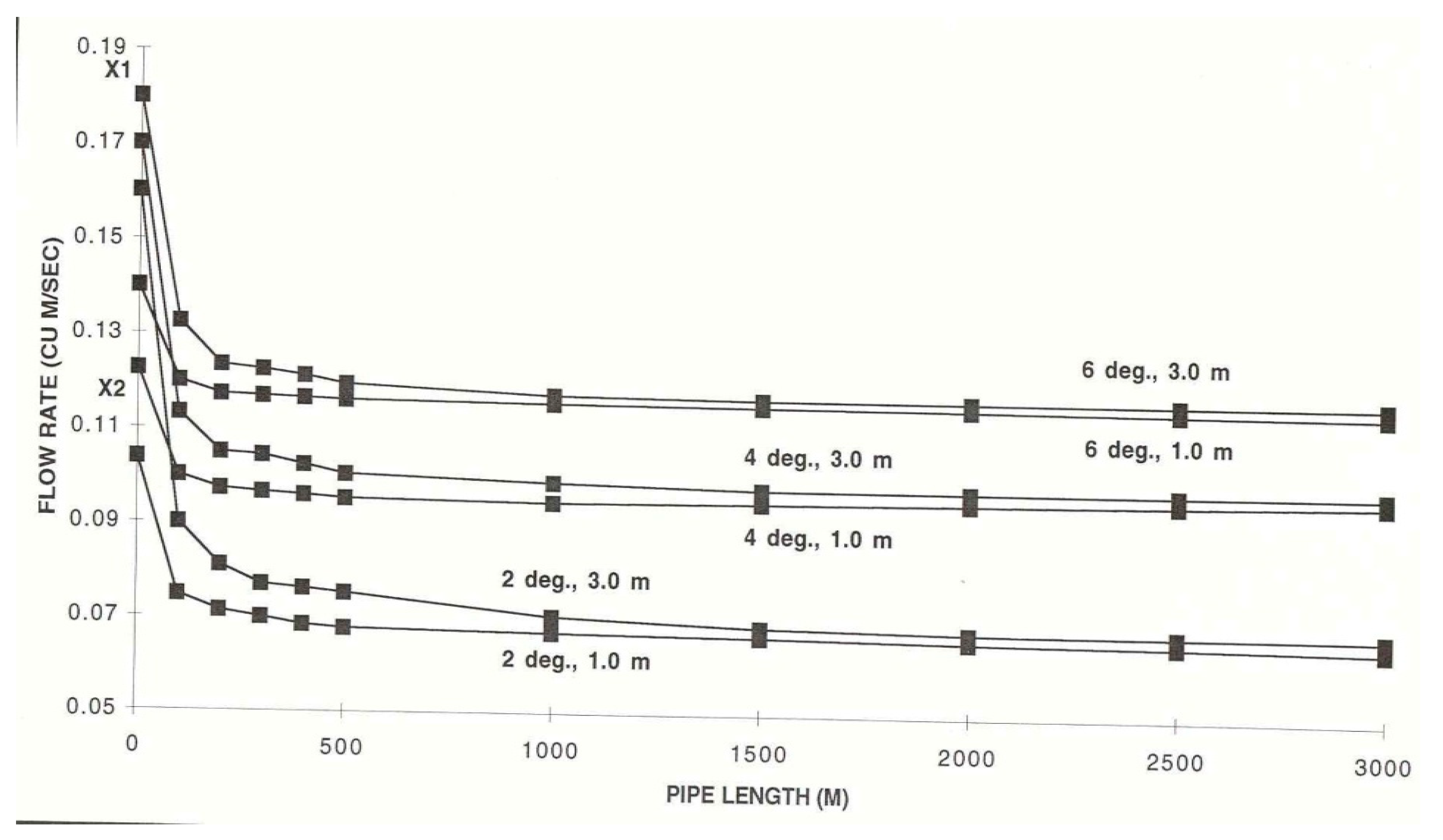
5 values. For pipelines at 2-, 4-, and 6-degree declination slopes for 1.0 and 3.0 m supply head,
Figure 10 reveals that past ~400 m pipeline length, an increase of input head does not substantially increase the flow rate [
17]. Past this length range, even a 3× head increase does not substantially increase flow rate. The implication for the ~14-km long Ain Mousa spring-supplied pipeline to the Siq and Outer Siq extension is that sophisticated hydraulic engineering had to be in place to match the estimated [
12,
13] maximum Ain Mousa spring output of~1000–4000 m
3/day; (~0.01–0.04 m
3/s) through the Siq pipeline without invoking any of the flow instability problems previously alluded to. Flow transmitted through the Siq pipeline at the maximum Ain Mousa output flow rate clearly required knowledge of flow conditions in the pipeline before the Siq entrance (which is likely full flow due to internal pipeline wall roughness flow resistance considerations and low pipeline slope) coupled with knowledge of Siq and Outer Siq pipeline designs that mitigate flow resistance and flow instabilities that would propagate upstream into the subcritical supply flow pipeline.
The internal pipeline flow rates shown in
Figure 10 are based upon a low pipeline wall roughness of ε/D ~0.01; higher ε/D ~0.07 values that account for pipe element connection socket roughness reduce flow rates substantially, leading to
Figure 10 curves being shifted downward by a factor of ~3 for typical Re ~10
5 Reynolds number values. On this basis, the observed Siq rough internal wall pipeline at a 2-degree slope permitted a 0.023 m
3/s flow rate and, at a one-degree pipeline slope, permitted a 0.017 m
3/s flow rate corresponding to ~1.5 and ~1.1 m/s mean velocity in the 14-cm internal diameter pipeline with corresponding flow rates of ~80 (0.02 m
3/s) and ~60 m
3/h (~0.02 m
3/s) compared to the Ain Mousa flow rate of 0.01 to 0.04 m
3/s. Thus, even high head values from the Ain Mousa spring to the Siq entrance pipeline had little effect of increasing the flow rate given the long 14-km supply pipeline as
Figure 10 implies. The additional ~2-km Outer Siq pipeline lengths to the 14-km Ain Mousa spring to Siq exit length added additional flow resistance due to additional pipeline internal wall roughness resistance; all these elements had to be considered for a substantial fraction of the Ain Mousa spring flow rate to enter the total pipeline length under maximum flow rate conditions without instabilities and leakage problems. For lower flow rate conditions due to Ain Mousa spring seasonal rainfall absorbance conditions, only a trickle flow would go through the Siq pipeline, emphasizing the need for available storage reservoir water supplements to maintain potable water supply for the city’s ~20,000 population and caravan trade. Any excess flow beyond the Siq extraction flow rate from the Ain Mousa spring was likely used to recharge upper and lower level reservoir systems for on-demand water usage. Here, normal flow to the Siq may have been temporarily stopped to serve lower reservoir filling—this being done by pipeline blockage—and for upper reservoir filling, pipelines from the Ain Musa spring likely served this purpose. Given the ~10,000 m
3 capacity of the main Zurraba reservoir (
Figure 5A) and that of several additional minor reservoirs, the additional Ain Mousa flow rate capacity not used for the total Siq pipeline system served to provide additional reservoir water storage for on-demand and drought remediation use as well as for pipeline maintenance shut-offs where alternate pipeline water supplies were available from reservoirs. In summary, to this point it appears that a sizeable fraction of the Ain Musa spring flow rate could be transmitted through the Siq pipeline with provision for system shut-off to refill lower reservoirs for drought condition water availability, caravan water supply, and pipeline maintenance; however, there is more to this story to demonstrate the engineering that this water system contains.
Along the Siq north-side pipeline, several typical open basin features (
Figure 6) are found at intervals along the pipeline. Each basin permits an accumulation of water serving as a head tank for its downstream piping length segment.
Figure 10 reveals that hydrostatic head substantially influences flow rate for pipeline lengths less than ~500-m, and more so for shorter pipeline lengths. The head is reset at the origin of each of the piping lengths between basins so that flow through each piping segment is only sensitive to its local head tank head value. This modification led to partial flow (pipeline cross-section partially occupied by water) in Siq pipeline segments reducing overall flow resistance. As pipeline flow extending ~14 km from the Ain Mousa spring to the Siq entry point was mostly subcritical full-flow due to the high pipeline internal wall roughness flow resistance and low slope, the lowered resistance of Siq pipeline segments at ~3-degree hydraulically steep slopes between basins induced partial flow in distal portions of the ~14-km Ain Mousa spring supply pipeline to the Siq pipeline. The slightly lowered flow resistance could help to raise the overall system flow rate due to lowered back pressure and partial flow frictional wall resistance decrease. In simpler terms, lowering the frictional flow resistance in the end regions of a pipeline permitted a higher flow rate to be achieved through the entire pipeline system.
The four Siq north-side open basins (Bellwald, Siq principal excavator, personal communication) additionally served to provide drinking water along the Siq narrow passageway (
Figure 2A) and access for cleaning of silt particles entrained in the flow to enhance potable water quality. Atmospheric pressure in the air space above the partial flow water surface in the Siq pipeline segments reduced pipeline joint leakage as would occur under a pressurized, full-flow condition design. To achieve a piping design based on a 14-cm pipe inner diameter at the declination angle of the Siq, ideally partial, critical flow at unit Froude number (Fr = 1) at critical depth (y
c/D~0.8–0.9) would provide the maximum flow rate the piping could convey. As open basins were sequentially lower than their predecessor upstream basins due to the declination slope of the Siq pipeline, each basin water height supplied head for its adjoining downstream piping section. Thus, partial flow existed throughout most of the Siq piping sections where flow entering a ~3-degree slope pipe section from a basin transitioned to a partial-flow, critical depth. This result indicates that the Froude number for the Siq pipeline flow is on the order of unity at close to the permissible ~96 m
3/hr flow rate. As the main purpose of the Siq water supply system was for the maximum flow rate to the urban center, any flow resistance changes that would increase flow rate were part of Nabataean water engineers’ design intent. This was apparently achieved to gain a larger portion of the Ain Mousa flow rate to be used to supply the urban center’s water needs. The thick sinter build-up in the (now visible) open bottom-most part of Siq piping supports the deposition pattern resulting from partial flow conditions existing in the Siq pipeline segments.
In the area immediately west of the Treasury, the Outer Siq pipeline (
Figure 1, LS, B, C, and
Figure 8) continued the Siq pipeline and was set at a slightly lower angle than the supply Siq pipeline. Given the Siq pipeline flow rate, a further consideration arises as to the stability of the flow in piping sections within the Siq as well as for water arriving to the Nymphaeum (
Figure 1,
Appendix A Feature 42) through the further Outer Siq pipeline extension subject to the input Siq flow rate. Any flow resistance from the Outer Siq pipeline extension would have a small effect on the upstream flow rate given the near-critical flow rate sections in the Siq pipeline that limit upstream influence. For water delivery from the Outer Siq portion of the total pipeline, if water delivery was pulsating into open basins within the Nymphaeum, then spillage and sloshing occurs amplifying flow instabilities that would compromise the aesthetic display of fountains and open pools in the Nymphaeum and induce forces within adjoining distribution pipelines promoting joint separation and leakage. For an examination of flow stability within the Outer Siq pipeline extension, CFD models were made for a ~1220-m section of the piping extension with a higher declination slope than that in the Siq pipeline; this length represents the approximate distance from the exit of the Siq pipeline to the Nymphaeum (Feature 42,
Figure 1). Previous research [
10] has indicated a further south-side Nymphaeum structure across the Wadi Mousa streambed serving the marketplace area with an extension of the south arm of the Siq pipeline; traces of elevated reservoirs providing pressurized water to the south Nymphaeum are described in [
25].
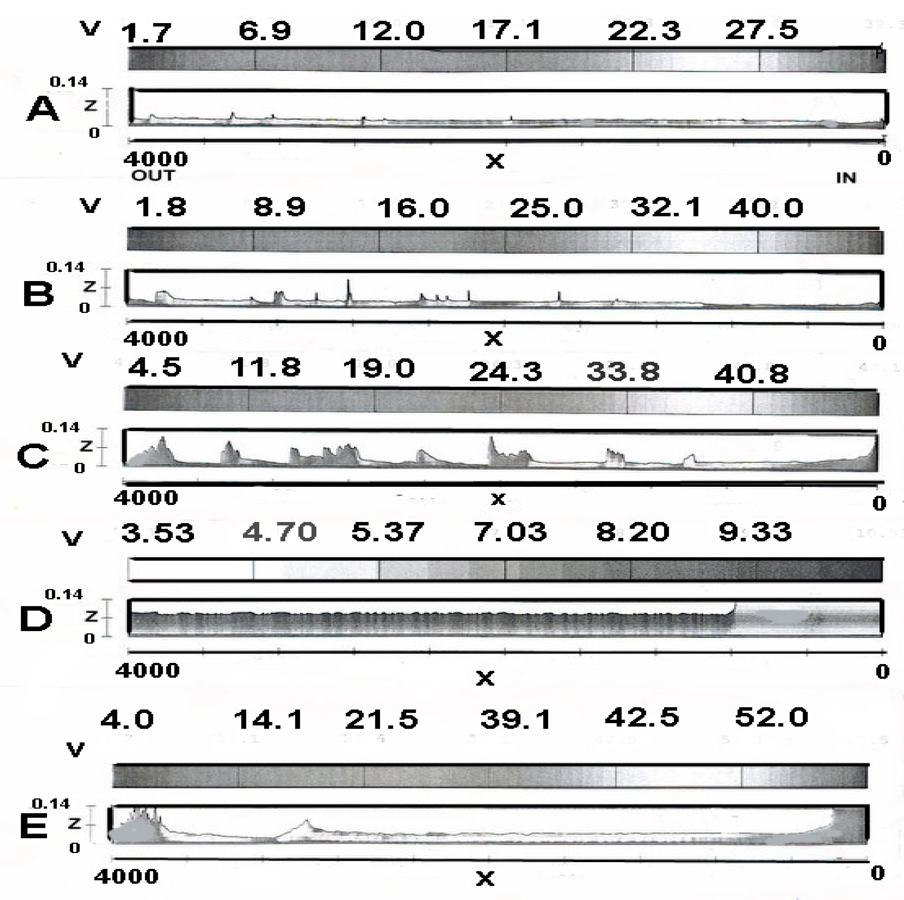
FLOW-3D computer solutions (
Figure 11) for 0.305(A), 0.610(B), 1.54(C), and 3.05(E) m/s water velocities were made with observed ε/D values typical of the interior surface of piping elements at the higher declination slope of the Outer Siq segment; here water velocity is expected to be higher than in the supply Siq pipeline.
Figure 11(D) results are for a smooth interior pipe element wall at 1.54 m/s velocity to demonstrate the effect of wall roughness on flow patterns at the same water velocity as 1.54 m/s (C). For an illustrative example, water at ~96 m
3/hr was accepted into the Outer Siq piping—average pipeline water velocity was then ~1.73 m/s. Given the flow was slightly supercritical at this velocity, the flow approximated critical depth for Cases (B), (C), and (D). For flows close to critical, the normal depth was close to the critical depth [
35]. As partial flow existed in the extension section (similar to that in the Siq piping) and had approximately the ~96 m
3/h flow rate at about the steeper declination angle as the Siq piping, near critical flow conditions existed throughout the Outer Siq extension pipeline.
Figure 11 shows the transition to lower water depths from the entry boundary condition for all supercritical (B), (C), (E) and (D) cases, primarily due to the steeper declination angle. For the subcritical Case (A), water was at a low level due to low flow velocity.
Figure 11, Case (B) at ~1.2 m/s approximated the flow effect at a mean velocity of ~1.75 m/s and indicated that only minor, random height excursions occurred in water flowing within the Outer Siq pipeline—this indicated that the water supply system through the Outer Siq extension to the Nymphaeum was stable, which was advantageous for proper operation of the Nymphaeum water display system. At twice this velocity,
Figure 11(C) indicates large height fluctuations in the water surface, indicating unstable flow delivery occurring in the pipeline system. This indicates that the flow rate selected from the Ain Mousa spring by Nabataean engineers was a deliberate design choice to achieve stable flow in the total system. For Case (E), the high flow rate case shows susceptibility to a hydraulic jump creation due to the amplified supercritical flow interaction with pipeline internal roughness. This case serves as limit on the declination angle that could be implemented by Nabataean engineers. Here Cases (A) and (B) likely serve to give the declination angle of the Outer Siq extension pipeline due to the small flow disturbances indicated; Cases (C) to (E) would require a mandatory settling basin design to ensure smooth flow on to city center locations. Such an intermediate settling basin was observed in practice most likely to smooth the passage pipeline flow on to the city center and Nympheaum indicating a safety measure to ensure smooth flow for any of the Cases shown for any of the different declination angles shown that supported higher flow rates.
Comparison of
Figure 11, Cases (C) and (D) indicates that internal pipeline wall roughness amplified large-scale turbulent eddies that contributed to flow unsteadiness; this effect was included in the Case (B) result. Tracking the distal end of the Outer Siq extension pipeline revealed it was intercepted by a head reset open basin, indicating a further feature to ensure flow stability for flow continuing onto further pipeline branches and the Nymphaeum.
In summary, the total Siq system was designed to optimally transfer close to the Ain Mousa spring output flow rate of ~96 m3/hr with partial flow conditions in several pipeline segments. This design largely eliminated large hydrostatic pressure conditions associated with full flow designs that would cause pipeline joint leakage at high hydrostatic pressures. Additionally, open basins along the Siq pipeline permitted removal of sediment debris that would ultimately clog the Siq system and destroy its functioning. In total, the various hydraulic flow regimes designed into the Siq pipeline (Fr < 1 subcritical, Fr > 1 supercritical, and Fr = 1 critical) and its Outer Siq extension necessary to capture a large fraction of the Ain Mousa spring output flow rate indicates an advanced knowledge of hydraulic science.
4. The Wadi Mataha Pipeline System
The water supply systems of Petra employed springs (s,
Figure 1) both within (Ain Siyagh) and outside city limits (Ain Dibidbeh, Ain Mousa, Ain Braq, and Ain Ammon) to bring water to city monuments through pipelines. Reservoirs fed by the Ain Mousa (M–Zurraba,
Figure 1) as well as other springs and reservoirs (no longer in existence due to modern urban expansion) provided supplemental water on-demand for arriving caravans or other utilitarian purposes. Pipelines composed of short interlocking terracotta pipeline elements, with sealed at joint connections by hydraulic cement, were typical of pipeline construction. Nabataean pipe elements were typically ~0.35-m long with an inner diameter range of ~14 to 23 cm, as observed from sample pipeline sections on display at the Petra on-site museum. As technologies developed over centuries, many different pipeline types developed with improved features to reduce internal pipeline wall frictional resistance. One special design of Nabataean tailored internal wall roughness minimized drag resistance ([
25], pp. 268–271) according to modern hydraulic engineering theory and laboratory tests—if intentional from early observations and tests, this hydraulic science development occurred some ~2000 years before its “official” discovery in western hydraulic science.
Later Roman modifications to existing Nabataean water systems in the Great Temple area [
20,
21] (
Figure 12) include small diameter lead piping and Roman standardized pipe diameter designs [
22] for Roman extensions of the marketplace and Cardo Street areas, as well as for the Paradeisos Pool areas. The Roman standards for what a city under its control should have (fountains, baths and other water display structures) were an inherent part of Roman reconstructions present in post-106 AD Petra together with standardized piping size elements and lead piping. Excavations in the Cardo area show standardized Roman pipelines grafted onto existing Nabataean pipelines originating from Siq pipeline extensions to this area that expanded the marketplace area with fountains. For the Wadi Mataha pipeline, construction details of the channel on the Jebel al Khubtha mountain face (C-2,
Figure 1 and
Figure 13, A–C) carry partial pipeline remains permitting analysis of its design and function.
The presence of pipeline segments, as opposed to an open channel conveying water (in the Wadi Mataha pipeline for example,
Figure 13, A–C), is evident by noting that flow accelerating on a hydraulically steep open channel encountering bends would form surface height excursions and hydraulic jumps, causing channel overflow. For an open channel design, only a trickle flow from the upper reservoir could be contained in the channel without spillage. As water conservation was a prime concern, open channel systems subject to evaporation and spillage were not considered viable compared to pipeline systems. Some outer slab-covered sections of the Wadi Mataha channel are evident from and typical of Nabataean methods to provide a defense against water heating from direct sunlight exposure. Additionally, by surrounding embedded pipelines in channels with stabilizing soil to limit pipeline motion caused by water frictional forces and flow instabilities, leakage could be reduced at pipeline connection joints.
Figure 10 governs admissible flow rates for full flow conditions such as would apply to pipeline flows originating from the M–Zurraba reservoir; for partial flow conditions as indicated in
Figure 11, theoretical means are available for flow rate estimates [
35,
36]. Note also that open channels carrying water from distant springs were not a design option due to evaporation loss of scarce water supplies.
The pipeline along the eastern face of Jebel al Khubtha originated from a pipeline branch originating from the M–Zurraba reservoir complex. Typical full flow maximum flow rate estimates from
Figure 10 are on the order of ~0.05 m
3/s, which would satisfy on-demand water supply requests; lesser flow rates would be possible by using a flow control valve originating from the reservoir. Piping from the high-level reservoir source proceeds to a lower reservoir elevated above the Sextus Florentinus Tomb area(
Appendix A Feature 22,
Figure 14), then proceeds southward toward the royal compound area [
19] (
Figure 15,
Figure 1, 2-C), then on to monumental royal tomb architecture (
Figure 15) near the Palace Tomb and a nearby fountain [
10], then further on to the Nymphaeum for further pipeline water distribution to other parts of the city together with multiple basin/reservoir areas created by multiple dams along the Wadi Mataha streambed (-d,
Figure 1).
This flow network provided water to cisterns associated with ceramic and metal workshop areas and for celebratory triclinium functions associated with monumental royal tomb structures (
Figure 1,
Appendix A 62, 63, 64, and 65;
B in region 2-B) and additionally made available upper reservoir water as a drought remediation measure. Recent research [
18,
19] indicates that several royal compounds exist (
Figure 15) in the terminal pipeline area supplied by the Wadi Mataha pipeline (
Figure 1,
B, region 2-C). In conjunction with water from the Outer Siq pipeline extension directed into this area, ample water supply to royal compounds, even in drought periods, was assured as royal compound water needs for both consumption and aesthetic water displays dictated. Pipeline connections to the multiple royal compounds await excavation, but given nearby multiple water sources from the Wadi Mataha and Ain Mousa springs through the Outer Siq pipeline extension, as well as the upper reservoir water supply, abundant water supplies from multiple sources would be available to serve multiple palace structures. Water continued by pipeline past the Nymphaeum southward to city center areas and ultimately was transferred by a pipeline across a bridge to the commercial marketplace and fountain area district to supplement Siq pipeline water to the marketplace area. Final water discharge from all pipeline sources was ultimately led to the Wadi Siyagh natural drainage path. The present-day bridge in the Q’asar al Bint area contains visible ancient pipeline elements remaining after modern modifications to the earlier Nabataean bridge; this pipeline permitted water to cross over the bridge to sites on the south-side marketplace, Great Temple (
Figure 12) and al Bint (
Figure 2A) areas. Multiple pipeline water supplies to the same site areas would permit pipeline cleaning outages given redundant water supplies from other parts of the city, as well as a pedestrian transit path across the Wadi Mataha streambed.
Given the slope (~2.8-degrees) and construction detail of the entire Wadi Mataha pipeline, the question arises as to the engineering behind the selection of a pipeline slope that would yield the maximum flow rate given a variety of possible design options. Given the necessity to construct an elevated basin carrying the pipeline on the near vertical face of the Jebel al Khubtha mountainside (
Figure 13, A–C) and the surveying required for the pipeline slope over a considerable length, a preliminary engineering analysis was necessary preceding construction. Analysis of alternate pipeline slope choices that have the potential to maximize the flow rate, while minimizing leakage from the many connecting joints between piping elements, was vital to a successful design. Details of flow patterns within the pipeline connecting the upper to the lower reservoir were analyzed by computer simulation to provide insight into the decision-making rationale underlying the Nabataean water engineers’ choice of the most efficient pipeline slope.
Starting from an elevation of ~910 masl (meters above sea level) near the Mughur al Mataha and Jebel al Mudhlim areas (
Figure 1, point
R), the pipeline on the face of Jebel al Khubtha extends ~1.5 km to the lower reservoir near, but offset and above, the Sextus Florentinus Tomb (
Figure 14) area located at ~770 masl. The upper water source is from the M–Zurraba reservoir connection supplied by a Wadi Mousa spring branch possibly augmented by a local spring. A ~15 m lower reservoir elevation above the tomb base at 770 masl yields an observed pipeline declination slope of ~2.8 degrees measured from the horizontal. While this slope was the ultimate choice of Nabataean hydraulic engineers, an alternate shallower slope choice of one-degree declination would require a yet higher elevation reservoir, requiring a high support base built onto the near-vertical Jebel el Khubtha mountainside. While this construction had the benefit of allowing the pipeline to extend further to the south to provide water to urban habitation areas, this design option was redundant given water supplies through the Siq and Outer Siq providing water to the same area of the city. For a one-degree declination slope option (slope measured from the horizontal origin point
R of the pipeline as it switches to the western face of the mountain as shown in
Figure 1), the elevation of the lower reservoir would be much higher above the ground surface, requiring an extensive base construction support. Beyond structural difficulties involved in this construction, computer modeling of water flow patterns in a long pipeline at one-degree declination slope revealed a problem. To expose this problem, a FLOW-3D CFD model (
Figure 16, Case A) consisted of a left-most upper reservoir connected to a lower right-most reservoir by a pipeline at a one-degree declination slope; CFD calculations qualitatively duplicated hydraulic phenomena present in the pipeline flow from the upper reservoir
UR to the lower reservoir
LR.
Figure 16, Case A results demonstrated the pipeline cross-section was fully occupied by water (full flow) given the submerged pipeline exit condition into the lower reservoir. A design with the pipeline exit above the lower reservoir water level would still support mostly full-flow conditions over most of its length, but be subject to ingested air slugs moving counter to the flow direction ingested at the pipeline exit, causing unstable flow conditions [
34]. A volumetric flow rate of ~0.05 m
3/s entered the pipeline from the upper reservoir; this was the permissible full-flow rate for ε/D ~0.1 pipeline internal roughness over long pipeline distances (
Figure 10) at a one-degree declination slope. Increasing the upper reservoir head did not result in a proportionate increase in volumetric flow rate for long pipelines over 400–500 m length as indicated by
Figure 10. CFD results for
Figure 16, Case A indicated full-flow for a submerged outlet pipeline under high hydrostatic pressure near the end reaches of the pipeline—this increased the likelihood of pipeline joint leakage due to full flow conditions under high hydrostatic pressure. Based on the combination of leakage problems and the difficulty of building a high-elevation reservoir with a steep connecting pipeline to the Nymphaeum, hydraulic engineers rejected the one-degree declination slope pipeline design as impractical.
A further design option involved a steeper pipeline slope choice of four degrees with a volumetric flow rate adjusted to 0.08 m
3/s. The intuitive (but incorrect) observation that the steeper the pipeline slope, the faster the water velocity will be serving the on-demand rapid water delivery maximum flow rate requirement best, is an observation that may have guided the steeper slope choice. The steeper slope design option would result in a lower reservoir height from ground level but would require an additional length of piping to carry water on to the tomb structures (
Figure 1,
Appendix A site numbers 62, 63, 64, and 65) as water would be delivered to ground level cisterns distant from these structures. Further piping to the (North) Nymphaeum and the nearby sites including the Temple of the Winged Lions (
Figure 9) required pipeline construction which, at low slope, may have further impeded the flow on to further water distribution centers across the lower bridge to south-side sites. Based upon the easier design option construction of a low-level reservoir on the el Khubtha mountainside, this option appears to have had positive benefits for workshop areas north of the monumental tomb structures; however, hydraulic analysis of this design option reveals a problem. For a steep pipeline slope transitioning from a mild slope, the high velocity supercritical internal flow developed a hydraulic jump with an upstream partial vacuum above the partial flow water surface (
Figure 16, Case B). The flow height approached normal depth [
35] for supercritical flow in a hydraulically steep pipeline. This result, approximated as flow resistance, was amplified by the high partial flow velocity that converted flow from supercritical (Fr > 1) to subcritical (Fr < 1) through a hydraulic jump within the pipeline as
Figure 16, Case B calculation shows. This effect was largely caused by pipeline wall roughness and the high-water velocity used for Case B. The hydraulic jump is indicated below
B in Case B. Froude number (Fr) was defined as Fr = V/(g D)
1/2, where V is the average flow velocity, g the gravitational constant (9.82 m/s
2), and D is the hydraulic depth [
36]. While partial-flow in the upper supercritical portion of the pipeline helped eliminate pressurized full flow conditions that promoted leakage, the full-flow, post-hydraulic jump region within the downstream reaches of the pipeline promoted air entry into the pipeline exit to counter the partial vacuum region that promoted unstable flow pressure variations that caused pipeline joint leakage. Since water in the lower reservoir may have undergone sloshing and transient height changes during this process, the hydraulic jump position could be oscillatory due to sporadic air ingestion slugs countering the partial vacuum region from the pipeline exit downstream of the hydraulic jump. This effect contributed to sloshing in the lower reservoir and pipeline forces that compromised connection pipeline joint stability. While a design option existed to have the pipeline outlet above the lower reservoir water level under free fall conditions, this only amplified air ingestion to counter the partial vacuum region and flow instability. The computer solution shown in
Figure 16, Case B, verified the formation of a hydraulic jump showing the interaction between the incoming supercritical partial flow delivered by the submerged pipeline to the lower reservoir. The hydraulic jump established a pressurized, full-flow water region extending downstream from its location in the pipeline to the reservoir. Provided the lower reservoir maintained constant height by limiting flow into piping directed toward the Nymphaeum and basin regions, the hydraulic jump position could be stabilized; nevertheless, the full-flow, pressurized water region constituted a potential pipeline leakage and flow instability problem. Given problems associated with the steep-piping slope choice (regardless of the pipeline exit submerged or with a free-fall delivery condition), flow instabilities arose from an oscillatory hydraulic jump position. On this basis, this design option was not implemented as an oscillatory hydraulic jump would cause pressure fluctuations inducing pipeline joint leakage.
Given the ~2.8-degree pipeline slope declination design option selected by Nabataean engineers and given an allowable input flow from the upper reservoir of 0.062 m
3/s for full-flow conditions into a long stretch of the 3.5 km pipeline upstream of point
R in
Figure 1, three criteria had to be met for acceptance of this design option:(1) An easy-to-build and maintain low reservoir that would provide observation of pipeline exit flows to check for flow problems; (2) a stable, high volume flow rate with an atmospheric pressure airspace above the (partial flow) water surface to eliminate hydrostatically pressurized connection joint leakage; and (3) easy access to the tomb structures for ritual events. Regarding these conditions,
Figure 16, Case C provides insight into design criteria that satisfies conditions (1) to (3).
Theoretically, a flow approximating critical flow at Fr ≈ 1 would yield the highest flow rate possible with flow occupying a fraction of the cross-section of the pipe with an air space above the water surface. Calculations for a 0.062 m
3/s full-flow volumetric flow rate based on a ~2.8-degree slope and upper reservoir hydrostatic head values from one to three meters indicated that average velocity in the pipeline was on the order of V ~1.5 m/s with (g D)
1/2 ≈ 1.5 m/s, leading to Fr ≈ 1.0, indicating that a near critical flow condition was approximated at the ~2.8-degree declination slope. Given the near-critical flow observed at a~2.8-degree declination slope (corresponding to the observed slope) and observing computer results (
Figure 16, Case C) that indicate that this condition would produce an air space over the water free surface approximating y
c/D ≈ 0.8, an approximate critical flow condition existed at the ~2.8-degree declination slope. The significance of this is that the 0.062 m
3/s volumetric flow rate was the maximum value that this long pipeline design could sustain due to pipeline internal wall frictional effects and that the critical flow water height in the pipeline, although close to full-flow conditions, left an atmospheric pressure airspace over the water surface over a long length of the pipeline to limit pressurized leakage. Additionally, the presence of a critical flow eliminated the upstream influence from downstream disturbances thus promoting a stable flow within the critically sloped pipeline. Therefore, among the choices of the pipeline slope available to Nabataean engineers, the ~2.8-degree declination slope was selected. This slope option produced the maximum transport volumetric flow rate possible, which is what an on-demand water system is set to accomplish.
5. The Ain Braq and Theater Area Pipeline Continuance System
The upper reaches of Ain Braq water system (
Figure 1) consisted of a channel cut into bedrock and surface soils that earlier supported a pipeline; its continuance to the plateau north of Wadi Farasa (
Figure 1) by a supply line continues to the B-3 area shown in
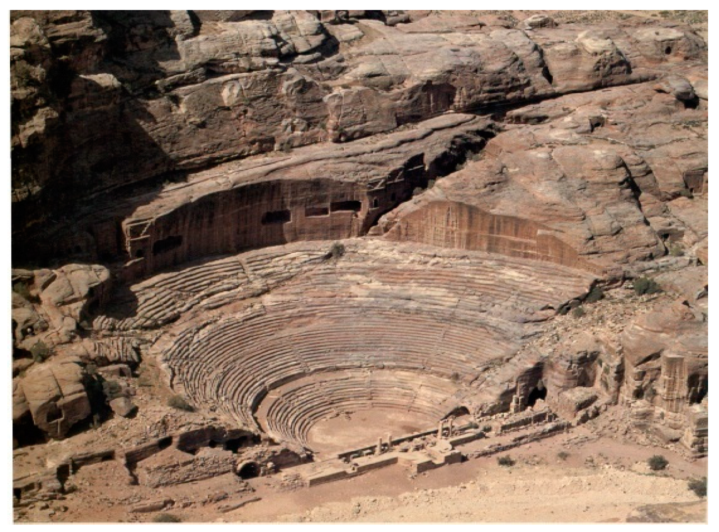
Figure 1 and supplied water to sites 12 to 18 (Appendix). A branch of this system may have extended to the eastern reaches of the housing district south of the Great Temple, as further excavations may indicate. A pipeline originating from the theater frontage area (
Figure 17), given the land contours shown in ([
37], p.136), would support a canal path to this area and sites along its path. The plateau shown in the Weis reference (Abb.5, p.136) [
37] indicates many water structures consistent with this water supply system.
A survey of the area from the Ain Braq, Ain Ammon springs (
Figure 1) revealed channels cut into mountain sides that supported a pipeline water supply from the two main springs to sites shown in
Figure 1. Some traces of an attempt to bridge a large valley by a siphon are indicated in
Figure 18. This design choice originated from a spring originating above the Wadi Mousa town that was likely abandoned early due to the necessity of constructing a large siphon across a deep valley to reach city precincts. The main Ain Braq and Ain Ammon springs supported a pipeline that sent water to the Lion Fountain (
Figure 19,
Appendix A Feature 14) and sites 12 to 18.
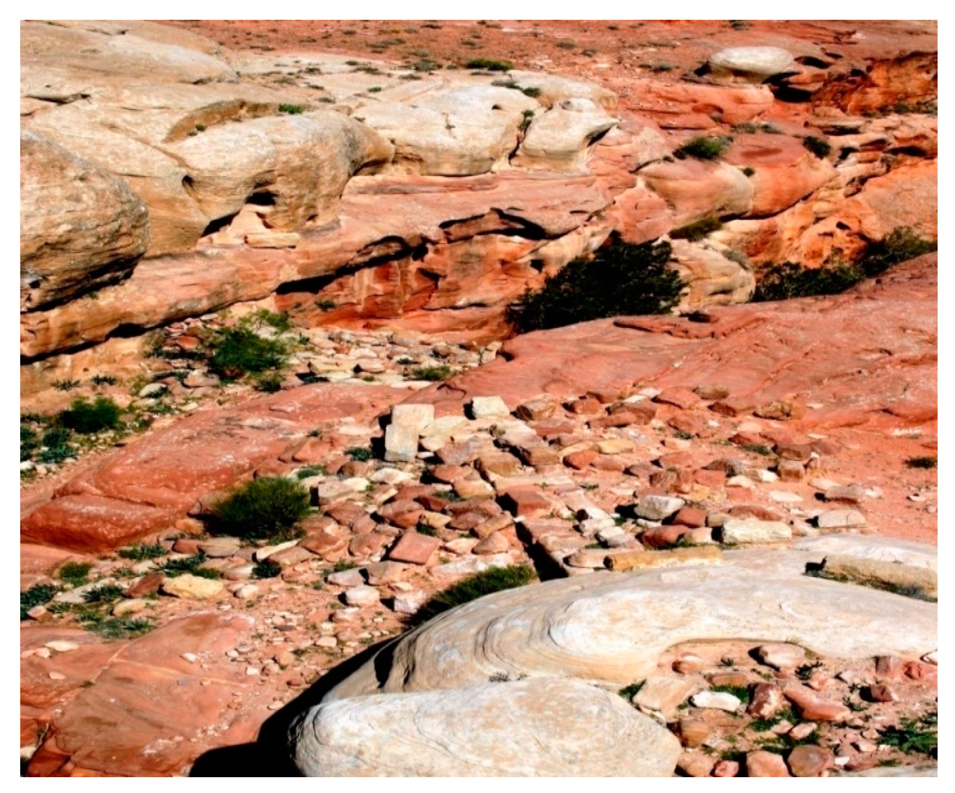
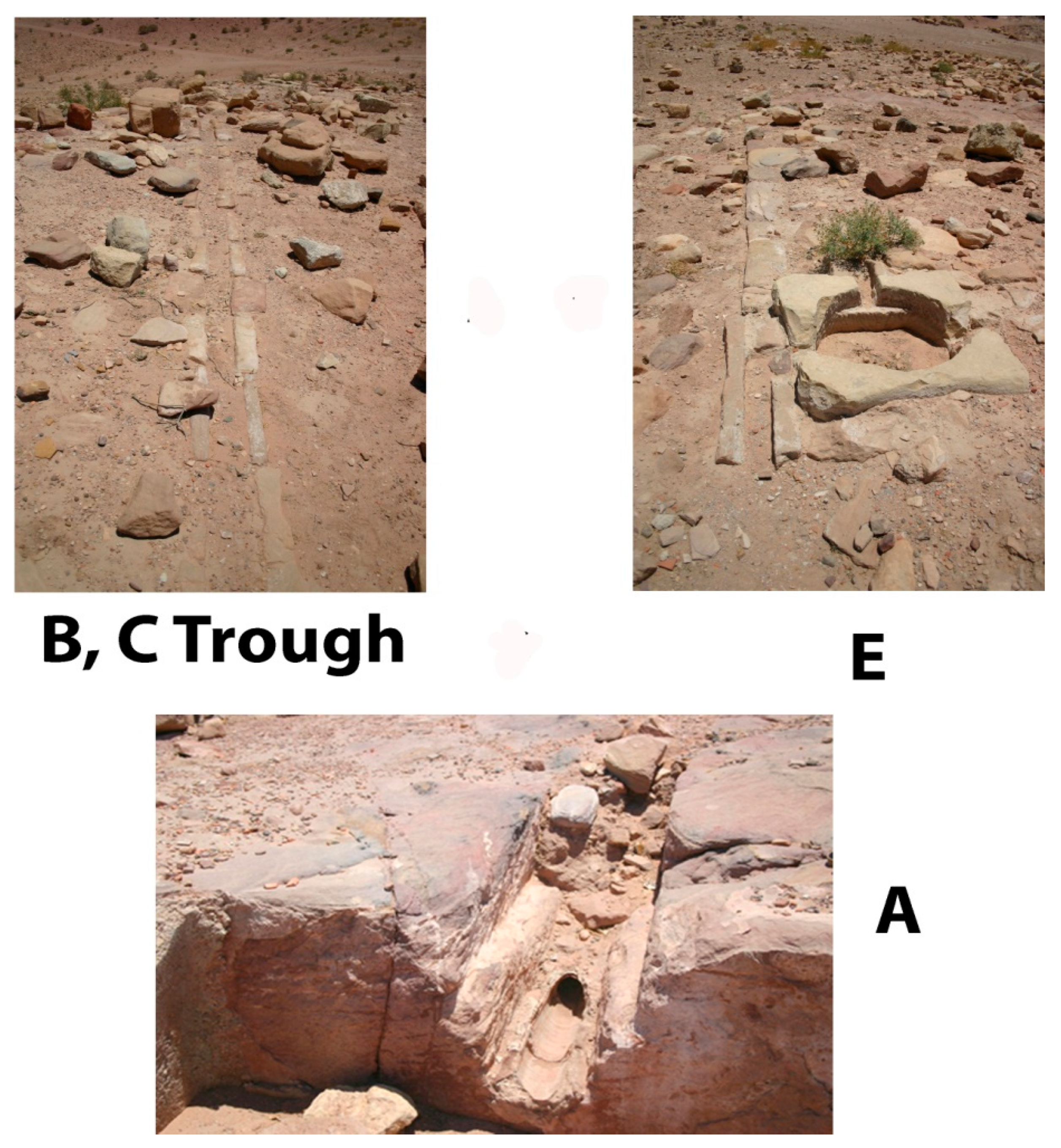
Figure 1 and
Figure 20 show surface water distribution features in the Wadi Farasa area (B-1,
Figure 1), together with the subterranean pipeline basin pit
A connecting to the distribution junction
E. Further exploration of possible contour pipeline paths threaded through mountainous areas to lower sites is necessary to establish the water supply source to
D, the Lion Fountain (
Figure 19), the Soldier’s Tomb area, and associated water basin structures sources by a branch of the Ain Braq pipeline. The contour map of the hill area south of the Great Temple (
Figure 12) area indicated the possibility of a water supply from a Southern Siq channel passing by the theater frontage (
Figure 16), but erosion changes in the landscape over millennia and multiple earthquake landscape disturbances have made the water supply connection to
D difficult to establish.
Of interest is the water supply to the Great Temple area. Starting from the hilltop junction (
Figure 1) above the Great Temple, a pipeline component assemblage exists (
Figure 20). While likely sourced by a Siq extension pipeline from the theater frontage area, there may have been a branch pipeline originating from the main Ain Braq, Ain Ammon pipeline as indicated in the B-3 area of
Figure 1. Independent of confirmation of this water source to the hill area above the Great Temple, the assemblage of water transfer components (
Figure 20) indicated water transfer to downhill housing areas with a probable pipeline water transfer to the Great Temple area. Combining excavated details of the
Figure 20 components, a FLOW-3D computer model is surmised in
Figure 21. One of the pipelines
B from
E led water to the lower Zhanthur housing district ([
37], p. 136), while another pipeline branch
C also served the same purpose; a possible branch of the
C pipeline may have led to the upper reaches of the Great Temple and lower Paradeisos area [
8,
20,
21] as further excavations may verify. On site conversations with Brown University personnel during excavation of the Great Temple area indicated that a pipeline element was found heading downhill to the Great Temple, but was now covered over from excavation soil from the Great Temple renovation activity. Independent of verification of this pipeline water supply to the Great Temple’s upper levels, much can be learned from existing
Figure 20 and
Figure 21 components that give insight into the hydraulic engineering knowledge base of Nabataean water engineers.
The FLOW-3D computer model (
Figure 21) composed of
Figure 20 components utilized an input water velocity consistent with
Figure 10 for full flow conditions into pressurized pipeline
D. The water supply input into
D was from the theater district (or from an Ain Braq branch pipeline) with a level portion of the pipeline existing before pipeline branches
E–
C and
E–
B continued water flow on to steeper terrain to supply downhill housing destinations and possibly the Great Temple upper level areas. A basin pit
A shows a connection pipeline adjacent to and connected into the
E pipeline.
For one hydraulic function, the basin pit pipeline
A (
Figure 21) served to divert flow away from the dual downhill pipeline
E–
B and
E–
C branches if these were blocked during repair or if the input flow at
D had flow surges past what the remaining downstream pipelines could accommodate. The blockage then diverted water to basin pit
A in
Figure 21. The flow into the basin pit continued until a pressure balance of water accumulated in basin pit
A balances with the pressure in water supply pipeline
D promoting an automatic system shut-off if the lower exit ports
B and
C (
Figure 21) were blocked. The more sophisticated hydraulic engineering use of the
Figure 21 configuration originated from the observation that subcritical full flow conditions existed in the lengthy, low slope supply pipeline
D. Due to the hydraulically steep declination angle in dual pipelines
E–
B and
E–C, input full flow past the junction area was converted to supercritical partial flow in both steep pipeline branches. This flow transition induced a local partial vacuum region above the partial flow water surface. As the branch pipeline exits were submerged into housing area reservoirs at their destination locations, then air was drawn into pipeline exit openings toward the upstream partial vacuum regions by flow patterns described in [
34]. The intermittent air bubble stream proceeded upstream into the dual steep declination pipelines’ branches to counter the partial vacuum region leading to flow intermittency and oscillatory hydraulic jumps in both the dual pipeline branches. This hydraulic phenomenon affected the flow stability of the entire system, leading to pulsating discharges into the downstream reservoirs as well as affecting the stability of input flow into
D. The pulsating flows induced internal pressure changes that could affect pipeline joint connections causing leakage. If pipeline exit flow into housing area reservoirs was free-fall, then the flow instability condition was even more severe as there was easier access of air going upstream to partial vacuum regions. A further cause for pipeline flow instability was the creation of a hydraulic jump within the pipelines due to internal pipeline wall roughness when subject to upstream supercritical flow. Many situations arose then that caused flow instabilities, leading to pulsating flow delivery tohousing area reservoirs and pressure variations that induced pipeline joint leakage.
A cure to unstable flow conditions was anticipated by Nabataean water engineers when air was supplied through basin pit pipeline
A as shown in
Figure 21. Air led into the partial vacuum region where it occurred canceled the partial vacuum region and air bubble transfer from pipeline exits and subsequent flow instabilities in the dual subterranean pipeline branches. The hydraulic jumps still occurred in
E–
B and
E–
C pipeline branches, but with the partial vacuum regions eliminated, the hydraulic jumps and flow within pipelines remained stable. In
Figure 21 A–C, the fluid fraction ff = 1 denotes water, ff = 0 denotes air, and intermediate ff values denote evaporative moisture levels. These figures indicate the transfer of air into the upstream reaches of
E pipelines through the basin pit pipeline
A. In summary, the basin pit pipeline connection served to minimize transient water surges originating from air pulses entering partial vacuum regions by providing an air passageway to
E and elimination of transient water instabilities in the downstream high declination slope dual pipelines. This was done by transferring backup water caused by transient hydraulic jump motion into the pit basin, thus preventing its effect on flow input stability.
Figure 21A shows incipient water transfer into the pit basin
A due to pipeline blockage.
Figure 21C shows continued filling of the pit basin until a pressure balance was achieved, shutting down further input water flow from
D.
Figure 21B shows that with air input from the connecting pipeline in
A to the main
E–
B and
E–
C pipelines, the partial vacuum regions were eliminated, producing stable partial flow in these pipeline branches.
Excavation of the Great Temple area over many years by the Brown University team under the direction of Martha Joukowski [
20,
21] revealed that rainfall seepage from a hillside wall south of the temple was collected into a drainage channel [
25] that led water to an underground reservoir on the east part of the site. A further subterranean channel starting from the surface entrance to the reservoir led water to the front platform part of the Great Temple site and likely served as an overflow drain channel activated when the reservoir was full. These additional water transfer features indicate that water supply to the Great Temple (and Paradeisos area) may have had an additional pipeline source from another branch of the
Figure 21 assemblage, which is yet to be discovered. Given Great Temple water supplies from the extension of the theater district piping at lower levels, possible higher level water supplies originated from the collection trench above the Great Temple north wall ([
25], pp. 265–267), as well as a possible connection from the
Figure 21C channel as previously noted. Previously, this trench was assigned a drainage collection channel role from rainfall seepage to protect the foundation stability of the Great Temple, but other uses were possibilities. Given the elaborate upper level community assemblage structure that likely represented [
20,
21] a site leadership meeting place, access to water at higher Great Temple levels appeared a necessity. Given that discussions with Brown University personnel involved in the excavation indicated that a pipeline existed coming down from the hill above the temple, now covered with excavation soil, gives credence to the water supply from a branch canal from pipeline
C shown in
Figure 21 or an extension pipeline from the theater system (
Figure 1). Future excavations are necessary to establish these connections to show the source of enigmatic structures that may have association with water transfer at upper levels of the Great Temple.
The Monastery Temple (
Figure 22) at high elevation above the urban city center had no apparent pipeline water supply system due to the absence of high-level springs, but rather a series of nearby water collection basins that collected rainfall runoff.
