Article

Sediment-Containing Sewage Separation Using Intermittent-Discharge Columnar Hydrocyclones

College of Mechanical & Electronic Engineering, Shandong University of Science and Technology, Qingdao 266590, China
*
Author to whom correspondence should be addressed.
Water 2020, 12(10), 2883; https://doi.org/10.3390/w12102883
Submission received: 14 August 2020 / Revised: 30 September 2020 / Accepted: 14 October 2020 / Published: 16 October 2020
(This article belongs to the Section Wastewater Treatment and Reuse)

Abstract

:
Traditional hydrocyclones can be used for the concentration of sewage-containing sediments, but the low underflow concentration and the high content of fine particles result in a large subsequent dehydration workload. This study aimed to investigate the effect of columnar hydrocyclone column height on separation performance and the change in the internal flow field after the underflow orifice of the hydrocyclone was closed, so as to provide a theoretical basis for improving the ability to treat the sewage of the hydrocyclone. Numerical simulation was used to examine the change in the separation performance of the hydrocyclone and the effect of column height on the separation performance of the hydrocyclone in the case of the closed underflow orifice during intermittent discharging. The results indicate that a proper increase in column height was beneficial to improve the separation performance of the hydrocyclone. With the increase in the closing time of the underflow orifice, the particle content at the bottom of the hydrocyclone increased significantly. The experiment proves the feasibility of the intermittent discharge method in practice, and this working method can effectively increase the underflow concentration.

1. Introduction

Sewage contains a large number of fine particles. If the sewage goes directly to the urban sewer without treatment, it easily causes problems, such as pipe blockage and serious pipe wear. Currently, the gravity sedimentation method is often used to treat sediment-containing sewage; however, it has the shortcomings of large site area, low sedimentation efficiency, high investment cost, and so forth. Hydrocyclones are often used for mineral separation and slurry concentration, and they can also be used in the treatment of sewage containing sediments. A hydrocyclone is a device [1,2,3,4] for the efficient separation of two-phase mixtures, using the principle of centrifugal sedimentation. It has the advantages of a simple structure, convenient operation, strong separation ability, and a small site area. Hydrocyclones play an increasingly important role in the pretreatment of sewage wastewater and surface sewage [5,6,7,8,9].
The separation of particles in a hydrocyclone is completed under the action of the flow field. The structural parameters and structural forms of the hydrocyclone directly affect the characteristics of the flow field, thereby affecting the separation and the separation performance of particles. Therefore, the research status at home and abroad is analyzed from the aspects of the effect of structural parameters and structural forms of the hydrocyclone on the separation performance.
The influence of structural parameters of a hydrocyclone on separation performance has been widely reported. Representative studies focus mainly on the cylindrical section of the hydrocyclone [10,11], the overflow pipe [12,13,14], the feed inlet [15,16,17], the underflow orifice [18,19,20,21], and the cone angle [20,22,23]. Numerical simulation and experimental methods obtain the effect of structural parameters on separation performance, providing an important theoretical reference for the structural optimization of the hydrocyclone.
In terms of the structural forms of the hydrocyclone, Jank et al. [24] proposed a large-diameter hydrocyclone for the pretreatment of sewage waste, separating impurities like sand and glass. Kyriakidis et al. [25] studied the micro-hydrocyclone group for separating fine particles in the wastewater, which significantly reduced the content of fine particles. However, when the hydrocyclone was used to treat low-concentration, sediment-containing wastewater, it caused a high moisture content of the underflow and high content of fine particles, thereby resulting in a large subsequent dehydration workload. Hence, the large-scale application of the hydrocyclone is limited in water treatment. To increase the underflow concentration of the hydrocyclone, Lin [26] proposed a hydraulic hydrocyclone with a thickening device outside the underflow tube. The solid particles at the bottom of the thickening device were taken away via the spiral discharging mechanism, and the concentration effect was significantly improved. Puprasert et al. [27] studied a large-diameter hydrocyclone equipped with a “Grit pot” for the pretreatment of sewage. Compared with the traditional hydrocyclone and sedimentation tank, the underflow concentration significantly increased. Although the storage device outside the underflow tube is an effective underflow thickening method [28,29], the underflow orifice and discharge opening can be easily blocked due to the longer accumulation time of materials in the external storage device.
This study proposed an intermittent-discharge columnar hydrocyclone. By closing the valve of the underflow orifice, the particles underwent centrifugal sedimentation inside the hydrocyclone. After a certain period of time, the valve of the underflow orifice was opened to discharge the material. After the hydrocyclone recovered normal operation, the valve of the underflow orifice was closed again. The cycle could achieve the purpose of increasing the underflow concentration. The effect of column height of the columnar hydrocyclone on the separation performance and the change of the internal flow field after the underflow of the hydrocyclone is closed are studied by numerical simulation methods, which provides a theoretical basis for improving the hydrocyclone. The experiment proves the feasibility of the intermittent discharge method in practical applications.

2. Materials and Methods

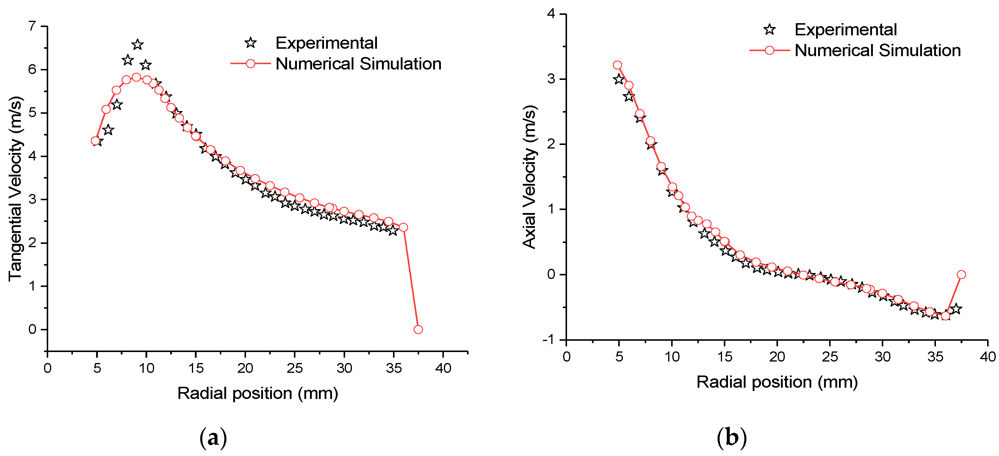
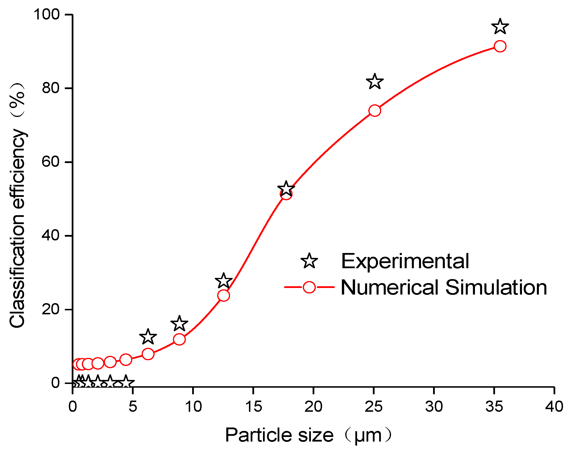
2.1. Model Description and Validation

With the development of computational fluid dynamics, numerical simulation has been widely used in the analysis and prediction of flow fields in a hydrocyclone. The Reynolds stress equation model (RSM) and the mixture model in the numerical simulations of hydrocyclones have been unanimously approved by researchers [16,30]. Nevertheless, it is still very important to determine the accuracy and reliability of the model before conducting numerical simulation research. In this paper, a 75 mm hydrocyclone is modeled, and the simulation results are compared with the experimental results of Hsieh [31]. The model verification is divided into two parts: the first part uses the mixture model to simulate the water–air flow, in order to verify the accuracy of the predicted velocity distribution, and the inlet velocity is 2.28 m/s; in the second part, the particle phase is set in the mixture model to verify the accuracy of predicting particle classification efficiency, and the inlet velocity is 2.5 m/s. The particle size and volume fraction settings are shown in Table 1. The data comparison cross-section is 60 mm downwards from the top cover of the hydrocyclone.
Figure 1a,b show the tangential velocity and axial velocity distribution curves. respectively. It can be seen from the Figure 1 that the mixture model can accurately predict the velocity distribution of the flow field inside the hydrocyclone, which is consistent with the research report by Kuang [32].
Figure 2 shows the classification efficiency curve. It can be seen from the Figure 2 that the classification efficiency obtained by the mixture model is consistent with the experimental results. The fine particles in the hydrocyclone are difficult to separate from the water, and its classification efficiency is closely related to the water split ratio. Figure 2 shows that the content of particles below 4.43 μm in the experimental results is 0, and the simulation results show that the classification efficiency of this part of the fine particles is about 5%, which is similar to the split ratio of water in the underflow of the hydrocyclone. Therefore, the difference in the classification efficiency of fine particles may be caused by experimental measurement errors [16]. It can be seen from the Figure 1 and Figure 2 that the mixture model and RSM model can accurately predict the flow field velocity and classification efficiency of the hydrocyclone.

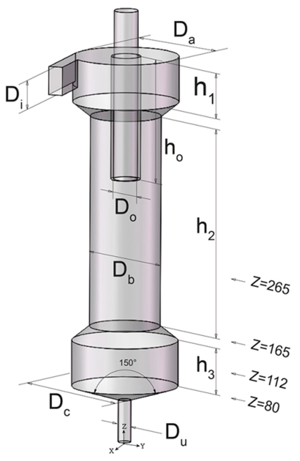
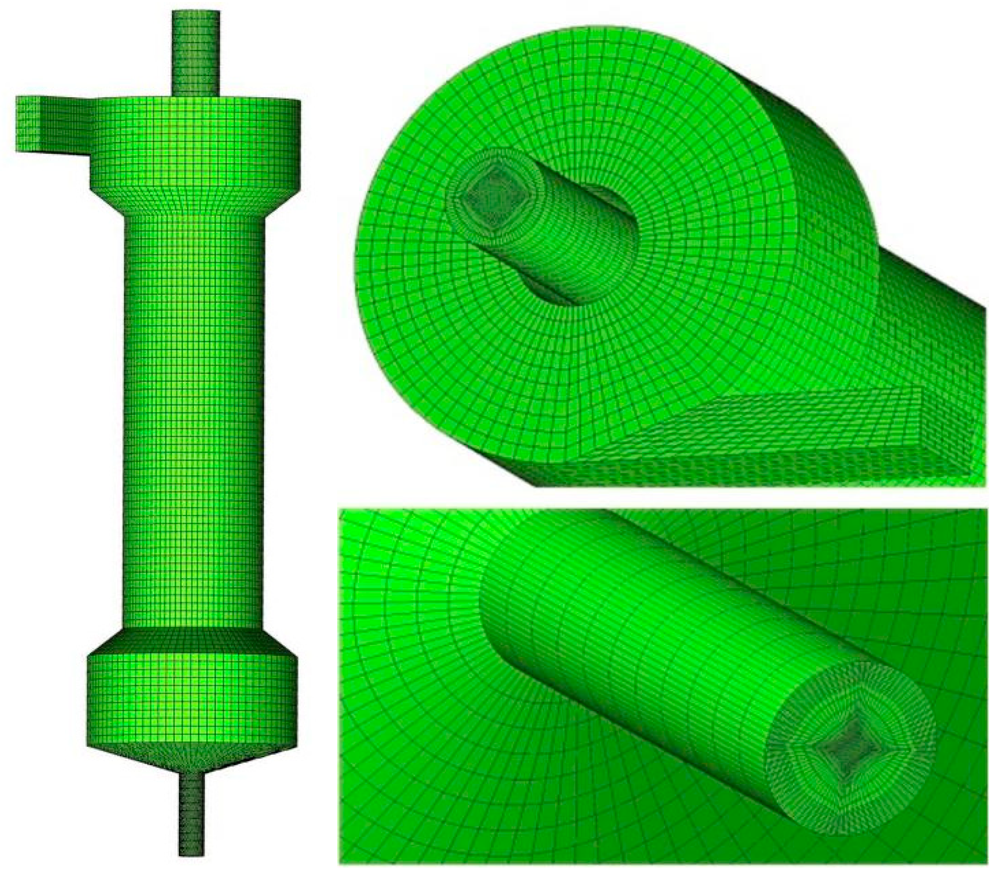
2.2. Hydrocyclone Geometry and Mesh Generation

Figure 3 is a structural diagram of the hydrocyclone. In the figure, the reference cross-section positions of the simulation data analysis are located at Z = 80 mm, Z = 112 mm, Z = 165 mm, and Z = 265 mm. To study the characteristics of the internal flow field of the hydrocyclone, the software SolidWorks2014 was used to establish the three-dimensional (3D) model of the fluid domain of the hydrocyclone. To study the effect of the column height on the separation performance of the hydrocyclone, the column height (h2) was selected as 220 mm, 260 mm, 300 mm, and 340 mm. The specific structural parameters are shown in Table 2. Among them, Di is the equivalent diameter of the feed port, Do is the diameter of the overflow port, Du is the diameter of the underflow port, and ho is the insertion depth of the overflow pipe. ICEM CFD 14.5 was used for mesh generation. The hexahedral structured grid generation method is used to divide the computational domain into 207,116 mesh units. The mesh generation is shown in Figure 4.

2.3. Boundary Conditions

The simulated material was a mixture of water and quartz sand, and the feed mass concentration was 4%. The set particle size composition is shown in Table 3.
The mixture model [33,34] and RSM [35,36] were adopted, the inlet of the hydrocyclone was set as the “velocity-inlet”, and the feeding rate was 6.3 m/s. Overflow and underflow were set as “pressure-outlet”. The boundary condition was set to “no-slip wall”. The pressure–velocity coupling SIMPLE numerical method was used for solving the control parameters. The discrete pressure and momentum formats of the control equations were the PRESTO! and QUICK formats, respectively.
A transient solution method was adopted to compare and study the changing trend of the flow field inside the hydrocyclone over time after the underflow orifice was closed. The residual error was set to 10−4, the time step was 1 × 10⁻⁵ s, and the boundary conditions of the underflow orifice were set to the wall at 4 s.

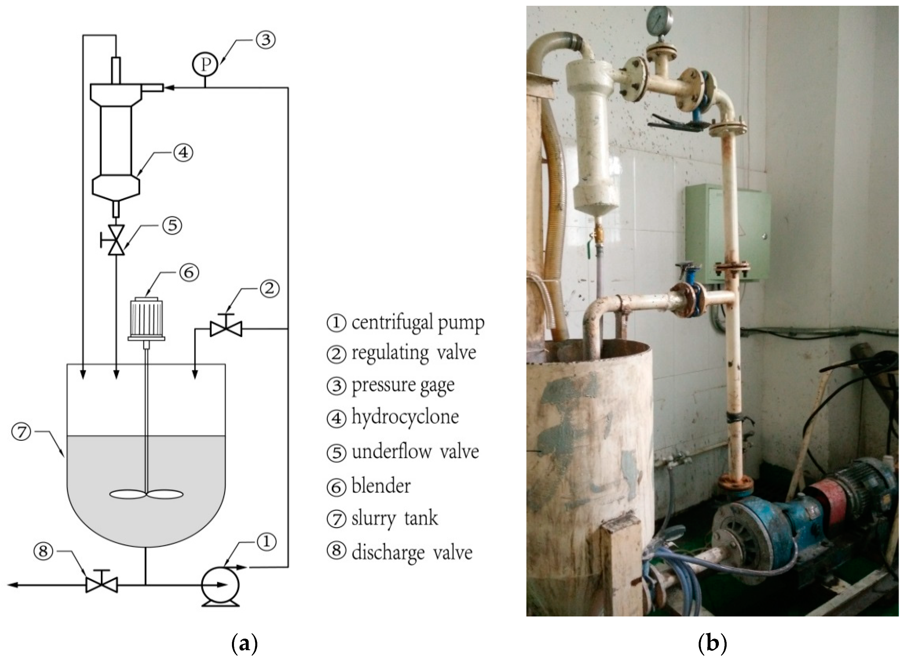
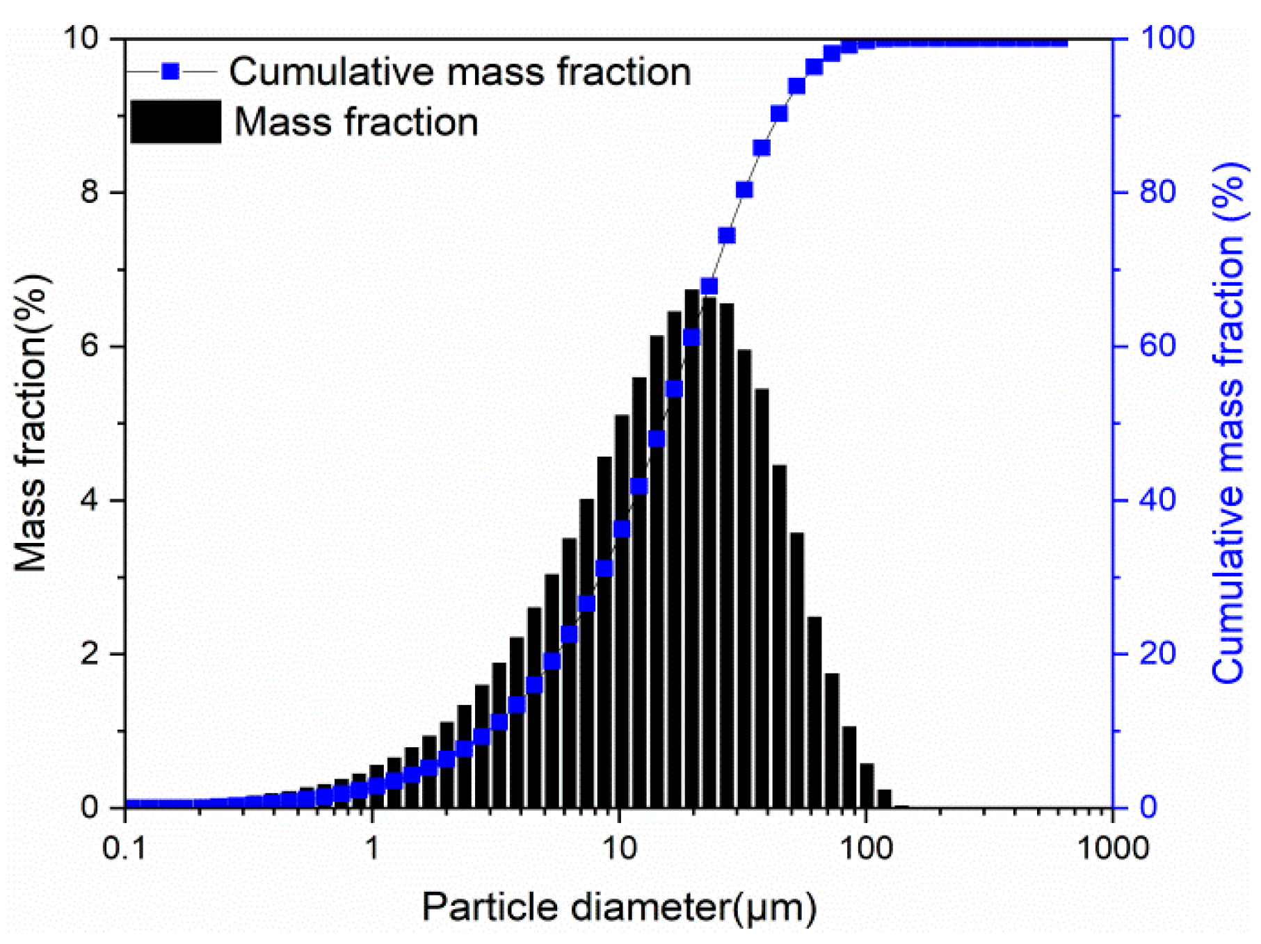
2.4. Experiment Test Method

In order to verify whether the intermittent discharge method can effectively increase the underflow concentration, we conducted corresponding experiments, which are of great significance for guiding practical applications. The experimental device for testing the separation performance of columnar hydrocyclone is shown in Figure 5. It is mainly composed of a slurry tank, blender, centrifugal pump, pressure gage, and valves. As shown in Figure 5, the underflow valve in the experimental device is a ball valve, the regulating valve and the discharge valve are butterfly valves, and the pressure gauge is a diaphragm pressure gauge. The regulating valve is installed between the centrifugal pump and the inlet of the columnar hydrocyclone to regulate the pressure or flow of the inlet. The underflow valve is used to control the opening and closing of the underflow port of the columnar hydrocyclone. The material used in the experiment is quartz sand with a density of 2700 kg/m3, and its particle size distribution is shown in Figure 6. In this experiment, the laser particle size analyzer (Mastersizer 2000, Malvern, England) was used to measure the particle size in the experimental sample.
The mass concentration of the quartz sand slurry was 4%. During the experiment, the pressure of the pressure gauge was adjusted to 0.1 MPa through the regulating valve. After the experiment ran smoothly, samples were taken from the hydrocyclone’s overflow, bottom flow, and feed. After that, the underflow valve was closed and a sample was taken from the overflow every 4 s. After a certain period of time, the underflow valve was opened and the underflow sample was taken.

3. Results and Discussion

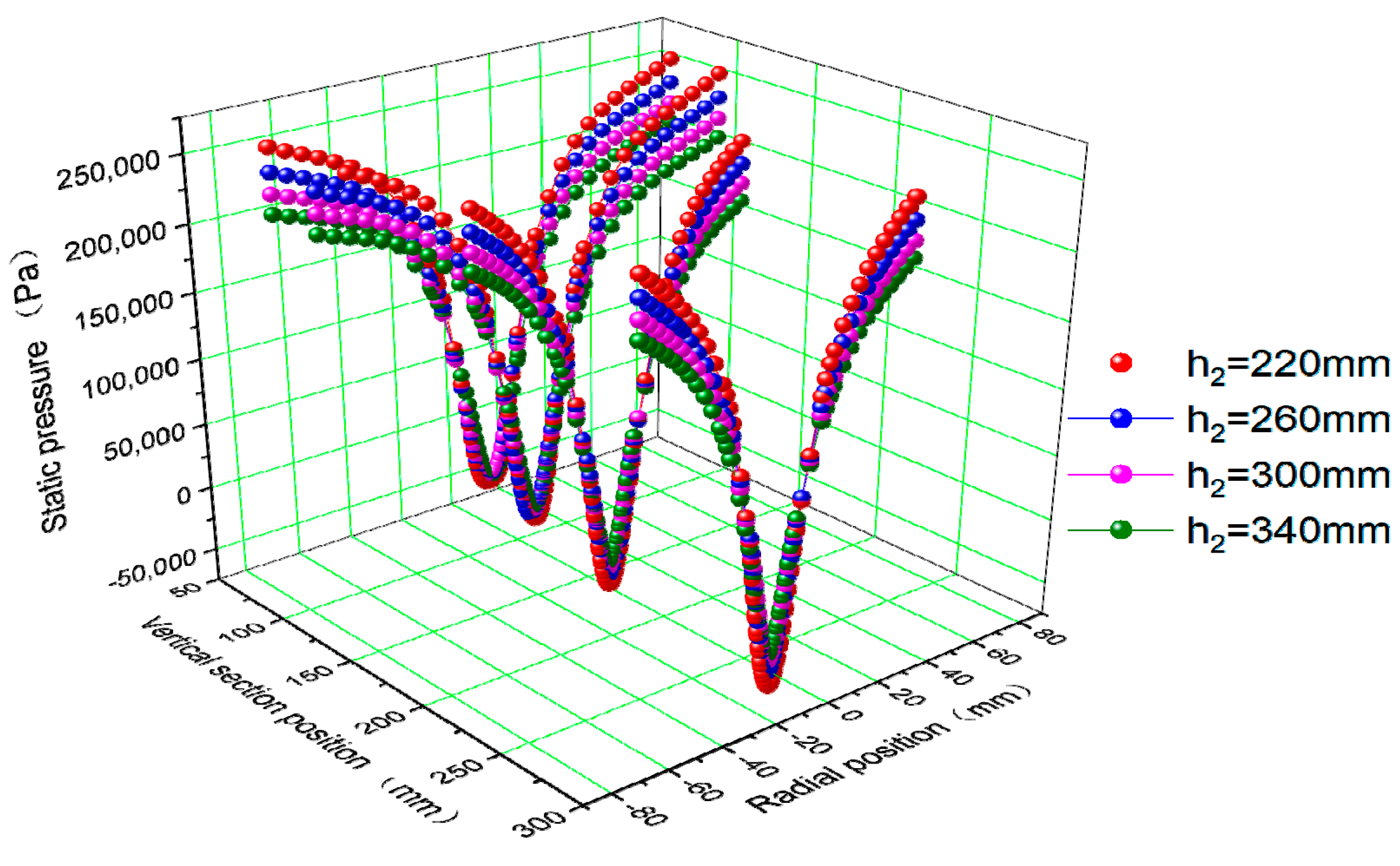
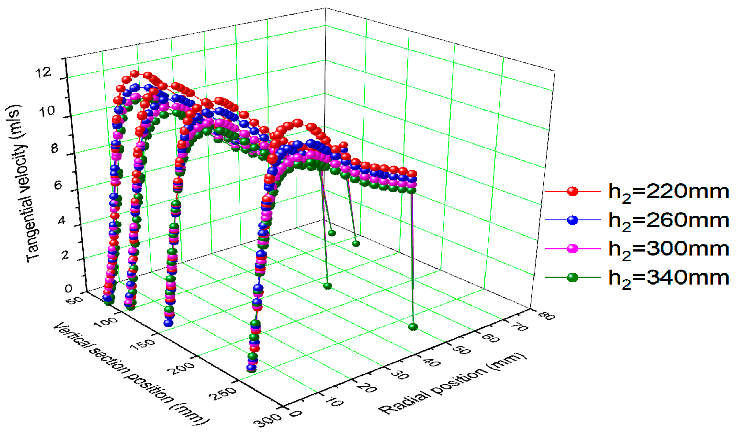
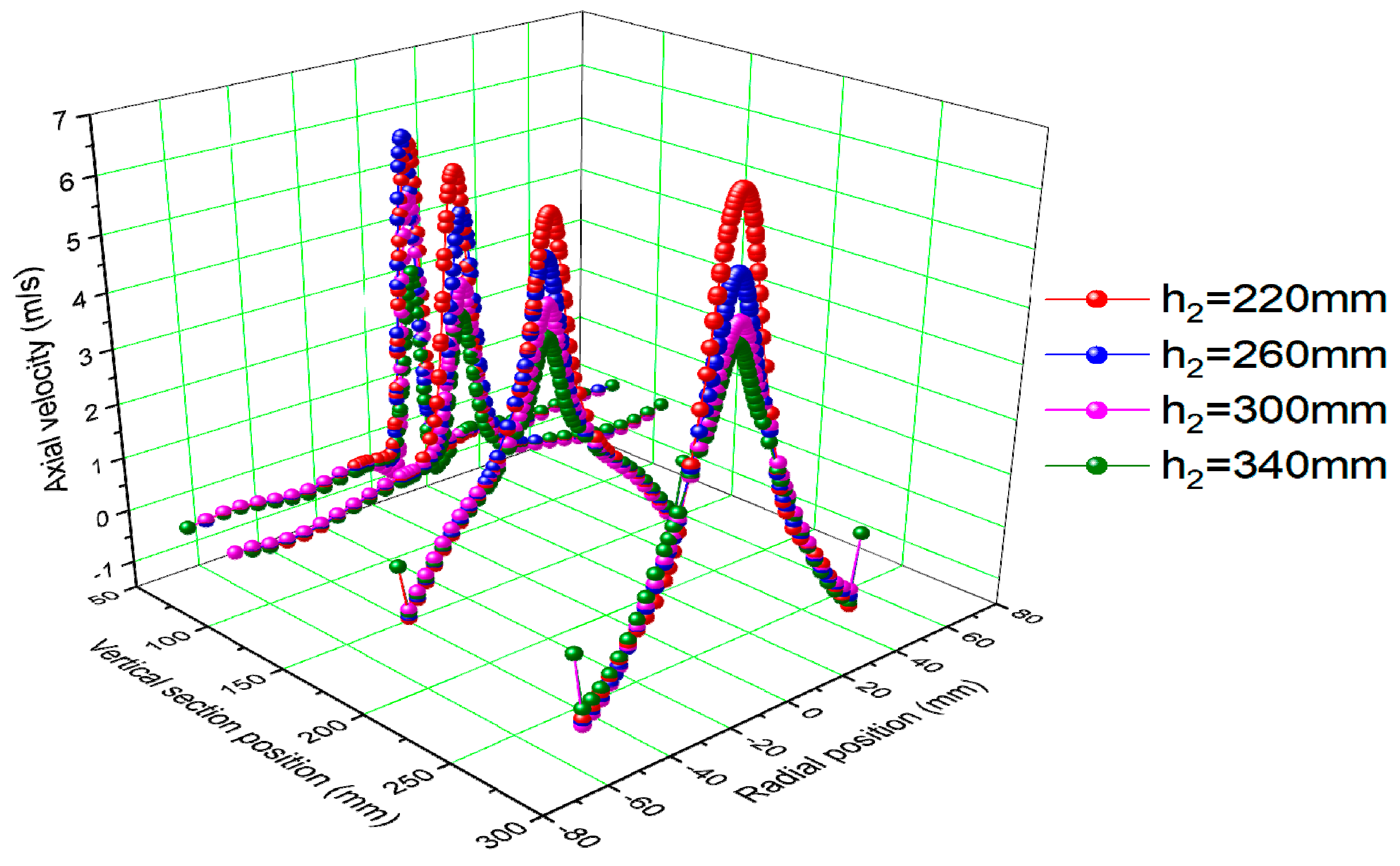
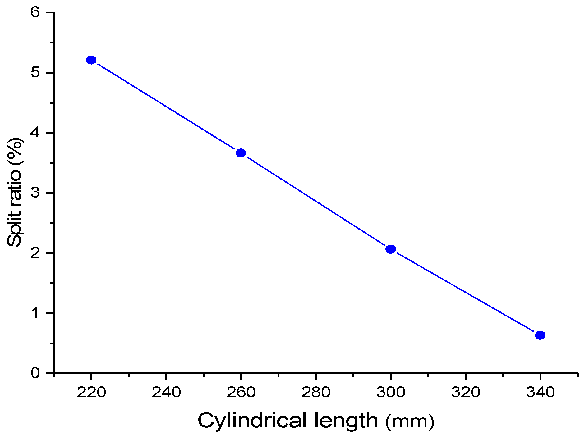
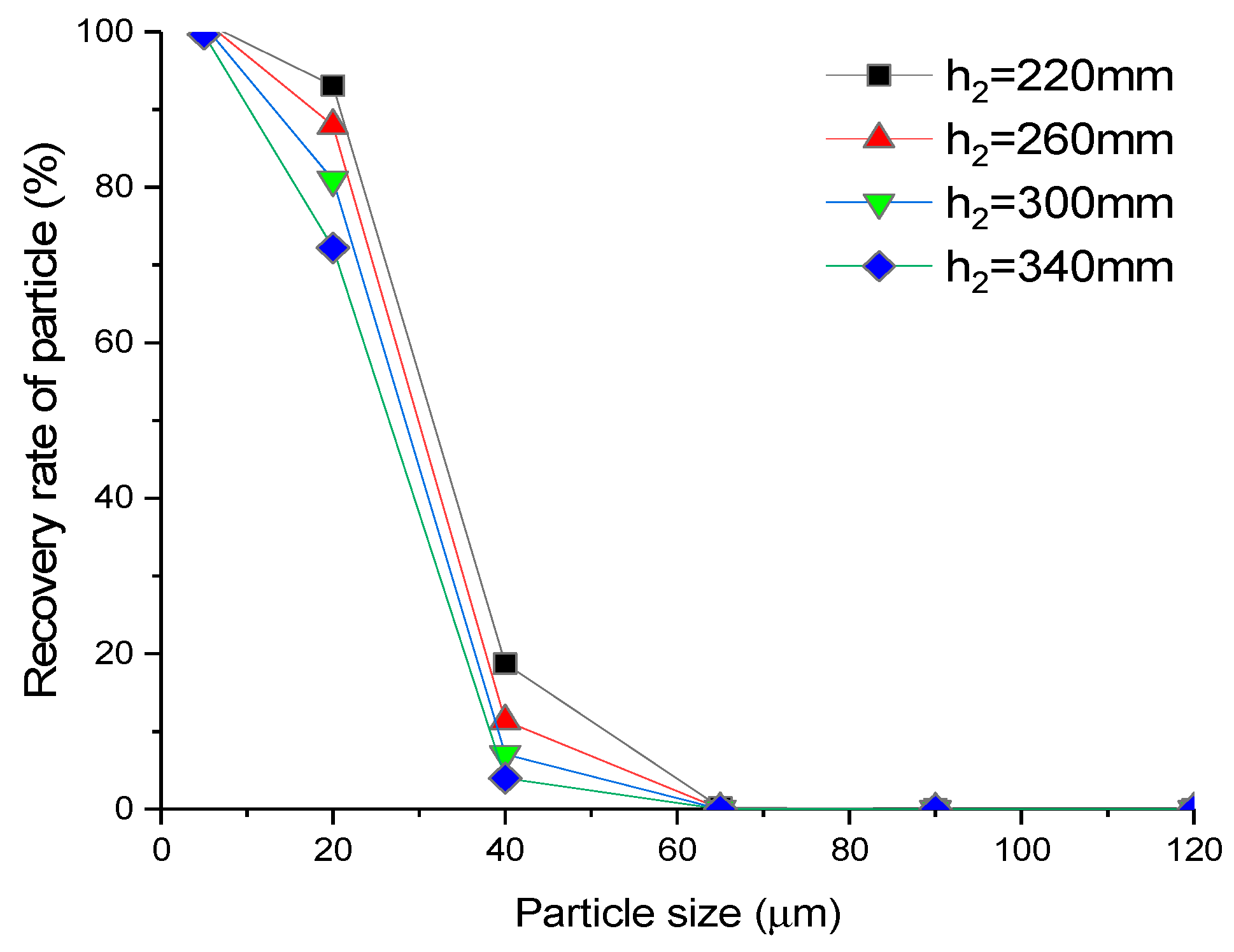
3.1. Effects of H2 on the Separation Performance of the Hydrocyclone

Figure 7 shows the distribution curve of static pressure inside the hydrocyclone. The figure reveals that the pressure distribution in different sections inside the hydrocyclone was basically the same, the pressure at the axial position exhibited a negative value, and the pressure value increased and reached the maximum value near the wall of the hydrocyclone with the increase in radius [16]. As the column height increased, the space that actually participated in the separation and the residence time of particles in the hydrocyclone increased, which was beneficial for improving the separation effect. However, it can be seen that the pressure values at different cross-section positions decreased with the increase in the column height, which increased the pressure loss of the hydrocyclone.
Figure 8 is the distribution curve of tangential velocity. It shows that the tangential velocity was zero near the wall, gradually increased with the decrease in radius, reached a maximum value at about 20 mm from the axis, and then decreased rapidly. This change trend is consistent with literature [16], which proves the accuracy of the simulation. As the column height increased, the maximum tangential velocity at various cross-section positions inside the hydrocyclone decreased. The decrease in tangential velocity reduced the centrifugal force, increased the separation size, and increased the coarse particles in the underflow. At the same time, as the column height increased, the separation space of the hydrocyclone and the residence time of particles in the hydrocyclone increased, which made the particle separation more thorough.
Figure 9 shows the distribution curve of axial velocity. The distribution of axial velocity affected the separation and residence time of particles in the hydrocyclone, determined the flow distribution of underflow and overflow, and was one of the important factors affecting the separation effect of the hydrocyclone. As the cross-sectional height decreases, the axial velocity becomes smaller, especially in the area near the underflow where the axial velocity is close to 0, and tends to stabilize in the radial position. This change may be caused by the increase in diameter near the underflow, which is beneficial to the stability of the flow field to a certain extent. As the column height increased, the maximum value of the axial velocity decreased significantly, effectively increasing the residence time of particles in the hydrocyclone and making the separation more thorough.
Figure 10 demonstrates the effect of column height on the split ratio. The high content of fine particles, large flow, and a low concentration resulted in a large pressure on subsequent dehydration. Therefore, the flow and the concentration of the underflow were expected to be lower and higher, respectively. The smaller split ratio was more beneficial to actual production. The figure shows that the split ratio decreased significantly with the increase in column height, indicating that the longer the column segment, the larger the underflow concentration.
Figure 11 shows the effect of column height on the recovery rate of overflow particles. Figure 11 shows that the particle content in the overflow decreases with the increase of the tower height, and this trend is particularly obvious for particles between 20 μm and 40 μm. Most particles in the overflow had particle sizes less than 65 μm, indicating that particles with sizes of 65 μm and above had good separation effects.
Figure 12 demonstrates the effect of column height on the pressure drop ratio. Hydrocyclones have pressure loss during the separation process, and the increase in pressure drop causes an increase in energy loss. As the overflow pressure drop (difference between overflow pressure and feed pressure) and underflow pressure drop (difference between underflow pressure and feed pressure) cannot be used to evaluate the overall pressure drop of the hydrocyclone, the pressure drop ratio (ratio of overflow pressure drop to underflow pressure drop) was adopted to evaluate the pressure loss. The figure shows that the pressure drop ratio of the hydrocyclone increased with the increase in column height. Although the increase in column height was beneficial to improve the separation effect to a certain extent, too large of a column height made the pressure loss of the hydrocyclone larger.

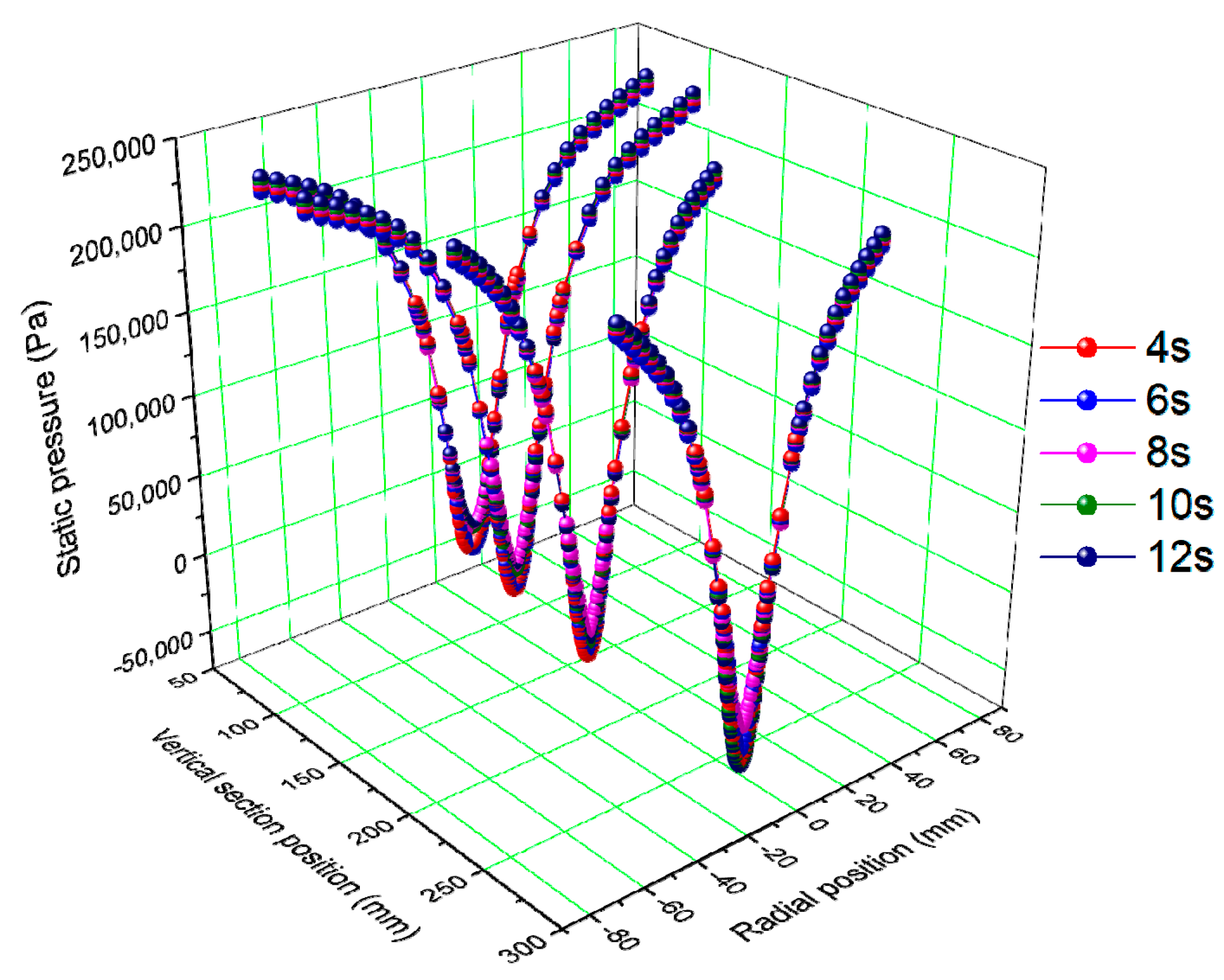
3.2. Effects of Intermittent Discharge on the Separation Performance of the Hydrocyclone (h2 = 300 mm)

The pressure loss along the radial direction during the separation process of the hydrocyclone is the main basis for calculating the production capacity and studying the energy loss, and it also has an important influence on the separation particle size and separation efficiency [16]. Figure 13 shows that the closure of the underflow orifice had little effect on the internal pressure distribution of the hydrocyclone, indicating that closing the underflow orifice did not affect the internal separation strength of the hydrocyclone.
Figure 14 shows that the tangential velocity at each cross-section position of the hydrocyclone decreased slightly with time after the underflow orifice was closed. Additionally, the lower the cross-section position, the more obvious the phenomenon. This was because the particles settled and accumulated inside the hydrocyclone, the concentration of the material at the bottom of the hydrocyclone increased, and the resistance within the fluid increased after the underflow orifice was closed, causing a gradual decrease in the tangential velocity. Meanwhile, the tangential velocity at the cross-section position Z = 80 mm remained at a high level, indicating that the bottom material of the hydrocyclone was still in a strong motion state, which was clearly different from other hydrocyclones with external storage devices, and was beneficial to avoid the blocking problem caused by the static accumulation of the bottom material.
Figure 15 shows that the axial velocity at the axial center increased with the increase in the closing time of the underflow orifice. The higher the cross-section position, the more obvious the changing trend. As the axial velocity increased, the residence time of the particles in the hydrocyclone became shorter, and some materials were discharged from the overflow before the effective separation was completed, which made the separation performance of the hydrocyclone worse.
Figure 16 shows that the volume fraction of coarse particles above 40 μm at the bottom of the hydrocyclone increased significantly with time after the underflow orifice was closed. The longer the closing time, the more obvious the particle accumulation at the underflow orifice. This phenomenon indicated that the longer the closing time of the underflow orifice, the more beneficial it was to increase the underflow concentration. However, the closing time of the underflow orifice was too long, which was likely to cause the blockage of the underflow orifice. Therefore, the reasonable selection of the closing time of the underflow orifice required continuous experiments.
Figure 17 demonstrates the distribution of the velocity vector. A circulating flow was observed at the bottom of the hydrocyclone, and the circulating flow always existed within 4–12 s after the underflow orifice was closed. Some particles were not completely separated and deposited at the bottom to re-enter the separation area, due to the presence of underflow circulation in the hydrocyclone, which was beneficial to improve separation accuracy.

3.3. Experiment Results Analysis

Figure 18 shows the effect of underflow valve closing time on overflow concentration. Figure 19 shows the effect of the closing time of the underflow valve on the median diameter of overflow particles. It can be seen from Figure 18 and Figure 19 that when the underflow valve is closed, the overflow concentration and the median diameter of the overflow particles increase with time. It is worth noting that the overflow product changes at 32 s. At this moment, the underflow valve opens, and with the high concentration of material gradually discharged from the bottom flow, the overflow concentration and median particle size of the overflow particles decrease obviously. This shows that the intermittent discharge hydrocyclone does not affect the overflow separation accuracy.
Table 4 is a comparison of underflow products under conventional discharge and intermittent discharge conditions. As shown in Table 4, the concentration of the intermittent discharge underflow product is 44.37%, and the median diameter of the particles has been significantly improved. The particle distribution cloud in Figure 16 shows the reason for the increase in underflow concentration. When the underflow valve is closed, the residence time of coarse particles in the hydrocyclone increases, and these coarse particles enter the outer vortex and accumulate at the bottom of the hydrocyclone. At the same time, as shown in Figure 17, the bottom space of the columnar hydrocyclone is larger than that of the conventional hydrocyclone, so the internal elutriation effect is enhanced; this means that more fine particles enter the inner swirling, which causes the proportion of coarse particles in the underflow product to increase and the median diameter of the particles to increase. The experimental results show that the intermittent discharge can significantly increase the concentration of underflow and reduce the content of fine particles in the underflow.

4. Conclusions

This study proposed an intermittent-discharge columnar hydrocyclone. The material settled and accumulated inside the hydrocyclone by closing the underflow valve. After a certain time, the underflow valve was opened to discharge the material, so as to increase the underflow concentration and reduce the content of fine particles. Through numerical simulation, the following conclusions were obtained:
(1)
The column height has a greater effect on the separation performance of the hydrocyclone. The tangential and axial speeds of the hydrocyclone decrease with the increase in the column height, which is beneficial for the stability of flow fields in the hydrocyclone. However, increasing column height enhances the pressure loss of the hydrocyclone. Therefore, a reasonable choice of column height is very important for the separation performance of the hydrocyclone.
(2)
After the underflow orifice is closed, the tangential speed of the hydrocyclone gradually decreases, and the axial speed gradually increases, which increases the content of fine particles in the overflow. A circulating flow occurs at the bottom of the hydrocyclone. The fine particles enter the overflow under the effect of the circulating flow, which is beneficial for reducing the content of fine particles in the underflow of the hydrocyclone and improving the separation accuracy and underflow concentration.
(3)
The intermittent-discharge columnar hydrocyclone still maintains high tangential speed and centrifugal separation strength, which improves the underflow blockage problem caused by material deposition to a certain extent.
The findings of this study might guide the practical application of the intermittent-discharge columnar hydrocyclone. However, many problems remain unresolved, such as the effect of feeding rate, column diameter, and so forth, with regard to the separation performance of the hydrocyclone and the optimized interval of determining the opening and closure of the underflow orifice.

Author Contributions

Conceptualization, Y.Z.; data curation, M.Y.; formal analysis, Y.Z. and M.Y.; investigation, Y.Z. and P.L.; methodology, Y.Z. and P.L.; software, M.Y.; writing—original draft, Y.Z.; writing—review and editing, P.L. All authors have read and agreed to the published version of the manuscript.

Funding

This research was funded by National Key R&D Program of China (no. 2018YFC0604702).

Conflicts of Interest

The authors declare no conflict of interest.

References

  1. Ji, L.; Kuang, S.B.; Qi, Z.; Wang, Y.; Chen, J.; Yu, A.B. Computational analysis and optimization of hydrocyclone size to mitigate adverse effect of particle density. Sep. Purif. Technol. 2017, 174, 251–263. [Google Scholar] [CrossRef]
  2. Razmi, H.; Goharrizi, A.S.; Mohebbi, A. CFD simulation of an industrial hydrocyclone based on multiphase particle in cell (MPPIC) method. Sep. Purif. Technol. 2019, 209, 851–862. [Google Scholar] [CrossRef]
  3. Vakamalla, T.R.; Mangadoddy, N. Numerical simulation of industrial hydrocyclones performance: Role of turbulence modelling. Sep. Purif. Technol. 2017, 176, 23–39. [Google Scholar] [CrossRef]
  4. Tian, J.Y.; Ni, L.; Song, T.; Shen, C.; Yao, Y.; Zhao, J.N. Numerical study of foulant-water separation using hydrocyclones enhanced by reflux device: Effect of underflow pipe diameter. Sep. Purif. Technol. 2019, 215, 10–24. [Google Scholar] [CrossRef]
  5. Sun, Y.; Liu, Y.; Zhang, Y.; Huang, Y.; Wang, L.; Dai, L.; Xu, J.; Wang, H. Hydrocyclone-induced pretreatment for sludge solubilization to enhance anaerobic digestion. Chem. Eng. J. 2019, 374, 1364–1372. [Google Scholar] [CrossRef]
  6. Xu, Y.X.; Wang, H.L.; Wang, Z.H.; Fang, Y.Y.; Liu, Y.; Zeng, T.; Liu, Z.B.; Liu, M. Hydrocyclone breakage of activated sludge to exploit internal carbon sources and simultaneously enhance microbial activity. Process. Saf. Environ. 2018, 117, 651–659. [Google Scholar] [CrossRef]
  7. Pećarević, M.; Mikuš, J.; Prusina, I.; Juretić, H.; Bratoš Cetinić, A.; Brailo, M. New role of hydrocyclone in ballast water treatment. J. Clean. Prod. 2018, 188, 339–346. [Google Scholar] [CrossRef] [Green Version]
  8. Lv, W.J.; Chen, J.Q.; Chang, Y.L.; Liu, H.L.; Wang, H.L. UU-type parallel mini-hydrocyclone group separation of fine particles from methanol-to-olefin industrial wastewater. Chem. Eng. Process. 2018, 131, 34–42. [Google Scholar] [CrossRef]
  9. Liu, Y.; Yang, Q.; Qian, P.; Wang, H.-l. Experimental study of circulation flow in a light dispersion hydrocyclone. Sep. Purif. Technol. 2014, 137, 66–73. [Google Scholar] [CrossRef]
  10. Patra, G.; Velpuri, B.; Chakraborty, S.; Meikap, B.C. Performance evaluation of a hydrocyclone with a spiral rib for separation of particles. Adv. Powder Technol. 2017, 28, 3222–3232. [Google Scholar] [CrossRef]
  11. Wang, C.Z.; Chen, J.Z.; Shen, L.J.; Ge, L.H. Study of flow behaviour in a three products hydrocyclone screen: Numerical simulation and experimental validation. Physicochem. Probl. Miner. Process 2019, 55, 879–895. [Google Scholar] [CrossRef]
  12. He, F.Q.; Zhang, Y.H.; Wang, J.G.; Yang, Q.; Wang, H.L.; Tan, Y.H. Flow Patterns in Mini-Hydrocyclones with Different Vortex Finder Depths. Chem. Eng. Technol. 2013, 36, 1935–1942. [Google Scholar] [CrossRef]
  13. Wang, B.; Yu, A.B. Numerical study of the gas-liquid-solid flow in hydrocyclones with different configuration of vortex finder. Chem. Eng. J. 2008, 135, 33–42. [Google Scholar] [CrossRef]
  14. Xu, Y.X.; Fang, Y.Y.; Wang, Z.H.; Guo, D.; Liu, Y.; Huang, Y.; Fu, P.B.; Jin, J.H.; Wei, C.W.; Wang, H.L.; et al. In-situ sludge reduction and carbon reuse in an anoxic/oxic process coupled with hydrocyclone breakage. Water Res. 2018, 141, 135–144. [Google Scholar] [CrossRef] [PubMed]
  15. Vieira, L.G.M.; Silva, D.O.; Barrozo, M.A.S. Effect of Inlet Diameter on the Performance of a Filtering Hydrocyclone Separator. Chem. Eng. Technol. 2016, 39, 1406–1412. [Google Scholar] [CrossRef]
  16. Zhang, C.; Wei, D.Z.; Cui, B.Y.; Li, T.S.; Luo, N. Effects of curvature radius on separation behaviors of the hydrocyclone with a tangent-circle inlet. Powder Technol. 2017, 305, 156–165. [Google Scholar] [CrossRef]
  17. Olson, T.J.; Van Ommen, R. Optimizing hydrocyclone design using advanced CFD model. Miner. Eng. 2004, 17, 713–720. [Google Scholar] [CrossRef]
  18. Hoffmann, A.C.; Skorpen, A.; Chang, Y.F. Positron emission particle tracking and CFD investigation of hydrocyclones acting on liquids of varying viscosity. Chem. Eng. Sci. 2019, 200, 310–319. [Google Scholar] [CrossRef]
  19. Schwarz, M.P.; Song, T.; Yang, T.H.; Zhou, J.W.; Wang, Q.K. Reconciliation of empirical correlations and CFD results for hydrocyclone performance for application in process modelling. Miner. Eng. 2019, 144. [Google Scholar] [CrossRef]
  20. Ye, J.X.; Xu, Y.X.; Song, X.F.; Yu, J.G. Numerical modelling and multi-objective optimization of the novel hydrocyclone for ultra-fine particles classification. Chem. Eng. Sci. 2019, 207, 1072–1084. [Google Scholar] [CrossRef]
  21. Zhao, L.; Jiang, M.; Wang, Y. Experimental study of a hydrocyclone under cyclic flow conditions for fine particle separation. Sep. Purif. Technol. 2008, 59, 183–189. [Google Scholar] [CrossRef]
  22. Cao, Y.Q.; Jin, Y.; Li, J.; Zou, D.; Chen, X. Demulsification of the phosphoric acid-tributyl phosphate (W/O) emulsion by hydrocyclone. Sep. Purif. Technol. 2016, 158, 387–395. [Google Scholar] [CrossRef]
  23. Vieira, L.G.M.; Silva, D.O.; Barrozo, M.A.S. Study of the Performance of a Novel Hydrocyclone Built in the Configurations of the Classical Families. Sep. Sci. Technol. 2013, 48, 2700–2706. [Google Scholar] [CrossRef]
  24. Jank, A.; Muller, W.; Waldhuber, S.; Gerke, F.; Ebner, C.; Bockreis, A. Hydrocyclones for the separation of impurities in pretreated biowaste. Waste Manag. 2017, 64, 12–19. [Google Scholar] [CrossRef]
  25. Kyriakidis, Y.N.; Silva, D.O.; Barrozo, M.A.S.; Vieira, L.G.M. Effect of variables related to the separation performance of a hydrocyclone with unprecedented geometric relationships. Powder Technol. 2018, 338, 645–653. [Google Scholar] [CrossRef]
  26. Lin, I.J. Hydrocycloning Thickening: Dewatering and Densification of Fine Particulates. Sep. Sci. Technol. 1987, 22, 1327–1347. [Google Scholar] [CrossRef]
  27. Puprasert, C.; Hebrard, G.; Lopez, L.; Aurelle, Y. Potential of using Hydrocyclone and Hydrocyclone equipped with Grit pot as a pre-treatment in run-off water treatment. Chem. Eng. Process. Process Intensif. 2004, 43, 67–83. [Google Scholar] [CrossRef]
  28. Endres, E.; Dueck, J.; Neesse, T. Hydrocyclone classification of particles in the micron range. Miner. Eng. 2012, 31, 42–45. [Google Scholar] [CrossRef]
  29. Neesse, T.; Dueck, J.; Schwemmer, H.; Farghaly, M. Using a high pressure hydrocyclone for solids classification in the submicron range. Miner. Eng. 2015, 71, 85–88. [Google Scholar] [CrossRef]
  30. Ji, L.; Kuang, S.B.; Yu, A.B. Numerical Investigation of Hydrocyclone Feed Inlet Configurations for Mitigating Particle Misplacement. Ind. Eng. Chem. Res. 2019, 58, 16823–16833. [Google Scholar] [CrossRef]
  31. Hsieh, K.T.; Rajamani, K. Phenomenological model of the hydrocyclone: Model development and verification for single-phase flow. Int. J. Miner. Process. 1988, 22, 223–237. [Google Scholar] [CrossRef]
  32. Kuang, S.B.; Chu, K.W.; Yu, A.B.; Vince, A. Numerical study of liquid-gas-solid flow in classifying hydrocyclones: Effect of feed solids concentration. Miner. Eng. 2012, 31, 17–31. [Google Scholar] [CrossRef]
  33. Jiang, J.; Ying, R.; Feng, J.A.; Wang, W.B. Computational and Experimental Study of the Effect of Operating Parameters on Classification Performance of Compound Hydrocyclone. Math. Probl. Eng. 2018. [Google Scholar] [CrossRef] [Green Version]
  34. Tian, J.Y.; Ni, L.; Song, T.; Shen, C.; Zhao, J.N. Numerical study of foulant-water separation using hydrocyclones enhanced by ejection device: Effect of ejection velocity. Energy 2018, 163, 641–659. [Google Scholar] [CrossRef]
  35. Chu, K.; Chen, J.; Yu, A. Applicability of a coarse-grained CFD–DEM model on dense medium cyclone. Miner. Eng. 2016, 90, 43–54. [Google Scholar] [CrossRef]
  36. Yang, Q.; Lv, W.J.; Ma, L.; Wang, H.L. CFD study on separation enhancement of mini-hydrocyclone by particulate arrangement. Sep. Purif. Technol. 2013, 102, 15–25. [Google Scholar] [CrossRef]
Figure 1. Comparison of distribution of tangential velocity (a) and axial velocity (b).
Water 12 02883 g001
Figure 2. Comparison of classification efficiency curves between numerical simulation and experiment.
Water 12 02883 g002
Figure 3. Structural diagram of the hydrocyclone.
Water 12 02883 g003
Figure 4. Mesh generation.
Water 12 02883 g004
Figure 5. Schematic diagram of the (a) experimental system and (b) experimental device.
Water 12 02883 g005
Figure 6. Particle size distribution in the experiment.
Water 12 02883 g006
Figure 7. Distribution curve of static pressure.
Water 12 02883 g007
Figure 8. Distribution curve of tangential velocity.
Water 12 02883 g008
Figure 9. Distribution curve of axial velocity.
Water 12 02883 g009
Figure 10. Effect of column height on the split ratio.
Water 12 02883 g010
Figure 11. Effect of column height on the recovery rate of overflow particles.
Water 12 02883 g011
Figure 12. Effect of column height on the pressure drop ratio.
Water 12 02883 g012
Figure 13. Distribution curve of static pressure.
Water 12 02883 g013
Figure 14. Distribution curve of tangential velocity.
Water 12 02883 g014
Figure 15. Distribution curve of axial velocity.
Water 12 02883 g015
Figure 16. Cloud diagram of the volume fraction change for particles.
Water 12 02883 g016aWater 12 02883 g016b
Figure 17. Velocity vector.
Water 12 02883 g017
Figure 18. Effect of closing time of the underflow valve on overflow concentration.
Water 12 02883 g018
Figure 19. Effect of closing time of the underflow valve on median diameter of overflow particles.
Water 12 02883 g019
Table 1. Size distribution and respective volume fraction of particles in the feed.
Size Interval (μm)Mean Size (μm)Volume Fraction (%)
−42.21 + 29.8535.500.622
−29.85 + 21.1025.100.734
−21.10 + 14.9217.740.722
−14.92 + 10.5512.550.508
−10.55 + 7.468.870.375
−7.46 + 5.276.270.365
−5.27 + 3.744.430.289
−3.73 + 2.633.130.185
−2.63 + 1.693.110.127
−1.69 + 1.011.310.116
−1.01 + 0.660.820.065
−0.66 + 0.430.530.032
Total 4.14
Table 2. Structural parameters of the hydrocyclone.
ParametersIntermittent-Discharge Column Segment (mm)
Do34
ho240
Di34
Du18
Da150
Db100
Dc150
h165
h2220/260/300/340
h365
Table 3. Particle size composition.
Particle Size of Quartz Sand5 μm20 μm40 μm65 μm90 μm120 μm
Volume fraction0.002740.004580.002700.002990.001810.00091
Table 4. Comparison of underflow products.
Underflow ProductConcentration (%)Median Diameter (μm)
Normal discharge15.8642.45
Intermittent discharge44.3755.83
Publisher’s Note: MDPI stays neutral with regard to jurisdictional claims in published maps and institutional affiliations.

