1. Introduction
As the main force-bearing component of a cable-stayed bridge, a durable stay cable is paramount to the serviceability, safety, and durability of the entire bridge. In the last ten or twenty years, there are two kinds of cable system used in cable stayed bridge mainly, one is parallel wire cable system, and another is steel stranded wire cable. The protection system of former consists with HDPE sheathing tube and filled materials, including cements and wax or grease, and galvanized layers adhere to each metal wires; and the protection system of latter consists with two layers HDPE sheathing tubes, the outer tube and the tube for individual strands, the filled materials between the tubes and steel wires, and galvanized layers adhere to each metal wires. In earlier years, the most adopted still material is cement mortar. Due to the poor ability in protecting the inner steel wires, cement mortar is not to be used in recent decades. Currently, the main anticorrosive material used for sheathing stay cables around the world is high-density polyethylene (HDPE), which is the key to ensuring the durability of this type of stay cable bridge [
1,
2]. Although this material has the advantages of anti-corrosiveness, toughness, hardness, resistance to scratching, and being economical, HDPE experiences fractures during use due to factors related to its production, construction technology, erosion, and the dynamic stress environment. There has been a recent surge in internationally reported cases of HDPE sheathing fractures in which approximately 60% of the fractures are due to factors related to force bearing during service [
3]. Regardless of the cause of these fractures, once a crack penetrates through to the inner metal wires, the cable is vulnerable to environmental corrosion [
4]. Therefore, cracking of HDPE sheathing is the first stage in the degradation of the entire cable system’s durability, and this degradation directly affects the cable’s safety. Despite there are three protection lines against the corrosion (
viz. galvanised layer, filled materials, and HDPE), generally the cracking of HDPE sheathing means the failure of first protection line. So in sense of engineering, to choose the cracking of HDPE sheathing as the durability limit state will mean a strict and conservative design.
HDPE cable sheathing is a type of macromolecular polymer. Observations and researches regarding its dynamic properties, especially under fatigue loading, are the key to understanding the durability of cables as well as that of entire cable-stayed bridges, and these should receive greater attention. In general, because of the effects of and competition between cracking and the shear zone within macromolecular materials, microscopic expansion mechanisms are highly complicated [
5,
6,
7]. Under fatigue loading, the evolution of fatigue damage in HDPE materials is typically as follows. As micro cracks develop and propagate, their number and density reaches a critical value, at which time one or more neighboring micro cracks begin to form fatigue cracks. Because of the concentration of stress, new micro cracks form at the peaks of the cracks and develop further under the effect of cyclical stress. The peak material gradually becomes fibrillated, and the gradual increase in the lengths of the cracks finally pulls apart some minute fibers, causing extension of the cracks. Through alternative sharpening and dulling effects at their peaks, these cracks gradually develop further until their lengths reach a critical value at which the material loses equilibrium and fatigue cracks spread rapidly, causing sudden fatigue fracture. The failure mechanism described here has been identified qualitatively through microscopic observation and research in materials science [
8,
9,
10]. Typically, statistical methods are applied to static or cyclic load test data to study the fracturing behavior [
11] and fatigue life [
12] of such materials. Many recent studies have been conducted to examine the dynamic properties of HDPE components from an engineering application perspective, including research on the dynamic fatigue properties of natural gas and petroleum pipelines [
13,
14,
15], but research focused on the dynamic fatigue properties of bridge stay cables is lacking, and this has become a key issue that limits research progress on cable fatigue and durability.
This study focuses on the phenomenon of cracking formation in HDPE sheathing at fatigue stress levels corresponding to those experienced by real HDPE bridge cable tubes. Fatigue testing of HDPE used in cables was conducted to examine the mechanism of HDPE fatigue cracking and patterns of fatigue deterioration of cables were discovered. The results obtained can serve as a foundation for an analysis model for HDPE sheathing durability.
2. Strain Level Investigation of HDPE Sheathing in Operational Bridges
As the cable is the main load-bearing component of a cable-stayed bridge, it is subjected to not only the constant load of the structure’s weight but also live loads due to vehicles, pedestrians, and wind. These live loads lead to changes in the cable stress.
Normally in the design of a stay cable, the constant load is assumed to cause the cable stress to reach 30%–35% of the cable’s standard static tensile strength value, and the stress due to variable loads usually does not exceed 15% of the standard static tensile strength value. The commonly used hot-extruded HDPE cable sheathing achieves a very strong bond with metal wire. Therefore, it is reasonable to approximate the sheathing strain as being synchronized with that of the cable. Assuming that the wire strength is approximately 1570 MPa and the live load on the cable is 13% of the standard design strength, it is possible to estimate that under normal circumstances, the strain in the HDPE sheathing is between 50 and 140 με.
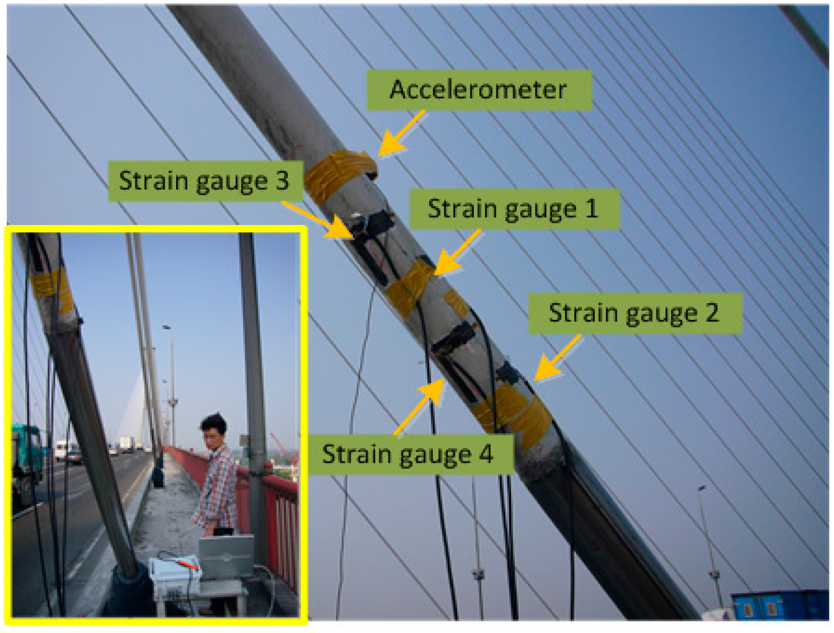
Although the polyethylene (PE) sheathing of the stay cable in a cable-stayed bridge is not considered to be load-bearing, the vibration and tensile deformation of the cable causes the outer HDPE layer to experience axial strains of random amplitude. To obtain accurate sheathing strain level data, tests were conducted for the PE sheathing strain level of the cables of a cable-stayed bridge in service in Shanghai. The bridge is a double-tower double-plane cable-stayed bridge with a length of 1074 m and a main span of 590 m. The entire bridge consists of 240 stay cables. The test was conducted during regular bridge operating hours, and the HDPE sheathing of six stay cables underwent strain tests. The strain data was continuously collected at a sampling frequency of 128 Hz using a DH5920 dynamic data acquisition system. The duration of data collection was 1800 s for cable 1 and 2, and 1200 s for the rest of the cables.
Figure 1 shows a picture of the on-site measurement and the sensor positions of the measurement sites, with strain gauge 1 and 2 located at a height of 2.2 and 2.0 m, on the upside of each cable; and strain gauge 3 and 4 located at a height of 2.3 and 2.1 m, on the downside of each cable.
The test results (see
Table 1) indicate that for the cables tested in this study, the maximum real testing strain amplitude is between 50 and 143.54 με and its mean strain is between 25 and 45 με. These levels are consistent with the theoretical analysis results. The dominant strain amplitude frequency is between 0.2 and 4 Hz.
Figure 1.
On-site strain measurement from HDPE cable sheathing.
Figure 1.
On-site strain measurement from HDPE cable sheathing.
Table 1.
Real fatigue load parameters for six tested cables.
Table 1.
Real fatigue load parameters for six tested cables.
| Cable number | Mean strain amplitude (με) | Maximum strain amplitude (με) | Elastic modulus (MPa) | Stress amplitude (MPa) |
|---|
| 1 | 30.01 | 63.98 | 150 | 9.60 × 10⁻³ |
| 2 | 29.20 | 56.40 | 150 | 8.46 × 10⁻³ |
| 3 | 29.67 | 50.93 | 150 | 7.64 × 10⁻³ |
| 4 | 35.25 | 143.54 | 150 | 21.53 × 10⁻³ |
| 5 | 38.11 | 89.24 | 150 | 13.39 × 10⁻³ |
| 6 | 42.23 | 80.40 | 150 | 12.06 × 10⁻³ |
In an engineering setting, material flaws that occur during production, transportation, installation, or normal operation of cables are unavoidable. These flaws may include air pockets, inanition, unevenness, and cracks. Such flaws usually become the locations at which fatigue damage initiates. Because of the strain concentration phenomenon, the strain levels in the areas of flaws are much greater than those areas in which the material is uniform. Therefore, it is estimated that the strain levels in flawed areas of cable HDPE sheathing may exceed the values shown in
Table 1 by a hundred-fold or even a thousand-fold.
3. Cable HDPE Material Fatigue Testing
As mentioned previously, the PE material in cable sheathing can experience fatigue damage because of the effect of repeated strain. Therefore, we conducted aging and fatigue testing for sample HDPE specimens with fatigue properties consistent with those of the PE material used on cables. An accelerated artificial atmospheric aging experiment use simulated and intensified climatic factors of the atmosphere (e.g., sunlight, temperature, rainfall, humidity, etc.), which can produce results similar to those from a natural atmospheric aging test in a much shorter time frame. Xenon lamp artificial atmospheric aging tests were performed on specimens divided into five groups. The specimens in four of the groups were placed in the aging box and subjected to 5044, 10,088, 15,122, and 20,166 h of artificially accelerated aging under xenon lamps. The last group of specimens did not undergo aging and were used for comparison. After the aging tests were completed, three specimens were taken from each of the five groups. These selected specimens made up three new fatigue test specimen groups, each consisting of five specimens at various stages of aging.
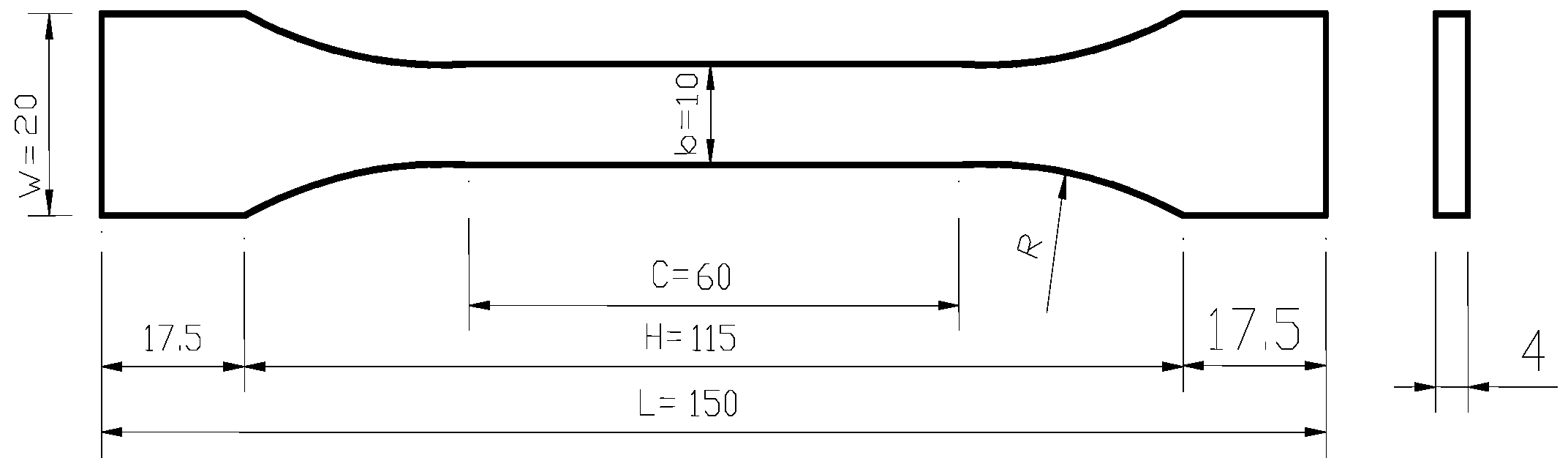
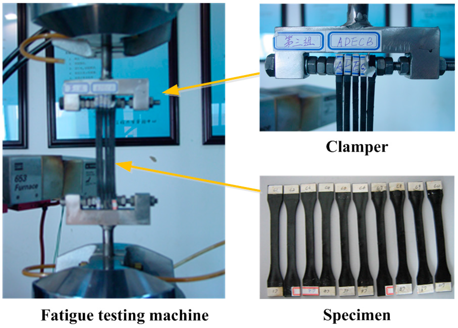
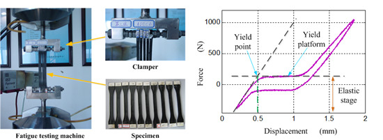
Fatigue tests were conducted on the MTS880 testing machine of the Engineering Mechanics Experiment Center of Shanghai Jiao Tong University. To accelerate the testing process, customized fixtures were used to conduct fatigue testing of five specimens simultaneously. The shape and dimensions of the PE specimens used in the test are shown in
Figure 2. The testing device and selected specimens’ photographs are shown in
Figure 3.
Figure 2.
HDPE Fatigue test sample dimensions.
Figure 2.
HDPE Fatigue test sample dimensions.
Figure 3.
HDPE Fatigue test and some sample photographs.
Figure 3.
HDPE Fatigue test and some sample photographs.
Displacement control and cyclic loading were used in the fatigue tests. To accelerate the testing, conducted using sine loading, the loading frequency was set at the upper limit of the dominant cycle obtained from investigation of real in-service cables. Test data (including the time, displacement, and force) were recorded for 30 cycles from the start 50 cycles of the test, with 256 data points collected for every cycle. Then, every 500,000 cycles the same length of data is recorded.
A different displacement level was used for each specimen group. This was done to study the change in the material’s mechanical properties after a certain number of cycles under the effects of cyclical strain. Based on the analysis mentioned earlier, the strain amplitude was as indicated in
Table 2, depending on the estimated value of the fatigue strain amplitude at the fatigue center areas. The specimens, divided into three groups of five specimens each, were secured using the customized fixture and placed in the MTS fatigue testing machine. A total of 2,000,000 load cycles was applied to each group.
Table 2.
HDPE fatigue testing conditions.
Table 2.
HDPE fatigue testing conditions.
| Group Number | Strain amplitude | Sample fixture distance (mm) | Displacement amplitude (mm) | Test amplitude (mm) | Test strain |
|---|
| 1 | 0.0128 | 130 | 1.65 | +0.2 to +1.86 | 0.0015 to 0.0143 |
| 2 | 0.0096 | 130 | 1.25 | +0.41 to +1.66 | 0.0032 to 0.0128 |
| 3 | 0.0053 | 130 | 0.69 | +0.69 to +1.38 | 0.0053 to 0.0106 |
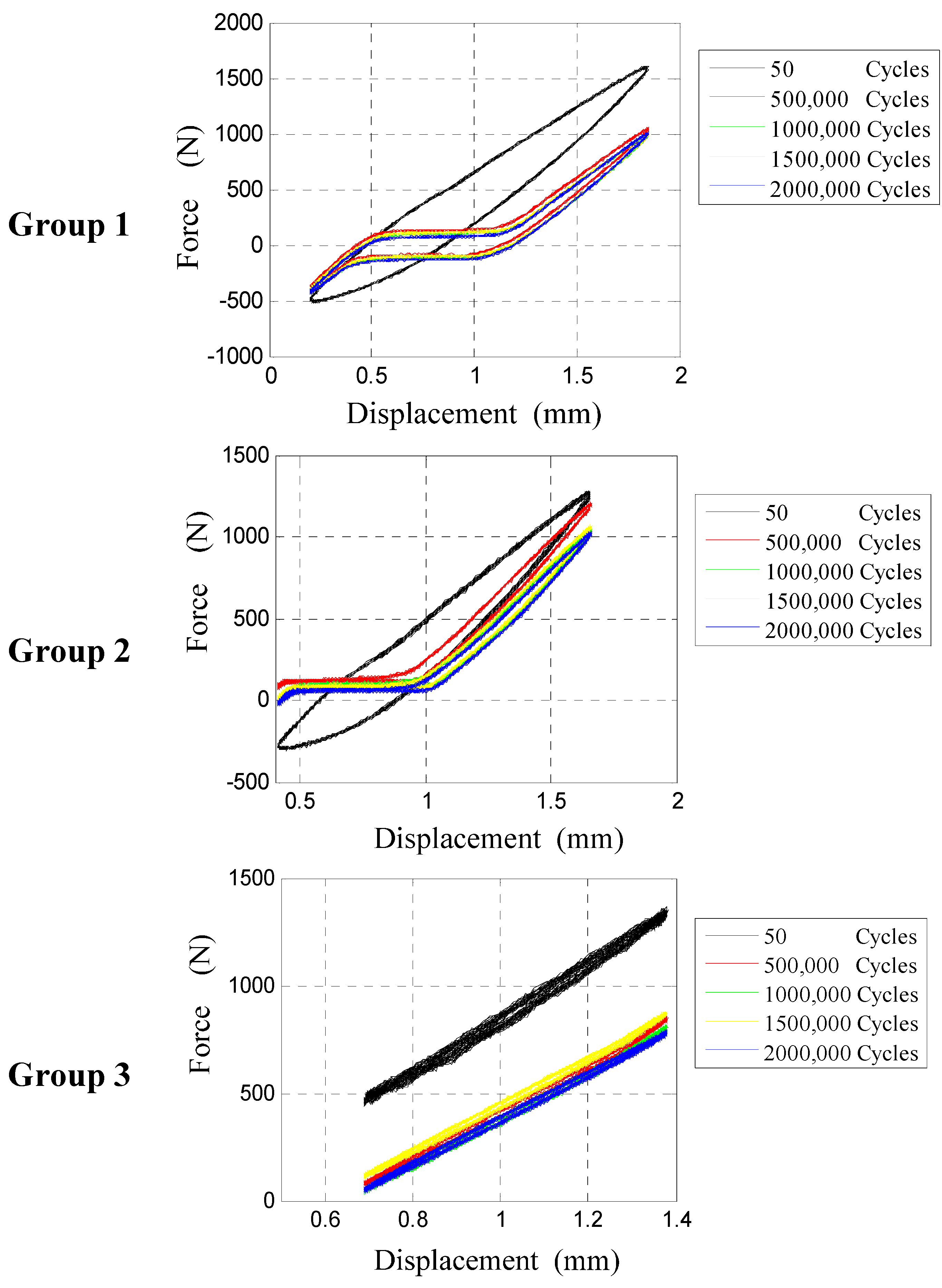
After 2,000,000 cycles of loading for each of the three groups, the three sets of displacement hysteresis curve shown in
Figure 4 were obtained. As the figure shows, the hysteresis properties of the three sets of HDPE specimens all exhibit notable changes as the number of fatigue loading cycles increases. Regardless of the strain amplitude, as the number of cycles increases, the hysteresis area decreases, and the centroid of the area of the closed portion of the hysteresis curve gradually shifts downward. For the two groups with the greater strain amplitude (groups 1 and 2), after a certain number of cycles, the middle sections of the loading and unloading paths of the hysteresis curves both exhibit horizontal platform. For group 1, for which the amplitude was greater, the two paths maintain a greater distance and remain separate, whereas for group 2, for which the amplitude was smaller, the lower and central platform areas of the paths almost coincide. For group 3, for which the strain amplitude was the smallest, both the upward and downward movements of the hysteresis curve exhibit linear growth trends and almost coincide where the hysteresis area approaches zero.
Figure 4.
Three sets of fatigue test displacement hysteresis curves.
Figure 4.
Three sets of fatigue test displacement hysteresis curves.
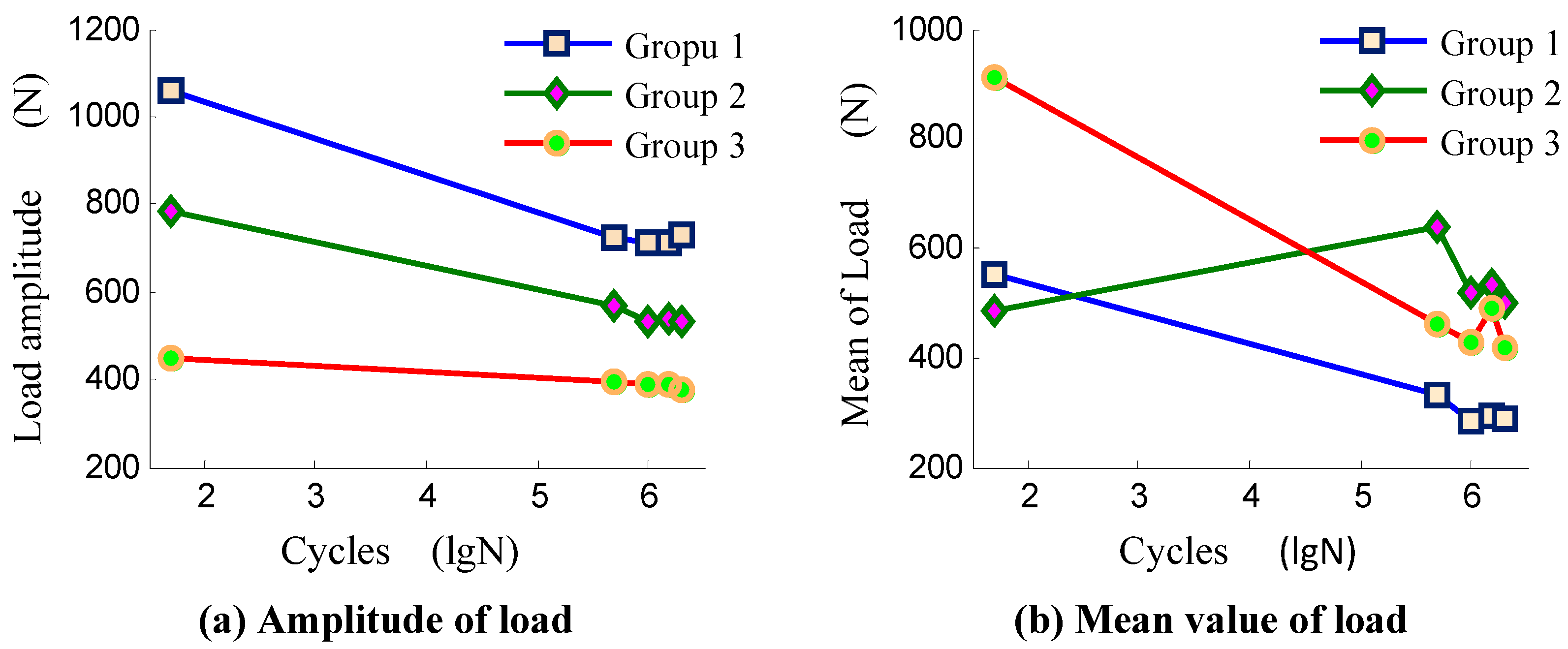
Analysis of the strain levels showed that when the strain amplitude was greater (for groups 1 and 2), pressure stress is occurs in the loading and unloading paths, and its value exhibits a decreasing trend when the fatigue period increased. Following the increase in the fatigue period, the load amplitude and mean load for each group both exhibit decreasing trends, as shown in
Figure 5.
Figure 5.
The change in cyclic force exerted during the displacement-controlled fatigue testing process.
Figure 5.
The change in cyclic force exerted during the displacement-controlled fatigue testing process.
During the 2,000,000 cycles of fatigue loading, none of the specimens exhibited cracks. After the fatigue testing was completed, specimens from the different groups were subjected to static tensile testing at a loading speed of 100 mm/min to determine the static yield strength
fy and elongation at breaking ρ. The results are shown in
Table 3.
Table 3.
HDPE tensile performance after aging and fatigue tests.
Table 3.
HDPE tensile performance after aging and fatigue tests.
| Group | Group 0 | Group 1 | Group 2 | Group 3 |
|---|
| Items | fy (MPa) | ρ (%) | fy (MPa) | ρ (%) | fy (MPa) | ρ (%) | fy (MPa) | ρ (%) |
|---|
| A | 20.60 | 60.70 | 20.38 | 59.16 | 20.35 | 59.52 | 21.47 | 55.28 |
| B | 21.08 | 60.14 | 20.36 | 59.89 | 21.28 | 57.57 | 21.46 | 53.39 |
| C | 21.96 | 62.05 | 20.73 | 62.30 | 21.11 | 60.50 | 21.70 | 52.09 |
| D | 21.11 | 60.50 | 20.37 | 65.36 | 21.40 | 58.94 | 21.01 | 50.98 |
| E | 21.27 | 63.96 | 19.86 | 62.96 | 21.36 | 55.94 | 20.90 | 50.98 |
From the results shown in
Table 3 it is evident that for the specimens subjected to different degrees of aging and 2,000,000 fatigue load cycles at strain amplitudes of 0.0128, 0.0096, and 0.0053, respectively, the changes in the material’s static yield strength were not large and were mostly between 20 and 22 MPa. The elongation at breaking of the material was not changed much (mostly between 55% and 65%). This indicates that neither the aging nor the fatigue testing influenced the static yield strength of the HDPE specimens.
4. Phenomena Observed in Fatigue Testing: Yield Fatigue Effect and Its Parametric Description
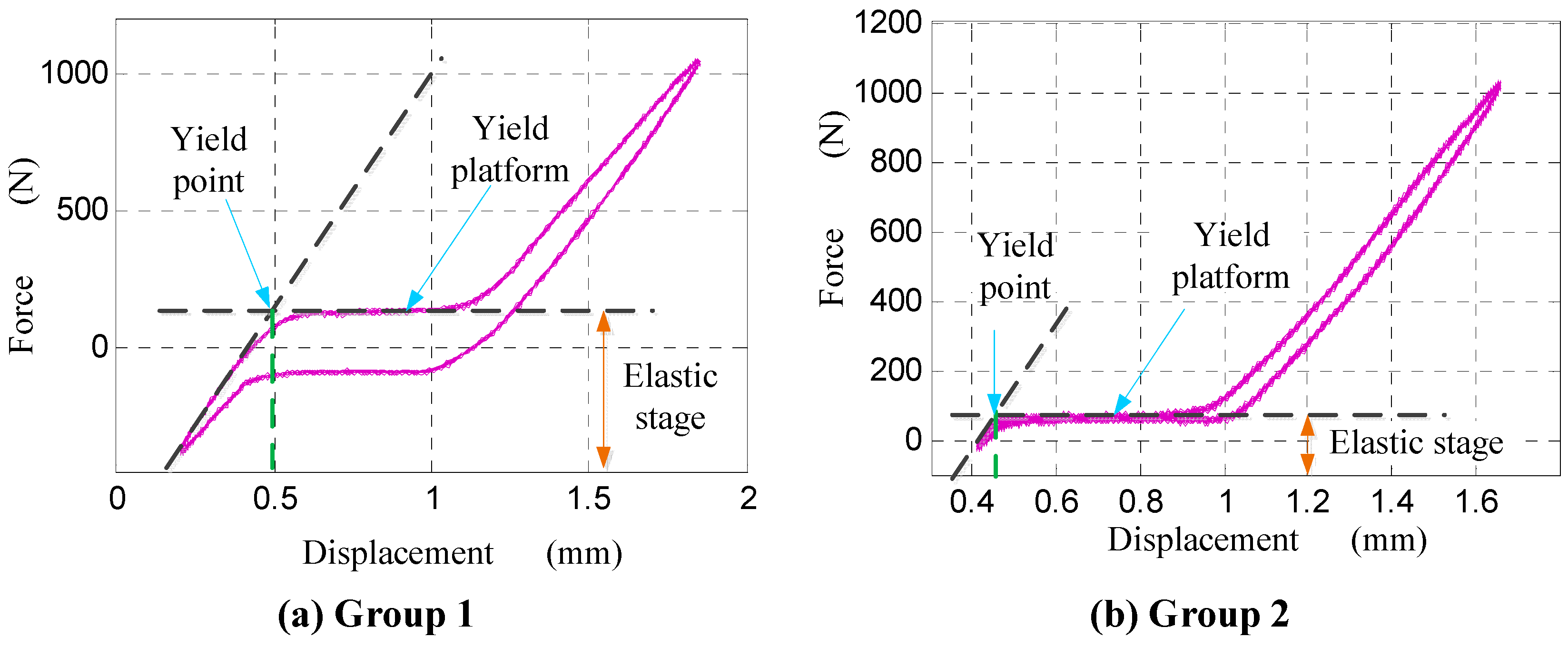
In the fatigue tests discussed in the previous section, the loading and unloading paths of the force–displacement hysteresis curves for groups 1 and 2 after 500,000, 1,000,000, 1,500,000, and 2,000,000 cycles of fatigue loading exhibited evident yield platform and linear growth before entering the platform, with the force-displacement relationship be elastic in form, as shown in
Figure 6.
Figure 6.
Fatigue yield strength and fatigue elastic modulus.
Figure 6.
Fatigue yield strength and fatigue elastic modulus.
Although this type of yield phenomenon is similar to the static loading process, it occurs along the loading and unloading paths of the hysteresis curve. Therefore, this yield phenomenon occurring under fatigue load was defined in this study as fatigue yield, and the elastic period before the yield platform was defined as the fatigue elastic period. The corresponding specimen tension stress was defined as the fatigue yield strength, and the slope of the elastic period was defined as the yield elastic modulus. The intersection between the elastic period and the yield platform is the fatigue yield point. With regard to the situation in which the strain amplitude is small (group 3) and a yield platform does not occur, a specimen can be considered to not have experienced fatigue yield.
Table 4 provides the HDPE fatigue elastic modulus, fatigue yield strength, and fatigue yield strain values obtained from the hysteresis curves.
Table 4.
HDPE fatigue elastic modulus, fatigue yield strength, and fatigue yield strain.
Table 4.
HDPE fatigue elastic modulus, fatigue yield strength, and fatigue yield strain.
| Group | Cycles | Fatigue Elastic Modulus (MPa) | Fatigue yield strength (MPa) | Fatigue yield strain (με) |
|---|
| 1 | Static | 1195.819 * | 20.34 * | 3.226 × 10⁵ * |
| 50 | NA | NA | NA |
| 500,000 | 1133.619 | 0.6433 | 3.696 × 10³ |
| 1,000,000 | 1103.694 | 0.5774 | 3.786 × 10³ |
| 1,500,000 | 1100.628 | 0.5281 | 3.743 × 10³ |
| 2,000,000 | 1092.747 | 0.3034 | 3.606 × 10³ |
| 2 | Static | 1089.737 * | 21.1 | 1.467 × 10⁵ * |
| 50 | NA | NA | NA |
| 500,000 | 1042.889 | 0.6402 | 3.437 × 10³ |
| 1,000,000 | 1009.125 | 0.5062 | 3.609 × 10³ |
| 1,500,000 | 993.885 | 0.4658 | 3.549 × 10³ |
| 2,000,000 | 946.833 | 0.3502 | 3.515 × 10³ |
As
Table 4 shows, the two groups of tests did not produce the fatigue yield phenomenon at the 50th cycle. The yield strength, elasticity modulus, and yield strain values from the static tensile tests are listed for comparison with the static mechanical properties of the HDPE material. These data were obtained from the static tensile tests after the specimens underwent fatigue testing. The data shown in the table are the mean values for the five specimens in each group. It is evident from the data shown in
Table 4 that the fatigue yield strength is much lower than the static yield strength: the former is 1/32 of the latter. The fatigue yield strain is approximately 1/113 of the static yield strain. The fatigue elastic modulus is slightly smaller than the static elastic modulus. Furthermore, as the number of cycles increases, the fatigue elastic modulus, fatigue yield strength, and fatigue yield strain all decrease significantly. Because this experiment recorded relatively few data points, further research is needed to obtain more data points to further explore the patterns of these physical properties as the number of cycles increases.
For macromolecular materials, the strain rate has a significant effect on the material’s mechanical properties.
Table 5 provides estimates for the strain rate for the three test cases.
Table 5.
Strain rate estimates in the HDPE fatigue tests.
Table 5.
Strain rate estimates in the HDPE fatigue tests.
| Group | Strain amplitude | Strain rate (ε/s) |
|---|
| 1 | 1.28 × 10⁻² | 0.0512 |
| 2 | 9.60 × 10⁻³ | 0.0384 |
| 3 | 5.30 × 10⁻³ | 0.0212 |
Although the fatigue strain amplitude of the third group was greater than the minimum fatigue yield strain of the first and second (3.437 × 10
−3, see
Table 4), the third group of testing did not produce fatigue yield points. One possible explanation for this is that, under cyclic loading, the occurrence of fatigue yield of HDPE is dependent on not only the number of fatigue cycles but also the strain rate. The results of the testing show that when the strain rate is small, the yield phenomenon does not occur under fatigue loading, but when the strain rate is large, the fatigue yield phenomenon occurs. It is also possible to infer the existence of a threshold value of strain rate below which the fatigue yield phenomenon will not occur and above which it will. The experimental data indicate that this threshold is between 0.0212 and 0.0384. The experimental data also indicate that when the strain rate exceeds this threshold value, the effect of the strain rate on the change in the fatigue yield strength is negligible.
5. Explanation of HDPE Fatigue Test Mechanics
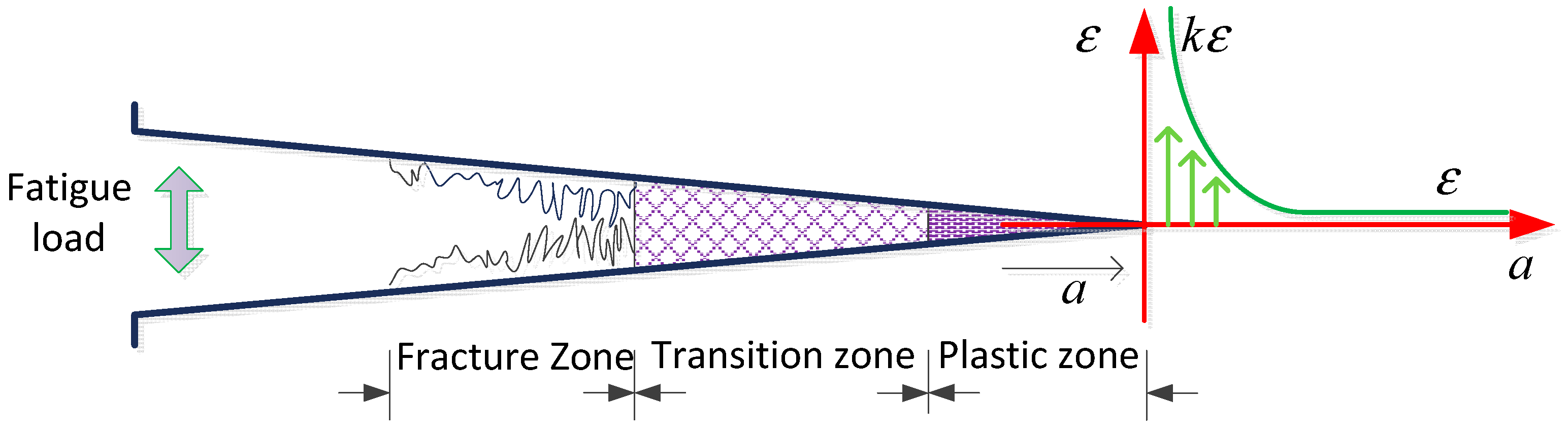
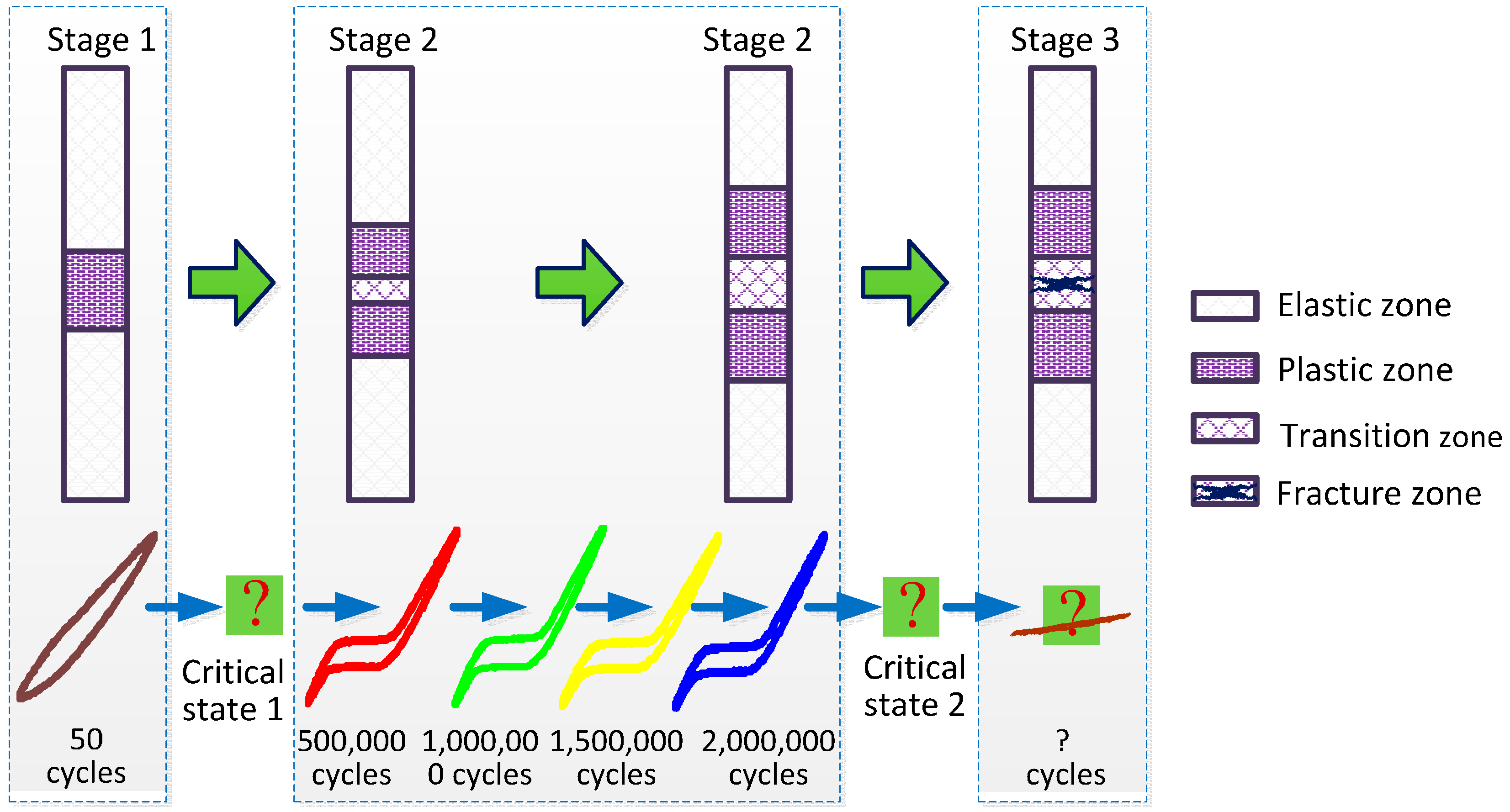
HDPE is a typical polymer for which fatigue failure is a complex and multistage process of accumulation of damage. This process includes, at the microscopic level, the slipping and unraveling of the molecular chain; at the medium level, the formation and nucleation of minute fatigue cracks, followed by the formation, growth, and fracturing of crazing and the shear zone; and at the macro level, the growth of micro cracks to form main cracks (the short crack expansion stage) and the expansion of the main cracks until they are fractured. This process is accompanied by the mutual usage and competition of the crazing and the shear zone. The fracturing of the HDPE material can be divided into three zones: the plastic zone, the transition zone, and the fracture zone at the front of the crack. The appearance and growth of cracks occurs in the plastic zone. The transition zone is mainly contains the shear zone. The creation and development of macro-cracks occurs in the fracture zone.
In the tensile fatigue tests conducted in this study, the fatigue yield phenomenon that occurred at large strain amplitudes can be explained by the following stages, illustrated in
Figure 7:
Stage 1: Elasto-plastic stage. When the number of cycles is low, micro cracks are dispersed on the entire specimen body; the distribution density of these micro cracks is highest in the central area. Loading and unloading paths form the closed hysteresis curve, which surrounds a large, flat area where the micro crack density slowly increases as the number of cycles increases especially in the center, where micro cracks are denser and more numerous than in other areas, forming the plastic zone. The increase in the number of cycles indicates the reaching of threshold state I, when the micro crack in the center slips, intersects, and dislocates, forming a tightly woven shear zone, then the transition zone forms at the center of the plastic zone, generating even larger shearing and distortion (expressed as the tensile deformation of the specimen). At a macro level, the specimen starts to take on the fatigue yield phenomenon;
Stage 2: Fatigue yield stage. In this stage, the plastic zone expands continuously, while new shear zones form and gradually expand inside the nuclear area. This increases the potential for larger shearing deformation while decreasing the required shearing force. Eventually, threshold state II is reached when the shear zones at the nucleus begin to crisscross and subsequently lose the shearing force between materials, inducing the formation of fatigue cracks;
Stage 3: Fatigue crack stage. In this stage, the fatigue cracks widen and lengthen continuously, eventually severing the specimen.
Figure 7.
Medium-level explanation of PE samples under cyclical loads.
Figure 7.
Medium-level explanation of PE samples under cyclical loads.
The entire process encompasses two threshold states, the first corresponding to the fatigue yield threshold state and the second corresponding to the fatigue damage state. Based on these two states, it is possible to perform further fatigue tests to study the corresponding SN curve (stress-number of cycles) and YN curve (yield-number of cycles). Although the tests conducted in this study did not monitor these two states accurately, a comprehensive examination of the basic principles of the fatigue behavior of HDPE material was accomplished.
If the HDPE material used for cable sheathing contain initial flaws or have cracks due to other stages, this will lead to the concentration effect on stress. As illustrated in
Figure 8, under cyclical loading, even if the stress level is very low at locations without fractures and is incapable of causing fatigue yield prematurely, the magnified mean strain level and strain amplitude at the ends of fractures can lead to fatigue yield. In addition, when cracks exist, the ends of the shear zones in the transition zone do not bear forces equally, which makes it easier for the cracks to develop into fatigue fractures under cyclical loading. Therefore, fatigue yield will quickly develop into fatigue cracks that will progress until the material fails.
Figure 8.
Illustration of strain concentration surrounding an initial fracture.
Figure 8.
Illustration of strain concentration surrounding an initial fracture.
Because the stay cable is the key load-bearing component of a cable-stayed bridge structure, the durability of the cable sheathing directly affects the durability of the entire bridge. During construction, actions such as transportation, lifting, and stretching can easily cause initial damage to HDPE sheathing. It is also possible that during a bridge’s operations, it may be damaged by pedestrians, vehicles, maintenance, and even measuring instruments. Even if timely repairs are made, hidden risks still exist at the site of damage due to strain concentration. Therefore, in actual engineering situations, the possibility of HDPE sheathing undergoing fatigue yield under large strain amplitudes is extremely high. Based on these considerations, it is suggested that in durability design, assessment, and protection, the fatigue yield condition should be considered the maximum fatigue durability state for the cable.
6. Conclusions
HDPE materials are often used in bridge construction in the form of metal component sheathing for protection against corrosion. Because of construction requirements, the HDPE sheathing is normally closely connected to the interior metal wires. Therefore, during bridge operations, the HDPE sheathing will unavoidably experience repeated cyclical stress. Through fatigue testing, the mechanical properties of HDPE material under repeated cyclical loading was examined in this study. The results indicate that under the effects of large strain amplitudes and repeated loads, commonly used HDPE materials exhibit clear hysteresis characteristics in their force-deformation behavior. In addition, as the number of fatigue cycles increases, fatigue yield phenomena occur, and evident yield platform effects appear on the loading and unloading paths. To describe these phenomena, parameters such as the fatigue yield strength, fatigue yield strain, and fatigue elastic modulus were defined, and the test results indicate that the fatigue yield behavior of HDPE materials and its descriptive parameters are closely related to the number of cycles, the strain amplitude, and the strain rate.
Because the HDPE sheathing for stay cables is subjected to cyclical strain during use and may have various material flaws and localized damage, the risk of cable sheathing exhibiting fatigue yield and even failure is increased. To increase the durability of cable sheathing, it is suggested that the cable’s fatigue yield condition be considered the maximum fatigue durability state in durability design, assessment, and protection of a cable-stayed bridge. From a view of the bridge maintenance and management, this suggestion will ensure the whole bridge’s safety and durability, although it is conservative for the reason that after the failure of outer HDPE tube, other protections (grouting, individual sheathing of cables, galvanization) can succeed to protect the inner metal wires. Further researches on the fatigue properties of HDPE, not only its SN curve but also its YN curve, are needed.


