Article

Epoxy Enhanced by Recycled Milled Carbon Fibres in Adhesively-Bonded CFRP for Structural Strengthening

1
Department of Civil Engineering, Monash University, Clayton, VIC 3800, Australia
2
The Key Laboratory of Civil Engineering Safety and Durability of China Education Ministry, Department of Civil Engineering, Tsinghua University, Beijing 100084, China
*
Author to whom correspondence should be addressed.
Polymers 2014, 6(1), 76-92; https://doi.org/10.3390/polym6010076
Submission received: 27 November 2013 / Revised: 18 December 2013 / Accepted: 19 December 2013 / Published: 31 December 2013
(This article belongs to the Special Issue Selected Papers from "SMAR 2013")

Abstract

:
This paper investigates the mechanical performance and electrical resistivity of a structural adhesive epoxy enhanced using milled carbon fibre (MCF) as well as the bond performance of carbon fibre reinforced polymers (CFRP) and steel adhesively bonded joints using the enhanced epoxy. The epoxy was enhanced using such MCFs with different weight ratios of 1.5%, 3% and 5%. Tensile experiments were performed on the original and enhanced epoxy specimens according to ASTM D638. More ductile process failure was found for the epoxy after modification and significant improvements of E-modulus and tensile strength were evidenced when the MCF weight ratio was larger than 1.5%. Scanning electron microscopy (SEM) revealed that the failure mechanism of short MCFs pulled out from the epoxy matrix contributed to the enhancement of the mechanical performance of the epoxy. The electrical resistivity of the epoxy with MCF weight ratio of 5% was reduced by at least four orders of magnitude compared to the original epoxy, due to the conductive network formed by MCFs. Steel/CFRP double strap joints (with either CFRP sheets or CFRP laminates) were prepared using the enhanced epoxy and then tested in tension, however no obvious increase in joint stiffness or strength was observed.

1. Introduction

Steel structures are susceptible to corrosion and fatigue damages and there is an urgent need to repair and retrofit such deteriorated steel structures. The use of adhesively bonded carbon fibre reinforced polymer (CFRP) composites in strengthening of steel structures may be an advantageous solution, because of the excellent mechanical properties of CFRP such as high strength to weight ratios (with an E-modulus of 240 GPa and nominal tensile strength of 3800 MPa) and excellent resistance to corrosion and fatigue. In addition, interruption of structural service may be minimized during the strengthening process in this way. The concept of using CFRP in structural rehabilitation was initiated from aerospace engineering in the 1970s [1]. Relevant practices of such a concept in civil engineering are increasing rapidly [2]. Recent studies indicated that combining FRP and steel in different configurations, such as adhesively bonding [3,4] and confining [5,6] may form a reliable load-carrying system and can be utilized in steel structure strengthening in a safe and economic manner.
In such strengthened systems, CFRP composites are externally bonded to steel members, therefore the structural adhesive used is of a great importance [7,8,9]. Epoxy is a structural adhesive frequently used in strengthening of steel structures and it is reported that failure often occurs through steel and adhesive interface debonding, or adhesive layer failure (cohesive failure) as a result of relatively low strength of epoxy, or delamination of CFRP composites [4,10]. There is a need to improve the mechanical performance of adhesive epoxy through enhancement of certain mechanical properties using appropriate additives without significantly decreasing other ones.
Efforts have been made in the modification of epoxy to achieve better mechanical performance by adding rigid particles such as glass beads, and silica while the results have turned out to be unsuccessful in terms of the improvement of physical bonding [11]. It was found that the toughness of the epoxy was obviously increased by implementing a carboxyl-terminated copolymer of butadiene and acrylonitrile (CTBN). However a decrease of glass transition temperature was observed for such a modified epoxy and therefore not suitable for applications at higher temperature [12]. Recently studies have focused on the introduction of carbon nanotubes (CNT) to modify the epoxy. The integration between CNT and resin matrix has the potential to ameliorate the weaknesses of conventional laminated composites including delamination, lack of impact damage resistance, and low transverse mechanical properties [13]. Compared to original epoxy, improvements in flexural strength, glass transition temperature, and decomposition temperature have been reported [14]. However the demand of high volume and high rate production of CNTs, as well as the associated costs, hinder the applications of CNT-modified epoxy, in large scale particularly in civil infrastructure [15]. Yet, it is a challenge to achieve a high percentage of CNT (especially for single-walled CNT) at the desired level because of dispersion problems [13].
Recycled milled carbon fibres (MCF), on the other hand, present a promising and more practical way to enhance structural epoxy adhesives. MCF refers to a carbon fibre with a length of 1mm or less and much shorter than chopped carbon fibres, which can be recycled from used carbon materials. The traditional solutions of disposal of such carbon fibre waste are to use land-fill or waste incineration [16]. Such solutions represent a waste of natural resources and, considering the fact that carbon fibre does not decompose naturally, environmental issues may well be very critical. Several recycling technologies have been developed to reclaim carbon fibres from CFRP materials used in aerospace and military products for other structural applications [17]. Although the exact recycling process to produce milled carbon fibres was patented [18], it is known that a pyrolysis process is involved [19,20] to burn off the polymer matrix and free the carbon fibres through elevated temperatures.
Although investigations on enhancement of epoxy using chopped carbon fibres indicated an improvement of its toughness up to a fibre volume fraction of 36% [21], studies on the mechanical performance of modified epoxy using MCFs are limited. It was reported that the direct-current (DC) conductivity was improved after the addition of MCFs [22] while the abrasive wear rate of the resulting composite was reduced [23]. Such a MCF enhanced epoxy was made using a centrifugation technique. MCFs were firstly mixed with epoxy resin and hardener and fully stirred with a glass rod and then the sample was placed in a mould and rotated to form a gradient of MCFs [22]. The results from the literature suggest reduced electrical resistance and promising mechanical performance of the MCF enhanced epoxy. However, adhesively-bonded systems using MCF enhanced epoxy have not been reported yet.
In this paper, MCFs were used to enhance an epoxy and the resulting epoxy was used to prepare a steel/CFRP adhesively-bonded system in a form of double strap joints. Different percentages of weight ratio of MCFs were investigated in the epoxy specimens and joint specimens. Both specimens were tested in tension to examine the mechanical properties such as stress-strain response, E-modulus and ultimate load. Failure modes were identified and discussed with respect to the effects introduced by the addition of MCFs. In addition, scanning electron microscopy (SEM) was used to understand the changes of mechanical performance after introducing MCFs to the epoxy and steel/CFRP adhesively-bonded joints. Finally, the electrical resistivity of the MCF modified epoxy was tested as a preliminary study for its potential application in health monitoring of a FRP/steel bonding system.

2. Experimental Investigations

2.1. Materials

Araldite 420 epoxy was used for MCF addition and was used as the adhesive to prepare the steel/CFRP double strap joints. Araldite420 epoxy (produced by Huntsman Advanced Materials Ltd., Melbourne, Australia) consists of two components 420A (Bisphenol A/epochlorohydrin resin, liquid based epoxy resin) and 420B [Diethylene glycol, di(3-aminopropyl)ether based epoxy resin as hardener]. Previous experiments indicated a nominal tensile strength of 32 MPa, tensile modulus of 1.9 GPa and tensile ultimate strain of 2.4% for the epoxy [24].
The milled carbon fibre (MF100) used to modify the epoxy was recycled and supplied by ELG Carbon Fibre Ltd. (West Midlands, UK). It is with an average particle diameter of 7.5 μm and length of 100 μm. The fibre density was reported as 1800 kg/m3 and the tensile strength and tensile modulus were 3150 and 200 GPa respectively [25].
Both carbon fibre sheet (CF130), and carbon fibre laminate (MBrace 210/3300) were used to prepare steel/CFRP double strap joints. CFRP sheet and laminate were supplied by BASF (Melbourne, Australia). For CFRP sheet (MBrace CF130), the nominal elastic modulus is 240 GPa and its nominal tensile strength is 3800 MPa [26]. For CFRP laminate (MBrace Laminate 210/3300), the nominal elastic modulus is 210 GPa and its nominal tensile strength is 3300 MPa [27]. The steel elastic modulus was measured as 200 GPa and the yield stress and ultimate stress were measured as 359 and 430 MPa respectively [28].

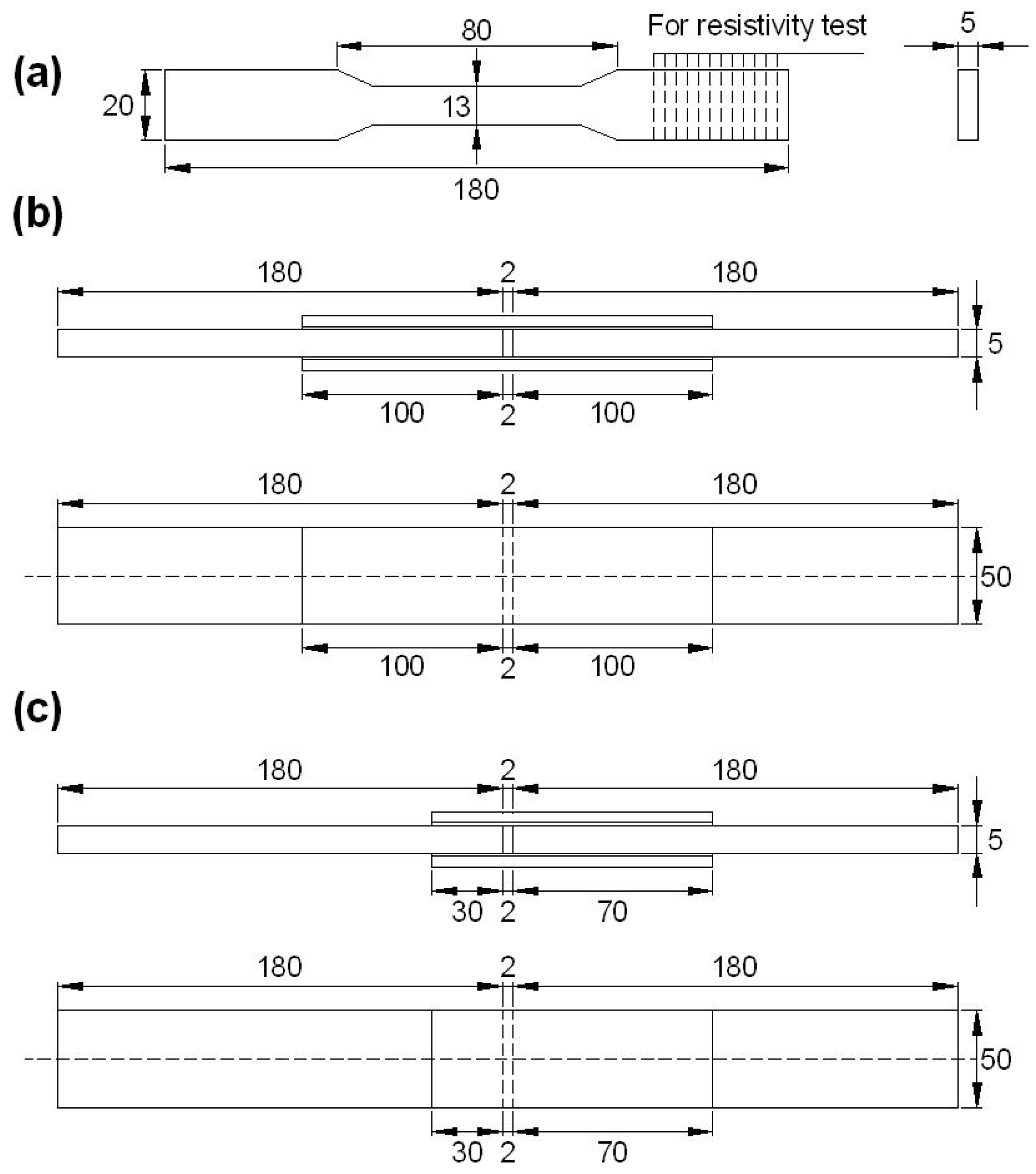
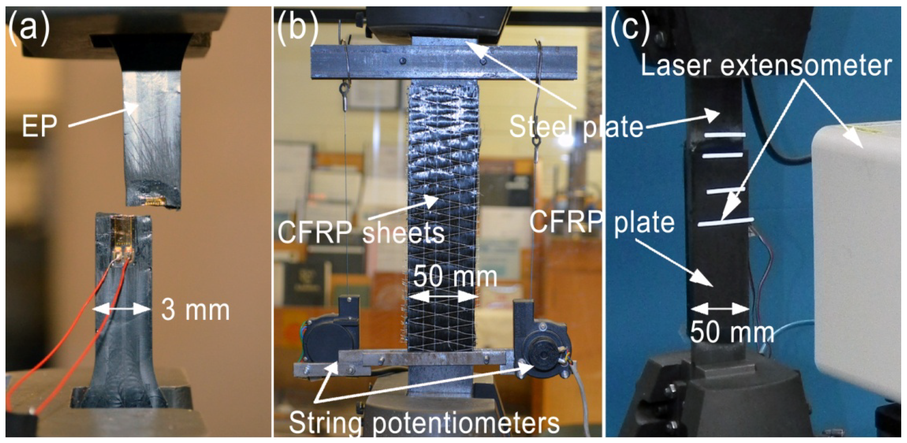
2.2. Mechanical Experiments

Three scenarios were examined in mechanical experiments as summarized in Table 1. Scenario EP investigated the mechanical properties of the epoxy after MCF modification. Dog-bone specimens were prepared with different weight ratios of milled carbon fibres to epoxy (see Table 1). It was suggested that Araldite 420A and 420B should be mixed with a ratio by weight of 100:40 to form the epoxy matrix before application [29]. To achieve sufficient time for mixing and vacuum in order to minimise the amount of bubble in the epoxy, Araldite 420A was first mixed with the MCFs by hand mixing and then placed in the vacuum pump for two days before the addition of hardener 420B. After that, the 420B hardener was mixed by hand mixing into the mixture. This had to be a gentle process otherwise bubble would have been produced and made the vacuum pumping process useless. Once this process was completed, the MCF enhanced epoxy was poured into the mould to form the dog-bone epoxy specimens as shown in Figure 1a, according to the geometry specified in ASTM D638 [30]. The pouring process was as slowly as possible to minimise the formation of air bubble. The MCF enhanced epoxy was left in the mould to cure at room temperature for 10 days according to the manufacturer’s instructions [29]. The specimens without MCF were deep green and became dark black after the MCF addition. Totally, twelve specimens were prepared in this scenario, and therefore three identical specimens (named as EPx-y, where x represents the weight ratio and y is from 1 to 3 as the specimen number) were repeated for each MCF weight ratio. For the EP specimen, the tensile test was performed using an Instron machine (Instron, Melbourne, Australia) with a load capacity of 50 kN. The strain gages with resistance of 120.0 ± 0.3% and gage factor of 2.095 ± 0.5% at room temperature were installed at the centre of the specimens to measure the load-strain developments (see Figure 2a). The specimens were loaded in tension at a displacement control rate of 1 mm/min.
Table 1. Mechanical experiments and key parameters.
ScenariosMaterialsSpecimensWeight ratio of milled carbon fibreCarbon fibre sheet or laminate layers
EP (epoxy)milled carbon fibre, epoxydog-bone coupons0%, 1.5%, 3% and 5%NA
DJS (double strap joints with CFRP sheets)milled carbon fibre, epoxy, CFRP sheet, steel platedouble strap joints0%, 1.5%, 3% and 5%1 and 3
DJL (double strap joints with CFRP laminates)milled carbon fibre, epoxy, CFRP laminate, steel platedouble strap joints0% and 5%1
Scenario DJS investigated the mechanical performance of steel strengthened by CFRP sheets using origin and enhanced epoxies. Double strap joints were prepared in this scenario with different weight ratios of milled carbon fibres. In addition, two fibre sheet layouts—one layer and three layers of CFRP sheets—were used in the joint configuration as shown in Figure 1b. The different fibre sheet layouts were to examine the change of failure modes and the load carrying capacity corresponding to each failure mode, with the existence of milled carbon fibre modification.
Figure 1. Dimensions and configurations for (a) EP specimens; (b) DJS specimens; and (c) DJL specimens (unit in mm, not in scale).
Polymers 06 00076 g001
Figure 2. Experimental setup and instrumentation for (a) EP specimens; (b) DJS specimens; and (c) DJL specimens.
Polymers 06 00076 g002
The joint specimens were prepared using modified epoxy adhesives (with different weight ratios of milled carbon fibre, see Table 1), steel plates and CFRP sheets. Two steel plates with a dimension of 5 mm × 50 mm × 180 mm were used to fabricate the double strap joint, after surface preparation (cleaning and sand-blasting). Then the prepared epoxy was applied on each surface of the steel plate, and one layer of CFRP sheet was placed and then again the same epoxy was applied on its surface or between CFRP layers to form the polymer matrices of the CFRP composite. The resulting specimens are illustrated in Figure 1b where a bond length of 100 mm was used for all the specimens. This bond length was greater than the effective bond length of 40 mm for the one-layer CFRP joints and of 50 mm for the three-layer CFRP joints with identical geometry prepared using original epoxy [28]. The specimens were designated as DJSx-y-z, where x represents the weight ratio of MCF, y is the number of CFRP sheets (1 or 3) and z is the specimen number (1 or 2) in each specified condition.
Scenario DJL was also a double strap joint of steel plates bonded with CFRP laminate. The steel plates had the same dimension as those in scenario DJS, whereas the bond length of CFRP laminate was 30 mm, as shown in Figure 1c. The bond length was chosen shorter than its effective bond length (60 to 70 mm) as reported in [31], to ensure failure occurs because of the adhesive bonding. CFRP on the other side was set at 70 mm so that the failure would occur on the side of the 30 mm bond length. Eight double strap joints were prepared, four of which were with original epoxy, and the other four were with modified epoxy (5% weight ratio of MCF). The preparation process was the same as that in scenario DJS and the specimens were labelled as DJLx-y, where x represents the weight ratio of MCF (0% or 5%), y is the specimen number (1–4).
A Shimadzu Universal Hydraulic Testing Machine (Shimadzu, Melbourne, Australia) was used to test the DJS specimens in tension to failure (see Figure 2b). This testing was carried out at a constant rate of 2 mm/min. Two string potentiometers, LX-PA2 manufactured by Unimeasure, with accuracy of 1.25 × 10⁻³ mm, were used to measure the elongation of a joint region of 205 mm (see Figure 2b), which was then averaged by the readings from the two string potentiometers. The same setup and loading speed were adopted for DJL joints, and a laser extensometer was used to measure the relative slip through the 30 mm bond length (see Figure 2c).

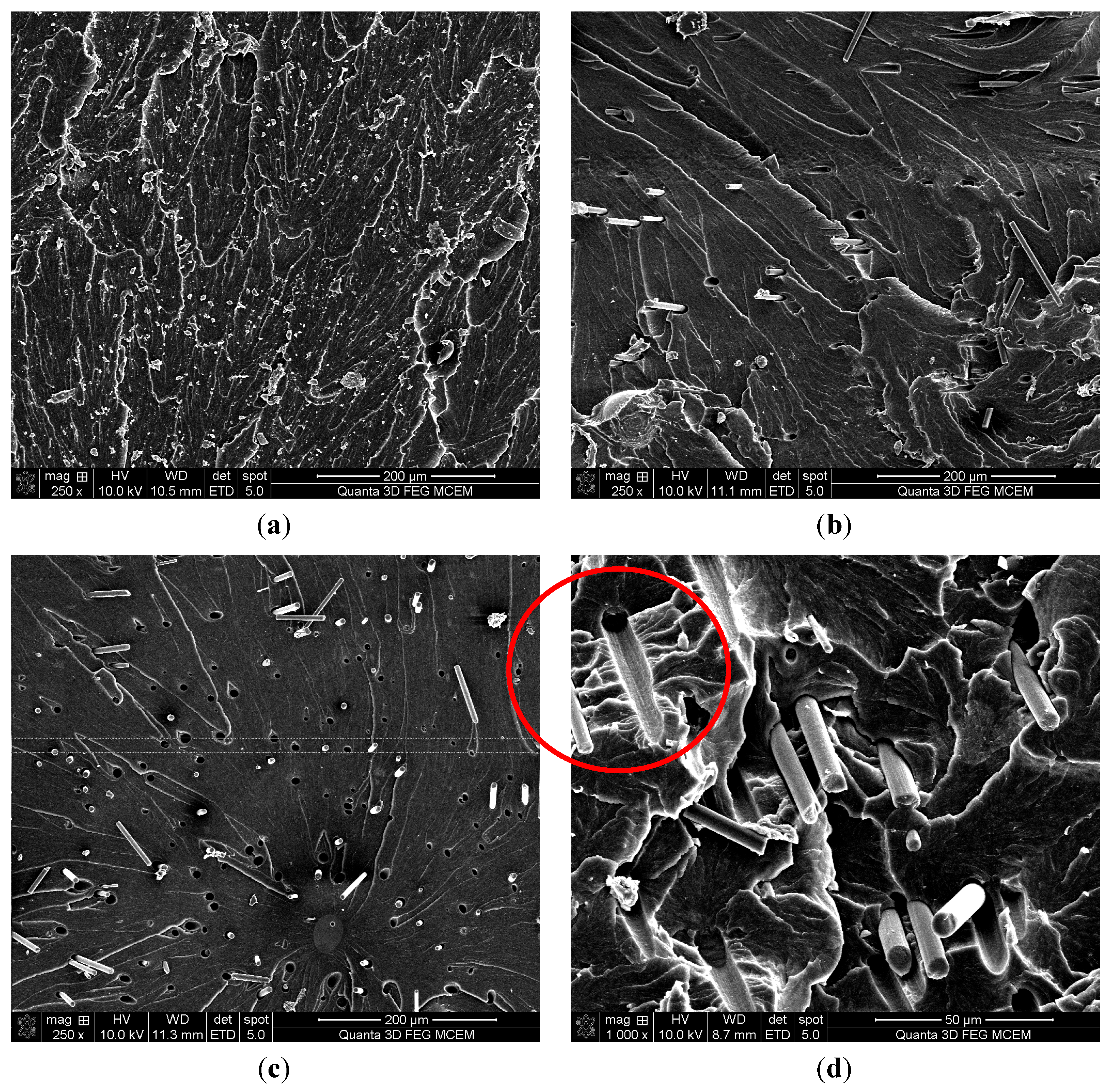
2.3. Scanning Electron Microscopy

SEM was used to observe the microstructure of the epoxy after MCF addition with different weight ratios. The samples used in SEM were cut from the damaged EP specimens after testing and the observation target was the failure surface.
The samples were examined at the Monash Centre for Electron Microscopy, using an accelerating voltage of 10 KV. Different magnifications ranging from 100 to 2500 were adopted for each specimen with different weight ratios (0%, 1.5%, 3% and 5%), in order to identify any differences among them.

2.4. Electrical Resistivity

The electrical resistance (R) of original epoxy and epoxy with 5% weight ratio of MCF was tested using an Agilent 34461A 6½ digit multimeter (Agilent Technologies, Melbourne, Australia). The samples for electrical resistance test were sliced from dog-bone coupons prepared in scenario EP (see Figure 1a) using a diamond saw. Four samples of original epoxy and eight samples of epoxy with 5% weight ratio of MCF were prepared. All samples were in a rectangular shape with a thickness less than 1.5 mm. The detailed dimensions are listed in Table 3. The electrical resistance was measured in the thickness direction. In order to ensure the testing consistency, all samples of the same MCF weight ratio (0% or 5%) were cut from the same dog-bone coupon. Grade 1200 sand paper was used to polish the two sides of each sample. Then all samples were washed in a water bath (constant temperature control of 25 °C) using a horn sonicator (model VCX 500, from Sonics & Materials Inc., Melbourne, Australia) under 30% energy output for 30 min. The purpose was to clean the surface debris from saw cutting and sand paper polishing. The samples were left to dry for 12 h at room temperature. Finally, the two sides of each sample were painted as electrodes using silver conductive paint from RS Components Pty. Ltd. (Melbourne, Australia). After the measurement of electrical resistance (R), the electrical resistivity (ρ) can be calculated by:
ρ = Rab/t
where a, b and t are the length, width and thickness of the rectangular sample, respectively.

3. Results and Discussion

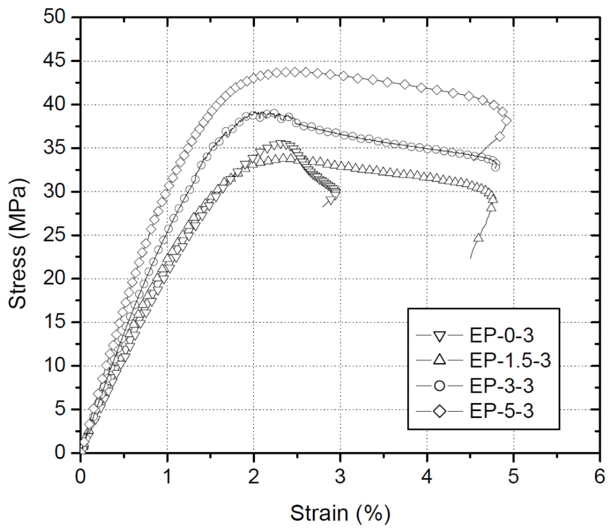
3.1. Results from EP Specimens

All the EP specimens failed in a similar way to the breakage at the middle region of the dog-bone shape as shown in Figure 2a. The stress and strain curves of typical EP specimens with different weight ratios of milled carbon fibre are summarized in Figure 3, where the stress values were calculated using the measured loads divided by the sectional area at the failure position. It can be observed that the slope of the curves at the elastic region (linear part), i.e., the E-modulus, is improved with the increase of the MCF weight ratio, as well as the ultimate stress at failure (i.e., the tensile strength).
Figure 3. Stress-strain curves of typical original epoxy specimen (EP0-3) and enhanced epoxy specimens with different weight ratios of MCFs (EP1.5-3, EP3-3 and EP5-3).
Polymers 06 00076 g003
The detailed values of E-modulus and tensile strength of all the specimens (average values and standard derivations) are summarized in Table 2. The E-modulus of the original epoxy showed an average E-modulus of 2.06 GPa and very similar to the value (1.9 GPa) reported by the manufacturer. The improvement of E-modulus was not obvious (only 6.8%) at the weight ratio of 1.5% of milled carbon fibres while such an improvement became significant (31.1%) when the weight ratio increased to 3%, and became 50.5% when only 5% by weight of MCFs were used to modify the epoxy. More than 5% by weight of MCFs made the specimen preparation very difficult because of the loss of mobility of the epoxy resin. Surfactant may be necessary to prepare the epoxy specimens modified using MCFs with a weight ratio more than 5%.
Table 2. Elastic modulus, strength and ultimate stain of modified epoxy with different weight ratios of milled carbon fibre (values are averages of three identical specimens).
SpecimenWeight ratioE-modulus (MPa)Strength (MPa)
EP0-y0%2.06 ± 0.06 (100%)34.8 ± 1.1 (100%)
EP1.5-y1.5%2.20 ± 0.10 (106.8%)32.8 ± 1.4 (94.3%)
EP3-y3%2.70 ± 0.17 (131.1%)37.3 ± 1.7 (107.2%)
EP5-y5%3.10 ± 0.37 (150.5%)40.1 ± 3.3 (115.2%)
The tensile strength of enhanced epoxy specimens demonstrated similar variation to that of E-Modulus. No improvement was found for the specimens with a weight ratio of 1.5% MCFs but rather a slight decrease (see Table 2). It was believed that the slight decrease of strength for specimens EP1.5-y in comparison to EP0-y in Table 2 was because of data scattering rather than any physical mechanism. Considerable tensile strength enhancement (15.2%) was identified for the specimens EP5-y with a weight ratio of 5% of MCFs.
The strain at the ultimate load of specimens EP0-y was found to be 2.37 ± 0.03% and this value is consistent with that (2.4%) reported previously [24]. Similar but slight smaller strain values at the ultimate loads were found for the other specimens (EP1.5-y, EP3-y and EP5-y) in a range from 2.15% to 2.37% with larger derivations. After the ultimate loads were reached, the strains kept increasing without significant loss of applied stress for the epoxy after MCF addition and this behaviour demonstrated a “yielding” stage in their stress-strain curves, implying that a ductile performance was introduced to the epoxy after MCF addition. As a result, the strains at the final breakage failure were largely improved to be in a range from 3.5% to 4.7% for the MCF enhanced epoxy specimens, in comparison to that (3.0%) for the original epoxy, as also evidenced in Figure 3.

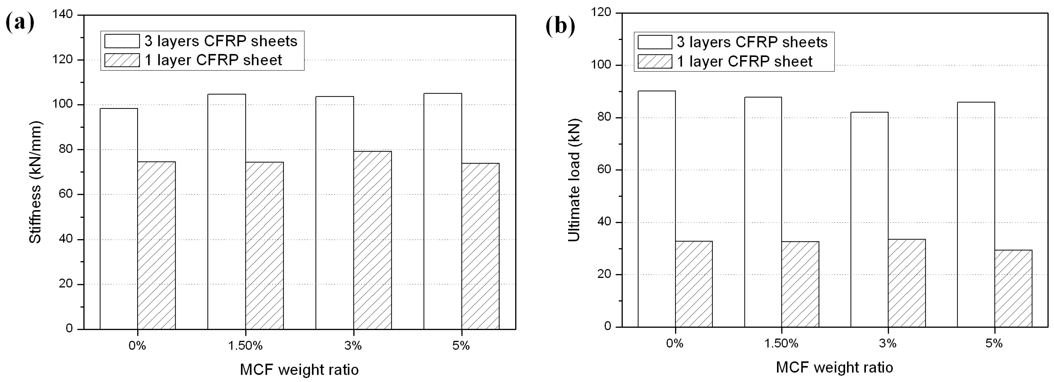
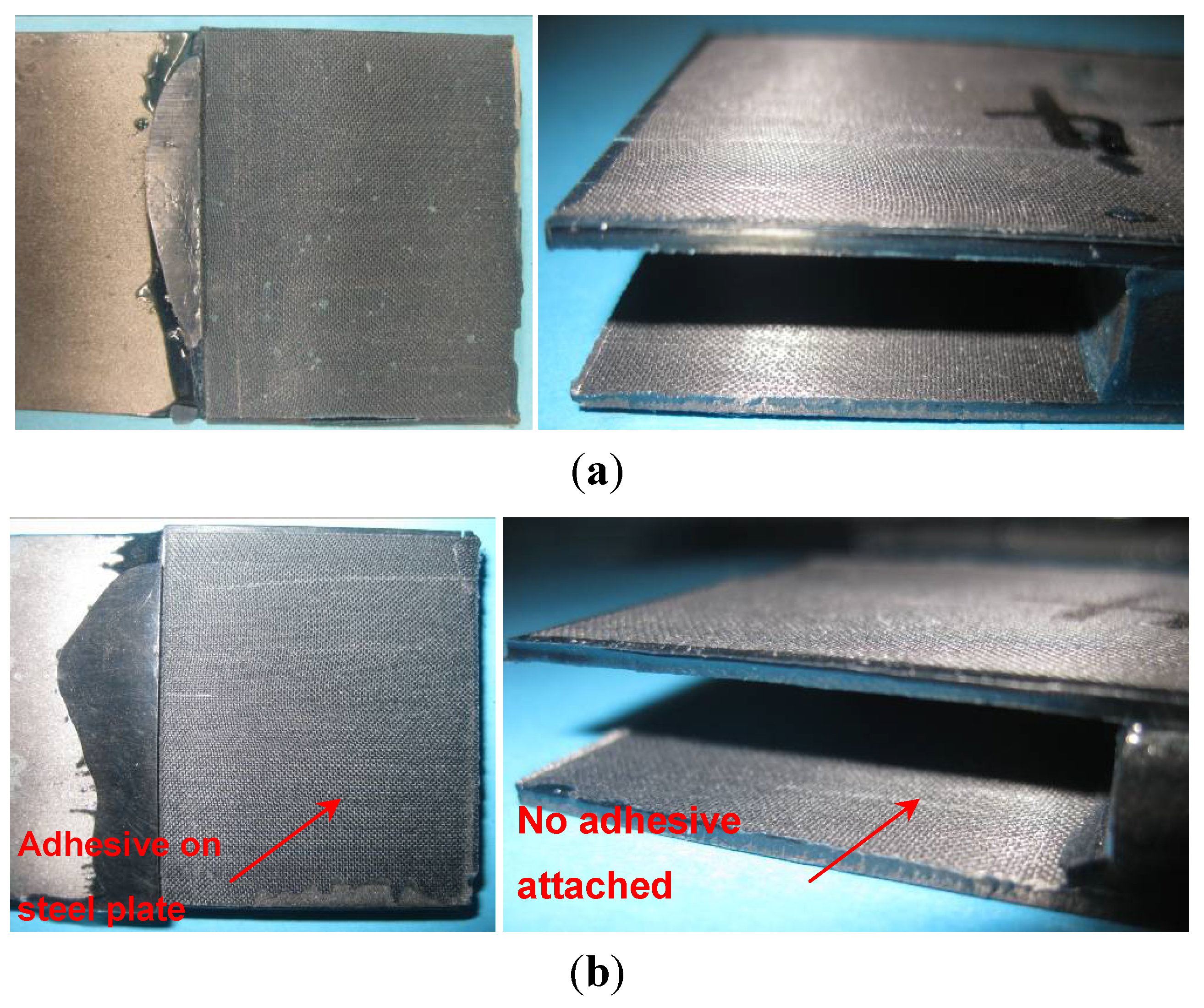
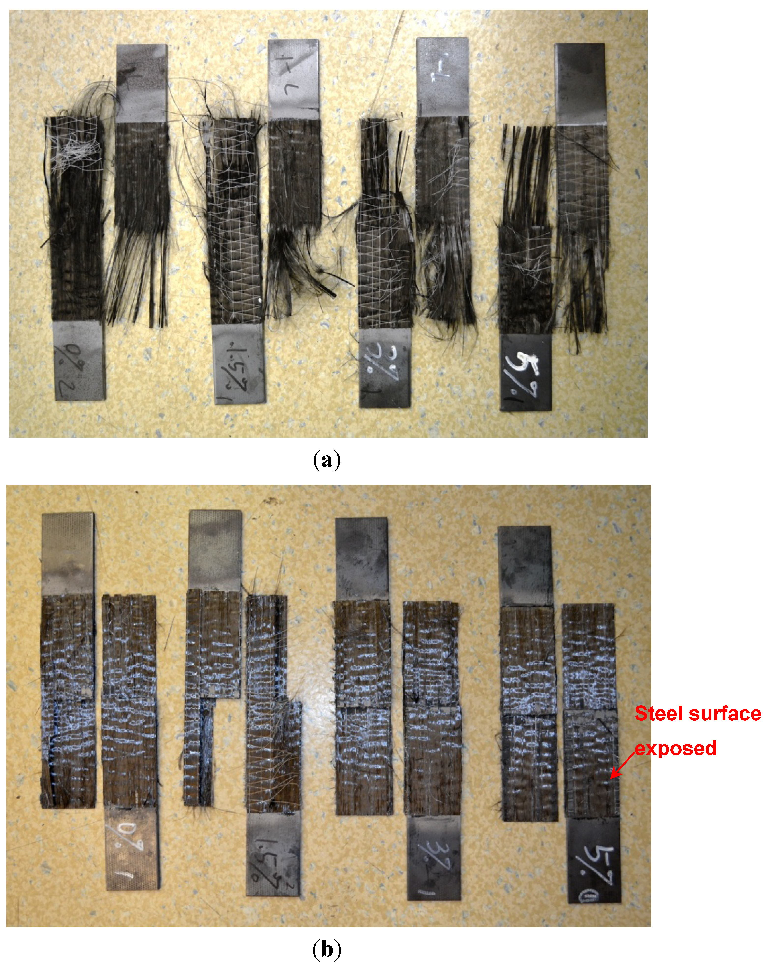
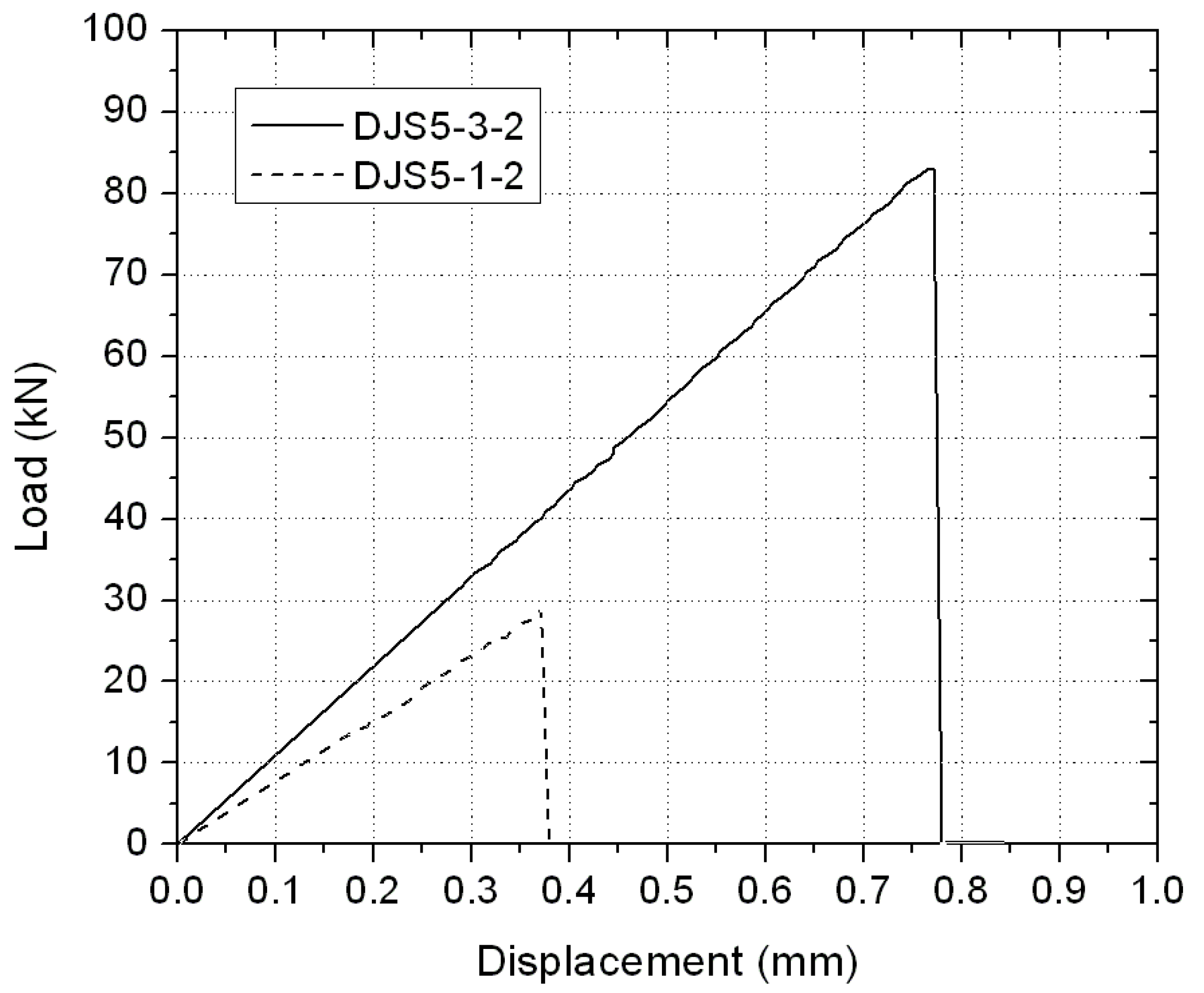
3.2. Results from DJS Specimens

Failed specimens of steel/CFRP double strap joints with one layer of carbon fibre sheet are shown in Figure 4a, where the same failure mode was identified. These joints failed through the delamination of the carbon fibre sheet at the centre of the joints, regardless of the different MCF weight ratios used in the epoxy adhesive. Only part of the carbon fibres was pulled out from the full bond length of 100 mm and the steel surface in the joint region was still covered by most of the carbon fibre sheet. No adhesive interface debonding or cohesive failure was identified and this result suggested that the bonding provided by the epoxy between the carbon fibre sheet and the steel surface was almost intact. The failure modes of steel/CFRP double strap joints with three layers of carbon fibre sheets were shown in Figure 4b. Again all the specimens with three layers of carbon fibre sheets failed mostly through delamination of the layers of carbon fibre sheets, independent of the MCF weight ratios. It was found that the steel surface in the joint region was largely covered by carbon fibre sheet while only a small surface area was exposed for the joints DJ5-3 (see Figure 4b). Such a failure mode may imply that the joint load-carrying capacity is dominated by the interlaminar shear strength of the carbon fibre sheets, rather than the epoxy strength of the adhesive layer.
Typical load displacement curves of DJS joints are shown in Figure 5. All the joint specimens with one or three layers of carbon fibre sheets showed a linear load-displacement development until the final failure. Although the epoxy demonstrated a ductile failure process after MCF addition, such behaviour was not observed for the joints with different MCF weight ratios. This may be attributed to failure mode of delamination, rather than cohesive failure.
Figure 4. Failure modes of DJS specimens with (a) one layer of carbon fibre sheet (DJS0-1, DJS1.5-1, DJS3-1, and DJS5-1); and (b) three layers of carbon fibre sheet (DJS0-3, DJS1.5-3, DJS3-3, and DJS5-3).
Polymers 06 00076 g004
Figure 5. Load-displacement curves for typical DJS specimens.
Polymers 06 00076 g005
The change of joint stiffness with the weight ratio of MCF is shown in Figure 6a and that of joint ultimate load is shown in Figure 6b. No obvious improvement of joint stiffness or joint ultimate load was observed after the MCF addition to the specimens with one and three layers of carbon fibre sheets, again as a result of the delamination failure mode of the carbon fibre sheet. The slight variation of results in Figure 6a,b is due to data scattering rather than any solid physical mechanism.
Figure 6. Comparison of (a) stiffness; and (b) ultimate load of DJS specimens with different MCF weight ratios.
Polymers 06 00076 g006

3.3. Results from DJL Specimens

A shorter bond length of 30 mm in DJL specimens changed the failure mode to adhesive-CFRP laminate interface failure, as shown in Figure 7. It can be seen that, the same interface failure happened for joints with either original epoxy or modified epoxy with 5% weight ratio of MCF. This failure mode explains the similar ultimate failure load and stiffness of all DJL joints. For example, the average measured ultimate load of DJL with 0% MCF was 100.6 kN, compared to 102.0 kN for DJL with 5% MCF. The stiffness of the DJL specimens was calculated from the load-displacement curves of DJL joints, and the average stiffness of DJL with 0% MCF was 854.9 kN/mm, compared to 904.6 kN/mm for DJL with 5% MCF.
Figure 7. Failure modes of DJL specimens with (a) original epoxy adhesive (DJL0-4); and (b) epoxy with 5% MCF weight ratio (DJL5-4).
Polymers 06 00076 g007
Similar double strap joints tests were conducted by Korayem et al. [31], where the epoxy (Araldite 2011) was modified using a 3% weight ratio of multi-walled carbon nanotubes (MWCNT). It was also concluded that no obvious improvement in ultimate load and stiffness was observed due to the fact that little failure occurred in the adhesive layer (CFRP delamination and adhesive/adherent interface failure dominated). Therefore, careful design of double strap joints to achieve adhesive failure (cohesive failure) is necessary to reveal the potential enhanced bond performance of the CFRP/steel system using modified epoxy.

3.4. SEM Results

Figure 8a shows the failure location of the sample from the original epoxy without MCF addition at a magnification of 250. The rough surface was a result of fracture in tension, and a number of small pieces of epoxy were evidenced also in Figure 8a, as a result of relatively brittle failure of the specimen.
The microscopic images are shown in Figure 8b for the sample from the epoxy with an MCF weight ratio of 1.5 (EP1.5) and in Figure 8c for EP3. It was found in Figure 8b that a number of carbon fibres were partially embedded into the damage surfaces and more fibres were evidenced in Figure 8c corresponding to a denser distribution, because of a larger MCF weight ratio in specimens EP3. The carbon fibres were randomly dispersed in the matrix during specimen preparation and therefore different orientations to the damage surface were noticed. In addition to these fibres, a number of holes with very similar diameters to the fibres were also identified from Figure 8b,c—they were produced because the corresponding fibres were pulled out from the matrix and left (still embedded) in the other damage surface. The bond failure between milled carbon fibres and the epoxy matrix contributed to the improvement of E-modulus and strength of the modified epoxy specimens. Furthermore, this additional failure mechanism and associated energy dissipation also explains a more ductile failure process for the MCF enhanced epoxy than the original one, overall resulting in a smoother damaged surface in Figure 8b,c than the fracture surface shown in Figure 8a.
Figure 8. Typical scanning electron microscopy (SEM) images of epoxy specimens with different weight ratios of MCFs (a) 0%; (b) 1.5%; (c) 3%; and (d) 5%.
Polymers 06 00076 g008
Figure 8d shows the microscopic image of the damaged surface for the epoxy with 5% MCF addition (EP5) at a higher magnification of 1000, where the top left corner of the image is of further interest. From there a fibre nearly parallel to the damaged surface was found pulled out and the bond surface between the fibre and matrix was revealed. A few cracking traces were initiated from the bond surface and along the fibre direction—they evidenced the stress transfer from the fibre to the surrounding matrix through the bonding in between. Both matrix and fibre surfaces after de-bonding remained smooth, implying that the failure might have occurred at the interface. In this figure, the diameter of carbon fibres was measured as 7.22 μm and close to the value (7.5 μm) reported by the manufacturer. It should be noted that, fibre pull out was observed for all EP specimens. This is most probably because of the high tensile strength of MCFs (3150 MPa) and the short bond length of MCFs (100 μm as the fibre length).

3.5. Electrical Resistivity Results

The dimensions and measured electrical resistivity of all samples are listed in Table 3. The label “E” refers to original epoxy and “EM” means modified epoxy with 5% weight ratio of MCF. It should be noted that, the resistance of original epoxy samples exceeded the measurement upper limit of the multimeter (1 × 10⁸ Ohm), therefore, this value was used to calculate the lower limit resistivity of the original epoxy with Equation (1).
Table 3. Dimensions and measured electrical resistivity of epoxy samples with 0% or 5% recycled milled carbon fibre (MCF) weight ratio.
SamplesLength a (mm)Width b (mm)Thickness t (mm)Resistivity ρ (Ohm.m)
Epoxy with 0% MCF weight ratioE120.05.770.69>1.67 × 10⁷
E219.965.810.69>1.68 × 10⁷
E319.995.820.93>1.25 × 10⁷
E419.995.821.23>9.46 × 10⁶
Epoxy with 5% MCF weight ratioEM119.945.951.46>8.13 × 10⁶
EM219.945.941.33>8.91 × 10⁶
EM320.05.961.52>7.84 × 10⁶
EM419.965.951.178.44 × 101
EM520.045.971.35>8.86 × 10⁶
EM619.955.901.052.23 × 102
EM719.965.881.284.00 × 102
EM819.965.931.231.10 × 102
It can be seen in Table 3 that, four EM samples exhibited much lower resistivity compared to original epoxy, which ranged from 84 to 400 Ohm.m. On the other hand, the resistance of the other four EM samples also exceeded the measurement capacity of the multimeter, indicating the same order of resistivity as that of original epoxy. The resistivity variation of EM samples might be due to the different MCF conductive network within the EM samples. The preparation process of the dog-bone coupons in scenario EP also contributed to a non-uniform and imperfect random distribution of MCFs within the epoxy. When the local distribution of MCF is good enough to form a network for electrons to pass, the resistivity will decrease accordingly as evidenced in the EM4 and EM6 to EM8 specimens.
Interestingly, in another similar study [32], a resistivity of the same order of magnitude as that in this paper was obtained for epoxy (diglycidyl ether of bisphenol A) modified with carbon black. For example, when 2.0% weight ratio of carbon black was added, the measured resistivity was 1300 Ohm.m. The resistivity was further reduced to 257 Ohm.m with the use of 2.0% weight ratio of carbon black in combination with copper chloride. The resistivity reduction of the EM samples in this paper showed a great potential for health monitoring of adhesive bonding systems, e.g., FRP-strengthened civil structures using the MCF modified epoxy, where the change in electrical resistivity can be correlated with the degradation of the system subjected to service loads. It also should be noted that, the increase in electrical conductivity of the MCF-modified epoxy may incur a problem of galvanic corrosion if it is used for CFRP strengthening of steel structures. Therefore, this MCF-modified epoxy should be used in areas where galvanic corrosion is not a problem (e.g., CFRP strengthening concrete structures) or where galvanic corrosion can be effectively avoided (by adding a layer of glass fibre before bonding CFRP on steel structures, etc.).

4. Conclusions

In this study, recycled MCF was used to enhance an epoxy adhesive in order to improve its mechanical and electrical performance. Original and enhanced epoxy specimens were tested in tension and the mechanism of the improved mechanical properties was revealed by SEM. Double strap steel/CFRP joints adhesively bonded using the enhanced epoxy were further examined. From this work, the following conclusions can be drawn:
(1) Addition of MCFs to the epoxy adhesive considerably enhanced its E-modulus and tensile strength when the MCF weight ratio is greater than 1.5%. The improvement of tensile strength was 7.2% for a weight ratio of 3% and 15.2% for a weight ratio of 5%, and that of E-modulus was 30.1% for a MCF weight ratio of 3% and 50.5% for a weight ratio of 5%. It was also found that the failure process of the MCF enhanced epoxy specimens became more ductile, resulting in a much larger ultimate strain at the final breakage in tension.
(2) SEM indicated that the MCFs were randomly dispersed in the matrix with various orientations to the damaged surface. Those short fibres were pulled out from the fracture surfaces during the tensile failure of the enhanced epoxy specimens. This bond failure between MCFs and the epoxy matrix, in addition to the tensile fracture of the original epoxy, contributed to the improvement of E-modulus and tensile strength of the modified epoxy. The associated energy dissipation during the de-bonding of MCFs and the epoxy matrix explains a more ductile failure process.
(3) Although a considerable improvement of stiffness and strength was observed for the MCF enhanced epoxy, steel/CFRP double strap joints (with both CFRP sheet and laminate) adhesively-bonded using the epoxy did not show corresponding increases in joint stiffness and ultimate load. This is because the failure occurred either at the carbon fibre sheet through delamination (DJS specimens) or at the interface between the carbon fibre laminate and the adhesive (DJL specimens), rather than in the adhesive layer where the mechanical properties of the epoxy are more dominant. This result suggests that cohesive failure is essential for an adhesively bonded system to fully deploy the mechanical enhancement of the adhesive in use.
(4) Results indicated that the resistivity of MCF modified epoxy was in the range from 80 to 400 Ohm.m, corresponding to a reduction of nearly four orders of magnitude in comparison to that of the original epoxy. However, the variation of the resistivity of the MCF modified epoxy was considerable, attributable to the sensitivity of resistance measurement to the local MCF distribution and the resulting conductivity network formed by MCFs. Due to the increase in electrical conductivity of this MCF-modified epoxy, special care should be taken when galvanic corrosion is a major concern.

Acknowledgments

The authors wish to acknowledge Long Goh and Mark Taylor for their assistance in conducting the experiments at the Monash University Civil Engineering Laboratory. Financial support was received from the Australian Research Council through the Discovery Early Career Researcher Award scheme (DE120101913) and Monash University. The second author acknowledge China 973 project 2012CB026200. The authors also acknowledge use of the facilities and the assistance of Xi-Ya Fang at the Monash Centre for Electron Microscopy and the work from Kevin Lazuardy (Monash University, Australia) and Kezhen Hu (Central South University, China) in their final year projects.

Conflicts of Interest

The authors declare no conflict of interest.

References

  1. Myhre, S.H.; Beck, C.E. Repair concepts for advanced composite structures. J. Aircr. 1979, 16, 720–728. [Google Scholar] [CrossRef]
  2. Hollaway, L.C. A review of the present and future utilisation of FRP composites in the civil infrastructure with reference to their important in-service properties. Constr. Build. Mater. 2010, 24, 2419–2445. [Google Scholar] [CrossRef]
  3. Shaat, A.; Schnerch, D.; Fam, A.; Rizkalla, S. Retrofit of Steel Structures Using Fibre-Reinforced Polymers: State-of-the-Art. In Proceedings of the 83rd Transportation Research Board Annual Meeting, Washington, DC, USA, 11–15 January 2004.
  4. Zhao, X.L.; Zhang, L. State of the art review on FRP strengthened steel structures. Eng. Struct. 2007, 29, 1808–1823. [Google Scholar] [CrossRef]
  5. Feng, P.; Zhang, Y.H.; Bai, Y.; Ye, L.P. Combination of bamboo filling and FRP wrapping to strengthen steel members in compression. J. Compos. Constr. 2013, 17, 347–356. [Google Scholar] [CrossRef]
  6. Feng, P.; Zhang, Y.H.; Bai, Y.; Ye, L.P. Strengthening of steel members in compression by mortar-filled FRP tubes. Thin Walled Struct. 2013, 64, 1–12. [Google Scholar] [CrossRef]
  7. Wu, C.; Zhao, X.L.; Duan, W.H.; Al-Mahaidi, R. Bond characteristics between ultra high modulus CFRP laminates and steel. Thin Walled Struct. 2012, 51, 147–157. [Google Scholar] [CrossRef]
  8. Wu, C.; Zhao, X.L.; Chiu, W.K.; Al-Mahaidi, R.; Duan, W.H. Effect of fatigue loading on the bond behaviour between UHM CFRP plates and steel plates. Compos. Part B Eng. 2013, 50, 344–353. [Google Scholar] [CrossRef]
  9. Yang, J.Q.; Smith, S.T.; Feng, P. Effect of FRP-to-metal bonded joint configuration on interfacial stresses: Finite element investigation. Thin Walled Struct. 2013, 62, 215–228. [Google Scholar] [CrossRef]
  10. Buyukozturk, O.; Gunes, O.; Karaca, E. Progress on understanding debonding problems in reinforced concrete and steel members strengthened using FRP composites. Constr. Build. Mater. 2004, 18, 9–19. [Google Scholar] [CrossRef]
  11. Chikhi, N.; Fellahi, S.; Baker, M. Modification of epoxy resins for improvement of adhesion: A critical review. J. Adhes. Sci. Technol. 2003, 17, 1655–1668. [Google Scholar] [CrossRef]
  12. Mizutani, K. Transparency and toughness characterization of epoxy resins modified with liquid chloroprene rubber. J. Mater. Sci. 1993, 28, 2178–2182. [Google Scholar] [CrossRef]
  13. Ashrafi, B.; Guan, J.; Mirjalili, V.; Zhang, Y.F.; Chun, L.; Hubert, P.; Simard, B.; Kingston, C.T.; Bourne, O.; Johnston, A. Enhancement of mechanical performance of epoxy/carbon fibre laminate composites using single-walled carbon nanotubes. Compos. Sci. Technol. 2011, 71, 1569–1578. [Google Scholar] [CrossRef]
  14. Zhou, Y.; Pervin, F.; Lewis, L.; Jeelani, S. Fabrication and characterization of carbon/epoxy composites mixed with multi-walled carbon nanotubes. Mater. Sci. Eng. A 2008, 475, 157–165. [Google Scholar] [CrossRef]
  15. Thostenson, E.T.; Li, C.; Chou, T.W. Nanocomposites in context. Compos. Sci. Technol. 2005, 65, 491–516. [Google Scholar] [CrossRef]
  16. Composite Recycling and Disposal—An Environmental R&D Issue. Available online: http://www.boeingsuppliers.com/environmental/TechNotes/TechNotes2003-11.pdf (accessed on 11 November 2013).
  17. Feraboli, P.; Kawakami, H.; Wade, B.; Gasco, F.; DeOto, L.; Masini, A. Recyclability and reutilization of carbon fibre fabric/epoxy composites. J. Compos. Mater. 2012, 46, 1459–1473. [Google Scholar] [CrossRef]
  18. Nishimura, Y.; Ejiri, H. Milled Carbon Fibre and Process for Producing the Same. EP0644280 B1, 23 December 1998. [Google Scholar]
  19. Davidson, J. Carbon Fibre Composites: Advancements in Reclamation Processes and Recycled Material Forms. In Proceedings of the Composites Innovation 2007 Conference, Barcelona, Spain, 4–5 October 2007.
  20. Allen, B.E. Characterization of Reclaimed Carbon Fibres and Their Integration into New Thermoset Polymer Matrices via Existing Composite Fabrication Techniques. Master’s Thesis, North Carolina State University, Raleigh, NC, USA, 2 July 2008. [Google Scholar]
  21. Jacob, G.C.; Starbuck, J.M.; Fellers, J.F.; Simunovic, S.; Boeman, R.G. Crashworthiness of various random chopped carbon fibre reinforced epoxy composite materials and their strain rate dependence. J. Appl. Polym. Sci. 2006, 101, 1477–1486. [Google Scholar] [CrossRef]
  22. Chand, N.; Nigrawal, A. Investigations on D.C. conductivity behaviour of milled carbon fibre reinforced epoxy graded composites. Bull. Mater. Sci. 2008, 31, 665–668. [Google Scholar] [CrossRef]
  23. Chand, N.; Naik, A.M. Development and high stress abrasive wear behavior of milled carbon fibre-reinforced epoxy gradient composites. Polym. Compos. 2008, 29, 736–744. [Google Scholar] [CrossRef]
  24. Fawzia, S. Bond Characteristics between Steel and Carbon Fibre Reinforced Polymer (CFRP) Composites. Ph.D. Thesis, Monash University, Clayton, Australia, September 2007. [Google Scholar]
  25. ELG Carbon Fibre Ltd. Material Date Sheet of Milled Carbon Fibre; ELG Carbon Fibre Ltd.: West Midlands, UK, 2012. [Google Scholar]
  26. BASF The Chemical Company. Product Data of MBRACE® CF130; BASF The Chemical Company: Shakopee, MN, USA, 2010. [Google Scholar]
  27. BASF The Chemical Company. Product Data of MBRACE® Laminate 210/3300; BASF The Chemical Company: Shakopee, MN, USA, 2010. [Google Scholar]
  28. Nguyen, T.C.; Bai, Y.; Zhao, X.L.; Al-Mahaidi, R. Mechanical characterization of steel/CFRP double strap joints at elevated temperatures. Compos. Struct. 2011, 93, 1604–1612. [Google Scholar] [CrossRef]
  29. Huntsman. Structural Adhesives Aerospace Adhesives Araldite 420A/B. Available online: http://www.silmid.com/getattachment/0fe65000-9138-4ebb-8e64-4829b5a52e13/Araldite-420Tech-Data.aspx (accessed on 27 December 2013).
  30. American Society for Testing and Materials. Standard Test Method for Tensile Properties of Plastics; ASTM D638-10; American Society for Testing and Materials: West Conshohocken, PA, USA, 2010. [Google Scholar]
  31. Korayem, A.H.; Li, C.Y.; Zhang, Q.H.; Zhao, X.L.; Duan, W.H. Investigation on the Behavior of CFRP-to-Steel Joint Using Carbon Nanotubes Modified Epoxy Adhesive. In Proceedings of the Fourth Asia-Pacific Conference on FRP in Structures, Melbourne, Australia, 11–13 December 2013.
  32. Zhang, D.; Ye, L.; Wang, D.; Tang, Y.; Mustapha, S.; Chen, Y. Assessment of transverse impact damage in GF/EP laminates of conductive nanoparticles using electrical resistivity tomography. Compos. Part A: Appl. Sci. Manuf. 2012, 43, 1587–1598. [Google Scholar] [CrossRef]

