Dispersion of Carbon Nanotubes: Mixing, Sonication, Stabilization, and Composite Properties

Abstract
:1. Introduction
2. Criteria for Dispersion
2.1. Binding Energies Holding the Nanotube Aggregates
 for
for  (1)
(1) for
for  (2)
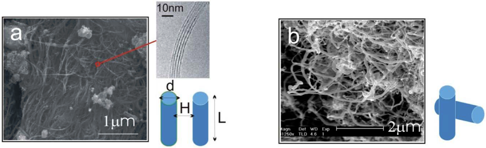
(2) ~ −10 eV per contact is obtained. This value is lower than, but comparable to what was calculated in [14], ~ −15 eV per contact, which was calculated based on the surface integral of graphene layers for a similar rolled configuration. The esults from [14] also showed a linear dependence of on the diameter d for all MWNTs. From the estimate, we can see that the energy associated with each contact is orders of magnitude greater than the room-temperature thermal energy. The number of contacts which can form between neighboring CNT pairs increase dramatically with the length of nanotubes. Therefore, the binding of a clustered network of long MWNTs is extremely strong, where each contact acts effectively as a physical cross-link fixing the network.
 ~ −100 eV [14] for a 80 nm diameter MWNT, we obtain ε ~ 16 kPa. The above two examples demonstrate the vastly different energy levels, with many orders of magnitude difference, required to separate the CNTs of various as-grown morphologies.
2.2. Energy Density Delivered from Mixing
 ), i.e.,
  . We next consider the magnitude of the energy density that can be delivered by a mechanical mixing or a sonication technique.) for the common melt shear mixing is dependent on the rotational speed of the mixer blade (ω in units of rad/s), and the geometry of the mixer and the container. For a typical Couette (concentric cylinder) shear-mixing geometry,
  , with R being the radius of the container, and h the spacing between the leading edge of the mixer blade and the inner wall of the container. The standard Couette mixing conditions in reference [15] have yielded a strain rate of 500 s−1; experimental setups of different geometries could obtain a fluid strain rate as high as 4,000 s−1[24]. Therefore, using a viscous polymer melt such as PDMS uncross-linked polymer (η = 5.6 Pa∙s), the shear stress imparted by the mixing medium is below 20 kPa. Note that if one wishes to shear-mix in a low-viscosity solvent (such as water, toluene or chlorophorm), the shear stress delivered to the CNT clusters will drop to below 50 Pa, offering very little hope of achieving dispersion. The simple message of this estimate is: shear mixing is only suitable for dispersion of MWNT clusters in high-viscosity polymer melts.
2.3. Fracture of CNTs during Mixing

 , where Ri is the characteristic bubble radius. It is expected that most nano-filaments, when located close to the imploding bubble (typical sizes of tens of micron), will re-orient themselves to align with the radial flow field. The final configuration of the filament with respect to the imploding bubble and its associated flow field is schematically illustrated in Figure 3(a). Within this framework, an affine estimate is used to calculate the stress that is exerted on a suspended filament by the viscous forces transmitted from the solvent.
 and wall velocity
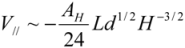
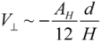
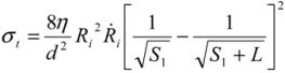
  . Near the bubble there is a segment of the filament with a length L (with S1 and S2 being the starting and the ending positions of the filament) and a diameter d, which is accelerated by the surrounding viscous (surface shear) forces. Let us take a frame moving with the instantaneous velocity of the filament and assume the tube is in a quasi-equilibrium and its center of mass moving with a speed of Vtube. Surface shear stresses are created when the local velocity of the fluid flow Vs is different from the velocity of the filament Vtube. Assuming that the tube surface is non-slip and the characteristic length scale of the velocity decay across the cylindrical filament is of the order of its diameter d, the local shear strain on the surface can be approximated as (Vs − Vtube)/d. This gives the local shear stress as
 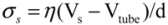 , with η the solvent viscosity.
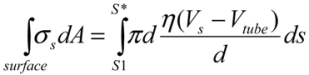 (3)
(3)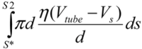 . Since the total shear forces applied on the tube surface add to zero, these two forces are balanced. After cancelation of factors on both sides, one obtains:
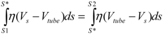 (4)
(4)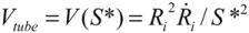 , one can solve Equation (4), giving
  .
. . The instantaneous velocity field of the fluid medium surrounding the bubble Vs is illustrated, of which magnitude is indicated by the color-coded scale bar. The filament immersed in the flow can only have a single velocity Vtube along its entire length, hence local surface shear stresses σs are created. The variation of σs w.r.t the position on the filament are shown in (b) and (c). The values of the surface stresses are normalized against the position-independent parameters, and the distance is normalized against the length of the filament.
. The instantaneous velocity field of the fluid medium surrounding the bubble Vs is illustrated, of which magnitude is indicated by the color-coded scale bar. The filament immersed in the flow can only have a single velocity Vtube along its entire length, hence local surface shear stresses σs are created. The variation of σs w.r.t the position on the filament are shown in (b) and (c). The values of the surface stresses are normalized against the position-independent parameters, and the distance is normalized against the length of the filament.
. The instantaneous velocity field of the fluid medium surrounding the bubble Vs is illustrated, of which magnitude is indicated by the color-coded scale bar. The filament immersed in the flow can only have a single velocity Vtube along its entire length, hence local surface shear stresses σs are created. The variation of σs w.r.t the position on the filament are shown in (b) and (c). The values of the surface stresses are normalized against the position-independent parameters, and the distance is normalized against the length of the filament.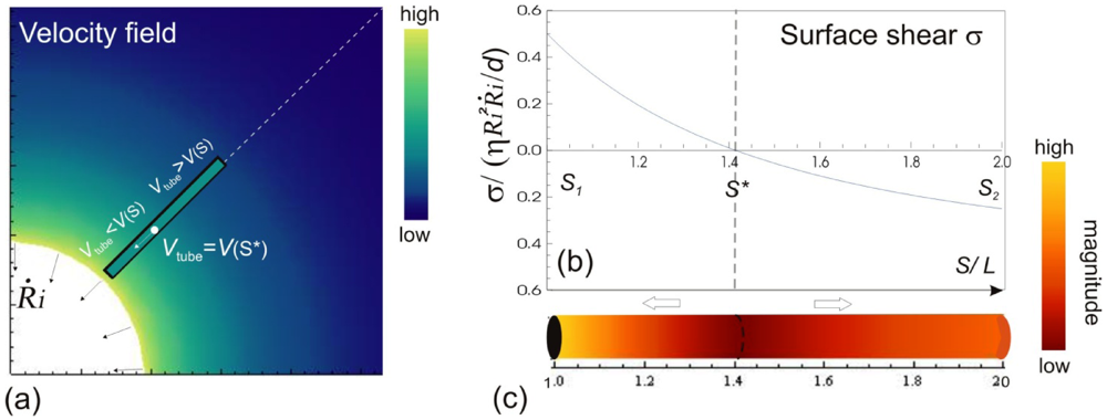
 (5) = 10 μm, and mean
  ~ 108 s−1), the CNT diameter d ~ 10 nm, the viscosity of a typical low-molecular weight solvent η ~ 0.1 Pa·s, and S1 ~L ~10 μm (the maximal stress occurs for a filament positioned closest to the bubble such that S1 = Ri), one obtains the estimate for the maximum tensile stress generated by viscous forces near the imploding bubble: σt > 100 GPa. This is enough to break most nanotubes! However, it is also clear from the Equation (5) that the tensile stress on the tube decreases dramatically as the tube length L diminishes, and a characteristic threshold length Llim exists for tube scission, for a set of pre-defined parameters η, d and . If the value of breaking stress (ultimate tensile strength) of the nanotube is σ*, then this threshold length, after small-parameter expansion of Equation (5), is:
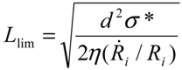 (6)
(6) and in tube breakage. We can further re-arrange Equation (6) to the form of
  , by replacing Llim with L, the starting length of a filament. We see that the left hand side contains purely the filament parameters, the aspect ratio (L/d), and the strength of the fiber σ*; while the right hand side is equal to the stress induced during cavitation, σson. Therefore, we have obtained an important filament fracture resistance parameter
  . If a filament has > σson, it will not fracture during sonication; on the other hand, when < σson, fracture occurs, and L will decrease until L = Llim as discussed above. Filaments with higher strength and lower aspect ratio are more resistant to fracture during sonication, as one would expect.
2.4. Effects of Shear-Mixing and Sonication
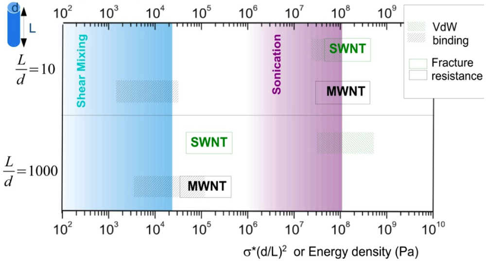
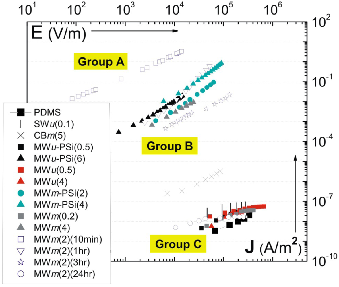
introduced previously (which has a dimension of energy density). The span of values in  is resulted from the different ranges of strengths reported for CNTs, such that σ∗MWNT ~ 3–100 GPa, and σ∗MWNT ~ 10–100 GPa [29,30,31,32,33]. To understand the diagram, we first focus on the mixing conditions. High speed shear mixing in a high viscosity polymer melt can deliver an energy density reaching 104 Pa (as derived in the previous section). However, this energy level is still orders of magnitude lower than an ultrasonic cavitation event. For an aspect ratio of 10, the fracture resistance of SWNTs is of a slightly higher value than the binding energy of their aggregates. Ultrasonication just delivers a sufficient stress level to separate the SWNT aggregates without causing much fracture to individual nanotubes. For MWNTs, one finds that high viscosity shear mixing is able to separate the aggregates apart. Shear mixing is a better dispersion method because it can effectively separate the MWNTs without causing damage to the filament. For an aspect ratio of 1,000, which is relevant to the as-produced CNT sources, one notices that the fracture resistance of both SWNTs and MWNTs are lower than the stress input level delivered by sonication. On the other hand, shear mixing is not able to achieve a stress level matching the binding energy density. A dilemma therefore arises here, such that for complete separation of long CNTs, the tubes will also be broken during the process.
3. Stability of Carbon Nanotube Dispersion
 , with a being the particle size,
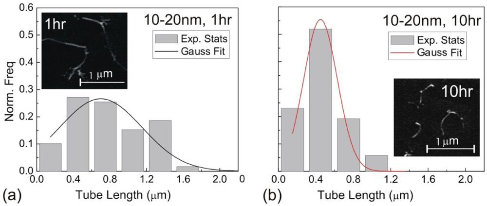
  being the density difference between the solute and the surrounding medium. It is thus apparent that re-aggregation can be promoted by sedimentation, due to the power-four dependence on the particle size. Most organic solvents and polymeric melts have densities of the order ~1 g/cm3, which are lower than various types of CNTs (1.4 to 2 g/cm3). This gives an estimate of the critical diameter of CNT cluster for sedimentation ~1 μm (cf. as-produced CNTs commonly have lengths greater than ~1 μm). Although the above formula only provides a very crude estimate without considering the shape effect of the particles, it points out the great difficulty in obtaining a homogenous solution of CNTs with long-time stability. On the other hand, sonication processing can result in apparently enhanced dispersion through ‘sonication cutting’ [20,28], such that the decreased lengths makes the nanotubes less energetically favorable to re-aggregate and sediment after the removal of sonication. Although this process can reduce the bundle sizes of SWNTs, it is unlikely to produce individually separated SWNTs. This is because the critical tens of nanometers length regime (a length required to counteract van der Waals attraction, see Section 2.3 above) is below the limiting tube length (Llim) achievable by ultrasonication [20]. Such a short length also limits the applications of SWNTs.
3.1. Kinetically Sustained Metastable State

3.2. Thermodynamically Stable Dispersion States

 |
4. Correlating the Physical Properties and the Microstructure
| Notation | Filler addition | Processing method | Mixing time |
|---|---|---|---|
| MWu (wt%) | MWNTs: 0.5 wt%, 4 wt% | ultrasonication | 8 h |
| MWu -PSi(wt%) | MWNTs: 0.5 wt% (filtered) | Psi assisted dispersion | 8 h |
| 6 wt% (filtered) | ultrasonication | ||
| MWm (wt%) | MWNTs: 0.2 wt% to 4 wt% | Shear mixing | 24 h |
| MWm -PSi(wt%) | MWNTs: 2 wt%, 4 wt% | PSi assisted dispersion, | 24 h |
| Shear mixing | |||
| MWm (2)(t) | MWNTs: 2 wt% | Shear mixing | t: 10 min; 1 h; |
| 3 h; 24 h | |||
| SWu (0.1) | SWNTs: 0.1 wt% | ultrasonication | 40 min |
| CBm (5) | Carbon Black: 5 wt% | Shear mixing | 24 h |
4. Conclusions
Acknowledgements
References
- Ajayan, P.M.; Stephan, O.; Colliex, C.; Trauth, D. Aligned carbon nanotube arrays formed by cutting a polymer resin nanotube composite. Science 1994, 265, 1212–1214. [Google Scholar]
- Lourie, O.; Cox, D.M.; Wagner, H.D. Buckling and collapse of embedded carbon nanotubes. Phys. Rev. Lett. 1998, 81, 1638–1642. [Google Scholar]
- Schadler, L.S.; Giannarisand, S.C.; Ajayan, P.M. Load transfer in carbon nanotube epoxy composites. Appl. Phys. Lett. 1998, 73, 3842–3845. [Google Scholar] [CrossRef]
- Sekitani, T.; Nakajima, H.; Maeda, H.; Fukushima, T.; Aida, T.; Hata, K.; Someya, T. Stretchable active-matrix organic light-emitting diode display using printable elastic conductors. Nature Mater. 2009, 8, 494–499. [Google Scholar]
- Yu, C.; Masarapu, C.; Rong, J.; Wei, B.; Jiang, H. Stretchable supercapacitors based on buckled single-walled carbon-nanotube macrofilms. Adv. Mater. 2009, 21, 4793–4797. [Google Scholar] [CrossRef]
- Hu, L.; Pasta, M.; Mantia, F.L.; Cui, L.; Jeong, S.; Deshazer, H.D.; Choi, J.W.; Han, S.M.; Cui, Y. Stretchable, porous, and conductive energy textiles. Nano Lett. 2010, 10, 708–714. [Google Scholar]
- Huang, Y.Y.; Terentjev, E.M. Transparent electrodes with a nanostructured coating. ACS Nano 2011, 5, 2082–2089. [Google Scholar]
- Ahir, S.V.; Terentjev, E.M. Actuation in polymer-nanotube composites. Nature Mater. 2005, 4, 491–495. [Google Scholar]
- Pelrine, R.; Kornbluh, R.; Pei, Q.; Joseph, J. High-speed electrically actuated elastomers with strain greater than 100%. Science 2000, 287, 836–839. [Google Scholar] [CrossRef]
- Bar-Cohen, Y. Electroactive Polymer (EAP) Actuators as Artificial Muscles: Reality, Potential, and Challenges, 2nd ed; SPIE Press Book: Bellingham, WA, USA, 2011. [Google Scholar]
- Girifalco, L.A.; Hodak, M.; Lee, R.S. Carbon nanotubes, buckyballs, ropes, and a universal graphitic potential. Phys. Rev. B 2000, 62, 13104–13110. [Google Scholar]
- Hamaker, H.C. The London van der Waals attraction between spherical particles. Physica 1937, 4, 1058–1072. [Google Scholar] [CrossRef]
- Israelachvili, J. Intermolecular and Surface Forces, 2nd ed; Academic Press: London, UK, 1992. [Google Scholar]
- Zhbanov, A.I.; Pogorelov, E.G.; Chang, Y.C. Van der Waals interaction between two crossed carbon nanotubes. ACS Nano 2010, 4, 5937–5945. [Google Scholar]
- Huang, Y.Y.; Ahir, S.V.; Terentjev, E.M. Rheology of carbon nanotube dispersions. Phys. Rev. B 2006, 73, 125422. [Google Scholar]
- Andrews, R.; Jacques, D.; Minot, M.; Rantell, T. Fabrication of carbon multi-wall nanotube/polymer composites by shear mixing. Macromol. Mater. Eng. 2002, 287, 395–403. [Google Scholar] [CrossRef]
- Park, J.H.; Alegaonkar, P.S.; Jeon, S.Y.; Yoo, J.B. Carbon nanotube composite: Dispersion routes and field emission parameters. Compos. Sci. Technol. 2008, 68, 753–759. [Google Scholar] [CrossRef]
- Wichmann, M.H.G.; Sumeth, J.; Fiedler, B.; Gojny, F.H.; Schulte, K. Multi-wall carbon nanotube/epoxy composites produced with a masterbatch process. Mech. Comp. Mater. 2006, 42, 395–406. [Google Scholar] [CrossRef]
- Huang, Y.Y.; Terentjev, E.M. Dispersion and rheology of carbon nanotubes in polymers. Int. J. Mater. Form. 2008, 1, 63–74. [Google Scholar] [CrossRef]
- Huang, Y.Y.; Knowles, T.P.J.; Terentjev, E.M. Strength of nanotubes, filaments, and nanowires from sonication-induced scission. Adv. Mater. 2009, 21, 3945–3948. [Google Scholar] [CrossRef]
- Yamamoto, Y.; Miyauchi, Y.; Motoyanagi, J.; Fukushima, T.; Aida, T.; Kato, M.; Maruyama, S. Improved bath sonication method for dispersion of individual single-walled carbon nanotubes using new triphenylene-based surfactant. Jpn. J. Appl. Phys. 2008, 47, 2000–2004. [Google Scholar]
- Ramasubramaniama, R.; Chen, J. Homogeneous carbon nanotube/polymer com-posites for electrical applications. Appl. Phys. Lett. 2003, 83, 2928–2930. [Google Scholar] [CrossRef]
- Strano, M.; Moore, V.C.; Miller, M.K.; Allen, M.; Haroz, E.; Kittrell, C.; Hauge, R.H.; Smalley, R.E.J. The role of surfactant adsorption during ultrasonication in the dispersion of single-walled carbon nanotubes. Nanosci. Nanotechnol. 2003, 3, 81–86. [Google Scholar] [CrossRef]
- Chen, G.X.; Li, Y.J.; Shimizu, H. Ultrahigh-shear processing for the preparation of polymer/carbon nanotube composites. Carbon 2007, 45, 2334–2340. [Google Scholar] [CrossRef]
- Nguyen, T.Q.; Liang, Q.Z.; Kausch, H.H. Kinetics of ultrasonic and transient elongational flow degradation: A comparative study. Polymer 1997, 38, 3783–3793. [Google Scholar]
- Lohse, D. Sonoluminescence-cavitation hots up. Nature 2005, 434, 33–34. [Google Scholar]
- Gedanken, A. Using sonochemistry for the fabrication of nanomaterials. Ultrason. Sonochem. 2004, 11, 47–55. [Google Scholar] [CrossRef]
- Kerr, C.J.; Huang, Y.Y.; Marshall, J.E.; Terentjev, E.M. Effect of filament aspect ratio on the dielectric response of multiwalled carbon nanotube composites. J. Appl. Phys. 2011, 109, 094109. [Google Scholar]
- Wong, E.W.; Sheehan, P.E.; Lieber, C.M. Nanobeam mechanics: Elasticity, strength, and toughness of nanorods and nanotubes. Science 1997, 277, 1971–1975. [Google Scholar] [CrossRef]
- Xie, S.S.; Li, W.Z.; Pan, Z.W.; Chang, B.H.; Sun, L.F. Mechanical and physical properties on carbon nanotube. J. Phys. Chem. Sol. 2000, 61, 1153–1158. [Google Scholar] [CrossRef]
- Ding, W.; Calabri, L.; Kohlhaas, K.M.; Chen, X.; Dikin, D.A.; Ruo, R.S. Modulus, fracture strength, and brittle vs. plastic response of the outer shell of arc-grown multi-walled carbon nanotubes. Exp. Mech. 2007, 47, 25–36. [Google Scholar] [CrossRef]
- Peng, B.; Locascio, M.; Zapol, P.; Li, S.; Mielke, S.L.; Schatz, G.C.; Es-pinosa, H.D. Measurements of near-ultimate strength for multiwalled carbon nanotubes and irradiation-induced crosslinking improvements. Nat. Nanotechnol. 2008, 3, 626–631. [Google Scholar] [CrossRef]
- Barber, A.H.; Andrews, R.; Schadler, L.S.; Wagner, H.D. On the tensile strength distribution of multiwalled carbon nanotubes. Appl. Phys. Lett. 2005, 87, 203106. [Google Scholar]
- Lin-Gibson, S.; Pathak, J.A.; Grulke, E.A.; Wang, H.; Hobbie, E.K. Elastic flow instability in polymer-dispersed nanotubes. Phys. Rev. Lett. 2004, 92, 48302. [Google Scholar]
- Chen, J.; Hamon, M.A.; Hu, H.; Chen, Y.S.; Rao, A.M.; Eklund, P.C.; Haddon, R.C. Solution properties of single-walled carbon nanotubes. Science 1998, 282, 95–98. [Google Scholar] [CrossRef]
- Hamon, M.A.; Hu, H.; Bhowmik, P.; Niyogi, S.; Zhao, B.; Itkis, M.E.; Haddon, R.C. End-group and defect analysis of soluble single-walled carbon nanotubes. Chem. Phys. Lett. 2001, 347, 8–12. [Google Scholar] [CrossRef]
- Sinnott, S. Chemical functionalization of carbon nanotubes. J. Nanosci. Nanotech. 2002, 2, 112–123. [Google Scholar]
- Ausman, K.; Piner, R.; Lourie, O.; Ruoff, R. Organic solvent dispersions of single-walled carbon nanotubes: Toward solutions of pristine nanotubes. J. Phys. Chem. B 2000, 104, 8911–8915. [Google Scholar] [CrossRef]
- Bergin, S.D.; Nicolosi, V.; Streich, P.V.; Giordani, S.; Sun, Z.; Windle, A.H.; Ryan, P.; Niraj, N.P.P.; Wang, Z.T.T.; Carpenter, L.; et al. Towards solutions of single-walled carbon nanotubes in common solvents. Adv. Mater. 2008, 20, 1876–1881. [Google Scholar]
- Giordani, S.; Bergin, S.D.; Nicolosi, V.; Lebedkin, S.; Kappes, M.M.; Blau, W.J.; Coleman, J.N. Debundling of single-walled nanotubes by dilution: Observation of large populations of individual nanotubes in amide solvent dispersions. J. Phys. Chem. B 2006, 110, 15708–15718. [Google Scholar]
- Russel, W.B.; Saville, D.A.; Schowalter, W.R. Colloidal Dispersions; Cambridge University Press: Cambridge, UK, 1992. [Google Scholar]
- Sun, Z.; Nicolosi, V.; Rickard, D.; Bergin, S.D.; Aherne, D.; Coleman, J.N. Quantitative evaluation of surfactant-stabilized single-walled carbon nanotubes: Dispersion quality and its correlation with zeta potential. J. Phys. Chem. C 2008, 112, 10692–10699. [Google Scholar]
- Bonard, J.M.; Stora, T.; Salvetat, J.P.; Maier, F.; Stockli, T.; Duschl, C.; Forro, L.; de Heer, W.A.; Chatelain, A. Purification and size-selection of carbon nanotubes. Adv. Mater. 1997, 9, 827–831. [Google Scholar] [CrossRef]
- Islam, M.F.; Rojas, E.; Bergey, E.M.; Johnson, A.T.; Yodh, A.G. High weight fraction surfactant solubilization of single-wall carbon nanotubes in water. Nano Lett. 2003, 3, 269–273. [Google Scholar] [CrossRef]
- Li, S.; Daniel Blankschtein, D. Role of the bile salt surfactant sodium cholate in enhancing the aqueous dispersion stability of single-walled carbon nanotubes: A molecular dynamics simulation study. J. Phys. Chem. B 2010, 114, 15616–15625. [Google Scholar]
- Liu, Z.; Tabakman, S.M.; Chen, Z.; Dai, H. Preparation of carbon nanotube bioconjugates for biomedical applications. Nat. Protoc. 2009, 4, 1372–1381. [Google Scholar] [CrossRef]
- Wu, Y.; Hudson, J.A.S.; Lu, Q.; Moore, J.M.; Mount, A.S.; Apparao, M.; Rao, A.M.; Alexov, E.; Ke, P.C. Coating single-walled carbon nanotubes with phospholipids. J. Phys. Chem. B 2006, 110, 2475–2478. [Google Scholar]
- Rastogia, R.; Kaushala, R.; Tripathib, S.K.; Sharmaa, A.L.; Kaura, I.; Bharadwaj, L.M. Comparative study of carbon nanotube dispersion using surfactants. J. Colloid Interface Sci. 2008, 328, 421–428. [Google Scholar] [CrossRef]
- Zheng, M.; Jagota, A.; Semke, E.; Diner, B.; Mclean, R.; Lustig, S.; Richardson, R.; Tassi, N. DNA-assisted dispersion and separation of carbon nanotubes. Nat. Mater. 2003, 2, 338–342. [Google Scholar] [CrossRef]
- Tu, X.; Manohar, S.; Jagota, A.; Zheng, M. DNA sequence motifs for structure-specific recognition and separation of carbon nanotubes. Nature 2009, 460, 250–253. [Google Scholar]
- Karajanagi, S.S.; Yang, H.; Asuri, P.; Sellitto, E.; Dordick, J.S.; Kane, R.S. Protein-assisted solubilization of single-walled carbon nanotubes. Langmuir 2006, 22, 1392–1395. [Google Scholar]
- O’Connell, M.J.; Boul, P.B.; Ericson, L.M.; Huffman, C.; Wang, Y.; Haroz, E.; Kuper, C.; Tour, J.; Ausman, K.D.; Smalley, R.E. Reversible water-solubilization of single-walled carbon nanotubes by polymer wrapping. Chem. Phys. Lett. 2001, 342, 265–271. [Google Scholar] [CrossRef]
- Hasan, T.; Scardaci, V.; Tan, P.H.; Rozhin, A.G.; Milne, W.I.; Ferrari, A.C. Stabilization and “debundling” of single-wall carbon nanotube dispersions in N-methyl-2-pyrrolidone (NMP) by polyvinylpyrrolidone (PVP). J. Phys. Chem. C 2007, 111, 12594–12602. [Google Scholar]
- Zou, J.H.; Liu, L.W.; Chen, H.; Khondaker, S.I.; McCullough, R.D.; Huo, Q.; Zhai, L. Dispersion of pristine carbon nanotubes using conjugated block copolymers. Adv. Mater. 2008, 20, 2055–2060. [Google Scholar] [CrossRef]
- Christian, E.; Rahman, G.M.A.; Jux, N.; Balbinot, D.; Guldi, D.M.; Paolucci, F.; Marcaccio, M.; Paolucci, D.; Melle-Franco, M.; Zerbetto, F.; et al. Interactions in single wall carbon nanotubes/pyrene/porphyrin nanohybrids. J. Am. Chem. Soc. 2006, 128, 11222–11231. [Google Scholar]
- Nakashima, N.; Tomonari, Y.; Murakami, H. Water-soluble single-walled carbon nanotubes via noncovalent sidewall-functionalization with a pyrene-carrying ammonium ion. Chem. Lett. 2002, 31, 638–639. [Google Scholar]
- Ji, Y.; Huang, Y.Y.; Tajbakhsh, A.R.; Terentjev, E.M. Polysiloxane surfactants for the dispersion of carbon nanotubes in non-polar organic solvents. Langmuir 2009, 25, 12325–12331. [Google Scholar]
- Chen, J.; Liu, H.; Weimer, W.A.; Halls, M.D.; Waldeck, D.H.; Walker, G.C. Noncovalent engineering of carbon nanotube surfaces by rigid, functional conjugated polymers. J. Am. Chem. Soc. 2002, 124, 9034–9035. [Google Scholar]
- Hasan, T.; Sun, Z.; Wang, F.; Bonaccorso, F.; Tan, P.H.; Rozhin, A.G.; Ferrari, A.C. Nanotube-polymer composites for ultrafast photonics. Adv. Mater. 2009, 21, 3874–3899. [Google Scholar]
- Lisunova, M.O.; Mamunya, Y.P.; Lebovka, N.I.; Melezhyk, A.V. Percolation be-haviour of ultrahigh molecular weight polyethylene/multi-walled carbon nanotubes composites. Eur. Polym. J. 2007, 43, 949–958. [Google Scholar] [CrossRef]
- Bryning, M.B.; Islam, M.F.; Kikkawa, J.M.; Yodh, A.G. Very low conductivity threshold in bulk isotropic single wall carbon nanotube epoxy composites. Adv. Mater. 2005, 17, 1186–1191. [Google Scholar] [CrossRef]
- Huang, Y.Y.; Marshall, J.E.; Gonzalez Lopez, C.; Terentjev, E.M. Variation in carbon nanotube polymer composite conductivity from the effects of processing, dispersion, aging and sample size. 2012, in press.. [Google Scholar]
- Huang, Y.Y.; Terentjev, E.M. Tailoring the electrical properties of carbon nanotubes-polymer composite. Adv. Funct. Mater. 2010, 20, 4062–4068. [Google Scholar] [CrossRef]
- Bai, J.B.; Allaoui, A. Effect of the length and aggregate size of MWNTs on the mechanical and electrical properties of the nanocomposites. Compos. A 2003, 34, 689–694. [Google Scholar]
- Rahatekar, S.S.; Shaffer, M.S.P.; Elliott, J.A. Modelling percolation in fibre and sphere mixtures: Routes to more efficient network formation. Compos. Sci. Technol. 2010, 70, 356–362. [Google Scholar] [CrossRef]
- Kyrylyuk, A.V.; Hermant, M.C.; Schilling, T.; Klumperman, B.; Koning, C.E.; van der Schoot, P. Controlling electrical percolation in multicomponent carbon. Nat. Nanotech. 2011, 6, 364–369. [Google Scholar] [CrossRef]
- Kyrylyuk, A.V.; van der Schoot, P. Continuum percolation of carbon nanotubes in polymeric and colloidal media. Proc. Natl. Acad. Sci. USA 2008, 105, 8221–8226. [Google Scholar]
- Zhang, Q.; Rastogi, S.; Chen, D.; Lippits, D.; Lemstra, P.J. Low percolation threshold in single-walled carbon nanotube/high density polyethylene composites prepared by melt processing technique. Carbon 2006, 44, 778–785. [Google Scholar] [CrossRef]
- Cui, S.; Caneta, R.; Derrea, A.; Couzib, M.; Delhaes, P. Characterization of multiwall carbon nanotubes and influence of surfactant in the nanocomposite processing. Carbon 2003, 41, 797–809. [Google Scholar] [CrossRef]
- Mitchell, C.A.; Krishnamoorti, R. Dispersion of single-walled carbon nanotubes in poly (e-caprolactone). Macromolecules 2007, 40, 1538–1545. [Google Scholar]
© 2012 by the authors; licensee MDPI, Basel, Switzerland. This article is an open-access article distributed under the terms and conditions of the Creative Commons Attribution license (http://creativecommons.org/licenses/by/3.0/).
Share and Cite
Huang, Y.Y.; Terentjev, E.M. Dispersion of Carbon Nanotubes: Mixing, Sonication, Stabilization, and Composite Properties. Polymers 2012, 4, 275-295. https://doi.org/10.3390/polym4010275
Huang YY, Terentjev EM. Dispersion of Carbon Nanotubes: Mixing, Sonication, Stabilization, and Composite Properties. Polymers. 2012; 4(1):275-295. https://doi.org/10.3390/polym4010275
Chicago/Turabian StyleHuang, Yan Yan, and Eugene M. Terentjev. 2012. "Dispersion of Carbon Nanotubes: Mixing, Sonication, Stabilization, and Composite Properties" Polymers 4, no. 1: 275-295. https://doi.org/10.3390/polym4010275
APA StyleHuang, Y. Y., & Terentjev, E. M. (2012). Dispersion of Carbon Nanotubes: Mixing, Sonication, Stabilization, and Composite Properties. Polymers, 4(1), 275-295. https://doi.org/10.3390/polym4010275