
Influences and Failure Analysis of the Interaction Between Melt and Gas on Double-Layer Gas-Assisted Extrusion Molding of Polymer Micro-Catheters

Abstract
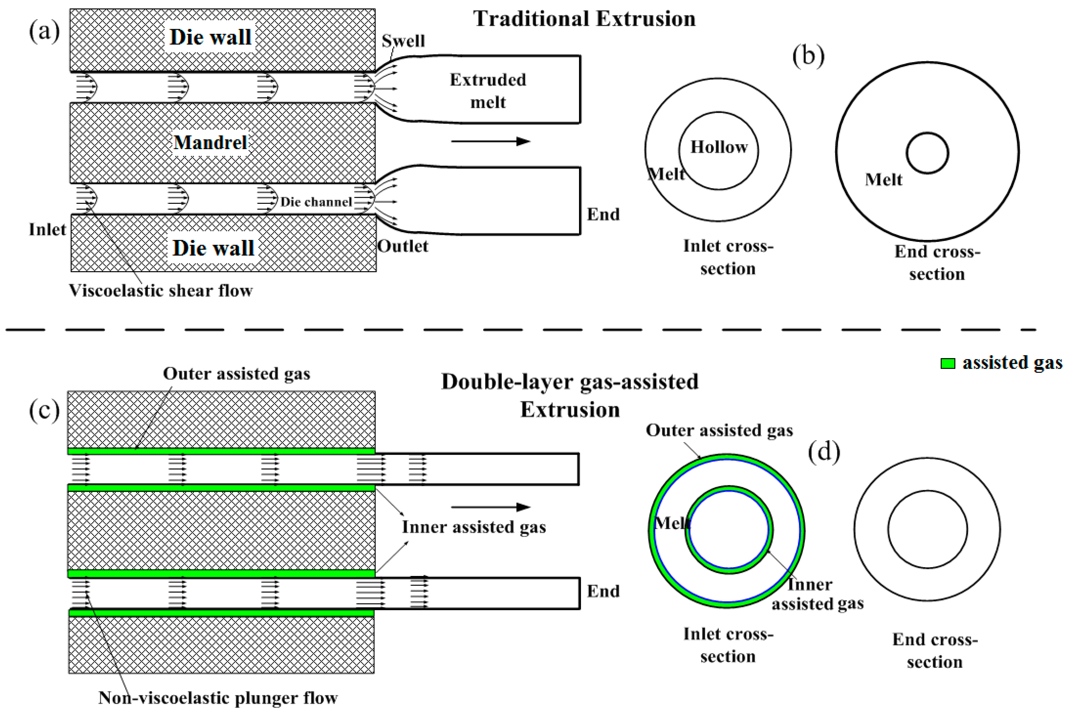
1. Introduction
2. Materials and Methods
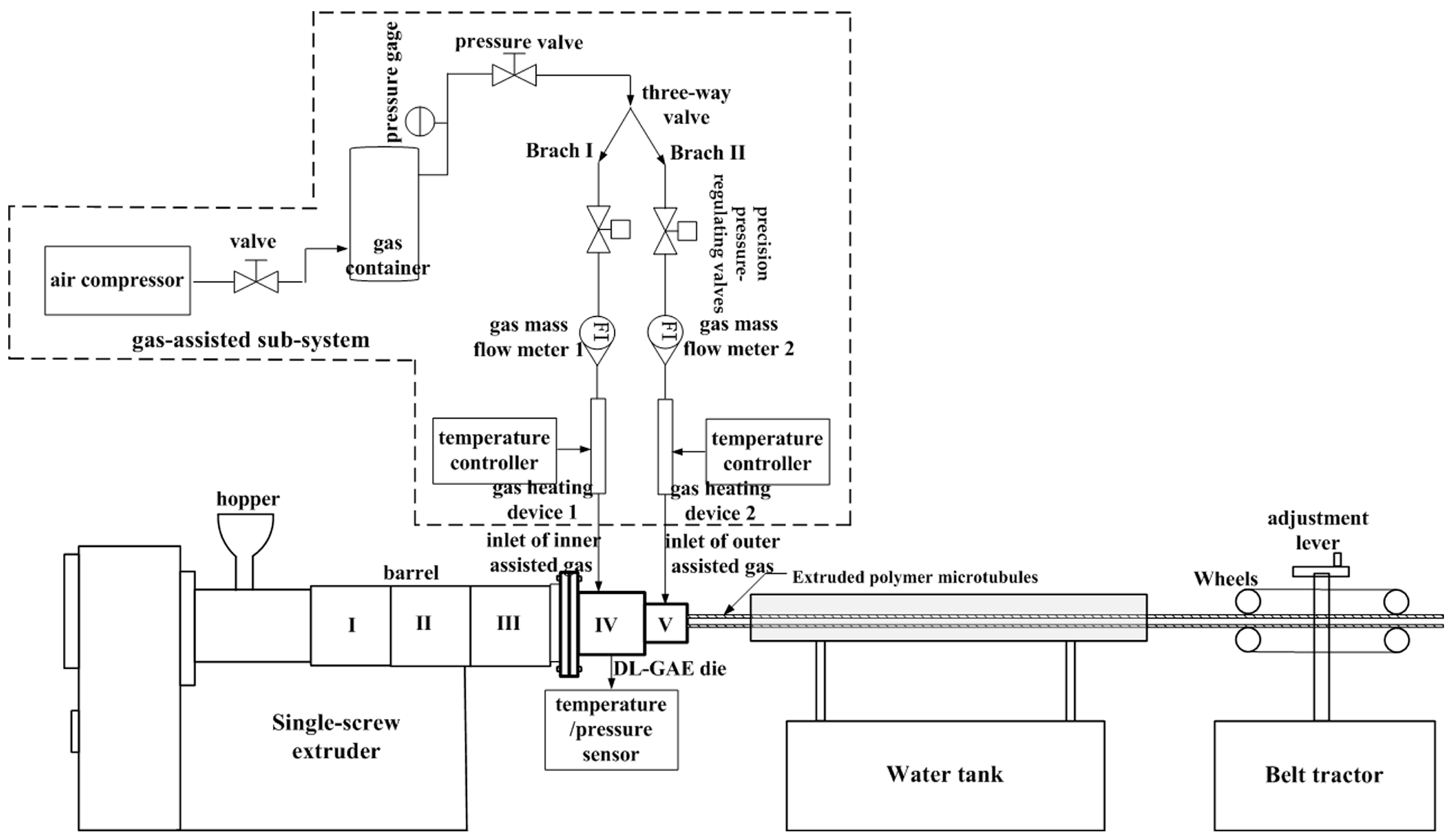
2.1. Setup
2.2. Numerical Analysis
2.2.1. Models
2.2.2. Numerical Equations
2.2.3. Boundary Conditions
- (1)
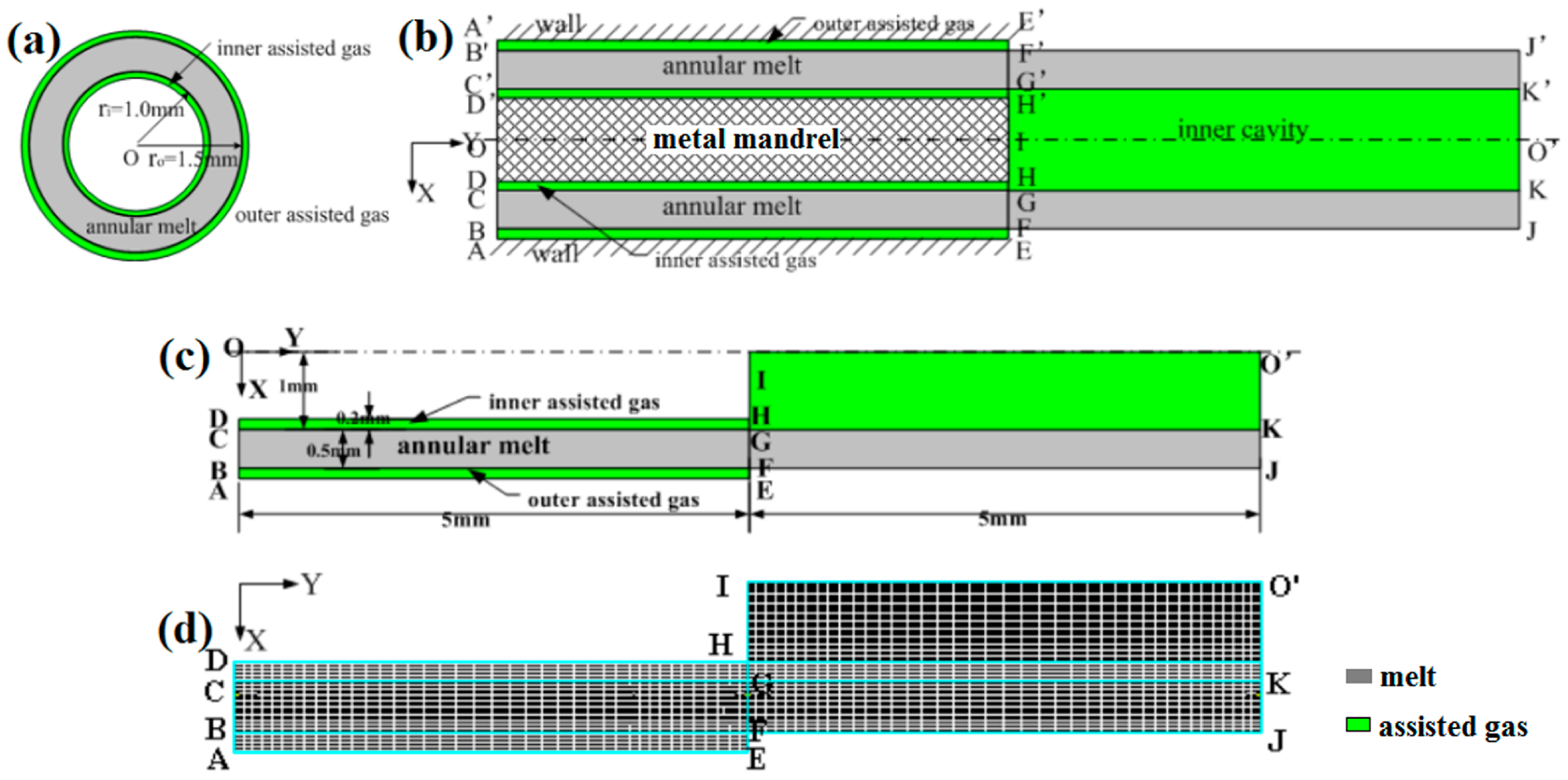
- Inlets: BC, AB, and CD are the inlets of the melt, inner assisted gas, and outer assisted gas, respectively. The fully developed flow was considered for the melt and double assisted gas flow in the shaping section of the die; these inlets obey kinetic equations, i.e., vx = 0 and ∂vy/∂y = 0 where vx and vy are the radial and axial velocities, respectively. The constant temperatures were set on all inlets.
- (2)
- Walls: AE, DH, and HI are the walls of the die and mandrel, respectively. The no-slip condition was set on the walls. In addition, the temperature of 473 K was set on all walls.
- (3)
- Free boundary: FJ is the free boundary of the extruded micro-catheters’ outside die. There are no forces on the free boundary. In addition, the heat flux boundary condition between the extruded micro-catheter and the air environment was considered. The heat flux equation [43], i.e., dQI = αI1 (TI − Tα1), was employed here, where TI and Tα1 are the temperatures of the melt and air environment, respectively, and Tα1 = 300 K. αI1 = 5 is the heat transfer coefficient.
- (4)
- Interfaces: BF and CK are the interfaces between the melt and the double assisted gas. If one assumes that there is no relative slippage on the interfaces, the dynamic and kinetic equations are obeyed, i.e., fIn = fIIn, fIs = fIIs, vIs = vIIs, and where fn and fs are the normal and tangential forces, respectively. is the normal unit vector. On the interfaces, the heat flux is also considered, i.e., dQI = dQII = αI2 (TI − Tα2). Here, αI2 is set to 10 due to strong heat exchange. Tα2 is set to 473 K.
- (5)
- Symmetry axis: IO’ is the symmetry axis.
- (6)
- Ends: KJ, EF, and KO’ are the ends of the melt, outer assisted gas, and inner assisted gas, respectively. If the traction force of the melt is considered in the simulation, a certain normal force or velocity can be imposed on the end of the melt. The outflow thermal boundary condition was imposed on the ends of the melt and gas because the temperatures could not be known in advance.
2.2.4. Material Parameters
3. Results and Discussion
3.1. Influence of Melt Flow Rate
3.2. Influence of Gas Pressure
3.2.1. Synchronized Influence of Double Assisted Gas Pressures
3.2.2. Individual Influence of Outer Assisted Gas Pressure
3.2.3. Individual Influence of Inner Assisted Gas Pressure
4. Conclusions
- (1)
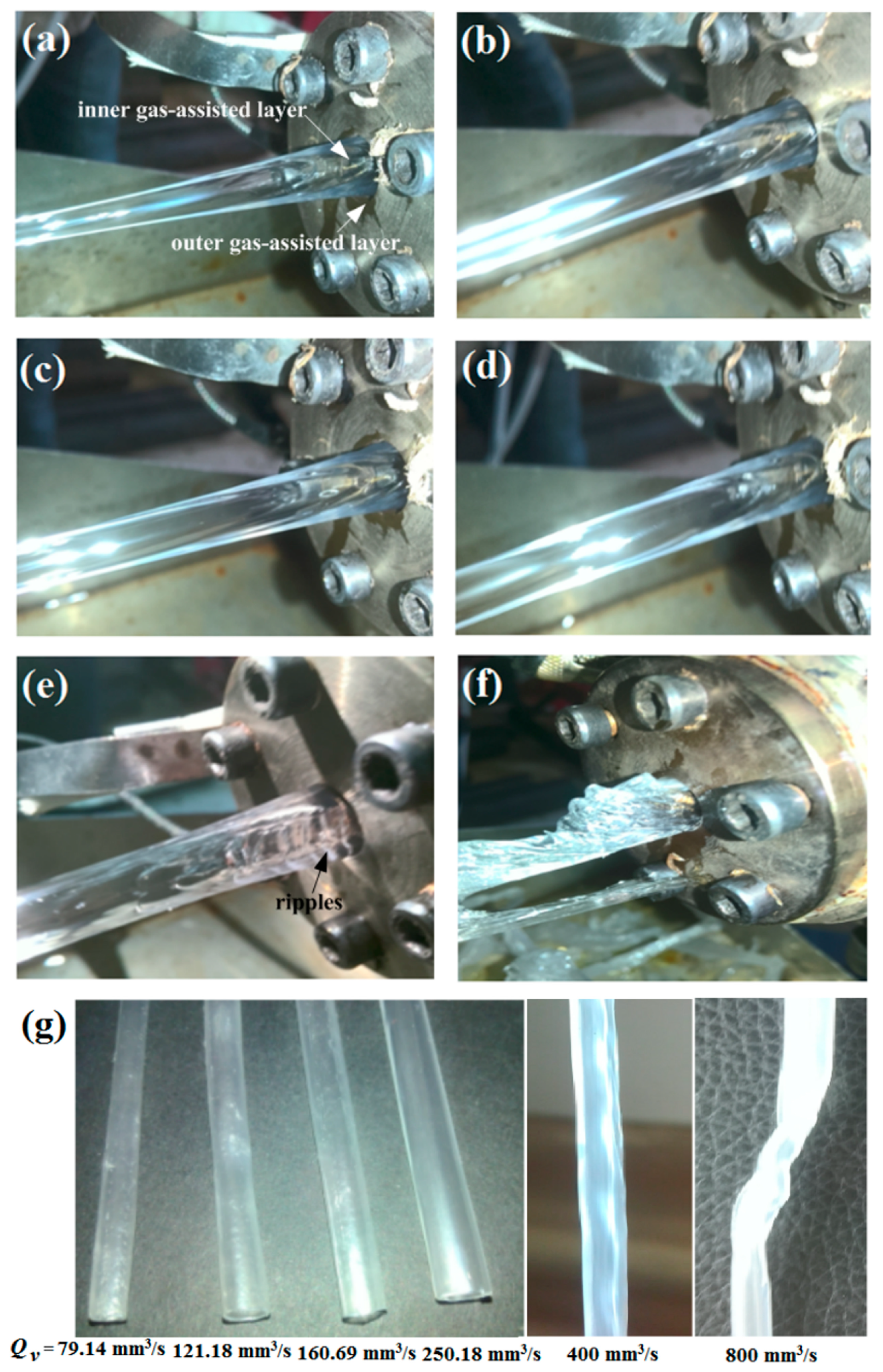
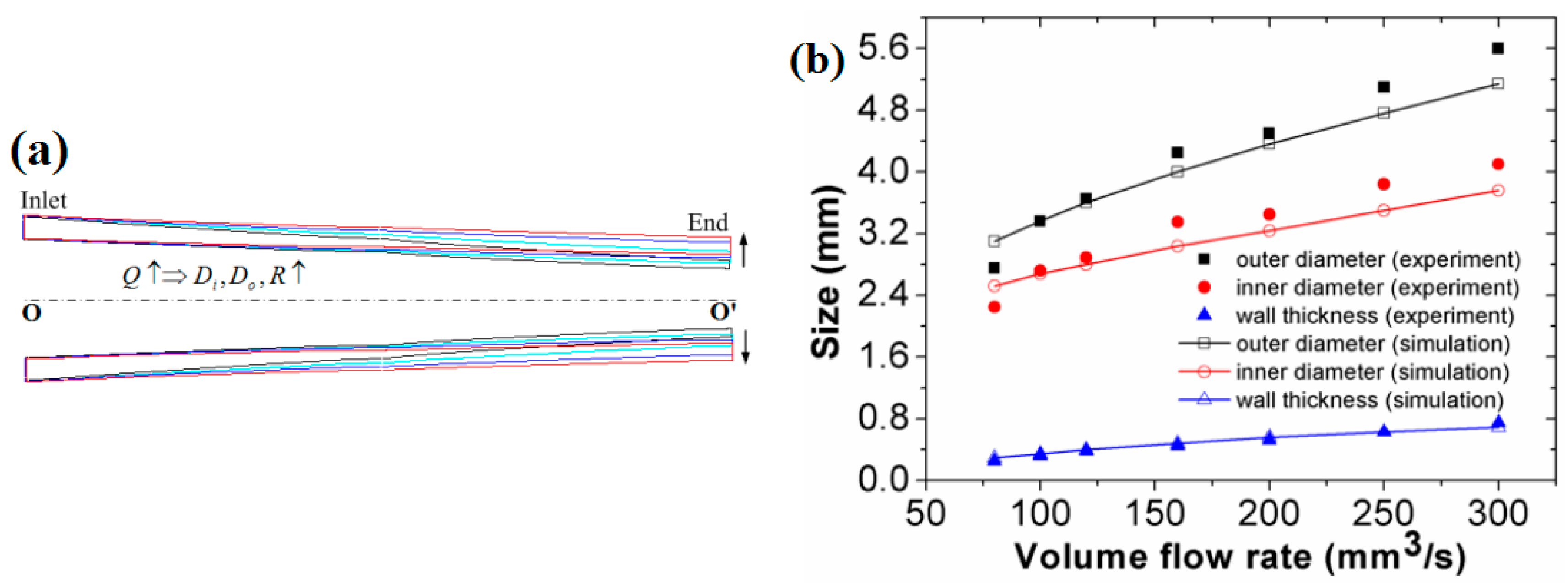
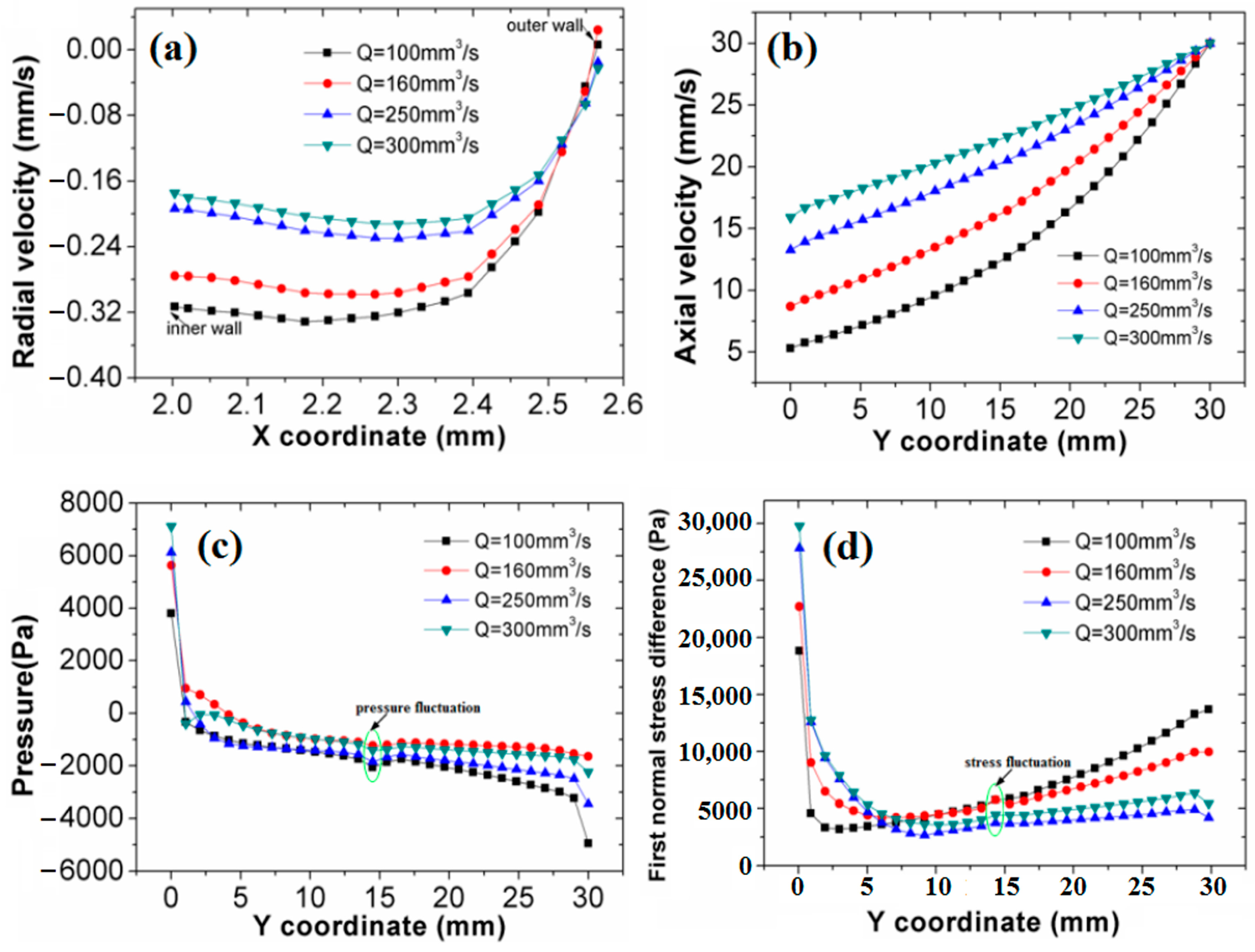
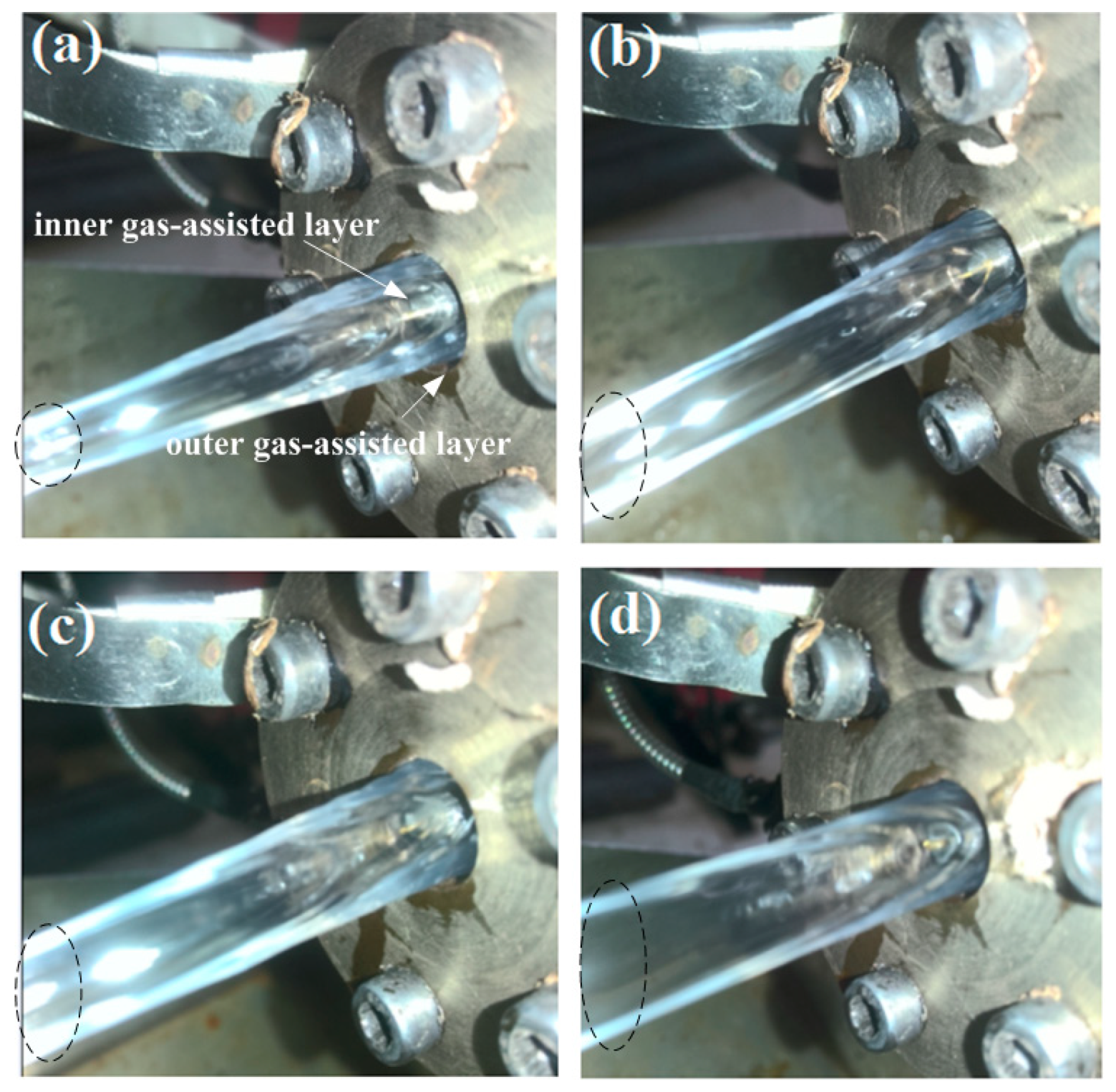
- As the melt flow rate increases, the diameter and wall thickness of the polymer micro-catheters increase. However, the stability of the double assisted gas is impacted by the higher melt flow rate. When the melt flow rate increases to a certain high value, DL-GAE failure occurs. The DL-GAE of polymer micro-catheters fails because the higher melt flow rate produces a greater shear stress and N1 in the double assisted gas, causing the flow velocity and N1 for the double assisted gas to fluctuate; this destroys the stability of the double assisted gas.
- (2)
- Regarding the influence of the double assisted gas, under a fixed melt flow rate, the pressure of the double assisted gas impacts the extrusion molding of polymer micro-catheters. With a synchronized increase in double assisted gas pressures, the diameters of the polymer micro-catheters increase, but their walls become progressively thinner. This occurs because the structure between the melt and double assisted gas is sandwich-like. The N1 of the double assisted gas exerted on the molten polymer increases with a synchronized increase in double assisted gas pressures. The diameters of the polymer micro-catheters increase, and their walls become thinner under the compression of double assisted gas with increased pressure.
- (3)
- With an individual increase in the outer assisted gas pressure, surface bumps and corrugation defects are generated. The generation of surface bumps and corrugation defects on the outer surface of polymer micro-catheters may be induced by the greater N1 of outer assisted gas injected onto the outer surface of molten polymer. With an individual increase in the inner assisted gas pressure, the diameters of polymer micro-catheters increase rapidly until the inner cavity bursts. This occurs because the first normal stress of the inner assisted gas is injected onto the surface of the inner cavity of the polymer micro-catheters, and the inner assisted gas that cannot be discharged outside in time generates accumulating pressure. The polymer melt cannot withstand the high gas pressure in the inner cavity, causing the inner cavity to gradually expand until it finally bursts.
- (4)
- To achieve DL-GAE molding of polymer micro-catheters in practice, the process parameters of the melt and double assisted gas should be controlled and maintained within a reasonable range. It is suggested that the parameters of the melt should match those of the double assisted gas. The pressures of the double assisted gas should not be excessive or deficient but should be reasonable and match the melt flow rate. When the flow rate of the melt increases, the pressures of the double assisted gas should also be increased.
Supplementary Materials
Author Contributions
Funding
Institutional Review Board Statement
Data Availability Statement
Conflicts of Interest
Abbreviations
| DL-GAE | Double-layer gas-assisted extrusion |
| PTT | Phan–Thien–Tanner |
| PP | Polypropylene |
| GAE | Gas-assisted extrusion |
References
- Cho, S.; Lee, E.; Jo, S.; Kim, G.M.; Kim, W. Extrusion characteristics of thin walled tubes for catheters using thermoplastic elastomer. Polymers 2020, 12, 1628. [Google Scholar] [CrossRef] [PubMed]
- Hao, X.; Zhang, G.; Deng, T. Improved Optimization of a Coextrusion Die with a Complex Geometry Using the Coupling Inverse Design Method. Polymers 2023, 15, 3310. [Google Scholar] [CrossRef] [PubMed]
- He, Y.; Liu, H.; Wang, Y.; Hu, W. Coating extrusion characteristics of thin-walled tubes for catheters using thermoplastic elastomer. Polymers 2025, 17, 102. [Google Scholar] [CrossRef] [PubMed]
- Bovas, B.C.; Karunamoorthy, L.; Chuan, F.B. Effect of extrusion process melt temperature on polyurethane catheter surfaces. Mater. Manuf. Process. 2018, 33, 180–185. [Google Scholar] [CrossRef]
- Zhang, X.; Huang, X.; Chen, S. Three-dimensional numerical simulations and experimental studies on the viscoelastic rheological and deformation behavior of polymer catheter in gas-assisted extrusion processing. Phys. Fluids 2024, 36, 093111. [Google Scholar] [CrossRef]
- Gloger, D.; Mileva, D.; Albrecht, A.; Hubner, G.; Androsch, R.; Gahleitner, M. Long-chain branched polypropylene: Effects of chain architecture, melt structure, shear modification, and solution treatment on melt relaxation dynamics. Macromolecules 2022, 55, 2588–2608. [Google Scholar] [CrossRef]
- Han, C.D. Influence of the die entry angle on the entrance pressure drop, recoverable elastic energy, and onset of flow instability in polymer melt flow. J. Appl. Polym. Sci. 1973, 17, 1403–1413. [Google Scholar] [CrossRef]
- Musil, J.; Zatloukal, M. Historical review of secondary entry flows in polymer melt extrusion. Polym. Rev. 2019, 59, 338–390. [Google Scholar] [CrossRef]
- Lee, W.S.; Ho, H.Y. Experimental study on extrudate swell and die geometry of profile extrusion. Polym. Eng. Sci. 2000, 40, 1085–1094. [Google Scholar] [CrossRef]
- Tian, H.; Zhao, D.; Wang, M.; Jin, Y. Effect of die lip geometry on polymer extrudate deformation in complex small profile extrusion. J. Manuf. Sci. Eng.-Trans. ASME 2017, 139, 061005. [Google Scholar] [CrossRef]
- Sentmanat, M.; Hatzikiriakos, S.G. Mechanism of gross melt fracture elimination in the extrusion of polyethylenes in the presence of boron nitride. Rheol. Acta 2004, 43, 624–633. [Google Scholar] [CrossRef]
- Ditzinger, F.; Scherer, U.; Schönenberger, M.; Holm, R.; Kuentz, M. Modified polymer matrix in pharmaceutical hot melt extrusion by molecular interactions with a carboxylic coformer. Mol. Pharm. 2018, 16, 141–150. [Google Scholar] [CrossRef]
- Dubrocq-Baritaud, C.; Darque-Ceretti, E.; Vergnes, B. Influence of die surface on the efficiency of fluoropolymer processing aids during the extrusion of linear-low density polyethylene. J. Non-Newton. Fluid 2011, 166, 847–858. [Google Scholar] [CrossRef]
- Jiang, S.; Chen, P.; Zhan, Y.; Zhao, C. Theoretical and computational analysis on the melt flow behavior of polylactic acid in material extrusion additive manufacturing under vibration field. Appl. Sci. 2020, 10, 3801. [Google Scholar] [CrossRef]
- Brzoskowski, R.; White, J.L.; Szydlowski, W.; Weissert, F.C.; Nakajima, N.; Min, K. Air-lubricated die for extrusion of rubber compounds. Rubber Chem. Technol. 1987, 60, 945–956. [Google Scholar] [CrossRef]
- Liang, R.F.; Mackley, M.R. The gas-assisted extrusion of molten polyethylene. J. Rheol. 2001, 45, 211–226. [Google Scholar] [CrossRef]
- Huang, X.; Liu, H.; Zhou, G.; Luo, Z.; Li, S. Experiment and simulation for extrustion swell in gas-assisted extrusion. Plastics 2005, 34, 55–59. (In Chinese) [Google Scholar]
- Huang, X.; Liu, H.; Zhou, G.; Luo, Z.; Li, S. Study of die swell of gas-assisted extrusion of polymer. China Plast. Ind. 2005, 33, 32–35. (In Chinese) [Google Scholar]
- Xiao, J.; Liu, H.; Huang, X.; Xu, L. Research actuality of gas-assisted extrusion technology and die design. Plastics 2008, 37, 44–47. (In Chinese) [Google Scholar]
- Xiao, J.; Liu, H.; Huang, X.; Xiong, A. Influence of slip length of gas-assisted extrusion die on pressure drop and first normal stress. Polym. Mater. Sci. Eng. 2009, 25, 167–170. (In Chinese) [Google Scholar]
- Song, J.; Huang, X. Influence of the slip length of T-shape gas-assisted extrusion on the die swell and the warping of extrudate. Polym. Mater. Sci. Eng. 2014, 30, 139–143. (In Chinese) [Google Scholar]
- Liu, H.; Lu, C.; Huang, X. Experiment of gas assisted extrusion of the plastic profile with an irregular cross-section. Polym. Mater. Sci. Eng. 2010, 26, 93–96. (In Chinese) [Google Scholar]
- Jiang, S.; Liu, H.; Huang, X.; Yu, Z.; Wang, R.; Shangguan, Y. Improved die assembly for gas-assisted sheet extrusion using different up and down gas layer thicknesses. Polym. Eng. Sci. 2021, 61, 1546–1558. [Google Scholar] [CrossRef]
- Huang, Y.; Liu, H.; Huang, X.; Xu, L. Numerical simulation of the die swell in gas-assisted coextrusion. Polym. Mater. Sci. Eng. 2010, 26, 171–174. (In Chinese) [Google Scholar]
- Deng, X.; Xiao, B.; Ren, Z.; Zhu, Z.; Liu, B. Effects of gas-assisted technology on polymer micro coextrusion. J. Polym. Eng. 2022, 42, 986–994. [Google Scholar] [CrossRef]
- Deng, X.; Liu, H. Three-dimensional viscoelastic numerical analysis of the effects of gas flow on L-profiled polymers in gas-assisted coextrusion. J. Polym. Eng. 2018, 38, 503–512. [Google Scholar] [CrossRef]
- Ren, Z.; Huang, X.; Liu, H.; Deng, X.; He, J. Numerical and experimental studies for gas assisted extrusion forming of molten polypropylene. J. Appl. Polym. Sci. 2015, 132, 42682. [Google Scholar] [CrossRef]
- Ren, Y.; Xie, P. Design of square tube gas-assisted extrusion die for polymer. Shanghai Chem. Ind. 2015, 40, 6–11. (In Chinese) [Google Scholar]
- Xu, Y.; Huang, X.; Liu, H. Numerical simulation of die swell in gas-assisted pipe extrusion. Eng. Plast. Appl. 2015, 43, 60–64. (In Chinese) [Google Scholar]
- Yu, Z.; Liu, H.; Huang, Y.; Xiong, A.; Dong, T.; Zhang, K.; Li, T. Numerical analysis on gas assisted extrusion molding of pipe profile. Plastics 2015, 44, 71–112. (In Chinese) [Google Scholar]
- Yu, Z.; Huang, Y.; Zhang, K.; Dong, T.; Li, T. Effect of air flow on pipe during the gas-assisted extrusion. Polym. Mater. Sci. Eng. 2016, 32, 113–123. (In Chinese) [Google Scholar]
- Huang, C.; Liu, H.; Huang, X.; Wan, Q.; Ren, Z. Numerical simulation of gas-assisted extrusion process of microtube. China Plast. Ind. 2015, 43, 44–47. (In Chinese) [Google Scholar]
- Ren, Z.; Huang, X.; Xiong, Z. Experimental and numerical studies for the gas-assisted extrusion forming of polypropylene micro-tube. Int. J. Mater. Form. 2020, 13, 235–256. [Google Scholar] [CrossRef]
- Luo, C.; Huang, X.; Liu, T.; Liu, H. Research on inner gas inflation improvements in double-layer gas-assisted extrusion of micro-tubes. Polymers 2020, 12, 899. [Google Scholar] [CrossRef] [PubMed]
- Liu, B.; Huang, X.; Zhang, X.; Ren, S.; Lan, Q.; Luo, C. Numerical and experimental studies on the improvement of gas chamber structure during gas-assisted extrusion. Polymers 2022, 14, 5272. [Google Scholar] [CrossRef]
- Chen, S.; Huang, X.; Liu, B.; Zhang, X. Influence of gas inlet slit width on gas-assisted plastic micro-tube extrusion. Processes 2023, 11, 2025. [Google Scholar] [CrossRef]
- Zhang, X.; Huang, X.; Liu, B.; Chen, S. Study on the melt rheological characterization of micro-tube gas-assisted extrusion based on the cross-scale viscoelastic model. Polymers 2024, 16, 973. [Google Scholar] [CrossRef] [PubMed]
- Ren, Z.; Huang, X.Y. 3D numerical simulation of the hollow square-typed polymer based on gas-assisted extrusion method. Mater. Sci. Forum 2016, 861, 189–194. [Google Scholar] [CrossRef]
- Liu, T.; Huang, X.; Luo, C.; Wang, D. The formation mechanism of the double gas layer in gas-assisted extrusion and its influence on plastic micro-tube formation. Polymers 2020, 12, 355. [Google Scholar] [CrossRef] [PubMed]
- Liu, B.; Huang, X.; Ren, S.; Luo, C. Effect of pressure difference between inner and outer gas layer on micro-tube deformation during gas-assisted extrusion. Polymers 2022, 14, 3559. [Google Scholar] [CrossRef] [PubMed]
- Ren, Z.; Huang, X.Y. Numerical comparisons on the effects of wall thickness on extrudate swell of traditional extrusion and gas-assisted extrusion for plastic microtubules. Mater. Sci. Forum 2019, 956, 253–259. [Google Scholar] [CrossRef]
- Vyazovkin, S. Activation energies and temperature dependencies of the rates of crystallization and melting of polymers. Polymers 2020, 12, 1070. [Google Scholar] [CrossRef]
- Wei, X.; Wang, Z.; Tian, Z.; Luo, T. Thermal transport in polymers: A review. J. Heat Transf. 2021, 143, 072101. [Google Scholar] [CrossRef]


| Sections | Extruder Barrel | DL-GAE Die | |||
|---|---|---|---|---|---|
| Section I | Section II | Section III | Section IV | Section V | |
| T (°C) | 200 | 210 | 215 | 220 | 220 |
| Parameter | Molten PP | Gas |
|---|---|---|
| Total viscosity ηk (Pa·s) | 2700 | 2.6 × 10⁻⁵ |
| Relaxation time λ (s) | 0.2 | 0 |
| ε | 0.23 | 0 |
| ξ | 0.18 | 0 |
| Viscosity ratio ηr | 0.12 | 0 |
| Density ρ (kg/m3) | 920 | 0.723 |
| Specific heat capacity Cpk (J/kg·K) | 1883 | 1026 |
| Thermal conductivity kk (W/m·K) | 0.22 | 0.037 |
| Viscous flow activation energy Eγ (KJ/mol) | 16,628 | 0 |
Disclaimer/Publisher’s Note: The statements, opinions and data contained in all publications are solely those of the individual author(s) and contributor(s) and not of MDPI and/or the editor(s). MDPI and/or the editor(s) disclaim responsibility for any injury to people or property resulting from any ideas, methods, instructions or products referred to in the content. |
© 2025 by the authors. Licensee MDPI, Basel, Switzerland. This article is an open access article distributed under the terms and conditions of the Creative Commons Attribution (CC BY) license (https://creativecommons.org/licenses/by/4.0/).
Share and Cite
Ren, Z.; Deng, X.; Ji, H. Influences and Failure Analysis of the Interaction Between Melt and Gas on Double-Layer Gas-Assisted Extrusion Molding of Polymer Micro-Catheters. Polymers 2025, 17, 504. https://doi.org/10.3390/polym17040504
Ren Z, Deng X, Ji H. Influences and Failure Analysis of the Interaction Between Melt and Gas on Double-Layer Gas-Assisted Extrusion Molding of Polymer Micro-Catheters. Polymers. 2025; 17(4):504. https://doi.org/10.3390/polym17040504
Chicago/Turabian StyleRen, Zhong, Xiaozhen Deng, and Haibo Ji. 2025. "Influences and Failure Analysis of the Interaction Between Melt and Gas on Double-Layer Gas-Assisted Extrusion Molding of Polymer Micro-Catheters" Polymers 17, no. 4: 504. https://doi.org/10.3390/polym17040504
APA StyleRen, Z., Deng, X., & Ji, H. (2025). Influences and Failure Analysis of the Interaction Between Melt and Gas on Double-Layer Gas-Assisted Extrusion Molding of Polymer Micro-Catheters. Polymers, 17(4), 504. https://doi.org/10.3390/polym17040504