This experimental study builds on the research program [
3] focused on additive drone manufacturing, utilizing a simple desktop printer and commercially available polymeric materials. The study [
3], representing the initial stage of this research program, identified PLA as a viable material for drone construction due to its relatively high mechanical resistance, ease of fabrication, and non-toxicity. In particular, the mechanical PLA strength was substantially (by nearly 30 times) greater than the design stress values. The deformability of FFF plastics, including creep and temperature-induced deformation, may lead to structural issues that warrant further investigation beyond the scope of this study.
The functionality of a drone’s conductive system determines the efficiency criteria of CP. The drone geometry determines the maximum cross-sectional area in this study. Thus, CP conductivity becomes the focus of this investigation, and theoretical calculations are employed to estimate the minimum conductivity required for the AM drone with an integrated conductive system to be functional.
2.1. Overview of Commercially Available CP
Several commercially available CP filaments are suitable for 3D printing.
Table 2 compares their characteristics, highlighting properties such as material composition, conductivity, 3D printing method, and application [
31,
32,
33,
34,
35,
36]. Like
Table 1, this table also organizes filaments by the conductivity specified by the manufacturer. This arrangement visualizes the impact of the filler on both conductivity and the cost of raw materials. In particular, the price of nearly 100 EUR/kg for the CB-based filaments [
31,
32,
33] makes them a promising alternative to highly conductive yet expensive copper particle-based polymers [
36] for this prototyping study. Graphene-based materials [
34,
35] are also costly but do not offer a significant increase in conductivity to justify the financial expense compared to CB-based alternatives.
This study employed a conductive PLA filament [
31] containing CB filler. The CP matrix material is the same as that selected for FFF of the drone frame in this study, which mitigates the polymers’ compatibility issues typical of multi-material polymeric composites [
37]. The CB additive consists of quasi-spherical carbon particles with a high surface area, enabling efficient electron tunneling and charge transport when uniformly dispersed throughout the polymeric matrix [
20]. It can achieve percolation at concentrations as low as 1.5–3 wt% [
21]. These CPs achieved bulk resistivities of less than 0.01 Ω·m and are compatible with thermoplastics and FFF technology, making them suitable for printed conductive circuits and low-power electronic elements [
19]. The material choice was based on a systematic review of commercially available conductive polymer filaments, ensuring the achievable conductivity within the practical constraints of procurement and regional availability. In particular, a more conductive alternative [
33] in
Table 2 was not available to purchase during the test preparation. Still, the choice of CP does not affect the research steps and methodology in this investigation, and the conclusions can be extended to apply to the alternative CPs listed in
Table 1 and
Table 2.
2.2. Conductive Specimens
The test results [
20,
38,
39] are analyzed to determine the design of the CP circuit samples. Kwok et al. [
20] used both MakerBot Dual (MakerBot, New York, NY, USA) and FlashForge Creator (Flashforge, Zhejiang, China), and Zhang et al. [
38] employed the MakerBot Replicator 2 printer (MakerBot, New York, NY, USA). On the contrary, Flowers et al. [
39] opted to build a custom 3D printer based on the design of the open-source D-Bot printer [
40] due to the limitations of suitable commercially available apparatuses for dual-material printing.
Table 3 describes the essential settings of these studies.
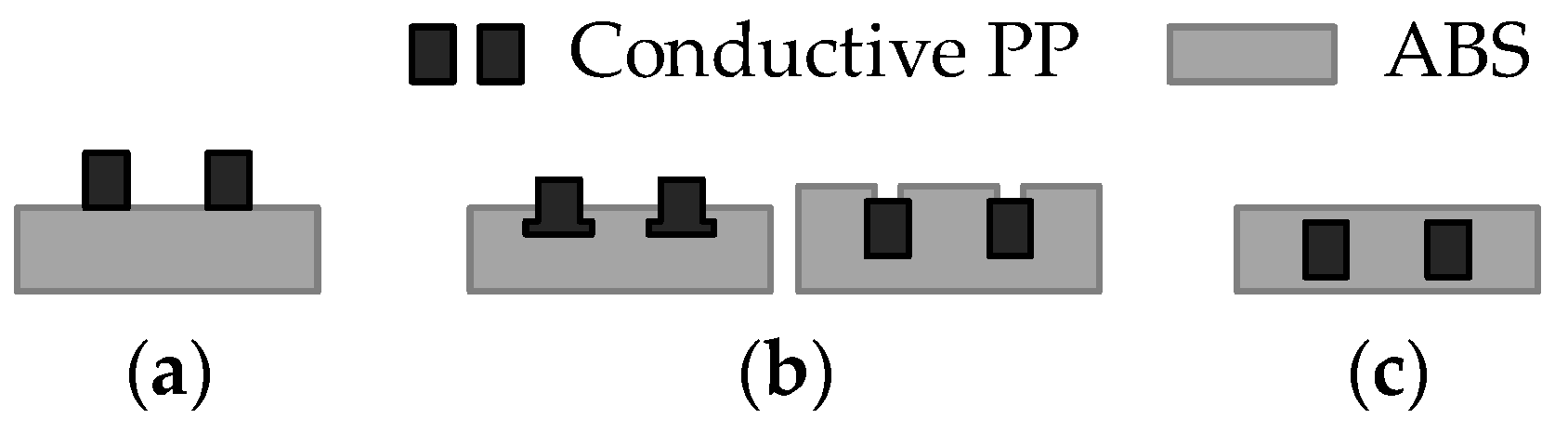
Kwok et al. [
20] explored the conductive pathway delamination problem, considering the sample geometries shown in
Figure 1. The analysis revealed that without encapsulation (
Figure 1a), delamination occurs readily through peeling, while both partial encapsulation (
Figure 1b) and complete encapsulation (
Figure 1c) prevent delamination. In the present study, the adhesion between ordinary and conductive polymers is ensured due to the compatibility of the matrix materials (
Section 2.1). Therefore, the “open” configuration (
Figure 1a) is used for the conductivity measurements to monitor electrical characteristics throughout the conductor’s depth. The drone prototypes utilize both non-encapsulated and partially encapsulated conductive pathways (
Figure 1a,b) to facilitate visual inspection of the fabrication quality. The entirely encapsulated pathways (
Figure 1c) are anticipated for the functional FFF drones.
Figure 2 shows the specimens used for the conductivity measurements in this study. The conductive samples have a fixed length of 70 mm and a width of 2 mm, while the cross-section height was systematically increased to evaluate its impact on electrical conductivity. The pathways have the following heights: 0.5 mm, 1.5 mm, 3 mm, 5 mm, 7 mm, and 10 mm. The models were processed for printing using the Bambu Studio software (Bambu Lab, Version 1.10.1.50, Shenzhen, China). Each model was configured for dual-material fabrication, employing a 1.75 mm non-conductive PLA filament (blue) as the structural base and ProtoPasta Electrically Conductive Composite PLA [
31] (black) for the conductive tracks. To ensure structural integrity and reliable electrical performance, the slicing parameters included 100% infill density and two outer wall loops, providing smooth surface finishes and precise dimensional accuracy. Print speeds were set to 200 mm/s for outer walls and 230 mm/s for infill, balancing print quality and fabrication efficiency. All specimens were printed using the P1S printer (Bambu Lab, Shenzhen, China), with a 0.4 mm nozzle and a textured build plate. The printer’s AMS facilitated seamless, automated transitions between structural and conductive materials, eliminating the need for manual intervention during fabrication. The extrusion temperature was consistently maintained at 220 °C, while the print bed was heated to 55 °C to minimize warping and ensure optimal adhesion.
The conductive specimens were fabricated with two distinct layer thicknesses—0.20 mm (
Figure 2a,b) and 0.08 mm (
Figure 2c)—to evaluate the influence of print resolution on the overall quality and functionality of the specimens. It is assumed that both geometrical parameters remain uniform throughout the length of the sample. For a sample width
b = 2.0 mm and a height
h varying between 0.5 mm and 10 mm, the resulting cross-sectional area yields a current density of approximately 10 A/m
2 to 40 A/m
2 when a direct current is applied over the variable sample length in this study. Under these conditions, the associated electric power dissipation in the 70 mm long samples remains below 100 µW, implying a negligible self-heating effect and, consequently, an insignificant variation in the material’s resistivity due to the applied bias current.
This study also examines several designs of the contacts between the prototype specimens and the power supply and receiver: mechanical (bolted), wrapped, and direct contact without additional wires. The first two contacts were used for the conductive prototypes (
Figure 3), whereas the last one was applied in the drone prototype.
The bolted contact provides a straightforward reference, while the wrapped alternative reflects the fabrication method of mechanically and electrically stable connections outlined in the MIL-STD-1130C standard [
41], which specifies requirements for solderless wrapped electrical connections. The National Aeronautics and Space Administration (NASA) also endorses wire-wrapping for specific applications [
42]. According to NASA standards, this technique ensures a gas-tight joint, as each 90° turn around the square post fractures the wire’s oxide layer, promoting a stable connection (
Figure 3b). This method provides a stable, electrically efficient connection that resists vibration and mechanical stress, minimizing resistance fluctuations and ensuring long-term durability. Using wrapping techniques around posts helps improve contact reliability, essential for maintaining stable electrical performance in drone applications.
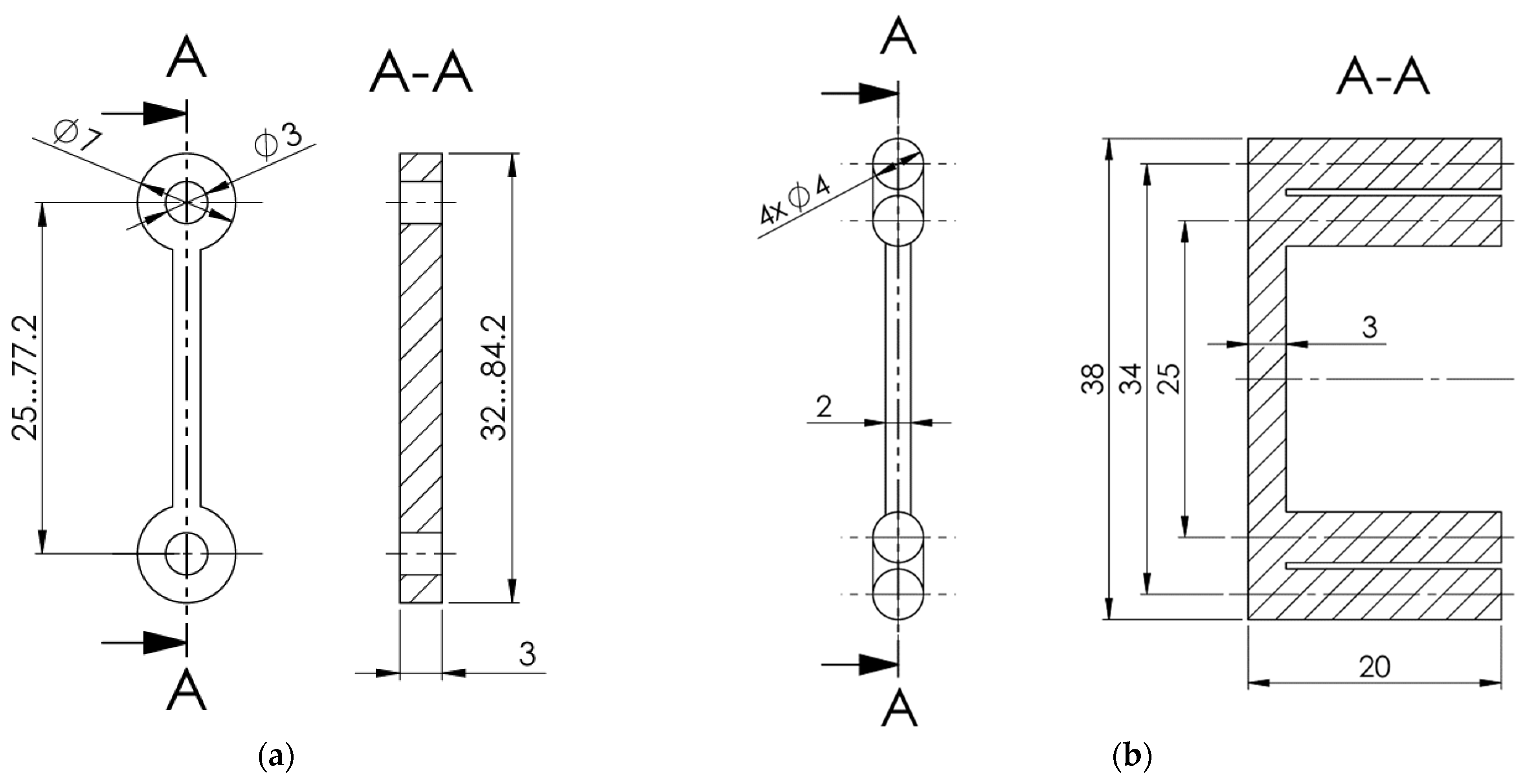
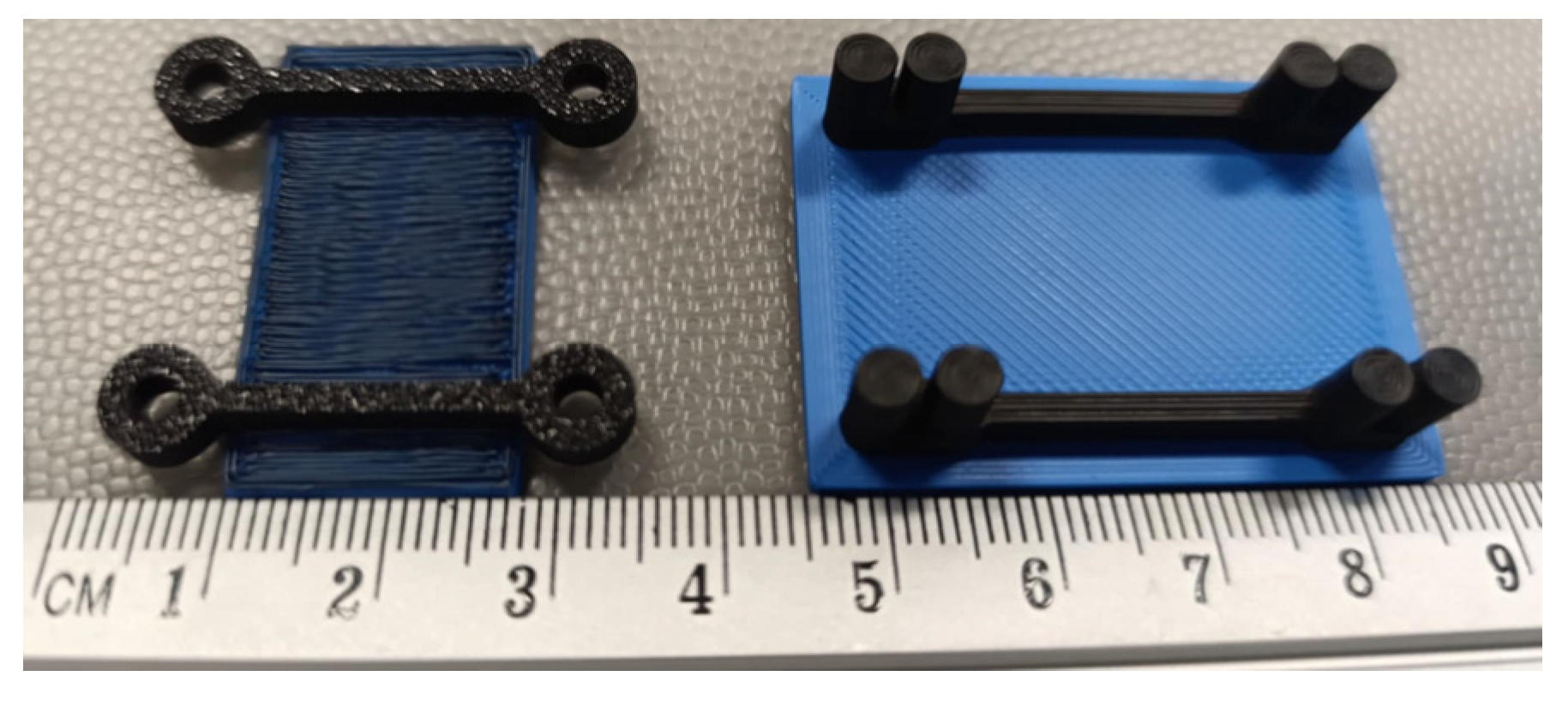
Figure 4 shows the 25 mm long conductive pathways fabricated with bolted and wrapped wire connections (without wires). All these specimens were modeled and manufactured using the Bambu Studio slicing software and a P1S printer, with the same materials and printing settings as those used for the specimens shown in
Figure 2. As in the previous specimens (
Figure 2), the elements, shown in
Figure 4, utilize the PLA (blue) plate as a fixing base to ensure the stability of geometry and measurement. To ensure fabrication quality, the specimens with bolted connections were produced in a bottom-up position, resulting in the base plate’s darkest color, as shown in
Figure 4.
2.3. Conductivity Assessment Methods
Electrical conductivity determines the efficiency criteria of CP in this study. Its measurement methods depend on the geometry of the 3D-printed structure and the necessary precision. Blachowicz et al. [
43] classified the following techniques as the most suitable for the FFF printed pathways:
The two-point probe method is extensively employed for determining electrical resistance due to its procedural simplicity and minimal instrumentation requirements. This technique introduces an electric current through two probe-specimen interfaces and conducts through the test material. According to Ohm’s law, the voltage drop measured across the probes comes from the combined effect of the material’s intrinsic (bulk) resistance and the interfacial contact resistances at the probe–material junctions. This method yields reliable and accurate resistance measurements only under specific conditions: (a) when the probe material contact regions are sufficiently confined, ideally approximating point contacts, thus promoting a linear and well-defined current–voltage (I–V) characteristic; or (b) when the contact resistances are negligibly small relative to the bulk resistance of the material, typically by several orders of magnitude, such that their influence on the total measured resistance can be considered insignificant.
The four-point probe method effectively mitigates the limitations inherent to the two-probe method, particularly those stemming from contact resistance at the probe–material interfaces. In this measurement configuration, a controlled current is introduced through the two outer electrodes, while the resulting voltage drop is sensed independently by the two inner electrodes. This spatial decoupling of current injection and voltage measurement eliminates the influence of contact resistance at the voltage-sensing electrodes, as these probes conduct an insignificantly small current. Consequently, the measured voltage only reflects the intrinsic electric potential of the test sample, allowing higher precision in determining the electrical resistance.
Kwok et al. [
20] tested both the two-point and four-point measurement methods, finding that the contact resistance was minimal (±2%) compared to the total resistance. Consequently, the two-point method was adopted for all subsequent electrical measurements. Zhang et al. [
38] and Flowers et al. [
39] utilized the two-point method exclusively to measure conductivity. Kwok et al. [
20] and Flowers et al. [
39] applied silver ink (Electron Microscopy Sciences, catalog number: 12630) to small areas (width: 1–2 mm; length: 3–4 mm) at the ends of the samples to diminish the contact resistance between the measuring probes and the conductive thermoplastic composite. This study employs the four-probe technique to evaluate the electrical resistance of the samples (
Figure 1a).
Surface roughness should also be considered when measuring the resistance of conductive polymers. Commercial electrodes are not designed for uneven or soft surfaces and may struggle to establish reliable contact with 3D-printed pathways [
44]. A typical solution to this issue involves applying a layer of silver paint to the surface, creating a more dependable contact point and ensuring proper electrical connectivity [
45]. This approach mitigates the impact of surface irregularities and enhances the accuracy of the testing results. Therefore, this study utilizes an eutectic indium–gallium (In-Ga) alloy paste to ensure a uniform current distribution across the entire cross-sectional area of each stripe-like sample. Due to its eutectic composition, the In-Ga paste remains liquid under ambient conditions, allowing it to closely conform to the surface morphology of the fabricated samples. Both terminal faces of each sample were coated with the In-Ga paste, ensuring complete coverage of the cross-section, as shown in
Figure 5. This configuration enables an almost homogeneous current density throughout the sample and establishes a stable, low contact resistance between the probe and the test material.
The voltage measured between the inner probes is then given as
where
ρ and
R denote the electric resistivity and resistance of the sample;
L is the distance between the inner voltage-sensing probes;
A(=
b·
h) represents the cross-section area of the conductive pathway; and
b and
h are the sample width and height. The resistivity of the conductive tracks was calculated using the following formula
where
σ and
l are the conductivity and length of the conductive track.
The electrical resistivity of the printed conductive pathways (
Figure 2) is measured using the two-point probe and four-point probe methods. The first method utilizes a universal VC505 multimeter (Orangjo, Shenzhen, China). The four-point probe measurement setup applies a 100 µA current at two outer contact points; the inner probes monitor the resulting voltage drop. A Keithley 2400 SourceMeter (Keithley Instruments, Solon, OH, USA) supplies the current, and voltage measurements are conducted using a Keithley 2002 multimeter (Keithley Instruments, Solon, OH, USA). To improve electrical connectivity and mitigate the uncertain effects of surface roughness in the printed samples, the electrode contact points were coated with an In-Ga paste, as shown in
Figure 5.
At the first measurement stage, the four-point probe measurements in
Figure 5 were conducted repeatedly, using distances of 10 mm, 15 mm, 20 mm, 25 mm, 30 mm, and 35 mm between the internal electrodes, with the electrodes placed at the top surface and side surface near the bottom contact with the base (blue) PLA. Thus, 36 measurements were achieved per conductive pathway. Hence, two groups of 36 measurements were created for the test samples shown in
Figure 2a,b. The first group compares the average resistivity obtained for different electrode distances (
Figure 5). The second group includes resistivity measurements of the top and bottom layers, specifically regarding the direction of the conductive pathway. Additionally, the third group consists of 18 measurements of the resistivity of the specimens fabricated with a 0.08 mm layer thickness (
Figure 2c), varying the distances between the electrodes. This group is an alternative to the first group, estimating the effect of building layer thickness on the pathway’s resistivity.
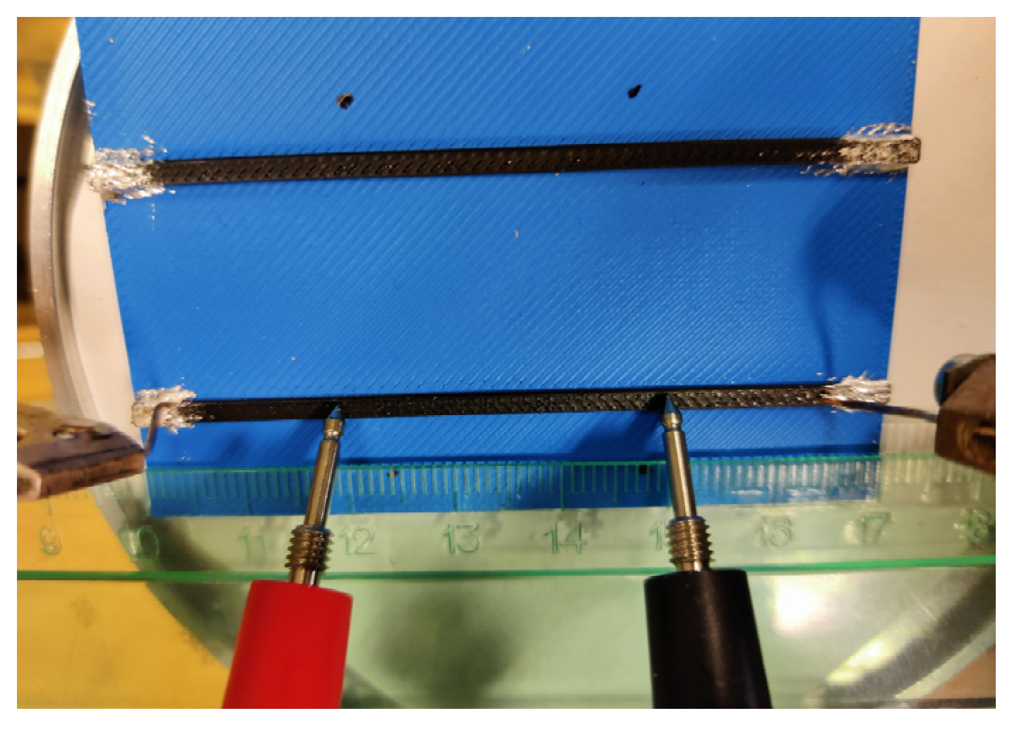
The second measurement stage employs the active circuit shown in
Figure 6 to evaluate the electrical performance of the printed conductive tracks. The circuit consists of a power source (Li-ion battery type 18650) “1”, a 3 mm red LED “4” with an operating current of 2 mA, and two conductive tracks (“3” and “5”) with bolted wire connections. These tests employ the four-probe technique, where a Keithley 2002 multimeter (Keithley Instruments, Solon, OH, USA) was used to measure voltage drops across various segments of the active circuit. Two different conductive lengths, i.e., 25 mm and 77.2 mm, were considered, and
Figure 6 shows the 25 mm long sample as an example.
Figure 6a shows the principal electrical scheme of the circuit. The battery voltage was measured between contact points “a” and “h” indicated in
Figure 6b; the voltage across each conductive pathway was recorded between points “d” and “e” (track “3”) and “f” and “g” (track “5”); the LED voltage drop was determined between points “e” and “f.” Following these measurements, the circuit was deactivated using the switch button “2”, and the Keithley 2002 multimeter was connected at points “b” and “c” to measure the total current of the circuit. The resistance values were calculated based on Ohm’s law. These values are presented in the “Total” column of
Table 4.
The circuit was then disassembled by removing the bolts, and each conductive track was evaluated independently using the four-probe method, as shown in
Figure 6c. The In-Ga paste was applied to the track ends to reduce interfacial resistance. A direct current (DC) of 100 µA was supplied using a Keithley 2400 SourceMeter through points “w” and “z” (
Figure 6c), and the DC voltage drops were measured between points “x” and “y” by the Keithley 2002 multimeter. These measurements were repeated three times per track to ensure the consistency of the results. The resulting voltage and current data were used to calculate the resistance of each conductive pathway. These values are presented in the “Track” column of
Table 4. Finally, the contact resistance at each bolted interface (points “d”, “e”, “f”, and “g” in
Figure 6b) was determined by subtracting the intrinsic track resistance (the “Track” column of
Table 4) from the “Total” resistance.
Table 4 summarizes the resultant values in the “Contact” column.
Table 4 also describes the resistivity of the printed pathway estimated by Equation (2) in the last column.
2.5. The Illustrative Prototypes
The Nano Long Range drone [
47] was selected for its compact size, lightweight design, and ease of use. It is a compact quadcopter designed for a 1–2 km flight range. The drone weighs approximately 95–97 g and features a 135 × 135 × 22 mm
3 frame. Powered by a single 18650 Li-ion battery type, rated at 3.6 V nominal voltage, it benefits from the high energy density and low weight typical of this cell type. The battery supports flight durations of 10–15 min, depending on throttle use and conditions. The drone utilizes four Flywoo 1202.5 11,500 kV brushless motors (Flywoo, Shenzhen, China), operating at 3.7 V with a current draw of approximately 1.15 A at 50% throttle and 4.9 A at 100% throttle. These motors are paired with Gemfan 3018 two-blade propellers (Gemfan, Ningbo, China), optimized for efficient thrust in lightweight builds. The reference [
47] also includes an STL file with the precise drone geometry, which helps avoid modeling errors.
This study develops two simplified drone prototypes utilizing a Li-ion battery type 18650. The geometry and dimensions of the drone’s frame remain consistent with the Nano Long Range drone [
47] for both models. Prototype 1 represents the drone model with a single active circuit, serving as the basis for the theoretical analysis of circuit capacity. Prototype 2 features a more practical arrangement of the conductive pathways, ensuring the functionality of four active components. Due to the limitations of the conductive polymer, the drone’s motors were replaced with LEDs to lower power demands.
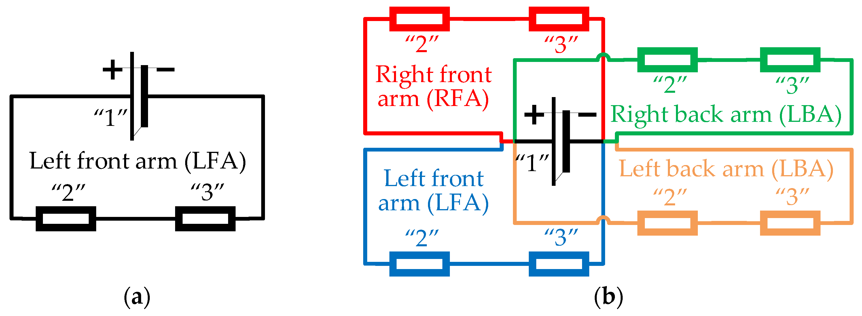
Figure 7 shows the principal electric schemes of these drone prototypes.
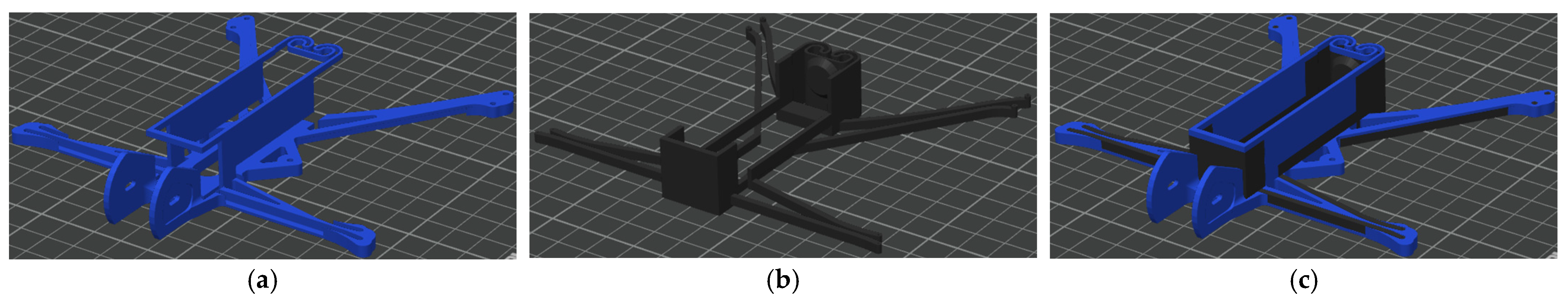
Figure 8 shows the 3D models of both drone prototypes created using SolidWorks software (Educational Edition 2023 SP2.1, Dassault Systèmes, Vélizy-Villacoublay, France).
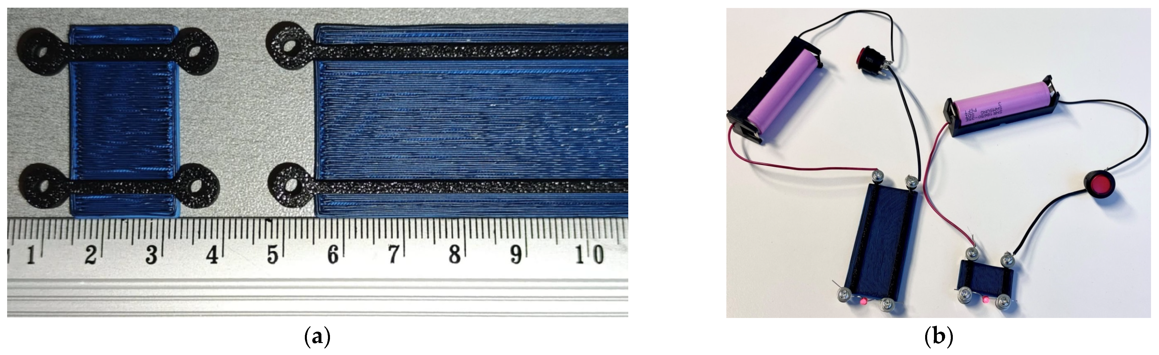
Figure 9 and
Figure 10 present the fabricated prototypes and the models prepared with the Bambu Studio software for 3D printing. Both drone prototypes incorporate a 2 × 3 mm
2 cross-section of the conductive pathways. In Prototype 1 (
Figure 9), the conductive paths were formed on the top of the front arm without compromising its structural integrity. On the contrary, Prototype 2 (
Figure 10) has conductive pathways integrated into the frame structure, preserving the drone’s external shape and accommodating the dimensional constraints of its arms, which are 4 mm in height and approximately 5 mm wide at their narrowest sections. This case exemplifies the additive manufacturing possibilities for forming integrated, conductive pathways that can entirely replace metal wires and contacts. In the latter model, the composite frame’s mechanical resistance has been outside the scope of this study, forming a topic for further research. A custom-designed battery holder was fabricated entirely from the conductive polymer, eliminating all metal components from the drone’s electrical system and demonstrating the feasibility of fully 3D-printed circuitry.
The drone prototypes were fabricated using the same conductive and non-conductive materials, slicing parameters, and dual-material printing methodology detailed in
Section 2.2, ensuring consistency in manufacturing conditions and conductivity performance. Thus, drone Prototype 1 (
Figure 8a) utilized 17.61 g of basic PLA (blue) and 7.28 g of conductive plastic (black), for a total weight of 24.89 g. Prototype 2 (
Figure 8b,c) has a total weight of 24.59 g, comprising 14.43 g of basic PLA and 10.16 g of conductive PLA materials. Dual-material printing involves additional filament consumption for purging during material changes to prevent cross-contamination between polymers. This extra material consumption, similar for both prototypes, is not reflected in the reported weights.


 ,
, 


