1. Introduction
A significant share of the application of fiber-reinforced polymer (FRP) in aerospace and automotive industries, and also in the marine, sport, ship, and medical sectors [
1,
2] results from their many advantages. The main advantage of FRPs is that the manufacturing technology using lamination techniques is rather easy and accessible. Moreover, FRPs are characterized by excellent unique mechanical properties, good chemical and dimensional stability, and also good corrosion and heat resistance [
3]. The most often used fiber-reinforced polymer composite laminates in the industry are carbon fiber (CFRP), glass fiber (GFRP), Kevlar fiber-reinforced polymer materials (KFRP), etc. For example, in the aviation industry, an A-320 aircraft has a 21.5% composite usage to its total weight, and a Boeing 787 and Airbus A350 have 50% of its total weight comprised of CFRP. These parts include the tail cone, center wing box, vertical and horizontal tails, etc. [
4]. GFRPs are mainly used indoors, but also in landing gears, fuselage body, tail spoiler, and body [
5] which also reduces the weight of the aircraft. Composite materials often require post-processing operations, such as turning [
6], drilling [
7], milling [
8,
9], or others to ensure dimensional requirements or to make holes for the assembly process. Machining of FRP composites is extremely difficult due to their inhomogeneous and anisotropic nature, therefore, it is the subject of many research works. Difficult-to-cut fiber reinforcements used in composite materials often are the main cause of an abrasive wear effect on the cutting tool used in machining [
10,
11].
Drilling is a commonly used method for creating accurate holes in various joints such as rivets, especially in the aviation industry. However, drilling causes damage, particularly delamination. Damages caused by drilling are widespread and significantly impact the load-bearing capacity and reliability of components, but also cause assembly tolerance errors [
12,
13]. In the aircraft industry alone, drilling-induced delamination is responsible for approximately 60% of part rejections during the final assembly. To prevent material failure, it’s essential to use appropriate tools and optimal drilling conditions [
14].
The most common types of damage, besides delamination, caused by the machining of GFRP composites are fiber pullouts, interlaminar delamination, fiber/matrix debonding, fuzzing, matrix melting, and softening [
15]. Delamination is caused by a combination of two mechanisms: mechanical and thermal damage, and it occurs when the tool exits the composite material due to feed forces. Delamination during machining can occur in two types: peel-up delamination and push-out delamination. Peel-up delamination occurs at the top surface of the composite materials when the upper layer fibers are not properly cut due to improper machining conditions and when the cutting edges of the tool touch the laminate. The peeling force generated by the slope of a drill flute removes the top layers, causing peel-up delamination [
16]. Push-out delamination occurs at the down surface of the machined composite, as the drilled composite is subjected to axial and bending forces [
17]. As it was found in previous research on FRP composites drilling the push-out delamination is more critical than the peel-up [
18,
19] and is related to technological parameters of drilling [
20,
21].
The quality of the drilled holes is strongly influenced by the possible damages that take place due to composite unique characteristics such as anisotropy, non-homogeneity, and abrasive and hard-reinforced fibers. The main quality attributes of the drilled holes are hole size, circularity, delamination, surface roughness, and heat-affected zone. These characteristics are investigated by several researchers to find the optimum combination of input factors to achieve good-quality holes in drilled FRPs.
The primary control factors that affect the surface quality of the holes drilled in laminated composite materials are the cutting speed, drill tool type, feed per tooth, laminate thickness, weight fraction, influence of the use of the drill support, specific areas of the hole and particular manufacturing features. There are some experimental design approaches to statistically investigate the influence of control factors on a target, e.g., factorial design and Taguchi method. Some researchers used this method to investigate the quality of the drilled holes in composite materials. Malik et al. [
22], using factorial design, investigated the drilling performance of GFRP composite, based on the thrust force, temperature, and delamination factor, and concluded that the best drilling performance was achieved by the solid carbide tool at a low feed rate. Taguchi method was used by Ngah et al. [
23] to investigate the influence of process parameters such as spindle speed, feed rate, type of drill bits, and geometry on the delamination of drilled holes in kenaf-glass fiber-reinforced unsaturated polyester composite. One of the conclusions was that the quality of the drill hole could be improved using a twist drill bit.
Some research has shown that the optical roughness measurements are less sensitive to measurement position than the stylus, and increase the accuracy of roughness measurement for machined FRP surfaces [
24]. Kim et al. [
25] using a CFRP workpiece consisting of 40 layers of IM7carbon fibers with an epoxy matrix in the quasi-isotropic layups, and a backup aluminum plate with predrilled holes 3 mm larger than the drill’s nominal size, investigate the hole quality in terms of hole size and surface roughness. Using a contact profilometer, its stylus could not reach the narrow area where the deepest fiber pullout happened at the plies, resulting in some limitations of the measurements.
There are two different aspects regarding the drilling scheme of thin composite plates, backup drilling and drilling without the backup. Backup drilling or supported drilling supposes the placement of a backup plate under the specimen, while in unsupported drilling or drilling without the backup, there is nothing under the specimen. Some researchers conducted research on the influence of the use of support during drilling as an important factor from the point of view of delamination. Gemi et al. [
26] in their research on the drilling of different GFRP composite pipes tested the influence of different feed rates and back support on the thrust force, which influences the delamination. They also compared results with unsupported samples. It was found that the use of back support significantly increases the thrust force by 3 to 35%. Moreover, an increase in feed rate caused an increase in thrust force, and lower values of thrust force were obtained for cases without backup support. Tsao et al. [
27] examined how backup plates affect delamination when drilling composite materials with saw drills and core drills. Using the critical drilling thrust force it was calculated and compared with cases without backup at the onset of delamination. Based on the results both the saw drill and the core drill with backup generate a critical thrust force than those without backup. Compared to industrial experience, the results of this study show that the drill can be operated at a higher feed rate without damaging the delamination. Heidary et al. [
28] drilled composite samples with an HSS twist drill with and without support with different feed ranges (0.25 to 1.16 mm/r). It was found that the delamination factor of the supported specimens was decreased in the range of 1.8% to 20.7% compared to those drilled without backup support. Also in the research, [
29] the influence of the exit support plate (5 mm thick placed under the sample) and drilling parameters (feed rate, cutting speed, and drill point angle) on delamination in twist drilling of GFRPs was analyzed. It was found that delamination decreased in the range of 8–27% when using a backup plate under the composite specimen depending on the drilling parameters. The influence of support on multi-hole drilling for GFRP composite materials was examined in [
30]. The authors focused on thrust forces and exit delamination damage when two types of support were applied during drilling (round-hole array backing plate and square-hollow backing plate). For support in the form of a round-hole array backing plate, the value of thrust forces and exit delamination was constant and lower than for a square-hollow backing plate. Ciecielag in the research [
31] examined the influence of the GFRP and CFRP samples’ stiffness on the accuracy of drilled holes and delamination in the drilling process. The tests were performed with constant drilling parameters but the length of unsupported elements was various. The experiments found that the feed force increases with the increase in the length of the element for GFRP and CFRP samples. The length of unsupported elements also influences the accuracy of the drilled holes.
Knowledge of the mechanical properties of new composite materials that can be used, e.g., in aviation, is particularly important from the point of view of flight safety. Therefore, researchers conduct research on mechanical properties. Ya-Jung Lee et al. [
32,
33] applied in their tests polyester resin with glass-fiber-reinforced fillers for tests of mechanical properties (tensile strength, flexural strength, and Young’s modulus) for single and multiple fibers. They found that the vacuum infusion processed GFRP samples had better mechanical properties than the hand layup technique, which increased the porosity of those composites. Jesthi and Nayak [
34] based their research on improving the mechanical properties of marine application-based fiber-reinforced composite materials by hybridizing glass and carbon fibers. The research [
35] focuses on the influence of stacking sequence on the strength of hybrid composites composed of materials with varying stiffness and strength. It was found that hybrid composite laminates containing 50% carbon fiber reinforcement have the best flexural properties with carbon layers on the outside, while the alternating carbon/glass layup has the highest compressive strength. According to the findings, the stacking sequence has no effect on tensile strength.
From the survey in the literature, the following results were found:
There are few studies about drilling without a backup. The process of drilling without support is often used when drilling by robots of thin composite components that should be riveted, in the aerospace field.
There are many factors affecting the surface quality of the holes drilled in laminate composites, meaning delamination and surface roughness. The effect of drilling factors on the hole quality of fiber-reinforced polymer structures should be analyzed and understood for implementation in the industry.
There is a necessity to determine the mechanical characteristics of new composite materials which will be machined.
The main aim of this article is to investigate the quality of drilled holes, in very thin plates of glass fiber-reinforced polymers, drilled without a backup plate, the specimens being clamped from both sides during drilling operations, at different opening widths. The composite plates are manufactured by two different technologies, an innovative one called vacuum mold pressing and the well-known technology of autoclave vacuum bagging.
The novelty of the research presented in this study lies in a methodology that combines experimental design and statistical analysis to understand the effect of drilling parameters on the hole quality of fiber-reinforced polymer structures. Thus, the mechanical properties of a GFRP/epoxy composite, the delamination during drilling with different support widths, and the surface roughness of the drilled holes were investigated.
2. Materials and Methods
A methodology regarding the investigation of the quality of holes made in composite materials was proposed. The methodology consisted of several steps such as the design of experiments, manufacturing and machining of the samples, determination of the mechanical properties of the samples, measurement of delamination and surface roughness, and statistical analysis of the hole quality characteristics.
This study aimed to examine how specific technological drilling parameters, such as feed per tooth (
fz) and the width of the drilled sample affected the maximum cutting force, delamination, and surface roughness of the holes in various types of GFRP materials. The analyzed materials differ by wf ratio and technological manufacturing process. The goal was to obtain drilled holes of very high quality. The general experimental plan is presented in
Figure 1.
2.1. Materials and Manufacturing Process
The selection of the control factors depends on the particularities of the manufacturing technology, the material characteristics, and the specific zone of the hole. Optimization of the cutting speed was preliminarily made in a previous study [
36]. An optimal drill tool for laminated composite materials is a carbide drill, as is mentioned in [
22]. There were no studies about the influence of support width on the surface quality of the drilled hole found. Thus, support width, feed per tooth, weight fraction, and hole zone were chosen as the critical factors used for the surface quality analysis (delamination and surface roughness).
To carry out the research, GFRP plates were used and were drilled using different technological parameters. GFRP plates were used to more easily visualize the defects that appeared during the process of drilling and delamination of the layers. The GFRP plates after manufacturing were transparent so that any defect could be easily detected.
Several plates marked with A1 to A4 from GFRP were manufactured. A 2 × 2 Twill fabric of 280 g/sq from glass fibers was used as reinforcement material. An Epikote MGS LR135/LH 136 type epoxy matrix (Lange&Ritter GmbH, Gerlingen, Germany) was used for impregnation. For the plates marked with A1-A2-A3, 4 layers of twill fabric were used, and for the plates marked with A4, 8 layers were used. Stacking sequences were [0/90]4 and [0/90]8, respectively, for the boards marked with A4.
Wet impregnation technology was used for all types of plates. For the plates marked with A1–A3, an innovative composite plate manufacturing technology (
Figure 2a) was used (technology 1) and presented in detail in [
20,
36,
37]. The process involved the impregnation of the layers using the hand layup technology of the layers using a flat metal mold. At the end, the GFRP layers are covered with 3 µm-thick Mylar (Polyester film). In the stage where the resin is still unpolymerized (fluid) but after it has passed the gel time, the mold, together with impregnated GFRP and covered with foil, is passed through an installation like a calendar with two cylinders. In this way, the composite is pressed and the excess resin is pushed towards the edges of the composite. Once the resin is removed from the composite, the air bubbles from the composite are also removed.
Thus, the resin on the edges seals the surface between the mold and the composite. Due to the viscosity of the resin, air no longer enters the composition of the composite, resulting in a pressed composite without air bubbles in the board structure. When pressing and removing the excess resin, the volume of the composite decreases. In this way, together with the reduction of the material volume and the sealing of the edges between the foil and the mold, a vacuum pressure is produced in the material that keeps the composite material free of air bubbles. Pressing the GFRP plates with different cylinder forces resulted in obtaining different wf intentionally, in order to evaluate the behavior of these materials in the drilling process without support. The curing process for plates produced by technology 1 consists of treatment at 22 °C for 24 h followed by a heat treatment at 80 °C for 8 h.
A different method of vacuum bag forming, and autoclave curing was used to manufacture the plates marked with A4 (technology 2). The procedure and the technological parameters used in the autoclave are presented in detail in [
38] and include the hand layup of the layers and autoclave curing procedure (
Figure 2b). The Maroso autoclave (Maroso SRL, Pianezze, Italy) curing procedure consists of some steps. The temperature was increased from 0 °C to 80 °C in 30 min, applying a pressure of 4 bars. Then, the temperature was increased from 80 °C to 120 °C in 20 min and the pressure was kept at 4 bars. In the third step of the cycle, the temperature was kept at 120 °C and the pressure at 4 bars for 2 h. At the end of the cycle, the pressure was reduced to 0 bars, and the temperature was decreased to 60 °C in 30 min. This procedure is used to manufacture aviation components from FRP and the results obtained in the evaluation of the materials or the behavior of the materials in different processing can be used for other composite materials. The properties of the manufactured materials are presented in
Table 1.
2.2. Drilling Methodology
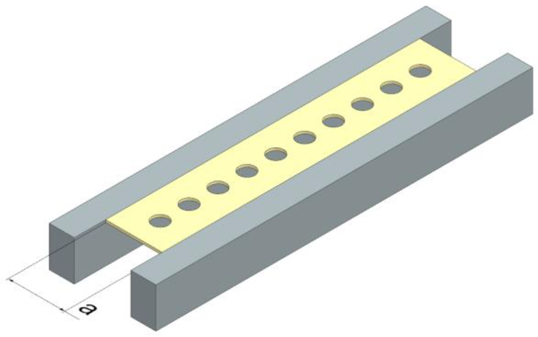
A Waterjet Combo (Legnica, Poland), which is an abrasive water jet cutter, was employed to cut GFRP plates into drilling samples. The samples differed in width (
Figure 3), were 250 mm long, and the thickness varied based on the composite type. The samples were clamped in a vice during processing. Each sample was drilled with a total of 10 holes, spaced 25 mm apart along the hole axis.
The drilling process was carried out using a vertical machining center, specifically the Avia VMC800HS (Avia, Warsaw, Poland), without the use of coolant. The drilling was conducted with a 2-edge carbide diamond-coated drill with a diameter of 12.726 mm, specifically the SD205A-12.726-56-14R1-C2 model (Seco, Erkrath, Germany). Throughout the experiments, holes were drilled in samples employing varying feeds per tooth (fz) of 0.04, 0.08, 0.12, and 0.16 mm/tooth and a constant cutting speed vc = 182 m/min. The selection of technological parameters was preceded by preliminary tests.
One of the measurements performed during the research was the measurement of cutting forces during the drilling process. The stand for measuring cutting forces in three axes Fx, Fy, Fz during drilling consisted of: a 9257B dynamometer from Kistler (Winterthur, Switzerland), a signal conditioning system, a DAQ module with an integrated A/D card, and dedicated DynoWare software V 5.0 (DynoJet, Germany) for recording curves. The research focused on the results of the maximum feed force Fz, which played a major role in the drilling process. For a high-quality hole and process improvement, it is important to monitor and control cutting forces during drilling.
2.3. Mechanical Properties Methodology
2.3.1. Tensile Strength Tests
To determine the tensile properties of various types of GFRP samples, the specimens underwent a static tensile test. In this research, for analyzing the mechanical behavior of the glass fiber composites, the specimens were tested using the servo-hydraulic testing machine Instron 8801 Dual Column (Instron, Norwood, MA, USA). Tensile tests were conducted following the ISO 527-5 standard, using type A samples. Samples with bonded tabs had the following dimensions: overall length—L1 = 250 mm, width—b = 25 mm, distance between the end tabs—L2 = 150 mm, and the thickness h varied based on the GFRP type. Five samples were performed for each of the GFRPs tested. The tests were performed at the environmental temperature of 23 ± 3 °C, and relative air humidity of 50 ± 5%. The specimens were loaded with a constant speed of 2 mm/min until breaking.
The tensile strength was calculated as:
where:
is the maximum tensile force, and
is the specimen cross-sectional area.
2.3.2. Bending Strength Tests
In order to determine the bending strength of various types of GFRP samples, three-point bending tests were conducted using a testing machine. Bending tests were conducted following the EN ISO 14125 standard, using type A samples. Samples had the following dimensions: overall length—
l = 60 mm, length of the span supports—
L = 40 mm, width—
b = 10 mm, and the thickness—
h, which varied based on the GFRP type. Five repetitions were performed for each variable. The tests were performed at an environmental temperature of 23 ± 3 °C and a relative air humidity of 50 ± 5%. The specimens were loaded with a constant speed of 5 mm/min until breaking. The bending strength was calculated as
where
is the axial load (force) at the fracture point,
is the length of the support span,
is the sample width, and
is the sample thickness.
2.4. Hole Quality Analysis Methodology
This study aimed to analyze the quality of the drilled holes, on the top and bottom surfaces. There are three main parameters that can characterize the quality of the holes, delamination, hole circularity and surface roughness. In this study, delamination analysis and surface roughness analysis was taken into consideration.
Two types of delamination were identified in this research. The first one, peel-up delamination occurs on the top surface and the second one, push-out delamination occurs on the down surface of the drilled sample when the drill exits the material. The delamination was quantified using the delamination factor F
d (
Figure 4). It is the ratio of the maximum diameter to the nominal diameter and is expressed by the following formula [
39]:
where
is the delamination factor,
is the maximum delaminated diameter drawn from the centerline of the hole, and
is the nominal diameter.
The diameters of peel-up and push-out delamination were measured using the software provided with the Keyence VHX-5000 (Osaka, Japan) optical microscope at 20× magnification. For each hole, a photo was taken on a microscope and the five maximum delamination diameters were measured on the upper and lower surfaces of the sample. The maximum delaminated diameter was drawn from the centerline of the hole’s nominal diameter to the point where the largest area of delamination was observed. The average value was determined from the five values and was considered during the analysis of the results.
Longitudinal cuts through the center of the holes were performed, in order to prepare the samples for roughness measurements, as is shown in
Figure 4a. It resulted in two halves, called A and B. Three surface roughness measurements were performed for each half of the hole of each specimen. Alicona Infinite Focus G5 (Raaba, Graz, Austria) optical surface roughness device, was used for the measurement of 3D surface roughness parameters. In these measurements, the sampling area was set as 2.25 × 1.50 mm
2, and a cutoff parameter of 0.8 mm. For the purposes of this article, the surface roughness Sa parameter was selected for analysis. Sa parameter expresses, as an absolute value, the difference in height of each point compared to the arithmetical mean of the surface. The average roughness Sa was calculated for each hole.
2.5. Design of the Experiments (DOE) and Statistical Analysis
Three experiments were designed choosing the control factors that affect the targets. The following targets were considered: delamination factor, maximum cutting force, and surface roughness of drilled holes in composite materials. Three general full factorial designs with 48-, 24-, and 32-factor combinations, were performed to be able to investigate the influence of the factors on targets for the three experiments.
In the first experiment, with the peel-up and push-out delaminations as targets, the support width, weight fraction of the composite material, and feed per tooth as control factors were considered for materials made by technology 1 (A1–A3), as is shown in
Table 2.
Maximum cutting force was taken as the target for the second experiment and the same control as the previous experiment was kept. In the third experiment, surface roughness (Sa) as a target, and support width, weight fraction, and hole zone as control factors were taken into consideration as is shown in
Table 3. The control factors used for the design of the experiments for material made by technology 2 (A4) are presented in
Table 4.
Statistical analysis allowed the investigation and characterization of the effects of control factors and their interactions on each target.
The contributions of the control factors to the maximum cutting force, Fd_peel-up, Fd_push-out, and Sa were determined using generalized linear models (GLM) analysis within the Minitab 19 software (Coventry, UK). The generalized linear model is a more general approach to performing an analysis of variance (ANOVA) [
40]. The significant factors were determined from the ANOVA table, for all the DOE. Thus, the F-values and the
p-values were analyzed in order to make a decision concerning the statistical significance. Also, the percentage contribution ratio (PC%) of each factor and interactions between factors were determined.
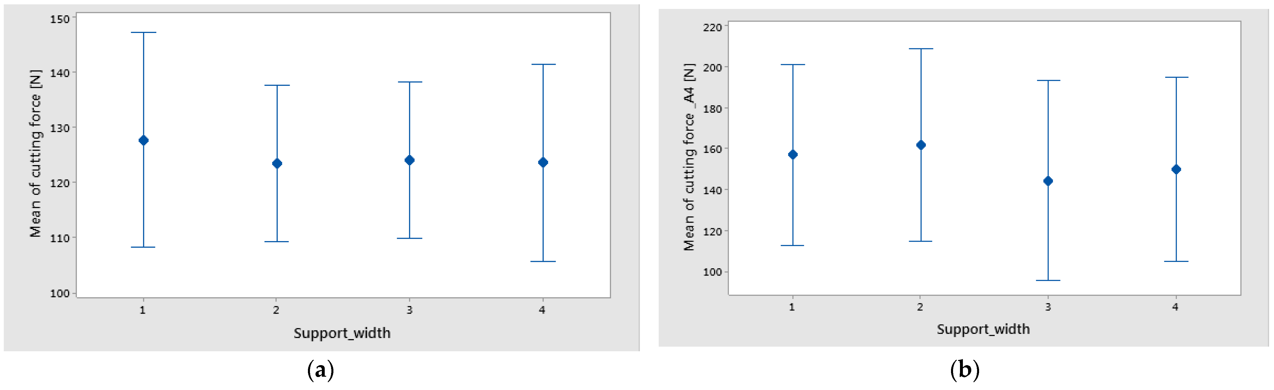
Graphical methods were used to evaluate the influence of control factors on target factors. Also to explain the statistical results, three types of graphs, the main effects plot, interaction effects plot, and interval plot of target versus control factors, were used.
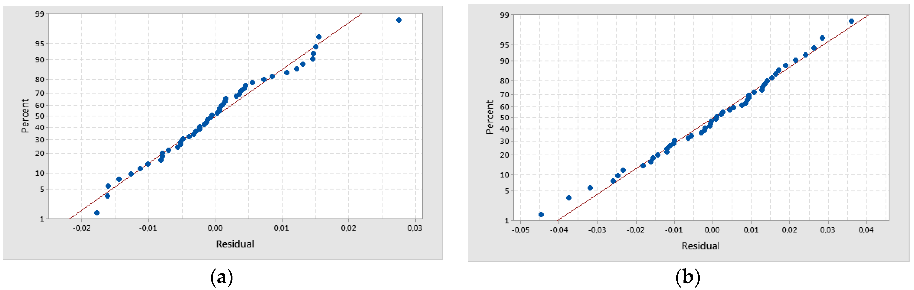
ANOVA assumptions were checked and validated as follows: residuals should be normally distributed, the variance of the observations in each treatment should be equal, and the response should be independent and identically distributed [
41].


